EP3982065A1 - Ice-making assembly and refrigerator comprising same - Google Patents
Ice-making assembly and refrigerator comprising same Download PDFInfo
- Publication number
- EP3982065A1 EP3982065A1 EP19931797.5A EP19931797A EP3982065A1 EP 3982065 A1 EP3982065 A1 EP 3982065A1 EP 19931797 A EP19931797 A EP 19931797A EP 3982065 A1 EP3982065 A1 EP 3982065A1
- Authority
- EP
- European Patent Office
- Prior art keywords
- water
- ice
- buffer portion
- making assembly
- water inlet
- Prior art date
- Legal status (The legal status is an assumption and is not a legal conclusion. Google has not performed a legal analysis and makes no representation as to the accuracy of the status listed.)
- Pending
Links
- XLYOFNOQVPJJNP-UHFFFAOYSA-N water Substances O XLYOFNOQVPJJNP-UHFFFAOYSA-N 0.000 claims abstract description 184
- 239000000872 buffer Substances 0.000 claims abstract description 60
- 238000013016 damping Methods 0.000 claims abstract description 50
- 238000002347 injection Methods 0.000 claims abstract description 38
- 239000007924 injection Substances 0.000 claims abstract description 38
- 238000007789 sealing Methods 0.000 claims description 6
- 230000008014 freezing Effects 0.000 abstract description 6
- 238000007710 freezing Methods 0.000 abstract description 6
- 238000010586 diagram Methods 0.000 description 7
- 230000003139 buffering effect Effects 0.000 description 4
- 238000000034 method Methods 0.000 description 4
- 230000000694 effects Effects 0.000 description 3
- 238000001746 injection moulding Methods 0.000 description 3
- 239000000243 solution Substances 0.000 description 3
- 238000005187 foaming Methods 0.000 description 2
- 238000009825 accumulation Methods 0.000 description 1
- 239000003651 drinking water Substances 0.000 description 1
- 230000007774 longterm Effects 0.000 description 1
- 239000000463 material Substances 0.000 description 1
- 238000005057 refrigeration Methods 0.000 description 1
Images




Classifications
-
- F—MECHANICAL ENGINEERING; LIGHTING; HEATING; WEAPONS; BLASTING
- F25—REFRIGERATION OR COOLING; COMBINED HEATING AND REFRIGERATION SYSTEMS; HEAT PUMP SYSTEMS; MANUFACTURE OR STORAGE OF ICE; LIQUEFACTION SOLIDIFICATION OF GASES
- F25C—PRODUCING, WORKING OR HANDLING ICE
- F25C1/00—Producing ice
-
- F—MECHANICAL ENGINEERING; LIGHTING; HEATING; WEAPONS; BLASTING
- F25—REFRIGERATION OR COOLING; COMBINED HEATING AND REFRIGERATION SYSTEMS; HEAT PUMP SYSTEMS; MANUFACTURE OR STORAGE OF ICE; LIQUEFACTION SOLIDIFICATION OF GASES
- F25C—PRODUCING, WORKING OR HANDLING ICE
- F25C1/00—Producing ice
- F25C1/22—Construction of moulds; Filling devices for moulds
- F25C1/25—Filling devices for moulds
-
- F—MECHANICAL ENGINEERING; LIGHTING; HEATING; WEAPONS; BLASTING
- F25—REFRIGERATION OR COOLING; COMBINED HEATING AND REFRIGERATION SYSTEMS; HEAT PUMP SYSTEMS; MANUFACTURE OR STORAGE OF ICE; LIQUEFACTION SOLIDIFICATION OF GASES
- F25D—REFRIGERATORS; COLD ROOMS; ICE-BOXES; COOLING OR FREEZING APPARATUS NOT OTHERWISE PROVIDED FOR
- F25D11/00—Self-contained movable devices, e.g. domestic refrigerators
-
- F—MECHANICAL ENGINEERING; LIGHTING; HEATING; WEAPONS; BLASTING
- F25—REFRIGERATION OR COOLING; COMBINED HEATING AND REFRIGERATION SYSTEMS; HEAT PUMP SYSTEMS; MANUFACTURE OR STORAGE OF ICE; LIQUEFACTION SOLIDIFICATION OF GASES
- F25D—REFRIGERATORS; COLD ROOMS; ICE-BOXES; COOLING OR FREEZING APPARATUS NOT OTHERWISE PROVIDED FOR
- F25D23/00—General constructional features
- F25D23/12—Arrangements of compartments additional to cooling compartments; Combinations of refrigerators with other equipment, e.g. stove
-
- F—MECHANICAL ENGINEERING; LIGHTING; HEATING; WEAPONS; BLASTING
- F25—REFRIGERATION OR COOLING; COMBINED HEATING AND REFRIGERATION SYSTEMS; HEAT PUMP SYSTEMS; MANUFACTURE OR STORAGE OF ICE; LIQUEFACTION SOLIDIFICATION OF GASES
- F25B—REFRIGERATION MACHINES, PLANTS OR SYSTEMS; COMBINED HEATING AND REFRIGERATION SYSTEMS; HEAT PUMP SYSTEMS
- F25B2500/00—Problems to be solved
- F25B2500/06—Damage
-
- F—MECHANICAL ENGINEERING; LIGHTING; HEATING; WEAPONS; BLASTING
- F25—REFRIGERATION OR COOLING; COMBINED HEATING AND REFRIGERATION SYSTEMS; HEAT PUMP SYSTEMS; MANUFACTURE OR STORAGE OF ICE; LIQUEFACTION SOLIDIFICATION OF GASES
- F25C—PRODUCING, WORKING OR HANDLING ICE
- F25C2400/00—Auxiliary features or devices for producing, working or handling ice
- F25C2400/14—Water supply
Definitions
- the present invention relates to the field of refrigeration devices, and particularly to an ice-making assembly and a refrigerator with the same.
- refrigerators are increasingly intelligent, and conventional refrigerators have functions such as automatic water intake, ice-making and supply of directly-potable water.
- water needs to be introduced from an external water source through a water pipe into a member such as an ice maker in the interior of the refrigerator.
- a water valve is opened, the pressure of water in the water pipe increases suddenly due to a larger pressure of the external water source.
- water droplets will splash outward to a member such as the ice maker.
- there will be potential safety hazards such as freezing of water droplets and short circuit.
- the present invention provides an ice-making assembly and a refrigerator with the same.
- An ice-making assembly comprising an ice maker and a water injection pipe for injecting water into the ice maker, wherein the water injection pipe has at least one flow damping member protruding inward from an inner wall, and/or the water injection pipe has at least one buffer portion protruding outwards.
- a refrigerator wherein the refrigerator comprises the ice-making assembly according to above.
- the flow damping member and/or buffer portion being disposed on the water injection pipe, the flow damping member breaks up the water when the water is fed, thereby reducing the water flow speed and water pressure; and/or, the water first flows into the buffer portion, the water pressure is offset, so that water flowing into the ice maker is under a small pressure, and potential safety hazards such as the freezing of water droplets and short circuit caused by water splashing are avoided.
- the present invention provides an ice-making assembly 1 comprising an ice maker 11 and a water injection pipe 12 for injecting water into the ice maker 11.
- the ice maker 11 employs any one type of ice maker in the prior art, and will not be detailed any more.
- the water injection pipe 12 comprises a water inlet section 123 for communicating with a water source, and a diversion section 124 located above the ice maker 11; wherein, the water source may be an external water source or an internal water tank of the refrigerator 100;
- the water inlet section 123 and the diversion section 124 may be one pipeline formed integrally, or two pipelines arranged separately.
- the water inlet section 123 there is no clear boundary between the water inlet section 123 and the diversion section 124.
- the section of pipeline near the water source is referred to as the water inlet section 123
- the section near the ice maker 11 is referred to as the diversion section 124
- a position where a total tendency of water flow changes is referred to as a connection of the water inlet section 123 and the diversion section 124.
- a direction in which the water inlet section 123 extends is a direction in which water flows in the water inlet section 123
- a direction in which the diversion section 124 extends is a direction in which water flows in the diversion section 124.
- the water injection pipe 12 further has at least one flow damping member 121 protruding inward from an inner wall.
- the flow damping member 121 breaks up partial water, and reduces the water flow speed and water pressure, so that water flowing into the ice maker 11 is under a small pressure, and potential safety hazards such as the freezing of water droplets and short circuit caused by water splashing are avoided.
- the flow damping member 121 is disposed on at least one of the water inlet section 123, the connection of the water inlet section 123 and the diversion section 124, and the diversion section 124.
- the flow damping member 121 is provided at the connection of the water inlet section 123 and the diversion section 124, and the flow damping member 121 is boss-shaped and breaks up water and meanwhile diverts the flow direction when the water is fed.
- At least two flow damping members 121 are provided at the connection of the water inlet section 123 and the diversion section 124, the at least two flow damping members 121 are wavy or zigzagged, or the at least two flow damping members 121 are disposed apart, and the flow damping members 121 are protrusions which extend away from the extension direction of the water inlet section 123, which means that the extension direction of the flow damping members 121 is substantially consistent with a direction away from the extension direction of the water inlet section 123.
- the flow damping members change the water flow direction while hindering the water flow and provide a better damping effect.
- the water injection pipe 12 has a first opening 126 and a first plug 127 for sealing the first opening 126.
- the flow damping members 121 are provided on the first plug 127.
- the water injection pipe 12 is manufactured by injection molding, and the first opening 126 is communicated with the interior and exterior of the water injection pipe 12 at the position where the flow damping members 121 are provided, so that the demolding process is smoother.
- the flow damping member 121 is provided at the water inlet section 123 and/or the diversion section 124.
- the flow damping member 121 is in a spiral shape, buffers the water flow while guiding the water flow, and avoids the impingement noise during the buffering process; alternatively, the flow damping member 121 is in the shape of an inclined plate, which can break up the water, weaken the kinetic energy of the water flow, and play a buffering role; alternatively, the flow damping member 121 is wedge-shaped and can better change the water flow direction; alternatively, the flow damping member 121 is arcuate, can make water flow impinge upon each other and better weaken the energy of the water flow.
- the flow damping member 121 protrudes toward the extension direction of the water inlet section 123 and/or the diversion section 124, and provides a better buffering effect.
- At least two flow damping members 121 are provided at the water inlet section 123 and/or the diversion section 124, and the at least two flow damping members 121 are distributed offset from each other, and can weaken the kinetic energy of the water flow and function to buffer.
- the water injection pipe 12 further has at least one buffer portion 122 protruding outwards.
- the buffer portion 122 protruding outwards.
- the buffer portion 122 is disposed on at least one of the connection of the diversion section 124 and the water inlet section 123 or the diversion section 124, so that the buffer effect is better.
- the buffer portion 122 is provided at the connection of the diversion section 124 and the water inlet section 123.
- the buffer portion 122 extends in a direction consistent with the extension direction of the water inlet section 123, which means that the buffer portion 122 extends in a direction substantially consistent with the extension direction of the water inlet section 123.
- an inner diameter of the buffer portion 122 is larger than an inner diameter of the water inlet section 123, so that when water flows from the water inlet section 123 into the buffer portion 122, the water pressure drops;
- the inner diameter of the buffer portion 122 may also not be larger than the inner diameter of the water inlet section 123, and it still can offset most of the water pressure, and the object of the present invention can also be achieved.
- the water injection pipe 12 further has a second opening 128 provided on the buffer portion 122 and a second plug 129 for sealing the second opening 128.
- the water injection pipe 12 is processed by injection molding, demolding is not easy to achieve when the inner diameter of the buffer portion 122 is larger than the inner diameter of the water inlet section 123, and the demolding process is made smoother through the second opening 128 and the second plug 129.
- the extension direction of the buffer portion 122 may also be set in a way that the buffer portion 122 extends in the extension direction of the water inlet section 123 as well as the extension direction of the diversion section 124; or in a way that the buffer portion 122 extends in the extension direction of the water inlet section 123 but extends away from the extension direction of the diversion section 124, so that after water flows into the buffer portion 122, most of the water pressure is offset, the water flow direction changes, and then water flows out of the buffer portion 122 into the diversion section 124.
- At least one said buffer portions 122 is provided at the diversion section 124, and the buffer portion 122 protrudes outward in the extension direction of the diversion section 124 so that after the water flows into the buffer portion 122, most of the water pressure is offset, and then water flows out into the diversion section 124.
- the inner wall of the buffer portion 122 is provided with at least one inwardly-protruding second flow damping member 1221 which can break up the water, weaken the kinetic energy of the water flow and function to buffer.
- second flow damping member 1221 which can break up the water, weaken the kinetic energy of the water flow and function to buffer.
- FIG. 11 and FIG. 12 Reference may be made to, but not limited to FIG. 11 and FIG. 12 for the structure of the second flow damping member 1221 and its connectional relationship with the buffer portion 122.
- connection of the buffer portion 122 and the diversion section 124 protrudes inwardly from the inner wall in a wedged shape, and can change the water flow direction to play a buffering role.
- the water injection pipe 12 has at least one said flow damping member 121 and at least one said buffer portion 122, and the buffer portion 122 is disposed apart from the flow damping member 121.
- the water injection pipe 12 further has a third opening 130 located on the buffer portion 122 and a third plug 131 for sealing the third opening 130.
- the water injection pipe 12 is processed by injection molding; the buffer portion 122 protrudes outward and makes it difficult to demold; therefore, the third opening 130 is communicated with the interior and exterior of the buffer portion 122 so that the demolding process is made smoother.
- the present invention further provides a refrigerator 100 including the ice-making assembly 1 as described above.
- the refrigerator 100 comprises an ice-making compartment 2
- the ice-making assembly 1 comprises a water pipe bracket 14 disposed adjacent to the ice-making compartment 2 to prevent a foaming material from entering the ice-making compartment 2 upon foaming.
- the water injection pipe 12 comprises a snap 125 capable of snap-fitting with the water pipe bracket 14 so that the water injection pipe 12 is firmly fixed.
- the water injection pipe 12 has at least one flow damping member 121 protruding inward from the inner wall, and the flow damping member 121 breaks up the water when water is fed; and/or, the water injection pipe 12 has at least one buffer portion 122 protruding outwards.
- the water injection pipe 12 When water is injected, the water first flows into the buffer portion 122, the water pressure is offset, so that water flowing into the ice maker 11 is under a small pressure, and potential safety hazards such as the freezing of water droplets and short circuit caused by water splashing are avoided.
Landscapes
- Engineering & Computer Science (AREA)
- Physics & Mathematics (AREA)
- Mechanical Engineering (AREA)
- Thermal Sciences (AREA)
- General Engineering & Computer Science (AREA)
- Chemical & Material Sciences (AREA)
- Combustion & Propulsion (AREA)
- Production, Working, Storing, Or Distribution Of Ice (AREA)
- Devices That Are Associated With Refrigeration Equipment (AREA)
Abstract
Description
- The present invention relates to the field of refrigeration devices, and particularly to an ice-making assembly and a refrigerator with the same.
- Currently, refrigerators are increasingly intelligent, and conventional refrigerators have functions such as automatic water intake, ice-making and supply of directly-potable water.
- To achieve the above functions, water needs to be introduced from an external water source through a water pipe into a member such as an ice maker in the interior of the refrigerator. At the moment when a water valve is opened, the pressure of water in the water pipe increases suddenly due to a larger pressure of the external water source. When the water is injected into the ice maker, water droplets will splash outward to a member such as the ice maker. After long-term accumulation of water droplets, there will be potential safety hazards such as freezing of water droplets and short circuit.
- Hence, it is necessary to provide an ice-making assembly and a refrigerator that prevent splashing phenomenon of water droplets when water is injected into the ice maker.
- To solve the above technical problems, the present invention provides an ice-making assembly and a refrigerator with the same.
- The present invention provides the following technical solutions to achieve the above object:
- An ice-making assembly, comprising an ice maker and a water injection pipe for injecting water into the ice maker, wherein the water injection pipe has at least one flow damping member protruding inward from an inner wall, and/or the water injection pipe has at least one buffer portion protruding outwards.
- A refrigerator, wherein the refrigerator comprises the ice-making assembly according to above.
- Advantageous effects of the present invention are as follows: with the flow damping member and/or buffer portion being disposed on the water injection pipe, the flow damping member breaks up the water when the water is fed, thereby reducing the water flow speed and water pressure; and/or, the water first flows into the buffer portion, the water pressure is offset, so that water flowing into the ice maker is under a small pressure, and potential safety hazards such as the freezing of water droplets and short circuit caused by water splashing are avoided.
- The following figures are used to provide further understanding of the present application and constitute a portion of the present application. Exemplary embodiments and their depictions of the present application are used to illustrate the present application and not intended for improper limitations of the present application. In the figures:
-
FIG. 1 is a structural schematic diagram of a refrigerator according to the present invention; -
FIG. 2 is a structural schematic diagram of an ice-making assembly inFIG. 1 ; -
FIG. 3 is a structural schematic diagram of a water injection pipe in a first embodiment of the present invention; -
FIG. 4 is a cross-sectional view taken along the line A-A' inFIG. 3 ; -
FIG. 5 is a structural schematic diagram of a water injection pipe in a second embodiment of the present invention; -
FIG. 6 is a cross-sectional view taken along the line B-B' inFIG. 5 ; -
FIG. 7 is a structural schematic diagram of a water injection pipe in a third embodiment of the present invention; -
FIG. 8 is a cross-sectional view taken along the line C-C' inFIG. 7 ; -
FIG. 9 is a structural schematic diagram of a water injection pipe in a fourth embodiment of the present invention; -
FIG. 10 is a cross-sectional view taken along the line D-D' inFIG. 9 ; -
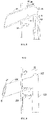
FIG. 11 is a structural schematic diagram of a water injection pipe in a fifth embodiment of the present invention; -
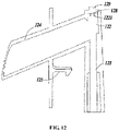
FIG. 12 is a cross-sectional view taken along the line E-E' inFIG. 11 . - 100--refrigerator, 1--ice-making assembly, 11--ice maker, 12--water injection pipe, 121--flow damping member, 122-buffer portion, 1221--second flow damping member, 123--water inlet section, 124--diversion section, 125--snap, 126--first opening, 127 --first plug, 128--second opening, 129--second plug, 130--third opening, 131--third plug, 14--water pipe bracket, 2--ice-making compartment.
- To make the objectives, technical solutions and advantages of the present application more apparent, technical solutions of the present application will be described clearly and completely in conjunction with specific embodiments and corresponding figures of the present application. All other embodiments obtained by those having ordinary skill in the art based on embodiments in the present application without making any inventive efforts fall within the extent of protection of the present application.
- As shown in
FIG. 1 through FIG. 12 , the present invention provides an ice-making assembly 1 comprising anice maker 11 and awater injection pipe 12 for injecting water into theice maker 11. - The
ice maker 11 employs any one type of ice maker in the prior art, and will not be detailed any more. - The
water injection pipe 12 comprises awater inlet section 123 for communicating with a water source, and adiversion section 124 located above theice maker 11; wherein, the water source may be an external water source or an internal water tank of therefrigerator 100; Thewater inlet section 123 and thediversion section 124 may be one pipeline formed integrally, or two pipelines arranged separately. - In the present application, there is no clear boundary between the
water inlet section 123 and thediversion section 124. For the convenience of description, the section of pipeline near the water source is referred to as thewater inlet section 123, the section near theice maker 11 is referred to as thediversion section 124, and a position where a total tendency of water flow changes is referred to as a connection of thewater inlet section 123 and thediversion section 124. - In addition, a direction in which the
water inlet section 123 extends is a direction in which water flows in thewater inlet section 123, and a direction in which thediversion section 124 extends is a direction in which water flows in thediversion section 124. - In a type of embodiment of the present invention, referring to
FIG. 1 through FIG. 8 , thewater injection pipe 12 further has at least oneflow damping member 121 protruding inward from an inner wall. When water is fed, theflow damping member 121 breaks up partial water, and reduces the water flow speed and water pressure, so that water flowing into theice maker 11 is under a small pressure, and potential safety hazards such as the freezing of water droplets and short circuit caused by water splashing are avoided. - The
flow damping member 121 is disposed on at least one of thewater inlet section 123, the connection of thewater inlet section 123 and thediversion section 124, and thediversion section 124. - Specifically, in a first embodiment, as shown in
FIG. 3 andFIG. 4 , theflow damping member 121 is provided at the connection of thewater inlet section 123 and thediversion section 124, and theflow damping member 121 is boss-shaped and breaks up water and meanwhile diverts the flow direction when the water is fed. - In a second embodiment, as shown in
FIG. 5 andFIG. 6 , at least twoflow damping members 121 are provided at the connection of thewater inlet section 123 and thediversion section 124, the at least twoflow damping members 121 are wavy or zigzagged, or the at least twoflow damping members 121 are disposed apart, and theflow damping members 121 are protrusions which extend away from the extension direction of thewater inlet section 123, which means that the extension direction of theflow damping members 121 is substantially consistent with a direction away from the extension direction of thewater inlet section 123. The flow damping members change the water flow direction while hindering the water flow and provide a better damping effect. - Furthermore, the
water injection pipe 12 has afirst opening 126 and afirst plug 127 for sealing thefirst opening 126. Theflow damping members 121 are provided on thefirst plug 127. During the processing, thewater injection pipe 12 is manufactured by injection molding, and thefirst opening 126 is communicated with the interior and exterior of thewater injection pipe 12 at the position where theflow damping members 121 are provided, so that the demolding process is smoother. - In a third embodiment, as shown in
FIG. 7 andFIG. 8 , theflow damping member 121 is provided at thewater inlet section 123 and/or thediversion section 124. Preferably, theflow damping member 121 is in a spiral shape, buffers the water flow while guiding the water flow, and avoids the impingement noise during the buffering process; alternatively, theflow damping member 121 is in the shape of an inclined plate, which can break up the water, weaken the kinetic energy of the water flow, and play a buffering role; alternatively, theflow damping member 121 is wedge-shaped and can better change the water flow direction; alternatively, theflow damping member 121 is arcuate, can make water flow impinge upon each other and better weaken the energy of the water flow. - Further, the
flow damping member 121 protrudes toward the extension direction of thewater inlet section 123 and/or thediversion section 124, and provides a better buffering effect. - Alternatively, in other embodiments, at least two
flow damping members 121 are provided at thewater inlet section 123 and/or thediversion section 124, and the at least twoflow damping members 121 are distributed offset from each other, and can weaken the kinetic energy of the water flow and function to buffer. - In another type embodiment of the present invention, referring to
FIG. 7 through FIG. 12 , thewater injection pipe 12 further has at least onebuffer portion 122 protruding outwards. When water is injected, part of the water flows into thebuffer portion 122, so that most of the water pressure is offset. As such, water flowing into theice maker 11 is under a small pressure, and potential safety hazards such as the freezing of water droplets and short circuit caused by water splashing are avoided. - The
buffer portion 122 is disposed on at least one of the connection of thediversion section 124 and thewater inlet section 123 or thediversion section 124, so that the buffer effect is better. - Specifically, in a fourth embodiment, as shown in
FIG. 9 andFIG. 10 , thebuffer portion 122 is provided at the connection of thediversion section 124 and thewater inlet section 123. Thebuffer portion 122 extends in a direction consistent with the extension direction of thewater inlet section 123, which means that thebuffer portion 122 extends in a direction substantially consistent with the extension direction of thewater inlet section 123. As a result, after water flows into thebuffer portion 122, most of the water pressure is offset, the water flow direction changes, then water flows out of thebuffer portion 122 away from the extension direction of thewater inlet section 123 into thediversion section 124, and the water impinges upon the water in thewater inlet section 123, thereby further reducing the water pressure. - Furthermore, an inner diameter of the
buffer portion 122 is larger than an inner diameter of thewater inlet section 123, so that when water flows from thewater inlet section 123 into thebuffer portion 122, the water pressure drops; certainly, the inner diameter of thebuffer portion 122 may also not be larger than the inner diameter of thewater inlet section 123, and it still can offset most of the water pressure, and the object of the present invention can also be achieved. - Further, the
water injection pipe 12 further has asecond opening 128 provided on thebuffer portion 122 and asecond plug 129 for sealing thesecond opening 128. During the processing, thewater injection pipe 12 is processed by injection molding, demolding is not easy to achieve when the inner diameter of thebuffer portion 122 is larger than the inner diameter of thewater inlet section 123, and the demolding process is made smoother through thesecond opening 128 and thesecond plug 129. - Certainly, when the
buffer portion 122 is disposed at the connection of thediversion section 124 and thewater inlet section 123, the extension direction of thebuffer portion 122 may also be set in a way that thebuffer portion 122 extends in the extension direction of thewater inlet section 123 as well as the extension direction of thediversion section 124; or in a way that thebuffer portion 122 extends in the extension direction of thewater inlet section 123 but extends away from the extension direction of thediversion section 124, so that after water flows into thebuffer portion 122, most of the water pressure is offset, the water flow direction changes, and then water flows out of thebuffer portion 122 into thediversion section 124. - In a fifth embodiment, referring to
FIG. 7 andFIG. 8 , at least one saidbuffer portions 122 is provided at thediversion section 124, and thebuffer portion 122 protrudes outward in the extension direction of thediversion section 124 so that after the water flows into thebuffer portion 122, most of the water pressure is offset, and then water flows out into thediversion section 124. - In addition, based on any of the above-mentioned types of
buffer portions 122, the inner wall of thebuffer portion 122 is provided with at least one inwardly-protruding secondflow damping member 1221 which can break up the water, weaken the kinetic energy of the water flow and function to buffer. Reference may be made to, but not limited toFIG. 11 andFIG. 12 for the structure of the secondflow damping member 1221 and its connectional relationship with thebuffer portion 122. - In addition, based on any of the above-mentioned types of
buffer portions 122, the connection of thebuffer portion 122 and thediversion section 124 protrudes inwardly from the inner wall in a wedged shape, and can change the water flow direction to play a buffering role. Reference may be made to, but not limited toFIG. 10 andFIG. 12 for the specific structure of thebuffer portion 122. - In a further type of embodiment of the present invention, referring to
FIG. 7 andFIG. 8 , thewater injection pipe 12 has at least one saidflow damping member 121 and at least one saidbuffer portion 122, and thebuffer portion 122 is disposed apart from theflow damping member 121. - Specifically, the
water injection pipe 12 further has athird opening 130 located on thebuffer portion 122 and athird plug 131 for sealing thethird opening 130. During the processing, thewater injection pipe 12 is processed by injection molding; thebuffer portion 122 protrudes outward and makes it difficult to demold; therefore, thethird opening 130 is communicated with the interior and exterior of thebuffer portion 122 so that the demolding process is made smoother. - The present invention further provides a
refrigerator 100 including the ice-making assembly 1 as described above. As shown inFIG. 1 andFIG. 2 , therefrigerator 100 comprises an ice-makingcompartment 2, and the ice-making assembly 1 comprises awater pipe bracket 14 disposed adjacent to the ice-makingcompartment 2 to prevent a foaming material from entering the ice-makingcompartment 2 upon foaming. - The
water injection pipe 12 comprises asnap 125 capable of snap-fitting with thewater pipe bracket 14 so that thewater injection pipe 12 is firmly fixed. - To conclude, in the ice-making assembly 1 and the
refrigerator 100 having the same in the present invention, thewater injection pipe 12 has at least oneflow damping member 121 protruding inward from the inner wall, and theflow damping member 121 breaks up the water when water is fed; and/or, thewater injection pipe 12 has at least onebuffer portion 122 protruding outwards. When water is injected, the water first flows into thebuffer portion 122, the water pressure is offset, so that water flowing into theice maker 11 is under a small pressure, and potential safety hazards such as the freezing of water droplets and short circuit caused by water splashing are avoided.
Claims (15)
- An ice-making assembly , comprising an ice maker and a water injection pipe for injecting water into the ice maker , wherein the water injection pipe has at least one flow damping member protruding inward from an inner wall, and/or the water injection pipe has at least one buffer portion protruding outwards.
- The ice-making assembly according to claim 1, wherein the flow damping member is disposed at a connection of the water inlet section and the diversion section, and the flow damping member is boss-shaped.
- The ice-making assembly according to claim 1, wherein at least two said flow damping members are disposed at the connection of the water inlet section and the diversion section, the at least two said flow damping members are wavy or zigzagged, or the at least two said flow damping members are disposed apart, and the flow damping members are protrusions which extend away from an extension direction of the water inlet section.
- The ice-making assembly according to claim 3, wherein the water injection pipe has a first opening and a first plug for sealing the first opening at the connection of the water inlet section and the diversion section, and the flow damping member is provided on the first plug.
- The ice-making assembly according to claim 1, wherein the flow damping member is provided at the water inlet section and/or the diversion section, and the flow damping member is in a spiral shape or an inclined plate shape or an arcuate shape.
- The ice-making assembly according to claim 1, wherein at least two said flow damping members are provided at the water inlet section and/or the diversion section, and the at least two said flow damping members are distributed offset from each other.
- The ice-making assembly according to claim 1, wherein the water injection pipe comprises a water inlet section for communicating with a water source, and a diversion section located above the ice maker, the buffer portion is disposed at a connection of the diversion section and the water inlet section, the buffer portion extends in the extension direction of the water inlet section as well as the extension direction of the diversion section; or the buffer portion extends in the extension direction of the water inlet section but extends away from the extension direction of the diversion section, or the buffer portion extends in a direction consistent with the extension direction of the water inlet section.
- The ice-making assembly according to claim 7, wherein the buffer portion extends in a direction consistent with the extension direction of the water inlet section, and an inner diameter of the buffer portion is larger than an inner diameter of the water inlet section.
- The ice-making assembly according to claim 8, wherein the water injection pipe is further provided with a second opening disposed on the buffer portion and a second plug for sealing the second opening.
- The ice-making assembly according to claim 1, wherein the water injection pipe comprises a water inlet section for communicating with a water source, and a diversion section located above the ice maker, at least one said buffer portion is disposed at the diversion section, and the buffer portion extends in the extension direction of the diversion section and protrudes outward.
- The ice-making assembly according to claim 1, wherein the inner wall of the buffer portion is provided with at least one inwardly-protruding second flow damping member.
- The ice-making assembly according to claim 1, wherein the connection of the buffer portion and the diversion section protrudes inwardly from the inner wall in a wedged shape.
- The ice-making assembly according to claim 1, wherein the water injection pipe has at least one said flow damping member and at least one said buffer portion, and the buffer portion is disposed apart from the flow damping member.
- The ice-making assembly according to claim 13, wherein the water injection pipe has a third opening located at the buffer portion and a third plug for sealing the third opening.
- A refrigerator, wherein the refrigerator comprises the ice-making assembly according to claim 1.
Applications Claiming Priority (2)
| Application Number | Priority Date | Filing Date | Title |
|---|---|---|---|
| CN201910489456.1A CN112050510B (en) | 2019-06-06 | 2019-06-06 | Ice making assembly and refrigerator having the same |
| PCT/CN2019/111183 WO2020244115A1 (en) | 2019-06-06 | 2019-10-15 | Ice-making assembly and refrigerator comprising same |
Publications (2)
| Publication Number | Publication Date |
|---|---|
| EP3982065A1 true EP3982065A1 (en) | 2022-04-13 |
| EP3982065A4 EP3982065A4 (en) | 2022-08-17 |
Family
ID=73608905
Family Applications (1)
| Application Number | Title | Priority Date | Filing Date |
|---|---|---|---|
| EP19931797.5A Pending EP3982065A4 (en) | 2019-06-06 | 2019-10-15 | Ice-making assembly and refrigerator comprising same |
Country Status (4)
| Country | Link |
|---|---|
| EP (1) | EP3982065A4 (en) |
| CN (1) | CN112050510B (en) |
| AU (1) | AU2019449503B2 (en) |
| WO (1) | WO2020244115A1 (en) |
Family Cites Families (22)
| Publication number | Priority date | Publication date | Assignee | Title |
|---|---|---|---|---|
| US3632049A (en) * | 1969-12-16 | 1972-01-04 | Westinghouse Electric Corp | Water delivery arrangement for automatic ice maker |
| JP3213162B2 (en) * | 1994-05-13 | 2001-10-02 | ホシザキ電機株式会社 | Sprinkler structure of falling ice machine |
| US6470701B2 (en) * | 1999-04-02 | 2002-10-29 | Dekko Heating Technologies, Inc. | Ice maker and method of making ice |
| KR20010037544A (en) * | 1999-10-18 | 2001-05-15 | 구자홍 | Water supply device to ice maker for refrigerator |
| KR100816090B1 (en) * | 2002-05-14 | 2008-03-24 | 엘지전자 주식회사 | Ice Maker Water Supply Of Refrigerator |
| KR100441021B1 (en) * | 2002-07-19 | 2004-07-21 | 삼성전자주식회사 | Water supply pipe for ice cube maker of refrigerator |
| JP2010043771A (en) * | 2008-08-11 | 2010-02-25 | Hoshizaki Electric Co Ltd | Water spray pipe for falling type ice-making machine |
| CN201301996Y (en) * | 2008-11-13 | 2009-09-02 | 邹建仁 | Faucet |
| KR101713327B1 (en) * | 2010-07-14 | 2017-03-08 | 엘지전자 주식회사 | Refirgerator |
| US9267721B2 (en) * | 2010-08-05 | 2016-02-23 | General Electric Company | Water supply apparatus in refrigerator |
| CN102261799A (en) * | 2011-06-20 | 2011-11-30 | 合肥美的荣事达电冰箱有限公司 | Refrigerator |
| CN202393120U (en) * | 2011-11-22 | 2012-08-22 | 合肥美的荣事达电冰箱有限公司 | Ice machine and refrigerator |
| CN103162502B (en) * | 2011-12-16 | 2017-02-15 | 博西华电器(江苏)有限公司 | Refrigeration device |
| DE102012222861A1 (en) * | 2012-12-12 | 2014-06-12 | BSH Bosch und Siemens Hausgeräte GmbH | Refrigeration unit with an icemaker |
| US20150377538A1 (en) * | 2014-06-30 | 2015-12-31 | Manitowoc Foodservice Companies, Llc | Water distribution system for ice-making machine |
| EP3469272A1 (en) * | 2016-06-08 | 2019-04-17 | Arçelik Anonim Sirketi | Ice maker for use in a refrigerator |
| US10309432B2 (en) * | 2016-06-22 | 2019-06-04 | Fmc Technologies, Inc. | Flow conditioner |
| KR102519052B1 (en) * | 2016-07-19 | 2023-04-07 | 삼성전자주식회사 | Valve assembly and refrigerator having the same |
| CN206687604U (en) * | 2016-11-03 | 2017-12-01 | 广东新宝电器股份有限公司 | Water pump valve with damping and silencing functions |
| MY195914A (en) * | 2017-03-08 | 2023-02-27 | Sharp Kk | Ice-Making System |
| CN207112192U (en) * | 2017-08-26 | 2018-03-16 | 刘茂松 | A kind of ceramic wear-resisting bend |
| CN107830668B (en) * | 2017-10-31 | 2019-08-27 | 海信容声(广东)冰箱有限公司 | A water inlet component of a refrigerator ice maker and a refrigerator |
-
2019
- 2019-06-06 CN CN201910489456.1A patent/CN112050510B/en active Active
- 2019-10-15 EP EP19931797.5A patent/EP3982065A4/en active Pending
- 2019-10-15 AU AU2019449503A patent/AU2019449503B2/en active Active
- 2019-10-15 WO PCT/CN2019/111183 patent/WO2020244115A1/en not_active Ceased
Also Published As
| Publication number | Publication date |
|---|---|
| WO2020244115A1 (en) | 2020-12-10 |
| EP3982065A4 (en) | 2022-08-17 |
| AU2019449503B2 (en) | 2022-12-22 |
| AU2019449503A1 (en) | 2022-01-20 |
| CN112050510B (en) | 2022-03-25 |
| CN112050510A (en) | 2020-12-08 |
Similar Documents
| Publication | Publication Date | Title |
|---|---|---|
| EP3252405B1 (en) | Water valve preventing redundant water from dripping and refrigerator using the same | |
| CN113340040B (en) | a drainage unit | |
| AU2019449503B2 (en) | Ice-making assembly and refrigerator comprising same | |
| CN2715072Y (en) | A water-freeing arrangement for refrigerator | |
| CN212157820U (en) | Low-temperature storage device | |
| WO2018032535A1 (en) | Refrigerator and water inlet pipe mounting structure for refrigerator ice maker thereof | |
| CN108088156A (en) | Defrost drain assembly and with its refrigerator | |
| CN212132965U (en) | Distributor with built-in jet orifice plate | |
| CN112050509A (en) | Ice making assembly and refrigerator having the same | |
| WO2023082802A1 (en) | Drainage pipe assembly and refrigerator | |
| CN102494471A (en) | Water drain pipe component for refrigerator and refrigerator with same | |
| CN218899192U (en) | Cap assembly and liquid heating container | |
| CN206037563U (en) | Drainage device and refrigerator | |
| CN201837163U (en) | Freezer drainage pipe assembly and freezer | |
| CN204963318U (en) | Connecting pipe subassembly and refrigerator | |
| CN214039122U (en) | Refrigerating and freezing device | |
| KR100643123B1 (en) | Inlet nozzle for cryogenic liquefied gas gas-liquid separator | |
| CN219913558U (en) | Ice maker structure and refrigerator | |
| KR200393020Y1 (en) | Suction diffusing nozzle in phase separator of cryogenic liquefied gas | |
| CN108800700A (en) | Refrigerating appliance | |
| CN208205504U (en) | Single mao of general connecting tube of evaporator | |
| CN223373824U (en) | Mixing arrangement and intelligent closestool | |
| CN204027152U (en) | For drain assembly, inner container of icebox and the refrigerator of refrigerator | |
| CN220062261U (en) | Refrigerator and kitchen appliance | |
| CN215909507U (en) | Double-temperature cabinet freezer lining opening condensation-proof pipe mounting structure |
Legal Events
| Date | Code | Title | Description |
|---|---|---|---|
| STAA | Information on the status of an ep patent application or granted ep patent |
Free format text: STATUS: THE INTERNATIONAL PUBLICATION HAS BEEN MADE |
|
| PUAI | Public reference made under article 153(3) epc to a published international application that has entered the european phase |
Free format text: ORIGINAL CODE: 0009012 |
|
| STAA | Information on the status of an ep patent application or granted ep patent |
Free format text: STATUS: REQUEST FOR EXAMINATION WAS MADE |
|
| 17P | Request for examination filed |
Effective date: 20211230 |
|
| AK | Designated contracting states |
Kind code of ref document: A1 Designated state(s): AL AT BE BG CH CY CZ DE DK EE ES FI FR GB GR HR HU IE IS IT LI LT LU LV MC MK MT NL NO PL PT RO RS SE SI SK SM TR |
|
| A4 | Supplementary search report drawn up and despatched |
Effective date: 20220715 |
|
| RIC1 | Information provided on ipc code assigned before grant |
Ipc: F25C 1/22 20180101AFI20220711BHEP |
|
| DAV | Request for validation of the european patent (deleted) | ||
| DAX | Request for extension of the european patent (deleted) | ||
| STAA | Information on the status of an ep patent application or granted ep patent |
Free format text: STATUS: EXAMINATION IS IN PROGRESS |
|
| 17Q | First examination report despatched |
Effective date: 20241126 |