EP3982061A1 - A heat exchanger assembly - Google Patents
A heat exchanger assembly Download PDFInfo
- Publication number
- EP3982061A1 EP3982061A1 EP20461565.2A EP20461565A EP3982061A1 EP 3982061 A1 EP3982061 A1 EP 3982061A1 EP 20461565 A EP20461565 A EP 20461565A EP 3982061 A1 EP3982061 A1 EP 3982061A1
- Authority
- EP
- European Patent Office
- Prior art keywords
- housing
- receiver drier
- heat exchanger
- exchanger assembly
- receiver
- Prior art date
- Legal status (The legal status is an assumption and is not a legal conclusion. Google has not performed a legal analysis and makes no representation as to the accuracy of the status listed.)
- Withdrawn
Links
Images




Classifications
-
- F—MECHANICAL ENGINEERING; LIGHTING; HEATING; WEAPONS; BLASTING
- F25—REFRIGERATION OR COOLING; COMBINED HEATING AND REFRIGERATION SYSTEMS; HEAT PUMP SYSTEMS; MANUFACTURE OR STORAGE OF ICE; LIQUEFACTION SOLIDIFICATION OF GASES
- F25B—REFRIGERATION MACHINES, PLANTS OR SYSTEMS; COMBINED HEATING AND REFRIGERATION SYSTEMS; HEAT PUMP SYSTEMS
- F25B39/00—Evaporators; Condensers
-
- F—MECHANICAL ENGINEERING; LIGHTING; HEATING; WEAPONS; BLASTING
- F25—REFRIGERATION OR COOLING; COMBINED HEATING AND REFRIGERATION SYSTEMS; HEAT PUMP SYSTEMS; MANUFACTURE OR STORAGE OF ICE; LIQUEFACTION SOLIDIFICATION OF GASES
- F25B—REFRIGERATION MACHINES, PLANTS OR SYSTEMS; COMBINED HEATING AND REFRIGERATION SYSTEMS; HEAT PUMP SYSTEMS
- F25B2339/00—Details of evaporators; Details of condensers
- F25B2339/04—Details of condensers
- F25B2339/044—Condensers with an integrated receiver
- F25B2339/0441—Condensers with an integrated receiver containing a drier or a filter
-
- F—MECHANICAL ENGINEERING; LIGHTING; HEATING; WEAPONS; BLASTING
- F25—REFRIGERATION OR COOLING; COMBINED HEATING AND REFRIGERATION SYSTEMS; HEAT PUMP SYSTEMS; MANUFACTURE OR STORAGE OF ICE; LIQUEFACTION SOLIDIFICATION OF GASES
- F25B—REFRIGERATION MACHINES, PLANTS OR SYSTEMS; COMBINED HEATING AND REFRIGERATION SYSTEMS; HEAT PUMP SYSTEMS
- F25B2339/00—Details of evaporators; Details of condensers
- F25B2339/04—Details of condensers
- F25B2339/047—Water-cooled condensers
-
- F—MECHANICAL ENGINEERING; LIGHTING; HEATING; WEAPONS; BLASTING
- F25—REFRIGERATION OR COOLING; COMBINED HEATING AND REFRIGERATION SYSTEMS; HEAT PUMP SYSTEMS; MANUFACTURE OR STORAGE OF ICE; LIQUEFACTION SOLIDIFICATION OF GASES
- F25B—REFRIGERATION MACHINES, PLANTS OR SYSTEMS; COMBINED HEATING AND REFRIGERATION SYSTEMS; HEAT PUMP SYSTEMS
- F25B2400/00—Component parts or details not otherwise provided for in this subclass
- F25B2400/16—Receivers
-
- F—MECHANICAL ENGINEERING; LIGHTING; HEATING; WEAPONS; BLASTING
- F28—HEAT EXCHANGE IN GENERAL
- F28D—HEAT-EXCHANGE APPARATUS, NOT PROVIDED FOR IN ANOTHER SUBCLASS, IN WHICH THE HEAT-EXCHANGE MEDIA DO NOT COME INTO DIRECT CONTACT
- F28D21/00—Heat-exchange apparatus not covered by any of the groups F28D1/00 - F28D20/00
- F28D2021/0019—Other heat exchangers for particular applications; Heat exchange systems not otherwise provided for
- F28D2021/008—Other heat exchangers for particular applications; Heat exchange systems not otherwise provided for for vehicles
- F28D2021/0084—Condensers
Definitions
- the present invention relates to a heat exchanger assembly, particularly a receiver drier - housing assembly, wherein a receiver drier is received in a housing connected to a heat exchanger.
- Conventional air conditioning system for example, air conditioning system for a vehicle includes a condenser, an evaporator, an expansion device, a compressor and a heater.
- the conventional air conditioning system configured with an expansion valve is also configured with a receiver drier that is disposed in a high-pressure section of the air conditioning system/ air conditioning loop.
- the receiver drier is usually located between a condenser and the expansion valve in the air conditioning loop.
- the receiver drier traps moisture and debris carried with condensed refrigerant received from the condenser. Accordingly, moisture and debris that is detrimental to critical components such as compressor disposed in the air-conditioning loop is prevented from reaching the compressor.
- the receiver drier is disposed near the condenser, particularly, the receiver drier is received in a receiver drier housing that is mounted on the condenser.
- receiver driers are used corresponding to different configurations of the condenser.
- different sizes of receiver drier are used corresponding to different sizes of the condensers.
- a different receiver drier housing is used to receive different configuration, particularly, different size of the receiver drier.
- a wrong version of the receiver drier is prevented from being received in the housing.
- a heat exchanger assembly that obviates the problems faced by the conventional heat exchanger assembly.
- a heat exchanger assembly that includes a receiver drier and a housing for the receiver drier. More particularly, a heat exchanger assembly that not only ensures that a right version of receiver drier is received in a corresponding housing but also ensures that a wrong version of the receiver drier is prevented from being received in the housing. Further, there is a need for a heat exchanger assembly configured with redundant features to ensure only a right version of a receiver drier is received in the corresponding housing and a wrong version is prevented from being received in the housing.
- a heat exchanger assembly configured with a failsafe arrangement that involves more than one feature to ensure that only a right version of a receiver drier is received in the corresponding housing while the wrong version is prevented from being received in the housing. More specifically, even when one feature fails, another feature still ensures that only a right version of the receiver drier is received in the corresponding housing and wrong version is prevented from being received in the housing.
- An object of the present invention is to provide a heat exchanger assembly, wherein a receiver drier and corresponding housing of the heat exchanger assembly include complementary features to ensure that only a right version of receiver drier is received in the corresponding housing while a wrong version is prevented from being received in the housing.
- Another object of the present invention is to provide a heat exchanger assembly that is simple in construction and that is configured with redundant features to ensure that only a right version of a receiver drier is received in the corresponding housing while the wrong version is prevented from being received in the housing.
- some elements or parameters may be indexed, such as a first element and a second element.
- this indexation is only meant to differentiate and name elements which are similar but not identical. No idea of priority should be inferred from such indexation, as these terms may be switched without betraying the invention. Additionally, this indexation does not imply any order in mounting or use of the elements of the invention.
- a heat exchanger assembly includes a receiver drier and a housing for the receiver drier.
- the receiver drier includes a cut-out portion, while the housing includes a complementary protrusion portion protruding into the cut-out portion of the receiver drier.
- the cut-out portion is located at one of the ends of the receiver drier with an inlet and/or outlet of the receiver drier.
- the cut-out portion is located on a side of the receiver drier substantially in-between the ends of the receiver drier.
- the cut-out portion is a groove and the protrusion portion is a rib.
- a region of the receiver drier proximal to the groove is depressed radially inward to enable entry of the receiver drier into the housing such that the groove and the complementary rib are aligned with respect to each other, the groove and the complementary rib engage with each other when the receiver drier is rotated relative to the housing while being inside the housing.
- the groove protrudes substantially perpendicularly to the general axis of extension of the receiver drier into the housing.
- the receiver drier includes a protruding pin and the housing includes an aperture, wherein the protruding pin protrudes outside of the housing through the aperture.
- the housing includes at least two apertures, wherein the protruding pin protrudes outside of the housing through one of them.
- the housing includes a first half and a second half connected together to define an enclosure that encloses the receiver drier.
- the protrusion portion and the aperture are located at the first half of the housing.
- the protrusion portion is located at the first half of the housing, while the aperture is located at the second half of the housing.
- heat exchanger assembly includes a plate condenser also enclosed by the housing and connected to the receiver drier.
- the plate condenser is so arranged with respect to the receiver drier that their axes of general extension are parallel to each other.
- the present invention relates to a heat exchanger assembly that includes a receiver drier and a housing, wherein the receiver drier and the corresponding housing include complementary engaging elements formed thereon to interact with each other to ensure a right receiver drier variant is received in the corresponding housing and a wrong receiver drier variant is prevented from being received in the housing.
- the present invention can also be extended to a tubular element and a housing of an assembly, wherein the tubular element and the housing are configured with features that ensure a right tubular element variant is received in the corresponding housing and a wrong tubular element variant is prevented from being received in the housing.
- the tubular element and the housing include features to determine variant of tubular element received in the housing by mere visual inspection of an exterior of the housing without requiring dis-assembly of the housing.
- FIG. 1 illustrates an isometric view of a heat exchanger assembly 300, herein after referred to as assembly 300.
- the assembly 300 includes a receiver drier 100 and a housing 200.
- FIG. 2 illustrates a sectional view of the housing 200 depicting internal details thereof and an isometric view of the receiver drier 100.
- FIG. 3a illustrates a sectional view of the housing 200 with the receiver drier 100 received therein.
- FIG. 3b illustrates another sectional view depicting internal details of the housing including a rib 210A.
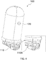
- FIG. 4 illustrates an isometric view of the receiver drier 100 of the assembly 300.
- FIG. 5 illustrates an isometric view of the housing of the assembly 300.
- the receiver drier 100 includes a cut-out portion 110 while the housing 200 includes a complementary protrusion portion 210 protruding into the cut-out portion 110 of the receiver drier 100.
- the cut-out portion 110 is located at one of the ends of the receiver drier 100 with an inlet and/or outlet of the receiver drier 100.
- the cut-out portion 110 may be located on a side of the receiver drier 100 substantially in-between the ends of the receiver drier 100.
- the cut-out portion 110 is a groove 110A and the protrusion portion 210 is the rib 210A. More specifically referring to FIG. 2 and FIG.
- the receiver drier 100 includes at least one groove 110A and at least one protruding pin 120 that are positioned based on the receiver drier variant.
- the corresponding housing 200 includes the complementary rib 210A, and optionally at least one aperture 220 formed thereon.
- the groove 110A formed on the receiver drier 100 receives the complementary rib 210A formed on the corresponding housing 200.
- the groove 110A protrudes substantially perpendicularly to the general axis of extension of the receiver drier 100 into the housing 200. Further, the protruding pin 120 formed on the receiver drier 100 is received in the aperture 220 formed on the corresponding housing 200.
- a region of the receiver drier 100 proximal to the groove 110A may be depressed radially inward to enable entry of the receiver drier 100 into the housing 200 such that the groove 110A and the complementary rib 210A are aligned with respect to each other.
- the groove 110A and the complementary rib 210A then engage with each other when the receiver drier 100 is rotated relative to the housing 200 while being inside the housing 200.
- the groove 110A on the receiver drier 100 is complementary to the rib 210A of the corresponding housing 200, for example, the groove 110A and the rib 210A are at same height "X" from base of the receiver drier 100 and the corresponding housing 200 respectively when measured parallel to the general axis of extension of the receiver drier 100.
- the receiver drier 100 may include the protruding pin 120 and the housing 200 may include the aperture 220 , wherein the protruding pin 120 protrudes outside of the housing 200 through the aperture 220.
- the housing 200 includes at least two apertures 220 , wherein the protruding pin 120 protrudes outside the housing 200 through one of them. This allows to indicate visibly which variant is present within the housing by protruding from a respective aperture 220.
- the protruding pin 120 on the receiver drier 100 is complementary to the aperture 220 of the corresponding housing 200.
- the protruding pin 120 and the aperture 220 are at same height "Y" from base of the receiver drier 100 and the corresponding housing 200 respectively when measured parallel to the general axis of extension of the receiver drier 100.
- the interaction between the protruding pin 120 on the receiver drier 100 and the aperture 220 of the corresponding housing 200 indicates the receiver drier variant received inside the housing as the protruding pin 120 protrudes out of the housing 200 through the aperture 220.
- the receiver drier is not receivable in housing of another version other than the corresponding housing as the rib 210A and the groove 110A configured on the receiver drier and housing do not match or the protruding pin and the aperture configured on the receiver drier and housing do not match.
- the groove 110A formed on the receiver drier capable of receiving the complementary rib 210A formed on the corresponding housing 200 and the protruding pin 120 of the receiver drier 100 engaging with the aperture 220 formed on the housing 200 , it is ensured that the right receiver drier variant is received in the corresponding housing and wrong version is prevented from being received in the housing.
- the complementary groove 110A and the rib 210A act as poke-yoke features that ensure that the right receiver drier variant is received in the corresponding housing and wrong version is prevented from being received in the housing.
- the housing 200 includes a first half 200A and a second half 200B connected together so that they form an enclosure to receive the receiver drier 100.
- both the protrusion portion 210, particularly, the rib 210A and the aperture 220 are located at the first half 200A of the housing 200 as illustrated in FIG. 6A.
- the protrusion portion 210, particularly, the rib 210A is located at the first half 200A of the housing 200, while the aperture 220 is located at the second half 200B of the housing 200.
- the heat exchanger assembly 300 includes a plate condenser 300A.
- the plate condenser 300A is also enclosed by the housing 200 and is connected to the receiver drier 100.
- the plate condenser 300A is arranged with respect to the receiver drier 100 so that their axes of general extension are parallel to each other.
Landscapes
- Engineering & Computer Science (AREA)
- Physics & Mathematics (AREA)
- Mechanical Engineering (AREA)
- Thermal Sciences (AREA)
- General Engineering & Computer Science (AREA)
- Detail Structures Of Washing Machines And Dryers (AREA)
Abstract
A heat exchanger assembly (300) includes a receiver drier (100) and a housing (200) for the receiver drier (100). The receiver drier (100) includes a cut-out portion (110), while the housing (200) includes a complementary protrusion portion (210) protruding into the cut-out portion (110) of the receiver drier (100).
Description
- The present invention relates to a heat exchanger assembly, particularly a receiver drier - housing assembly, wherein a receiver drier is received in a housing connected to a heat exchanger.
- Conventional air conditioning system, for example, air conditioning system for a vehicle includes a condenser, an evaporator, an expansion device, a compressor and a heater. Generally, the conventional air conditioning system configured with an expansion valve is also configured with a receiver drier that is disposed in a high-pressure section of the air conditioning system/ air conditioning loop. The receiver drier is usually located between a condenser and the expansion valve in the air conditioning loop. The receiver drier traps moisture and debris carried with condensed refrigerant received from the condenser. Accordingly, moisture and debris that is detrimental to critical components such as compressor disposed in the air-conditioning loop is prevented from reaching the compressor. The receiver drier is disposed near the condenser, particularly, the receiver drier is received in a receiver drier housing that is mounted on the condenser.
- However, different configurations of the condensers are used corresponding to different configurations of the air conditioning systems. Accordingly, different configurations / versions of receiver driers are used corresponding to different configurations of the condenser. For example, in a condenser assembly, different sizes of receiver drier are used corresponding to different sizes of the condensers. Generally, a different receiver drier housing is used to receive different configuration, particularly, different size of the receiver drier. However, it is to be ensured that only a particular configuration / variant of receiver drier, for example, a particular size of receiver drier corresponding to a particular condenser size/type is received in the corresponding housing mounted on the condenser during assembly of the air conditioning system. Also, it is to be ensured that a wrong version of the receiver drier is prevented from being received in the housing.
- In case a wrong version of receiver drier corresponding to a particular configuration of the condenser is received in the receiver drier housing, the performance parameters associated with the air conditioning system deviates from intended values, thereby detrimentally affecting the efficiency and the performance of the air conditioning system. Accordingly, it is to be ensured that only right version of the receiver drier corresponding to a particular configuration of the condenser is received in the receiver drier housing and wrong receiver drier is prevented from being received in the housing.
- Accordingly, there is a need for a heat exchanger assembly that obviates the problems faced by the conventional heat exchanger assembly. Particularly, there is a need for a heat exchanger assembly that includes a receiver drier and a housing for the receiver drier. More particularly, a heat exchanger assembly that not only ensures that a right version of receiver drier is received in a corresponding housing but also ensures that a wrong version of the receiver drier is prevented from being received in the housing. Further, there is a need for a heat exchanger assembly configured with redundant features to ensure only a right version of a receiver drier is received in the corresponding housing and a wrong version is prevented from being received in the housing. Particularly, there is a need for a heat exchanger assembly configured with a failsafe arrangement that involves more than one feature to ensure that only a right version of a receiver drier is received in the corresponding housing while the wrong version is prevented from being received in the housing. More specifically, even when one feature fails, another feature still ensures that only a right version of the receiver drier is received in the corresponding housing and wrong version is prevented from being received in the housing.
- An object of the present invention is to provide a heat exchanger assembly, wherein a receiver drier and corresponding housing of the heat exchanger assembly include complementary features to ensure that only a right version of receiver drier is received in the corresponding housing while a wrong version is prevented from being received in the housing.
- Another object of the present invention is to provide a heat exchanger assembly that is simple in construction and that is configured with redundant features to ensure that only a right version of a receiver drier is received in the corresponding housing while the wrong version is prevented from being received in the housing.
- In the present description, some elements or parameters may be indexed, such as a first element and a second element. In this case, unless stated otherwise, this indexation is only meant to differentiate and name elements which are similar but not identical. No idea of priority should be inferred from such indexation, as these terms may be switched without betraying the invention. Additionally, this indexation does not imply any order in mounting or use of the elements of the invention.
- A heat exchanger assembly includes a receiver drier and a housing for the receiver drier. The receiver drier includes a cut-out portion, while the housing includes a complementary protrusion portion protruding into the cut-out portion of the receiver drier.
- Generally, the cut-out portion is located at one of the ends of the receiver drier with an inlet and/or outlet of the receiver drier.
- In one option, the cut-out portion is located on a side of the receiver drier substantially in-between the ends of the receiver drier.
- Preferably, the cut-out portion is a groove and the protrusion portion is a rib.
- Generally, a region of the receiver drier proximal to the groove is depressed radially inward to enable entry of the receiver drier into the housing such that the groove and the complementary rib are aligned with respect to each other, the groove and the complementary rib engage with each other when the receiver drier is rotated relative to the housing while being inside the housing.
- Generally, the groove protrudes substantially perpendicularly to the general axis of extension of the receiver drier into the housing.
- Further, the receiver drier includes a protruding pin and the housing includes an aperture, wherein the protruding pin protrudes outside of the housing through the aperture.
- More specifically, the housing includes at least two apertures, wherein the protruding pin protrudes outside of the housing through one of them.
- In accordance with an embodiment of the present invention, the housing includes a first half and a second half connected together to define an enclosure that encloses the receiver drier.
- Generally, the protrusion portion and the aperture are located at the first half of the housing.
- Alternatively, the protrusion portion is located at the first half of the housing, while the aperture is located at the second half of the housing.
- Generally, heat exchanger assembly includes a plate condenser also enclosed by the housing and connected to the receiver drier.
- Specifically, in case of the heat exchanger assembly, the plate condenser is so arranged with respect to the receiver drier that their axes of general extension are parallel to each other.
- Other characteristics, details and advantages of the invention can be inferred from the description of the invention hereunder. A more complete appreciation of the invention and many of the attendant advantages thereof will be readily obtained as the same becomes better understood by reference to the following detailed description when considered in connection with the accompanying figures, wherein:
-
FIG.1 illustrates an isometric view of a heat exchanger assembly in accordance with an embodiment of the present invention; -
FIG. 2 illustrates a sectional view of a housing depicting internal details thereof and an isometric view of a receiver drier in accordance with an embodiment of the present invention; -
FIG. 3a illustrates a sectional view of the housing ofFIG. 2 with the receiver drier ofFIG. 2 received therein; -
FIG. 3b illustrates another sectional view depicting internal details of the housing including the rib; -
FIG. 4 illustrates an isometric view of the receiver drier of the heat exchanger assembly ofFIG. 1 ; -
FIG. 5 illustrates an isometric view of the housing of the heat exchanger assembly ofFIG. 1 ; - FIG. 6A illustrates a sectional view depicting interaction between complementary elements of the receiver drier and the housing of
FIG. 1 . - The present invention relates to a heat exchanger assembly that includes a receiver drier and a housing, wherein the receiver drier and the corresponding housing include complementary engaging elements formed thereon to interact with each other to ensure a right receiver drier variant is received in the corresponding housing and a wrong receiver drier variant is prevented from being received in the housing. However, the present invention can also be extended to a tubular element and a housing of an assembly, wherein the tubular element and the housing are configured with features that ensure a right tubular element variant is received in the corresponding housing and a wrong tubular element variant is prevented from being received in the housing. Also, the tubular element and the housing include features to determine variant of tubular element received in the housing by mere visual inspection of an exterior of the housing without requiring dis-assembly of the housing.
-
FIG. 1 illustrates an isometric view of aheat exchanger assembly 300, herein after referred to asassembly 300. Theassembly 300 includes areceiver drier 100 and ahousing 200.FIG. 2 illustrates a sectional view of thehousing 200 depicting internal details thereof and an isometric view of thereceiver drier 100.FIG. 3a illustrates a sectional view of thehousing 200 with thereceiver drier 100 received therein.FIG. 3b illustrates another sectional view depicting internal details of the housing including arib 210A.FIG. 4 illustrates an isometric view of thereceiver drier 100 of theassembly 300.FIG. 5 illustrates an isometric view of the housing of theassembly 300. - The receiver drier 100 includes a cut-out
portion 110 while thehousing 200 includes acomplementary protrusion portion 210 protruding into the cut-outportion 110 of the receiver drier 100. Generally, the cut-outportion 110 is located at one of the ends of the receiver drier 100 with an inlet and/or outlet of the receiver drier 100. Alternatively, the cut-outportion 110 may be located on a side of the receiver drier 100 substantially in-between the ends of the receiver drier 100. According to the embodiment, the cut-outportion 110 is agroove 110A and theprotrusion portion 210 is therib 210A. More specifically referring toFIG. 2 and FIG. 6A, the receiver drier 100 includes at least onegroove 110A and at least one protrudingpin 120 that are positioned based on the receiver drier variant. Thecorresponding housing 200 includes thecomplementary rib 210A, and optionally at least oneaperture 220 formed thereon. Thegroove 110A formed on the receiver drier 100 receives thecomplementary rib 210A formed on thecorresponding housing 200. Thegroove 110A protrudes substantially perpendicularly to the general axis of extension of the receiver drier 100 into thehousing 200. Further, the protrudingpin 120 formed on the receiver drier 100 is received in theaperture 220 formed on thecorresponding housing 200. A region of the receiver drier 100 proximal to thegroove 110A may be depressed radially inward to enable entry of the receiver drier 100 into thehousing 200 such that thegroove 110A and thecomplementary rib 210A are aligned with respect to each other. Thegroove 110A and thecomplementary rib 210A then engage with each other when the receiver drier 100 is rotated relative to thehousing 200 while being inside thehousing 200. As thegroove 110A on the receiver drier 100 is complementary to therib 210A of thecorresponding housing 200, for example, thegroove 110A and therib 210A are at same height "X" from base of the receiver drier 100 and thecorresponding housing 200 respectively when measured parallel to the general axis of extension of the receiver drier 100. The receiver drier 100 may include the protrudingpin 120 and thehousing 200 may include theaperture 220, wherein the protrudingpin 120 protrudes outside of thehousing 200 through theaperture 220. Thehousing 200 includes at least twoapertures 220, wherein the protrudingpin 120 protrudes outside thehousing 200 through one of them. This allows to indicate visibly which variant is present within the housing by protruding from arespective aperture 220. The protrudingpin 120 on the receiver drier 100 is complementary to theaperture 220 of thecorresponding housing 200. For example, the protrudingpin 120 and theaperture 220 are at same height "Y" from base of the receiver drier 100 and thecorresponding housing 200 respectively when measured parallel to the general axis of extension of the receiver drier 100. The interaction between the protrudingpin 120 on the receiver drier 100 and theaperture 220 of thecorresponding housing 200 indicates the receiver drier variant received inside the housing as the protrudingpin 120 protrudes out of thehousing 200 through theaperture 220. - The receiver drier is not receivable in housing of another version other than the corresponding housing as the
rib 210A and thegroove 110A configured on the receiver drier and housing do not match or the protruding pin and the aperture configured on the receiver drier and housing do not match. With thegroove 110A formed on the receiver drier capable of receiving thecomplementary rib 210A formed on thecorresponding housing 200 and the protrudingpin 120 of the receiver drier 100 engaging with theaperture 220 formed on thehousing 200, it is ensured that the right receiver drier variant is received in the corresponding housing and wrong version is prevented from being received in the housing. Thecomplementary groove 110A and therib 210A act as poke-yoke features that ensure that the right receiver drier variant is received in the corresponding housing and wrong version is prevented from being received in the housing. - The
housing 200 includes afirst half 200A and a second half 200B connected together so that they form an enclosure to receive the receiver drier 100. Generally, both theprotrusion portion 210, particularly, therib 210A and theaperture 220 are located at thefirst half 200A of thehousing 200 as illustrated in FIG. 6A. Alternatively, theprotrusion portion 210, particularly, therib 210A is located at thefirst half 200A of thehousing 200, while theaperture 220 is located at the second half 200B of thehousing 200. - The
heat exchanger assembly 300 includes aplate condenser 300A. Theplate condenser 300A is also enclosed by thehousing 200 and is connected to the receiver drier 100. Theplate condenser 300A is arranged with respect to the receiver drier 100 so that their axes of general extension are parallel to each other.
Claims (13)
- A heat exchanger assembly (300) comprising a receiver drier (100) and a housing (200) for the receiver drier (100), characterized in that the receiver drier (100) comprises a cut-out portion (110), while the housing (200) comprises a complementary protrusion portion (210) protruding into the cut-out portion (110) of the receiver drier (100).
- The heat exchanger assembly (300) according to claim 1, wherein the cut-out portion (110) is located at one of the ends of the receiver drier (100) with an inlet and/or outlet of the receiver drier (100).
- The heat exchanger assembly (300) according to claim 1, wherein the cut-out portion (110) is located on a side of the receiver drier (100) substantially in-between the ends of the receiver drier (100).
- The heat exchanger assembly (300) as claimed in the previous claim, wherein cut-out portion (110) is a groove (110A) and the protrusion portion (210) is a rib (210A).
- The heat exchanger assembly (300) as claimed in the previous claim, wherein region of the receiver drier (100) proximal to the groove (110A) is depressed radially inward to enable entry of the receiver drier (100) into the housing (200) such that the groove (110A) and the complementary rib (210A) are aligned to each other, the groove (110A) and the complementary rib (210A) engage with each other when the receiver drier (100) is rotated relative to the housing (200) while being inside the housing (200).
- The heat exchanger assembly (300) according to any of claims 2-5, wherein the groove (110A) protrudes substantially perpendicularly to the general axis of extension of the receiver drier (100) into the housing (200).
- The heat exchanger assembly (300) as claimed in any of the preceding claims, wherein the receiver drier (100) comprises a protruding pin (120), and the housing (200) comprises an aperture (220), wherein the protruding pin (120) protrudes outside of the housing (200) through the aperture (220).
- The heat exchanger assembly (300) according to claim 7, wherein the housing comprises at least two apertures (220), wherein the protruding pin (120) protrudes outside of the housing (200) through one of them.
- The heat exchanger assembly (300) according to any preceding claim, wherein the housing (200) comprises a first half (200A) and a second half (200B) connected together so that they enclose the receiver drier (100).
- The heat exchanger assembly (300) according to any of claims 8 and 9, wherein both the protrusion portion (210) and the aperture (220) are located at the first half (200A) of the housing (200).
- The heat exchanger assembly (300) according to any of claims 8 and 9, wherein the protrusion portion (210) is located at the first half (200A) of the housing (200), while the aperture (220) is located at the second half (200B) of the housing (200).
- The heat exchanger assembly (300) according to any preceding claim, wherein it comprises a plate condenser (300A) also enclosed by the housing (200) and connected to the receiver drier (100).
- The heat exchanger assembly according to claim 12, wherein the plate condenser (300A) is arranged with respect to the receiver drier (100) so that their axes of general extension are parallel to each other.
Priority Applications (1)
| Application Number | Priority Date | Filing Date | Title |
|---|---|---|---|
| EP20461565.2A EP3982061A1 (en) | 2020-10-06 | 2020-10-06 | A heat exchanger assembly |
Applications Claiming Priority (1)
| Application Number | Priority Date | Filing Date | Title |
|---|---|---|---|
| EP20461565.2A EP3982061A1 (en) | 2020-10-06 | 2020-10-06 | A heat exchanger assembly |
Publications (1)
| Publication Number | Publication Date |
|---|---|
| EP3982061A1 true EP3982061A1 (en) | 2022-04-13 |
Family
ID=72801446
Family Applications (1)
| Application Number | Title | Priority Date | Filing Date |
|---|---|---|---|
| EP20461565.2A Withdrawn EP3982061A1 (en) | 2020-10-06 | 2020-10-06 | A heat exchanger assembly |
Country Status (1)
| Country | Link |
|---|---|
| EP (1) | EP3982061A1 (en) |
Citations (3)
| Publication number | Priority date | Publication date | Assignee | Title |
|---|---|---|---|---|
| JPH09196513A (en) * | 1996-01-18 | 1997-07-31 | Zexel Corp | Receiver dryer monobloc type condenser |
| EP3517874A1 (en) * | 2018-01-29 | 2019-07-31 | Valeo Autosystemy SP. Z.O.O. | Heat exchanging module having a housing comprising an inner frame and an outer frame |
| EP3561427A1 (en) * | 2018-04-27 | 2019-10-30 | Valeo Autosystemy SP. Z.O.O. | Heat exchanger assembly |
-
2020
- 2020-10-06 EP EP20461565.2A patent/EP3982061A1/en not_active Withdrawn
Patent Citations (3)
| Publication number | Priority date | Publication date | Assignee | Title |
|---|---|---|---|---|
| JPH09196513A (en) * | 1996-01-18 | 1997-07-31 | Zexel Corp | Receiver dryer monobloc type condenser |
| EP3517874A1 (en) * | 2018-01-29 | 2019-07-31 | Valeo Autosystemy SP. Z.O.O. | Heat exchanging module having a housing comprising an inner frame and an outer frame |
| EP3561427A1 (en) * | 2018-04-27 | 2019-10-30 | Valeo Autosystemy SP. Z.O.O. | Heat exchanger assembly |
Similar Documents
| Publication | Publication Date | Title |
|---|---|---|
| US9410709B2 (en) | Multichannel condenser coil with refrigerant storage receiver | |
| KR101906812B1 (en) | Condenser integrated with receiver dryer | |
| CN105531554B (en) | Link block, heat exchanger and corresponding heat-exchanging component | |
| WO2013122450A1 (en) | An air-conditioning apparatus | |
| EP3982061A1 (en) | A heat exchanger assembly | |
| JPH112474A (en) | Cooling system | |
| CN110541802A (en) | Structure and method for preventing/reducing noise for refrigerator | |
| EP1329675A2 (en) | Refrigerating cycle of air-conditioner | |
| US6684661B1 (en) | Receiver dryer mounting bracket for a condenser system | |
| KR100421079B1 (en) | A condenserprovidedwithauxiliarypart with auxiliary parts and connectors for attaching auxiliary parts thereto | |
| US20200189349A1 (en) | Support device and air conditioning system for vehicle | |
| CN114761741A (en) | Temperature detection sensor fixing device and compressor | |
| JPWO2021019758A1 (en) | Outdoor unit of air conditioner and air conditioner | |
| EP3978837B1 (en) | A receiver drier housing | |
| JP2000074527A (en) | Recipient integrated refrigerant condenser | |
| CN213300278U (en) | Air conditioner and indoor unit thereof | |
| KR20150009865A (en) | Outdoor heat exchanger fixing structure and outdoor unit of air conditioner | |
| EP4194733A1 (en) | A connection system | |
| EP4296524B1 (en) | Compressor | |
| KR100531355B1 (en) | device for fixing fan motor of one body type air conditioner | |
| CN222123467U (en) | Air conditioner | |
| WO2018011911A1 (en) | Outdoor unit and air conditioner | |
| US20240391293A1 (en) | Air conditioner for vehicle | |
| KR20000000305U (en) | Compressor Assembly | |
| WO2013122451A1 (en) | Outdoor unit of an air-conditioning apparatus |
Legal Events
| Date | Code | Title | Description |
|---|---|---|---|
| PUAI | Public reference made under article 153(3) epc to a published international application that has entered the european phase |
Free format text: ORIGINAL CODE: 0009012 |
|
| STAA | Information on the status of an ep patent application or granted ep patent |
Free format text: STATUS: THE APPLICATION HAS BEEN PUBLISHED |
|
| AK | Designated contracting states |
Kind code of ref document: A1 Designated state(s): AL AT BE BG CH CY CZ DE DK EE ES FI FR GB GR HR HU IE IS IT LI LT LU LV MC MK MT NL NO PL PT RO RS SE SI SK SM TR |
|
| STAA | Information on the status of an ep patent application or granted ep patent |
Free format text: STATUS: THE APPLICATION IS DEEMED TO BE WITHDRAWN |
|
| 18D | Application deemed to be withdrawn |
Effective date: 20221014 |