EP3982003A1 - Air spring - Google Patents
Air spring Download PDFInfo
- Publication number
- EP3982003A1 EP3982003A1 EP20200875.1A EP20200875A EP3982003A1 EP 3982003 A1 EP3982003 A1 EP 3982003A1 EP 20200875 A EP20200875 A EP 20200875A EP 3982003 A1 EP3982003 A1 EP 3982003A1
- Authority
- EP
- European Patent Office
- Prior art keywords
- air spring
- bellows
- rolling bellows
- rolling
- wall reinforcement
- Prior art date
- Legal status (The legal status is an assumption and is not a legal conclusion. Google has not performed a legal analysis and makes no representation as to the accuracy of the status listed.)
- Granted
Links
Images


Classifications
-
- B—PERFORMING OPERATIONS; TRANSPORTING
- B60—VEHICLES IN GENERAL
- B60G—VEHICLE SUSPENSION ARRANGEMENTS
- B60G11/00—Resilient suspensions characterised by arrangement, location or kind of springs
- B60G11/26—Resilient suspensions characterised by arrangement, location or kind of springs having fluid springs only, e.g. hydropneumatic springs
- B60G11/27—Resilient suspensions characterised by arrangement, location or kind of springs having fluid springs only, e.g. hydropneumatic springs wherein the fluid is a gas
-
- F—MECHANICAL ENGINEERING; LIGHTING; HEATING; WEAPONS; BLASTING
- F16—ENGINEERING ELEMENTS AND UNITS; GENERAL MEASURES FOR PRODUCING AND MAINTAINING EFFECTIVE FUNCTIONING OF MACHINES OR INSTALLATIONS; THERMAL INSULATION IN GENERAL
- F16F—SPRINGS; SHOCK-ABSORBERS; MEANS FOR DAMPING VIBRATION
- F16F9/00—Springs, vibration-dampers, shock-absorbers, or similarly-constructed movement-dampers using a fluid or the equivalent as damping medium
- F16F9/02—Springs, vibration-dampers, shock-absorbers, or similarly-constructed movement-dampers using a fluid or the equivalent as damping medium using gas only or vacuum
- F16F9/04—Springs, vibration-dampers, shock-absorbers, or similarly-constructed movement-dampers using a fluid or the equivalent as damping medium using gas only or vacuum in a chamber with a flexible wall
- F16F9/0409—Springs, vibration-dampers, shock-absorbers, or similarly-constructed movement-dampers using a fluid or the equivalent as damping medium using gas only or vacuum in a chamber with a flexible wall characterised by the wall structure
-
- F—MECHANICAL ENGINEERING; LIGHTING; HEATING; WEAPONS; BLASTING
- F16—ENGINEERING ELEMENTS AND UNITS; GENERAL MEASURES FOR PRODUCING AND MAINTAINING EFFECTIVE FUNCTIONING OF MACHINES OR INSTALLATIONS; THERMAL INSULATION IN GENERAL
- F16F—SPRINGS; SHOCK-ABSORBERS; MEANS FOR DAMPING VIBRATION
- F16F9/00—Springs, vibration-dampers, shock-absorbers, or similarly-constructed movement-dampers using a fluid or the equivalent as damping medium
- F16F9/02—Springs, vibration-dampers, shock-absorbers, or similarly-constructed movement-dampers using a fluid or the equivalent as damping medium using gas only or vacuum
- F16F9/04—Springs, vibration-dampers, shock-absorbers, or similarly-constructed movement-dampers using a fluid or the equivalent as damping medium using gas only or vacuum in a chamber with a flexible wall
- F16F9/05—Springs, vibration-dampers, shock-absorbers, or similarly-constructed movement-dampers using a fluid or the equivalent as damping medium using gas only or vacuum in a chamber with a flexible wall the flexible wall being of the rolling diaphragm type
- F16F9/057—Springs, vibration-dampers, shock-absorbers, or similarly-constructed movement-dampers using a fluid or the equivalent as damping medium using gas only or vacuum in a chamber with a flexible wall the flexible wall being of the rolling diaphragm type characterised by the piston
-
- B—PERFORMING OPERATIONS; TRANSPORTING
- B60—VEHICLES IN GENERAL
- B60G—VEHICLE SUSPENSION ARRANGEMENTS
- B60G2202/00—Indexing codes relating to the type of spring, damper or actuator
- B60G2202/10—Type of spring
- B60G2202/15—Fluid spring
- B60G2202/152—Pneumatic spring
-
- B—PERFORMING OPERATIONS; TRANSPORTING
- B60—VEHICLES IN GENERAL
- B60G—VEHICLE SUSPENSION ARRANGEMENTS
- B60G2206/00—Indexing codes related to the manufacturing of suspensions: constructional features, the materials used, procedures or tools
- B60G2206/01—Constructional features of suspension elements, e.g. arms, dampers, springs
- B60G2206/40—Constructional features of dampers and/or springs
- B60G2206/42—Springs
- B60G2206/424—Plunger or top retainer construction for bellows or rolling lobe type air springs
-
- B—PERFORMING OPERATIONS; TRANSPORTING
- B60—VEHICLES IN GENERAL
- B60G—VEHICLE SUSPENSION ARRANGEMENTS
- B60G2206/00—Indexing codes related to the manufacturing of suspensions: constructional features, the materials used, procedures or tools
- B60G2206/01—Constructional features of suspension elements, e.g. arms, dampers, springs
- B60G2206/70—Materials used in suspensions
- B60G2206/71—Light weight materials
- B60G2206/7101—Fiber-reinforced plastics [FRP]
-
- B—PERFORMING OPERATIONS; TRANSPORTING
- B60—VEHICLES IN GENERAL
- B60G—VEHICLE SUSPENSION ARRANGEMENTS
- B60G2206/00—Indexing codes related to the manufacturing of suspensions: constructional features, the materials used, procedures or tools
- B60G2206/01—Constructional features of suspension elements, e.g. arms, dampers, springs
- B60G2206/70—Materials used in suspensions
- B60G2206/73—Rubber; Elastomers
Definitions
- the invention relates to an air spring with an air spring rolling bellows made of elastomer material with reinforcing layers embedded within the rolling bellows wall, the air spring being clamped in between a sprung and an unsprung mass.
- the air spring cover is as a rule connected to the vehicle body, that is to say the sprung mass, whereas the air spring piston is fastened to the chassis, that is to say to the unsprung mass.
- the air springs are connected to an air supply, customarily by means of hoses and/or air lines which, via corresponding connections and valves for air delivery and control on the air spring cover, are connected to the working space or pressure space within the air spring bellows.
- the air is supplied by way of a pressure accumulator located in the vehicle, which is filled by means of a compressor and then provides the supply of air for the individual sprung systems by way of a controller.
- the air-spring controller is often incorporated in the rest of the vehicle control system.
- connection parts and the air spring bellows thus enclose the working space which is under internal pressure and contains the air spring volume and which is connected to the air connection which is often provided in the cover.
- US 6,386,524 B1 discloses an air spring in which the customarily present construction of the connection between the air spring bellows and the connection parts becomes clear.
- the connection to the air spring cover occurs by crimping or flanging a bead ring formed at the upper end of the air spring bellows and having an inserted core wire
- the connection to the rolling piston which is here formed from plastic, is provided such that the lower end of the air spring bellows, said lower end being provided with a further bead ring, is pushed or pressed merely with a fit onto a seat, which is complementary thereto, of the piston.
- connection shown there between the air spring bellows and the piston disadvantageously requires complicated precisely tailored machining of the sealing surfaces and of the connection cross section on the piston and, on the other hand, is not secure during lifting of the vehicle since the piston can be pulled off the air spring bellows.
- air springs with a rolling bellows thus require an air spring piston which is to be produced separately, that is to say a pot-shaped or cylindrical, dimensionally stable and rigid body whose cylindrical walls extend in a longitudinal direction of the rolling bellows, such that, during operation, the rolling bellows can roll on the outside of the walls, with the formation of a rolling fold.
- the object of the present invention was accordingly to provide an air spring of simplified construction, in the case of which it is possible to dispense with a separate rolling piston and thus a separate production of rolling pistons can be omitted, in the case of which the connection between the rolling bellows and the rolling piston, and thus fits with narrow tolerances in the connecting region, can also be omitted, and with which the assembly and the construction of chassis are simplified.
- the rolling bellows comprises, within its wall at a first bellows end, a tubular or cylindrical wall reinforcement which extends in a longitudinal direction of the rolling bellows and which is formed in addition to the customary reinforcing layers provided for the bellows wall, said wall reinforcement extending over an end-side partial length of the rolling bellows and imparting such a dimensional stability to the rolling bellows there that, during operation, the rolling bellows rolls, by way of its wall parts located outside of the additional wall reinforcement, on the outer side of the end-side partial length, with the formation of a rolling fold.
- a major advantage during the assembly is naturally that the air spring bellows can be delivered to its place of use in a ready-to-install state and can be assembled there without the need to first establish a connection to a separate air spring piston.
- the air spring with the air spring bellows can thus be inserted into the chassis without further assembly steps and needs only to be correspondingly fastened to the connection parts.
- the additional wall reinforcement of the rolling bellows is composed of one or more tubular or cylindrical layers of reinforcing material, which form a sandwich structure with the material of the rolling bellows.
- the individual layers can be arranged in the center in relation to the wall thickness of the rolling bellows, on the inner side thereof or on the outer side.
- a further advantageous configuration consists in that the tubular or cylindrical layers of reinforcing material are layered into one another.
- Such a construction of cylinders layered into one another produces a particularly dimensionally stable and robust configuration of the relevant end region, that is to say the end-side partial length of the rolling bellows. With such a configuration, approximately the same dimensional stability is achieved on the rolling surface as could be provided by an air spring piston made of steel.
- a further advantageous configuration consists in that the additional wall reinforcement of the rolling bellows is formed of fiber materials, for instance glass fibers, carbon fibers or synthetic fibers, or is formed of composite materials reinforced with such fibers.
- fiber materials for instance glass fibers, carbon fibers or synthetic fibers, or is formed of composite materials reinforced with such fibers.
- a further advantageous configuration consists in that the rolling bellows is configured in the form of a tubular rolling bellows and is closed at one or both ends with an air spring cover or air spring base.
- an air spring cover or air spring base Preferably, use is made of metallic covers or bases here, however covers or bases made of plastic have also already been tried. A lightweight construction with plastics materials is desired in many sectors. With said add-on parts, the air spring is ready to install and can be assembled with cover and base and connected to the air supply.
- rolling bellows is configured in the form of a tubular rolling bellows and is closed at its second bellows end, which lies opposite the additional wall reinforcement, with an air spring cover, and, in said bellows, the additional wall reinforcement, at the first bellows end and proceeding from the circumference of the rolling bellows, continues in a radially inward direction in a pot-like manner and forms an air spring base, the entire sandwich structure preferably continuing in a radially inward direction.
- the additional reinforcements can be produced in any form, particularly if they are formed of layer materials or composite materials, it is thus also possible to use them to close the air spring bellows for example on its lower side. This is possible in that a pot-like configuration results only in one fastening edge, to which further components, for example a simple base plate, can be connected. However, it is equally possible for the base itself to be produced from the composite material or from the layer materials.
- the air spring according to the invention on account of its simple and integrated construction and its easy assembly, is particularly suitable for chassis of a car or commercial vehicle.
- Fig. 1 shows an air spring 1 according to the invention for a heavy goods vehicle having a rolling bellows 2 made of elastomer material in the extended state, in cross section.
- the air spring is customarily clamped in between a sprung and an unsprung mass, namely between the body of the heavy goods vehicle and the associated chassis. Sprung and unsprung masses, that is to say the body and chassis, are not illustrated in more detail here in order to keep the exemplary embodiment as clear as possible and to illustrate only essential features of the invention.
- the rolling bellows 2 configured in the form of a tubular rolling bellows comprises, at its lower bellows end 3, within its wall, a tubular or cylindrical wall reinforcement 4 which extends in a longitudinal direction of the rolling bellows and which is formed in addition to the "customary" reinforcing layers which, for the sake of clarity, are not illustrated in any more detail here in figs. 1 and 2 , said wall reinforcement extending over an end-side partial length 5 of the rolling bellows. Said partial length 5 corresponds approximately to the customary height of a rolling piston from the prior art.
- Fig. 2 shows the same air spring from fig. 1 for a heavy goods vehicle in the compressed position, that is to say in an operating state, in cross section.
- the tubular or cylindrical wall reinforcement 4 extending over the end-side partial length 5 of the rolling bellows imparts such a dimensional stability to the rolling bellows there that, during operation, the rolling bellows 2 rolls, by way of its wall parts 10 located outside of the additional wall reinforcement, on the outer surface 8 of the end-side partial length 5, with the formation of a rolling fold 7.
- the compression and extension of the air spring 1 during operation is illustrated here by the movement arrow 11.
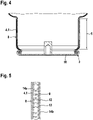
- Fig. 3 shows, in conjunction with figs. 4 and 5 , an embodiment of the air spring 1 in which a braided fabric 9 made of glass fiber materials is provided as additional wall reinforcement 4.1 of the rolling bellows 2, said braided fabric being configured on the outside of the customary reinforcing layers 12, 13, which are configured as woven fabric layers, and forming a composite material with the elastomer material of the bellows wall, including the elastomer layers 14a (top layer) and 14b (airtight inner layer / inner liner).
- the rolling bellows 2 is configured in the form of a tubular rolling bellows and is closed at both ends, namely at its upper end 6 with a metallic air spring cover 15 and at its lower end 3 with a metallic air spring base 16.
- the air connection 17, and also an ultrasound sensor 18 for measuring the height of the air spring is also located in the air spring cover 15.
- fig. 4 shows an enlarged sectional illustration of the lower part of the air spring illustrated in fig. 3 .
- Figure 5 shows an enlarged illustration of the wall construction of an air spring as shown in figure 3 and figure 4 .
- Fig. 6 shows, for comparison, an air spring 19 in cross section, as is customary in the prior art.
- the air spring 18 is composed substantially of an air spring bellows 20 which is connected to a cover 21 fastened at the upper end of said air spring bellows and to a separately produced air spring piston or rolling piston 22 fastened at the lower end of said air spring bellows.
- connection to the air spring cover occurs by flanging a bead ring formed at the upper end of the air spring bellows and having an inserted core wire
- connection to the rolling piston 22 is provided such that the lower end of the air spring bellows, said lower end being provided with a further bead ring, is pushed merely with a fit onto a rolling bellows seat 23, which is complementary thereto, of the piston 22.
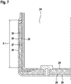
- Fig. 7 shows the lower part of a rolling bellows 24 of an air spring in half-section, with its end-side partial length 5.1, the rolling bellows also being configured here in the form of a tubular rolling bellows and being closed at its bellows end, which lies opposite the additional wall reinforcement 25 and which is not illustrated in any more detail here, with an air spring cover which is likewise not shown here.
- the additional wall reinforcement 25 at the first bellows end and proceeding from the circumference of the rolling bellows, continues in a radially inward direction in a pot-like manner and thus forms an air spring base.
- the customary reinforcing layers 26, 27 which are configured as woven fabric layers also continue in a radially inward direction over a short base region.
- the elastomer material of the bellows wall namely the top layer 28 and the airtight inner layer / the inner liner 29, likewise continues into the base region and there forms a sandwich material with the additional wall reinforcement.
Landscapes
- Engineering & Computer Science (AREA)
- General Engineering & Computer Science (AREA)
- Mechanical Engineering (AREA)
- Fluid-Damping Devices (AREA)
- Diaphragms And Bellows (AREA)
Abstract
Description
- The invention relates to an air spring with an air spring rolling bellows made of elastomer material with reinforcing layers embedded within the rolling bellows wall, the air spring being clamped in between a sprung and an unsprung mass.
- The use of air springs in vehicles is nowadays customary for reasons of the ride comfort and of the adjustable large travel stroke and is in particular the norm in the case of buses and lorries. Acceptance has finally been gained here of rolling bellows/tubular rolling bellows which have multilayer and possibly reinforced walls made of elastomer materials and which are fixedly connected or clamped at their ends to connection parts made of metal or plastic. These are customarily, on the one hand, an air spring cover and, on the other hand, an air spring piston on which the air spring bellows can roll in operation, that is to say during compression and extension, with the formation of a rolling fold.
- The air spring cover is as a rule connected to the vehicle body, that is to say the sprung mass, whereas the air spring piston is fastened to the chassis, that is to say to the unsprung mass. The air springs are connected to an air supply, customarily by means of hoses and/or air lines which, via corresponding connections and valves for air delivery and control on the air spring cover, are connected to the working space or pressure space within the air spring bellows. The air is supplied by way of a pressure accumulator located in the vehicle, which is filled by means of a compressor and then provides the supply of air for the individual sprung systems by way of a controller. The air-spring controller is often incorporated in the rest of the vehicle control system.
- The connection parts and the air spring bellows thus enclose the working space which is under internal pressure and contains the air spring volume and which is connected to the air connection which is often provided in the cover.
-
US 6,386,524 B1 discloses an air spring in which the customarily present construction of the connection between the air spring bellows and the connection parts becomes clear. Whereas the connection to the air spring cover occurs by crimping or flanging a bead ring formed at the upper end of the air spring bellows and having an inserted core wire, the connection to the rolling piston, which is here formed from plastic, is provided such that the lower end of the air spring bellows, said lower end being provided with a further bead ring, is pushed or pressed merely with a fit onto a seat, which is complementary thereto, of the piston. - The connection shown there between the air spring bellows and the piston disadvantageously requires complicated precisely tailored machining of the sealing surfaces and of the connection cross section on the piston and, on the other hand, is not secure during lifting of the vehicle since the piston can be pulled off the air spring bellows.
- To date, for the rolling movement, air springs with a rolling bellows thus require an air spring piston which is to be produced separately, that is to say a pot-shaped or cylindrical, dimensionally stable and rigid body whose cylindrical walls extend in a longitudinal direction of the rolling bellows, such that, during operation, the rolling bellows can roll on the outside of the walls, with the formation of a rolling fold.
- The object of the present invention was accordingly to provide an air spring of simplified construction, in the case of which it is possible to dispense with a separate rolling piston and thus a separate production of rolling pistons can be omitted, in the case of which the connection between the rolling bellows and the rolling piston, and thus fits with narrow tolerances in the connecting region, can also be omitted, and with which the assembly and the construction of chassis are simplified.
- This problem is solved by the features of the main claim. Further advantageous embodiments are disclosed in the dependent claims.
- In this case, the rolling bellows comprises, within its wall at a first bellows end, a tubular or cylindrical wall reinforcement which extends in a longitudinal direction of the rolling bellows and which is formed in addition to the customary reinforcing layers provided for the bellows wall, said wall reinforcement extending over an end-side partial length of the rolling bellows and imparting such a dimensional stability to the rolling bellows there that, during operation, the rolling bellows rolls, by way of its wall parts located outside of the additional wall reinforcement, on the outer side of the end-side partial length, with the formation of a rolling fold.
- By virtue of the inventive configuration of the rolling bellows in an air spring, as it were a rolling bellows with an "integrated piston" is provided in that specifically a partial region of the rolling bellows is configured in a dimensionally stable and cylindrical manner as a result of additional reinforcements and thus can assume the functions which traditionally and in the prior art are assumed by the rolling piston. Indeed, savings are thus made on components, their production and their transport, without adversely affecting the function of the air spring as rolling bellows spring.
- A major advantage during the assembly is naturally that the air spring bellows can be delivered to its place of use in a ready-to-install state and can be assembled there without the need to first establish a connection to a separate air spring piston. The air spring with the air spring bellows can thus be inserted into the chassis without further assembly steps and needs only to be correspondingly fastened to the connection parts.
- An advantageous development consists in that the additional wall reinforcement of the rolling bellows is composed of one or more tubular or cylindrical layers of reinforcing material, which form a sandwich structure with the material of the rolling bellows. In this case, the individual layers can be arranged in the center in relation to the wall thickness of the rolling bellows, on the inner side thereof or on the outer side.
- A further advantageous configuration consists in that the tubular or cylindrical layers of reinforcing material are layered into one another. Such a construction of cylinders layered into one another produces a particularly dimensionally stable and robust configuration of the relevant end region, that is to say the end-side partial length of the rolling bellows. With such a configuration, approximately the same dimensional stability is achieved on the rolling surface as could be provided by an air spring piston made of steel.
- A further advantageous configuration consists in that the additional wall reinforcement of the rolling bellows is formed of fiber materials, for instance glass fibers, carbon fibers or synthetic fibers, or is formed of composite materials reinforced with such fibers. As a result of corresponding arrangement and layering, it is possible to form any desired material strength or dimensional stability in a simple manner.
- A further advantageous configuration consists in that the rolling bellows is configured in the form of a tubular rolling bellows and is closed at one or both ends with an air spring cover or air spring base. Preferably, use is made of metallic covers or bases here, however covers or bases made of plastic have also already been tried. A lightweight construction with plastics materials is desired in many sectors. With said add-on parts, the air spring is ready to install and can be assembled with cover and base and connected to the air supply.
- An advantageous further configuration of the invention consists in that the rolling bellows is configured in the form of a tubular rolling bellows and is closed at its second bellows end, which lies opposite the additional wall reinforcement, with an air spring cover, and, in said bellows, the additional wall reinforcement, at the first bellows end and proceeding from the circumference of the rolling bellows, continues in a radially inward direction in a pot-like manner and forms an air spring base, the entire sandwich structure preferably continuing in a radially inward direction.
- Since the additional reinforcements can be produced in any form, particularly if they are formed of layer materials or composite materials, it is thus also possible to use them to close the air spring bellows for example on its lower side. This is possible in that a pot-like configuration results only in one fastening edge, to which further components, for example a simple base plate, can be connected. However, it is equally possible for the base itself to be produced from the composite material or from the layer materials.
- The air spring according to the invention, on account of its simple and integrated construction and its easy assembly, is particularly suitable for chassis of a car or commercial vehicle.
- The invention will be explained in more detail on the basis of an exemplary embodiment. In the figures:
- fig. 1
- shows an air spring according to the invention for a heavy goods vehicle in the extended state, in cross section,
- fig. 2
- shows the air spring as shown in
fig. 1 in the compressed position/in the operating state, in cross section, - figs. 3 - 5
- show a further embodiment of the air spring according to the invention with an additional wall reinforcement made of glass fiber materials,
- fig. 6
- shows an air spring from the prior art with separate rolling piston for comparison,
- fig. 7
- shows the further embodiment of the air spring according to the invention.
-
Fig. 1 shows an air spring 1 according to the invention for a heavy goods vehicle having a rollingbellows 2 made of elastomer material in the extended state, in cross section. The air spring is customarily clamped in between a sprung and an unsprung mass, namely between the body of the heavy goods vehicle and the associated chassis. Sprung and unsprung masses, that is to say the body and chassis, are not illustrated in more detail here in order to keep the exemplary embodiment as clear as possible and to illustrate only essential features of the invention. - The
rolling bellows 2 configured in the form of a tubular rolling bellows comprises, at itslower bellows end 3, within its wall, a tubular orcylindrical wall reinforcement 4 which extends in a longitudinal direction of the rolling bellows and which is formed in addition to the "customary" reinforcing layers which, for the sake of clarity, are not illustrated in any more detail here infigs. 1 and 2 , said wall reinforcement extending over an end-sidepartial length 5 of the rolling bellows. Saidpartial length 5 corresponds approximately to the customary height of a rolling piston from the prior art. -
Fig. 2 shows the same air spring fromfig. 1 for a heavy goods vehicle in the compressed position, that is to say in an operating state, in cross section. The tubular orcylindrical wall reinforcement 4 extending over the end-sidepartial length 5 of the rolling bellows imparts such a dimensional stability to the rolling bellows there that, during operation, therolling bellows 2 rolls, by way of its wall parts 10 located outside of the additional wall reinforcement, on theouter surface 8 of the end-sidepartial length 5, with the formation of a rolling fold 7. The compression and extension of the air spring 1 during operation is illustrated here by themovement arrow 11. -
Fig. 3 shows, in conjunction withfigs. 4 and 5 , an embodiment of the air spring 1 in which a braided fabric 9 made of glass fiber materials is provided as additional wall reinforcement 4.1 of therolling bellows 2, said braided fabric being configured on the outside of thecustomary reinforcing layers elastomer layers 14a (top layer) and 14b (airtight inner layer / inner liner). Therolling bellows 2 is configured in the form of a tubular rolling bellows and is closed at both ends, namely at itsupper end 6 with a metallicair spring cover 15 and at itslower end 3 with a metallicair spring base 16. Theair connection 17, and also anultrasound sensor 18 for measuring the height of the air spring, is also located in theair spring cover 15. - In this case,
fig. 4 shows an enlarged sectional illustration of the lower part of the air spring illustrated infig. 3 .Figure 5 shows an enlarged illustration of the wall construction of an air spring as shown infigure 3 andfigure 4 . -
Fig. 6 shows, for comparison, anair spring 19 in cross section, as is customary in the prior art. Theair spring 18 is composed substantially of an air spring bellows 20 which is connected to acover 21 fastened at the upper end of said air spring bellows and to a separately produced air spring piston or rollingpiston 22 fastened at the lower end of said air spring bellows. Whereas the connection to the air spring cover occurs by flanging a bead ring formed at the upper end of the air spring bellows and having an inserted core wire, the connection to the rollingpiston 22 is provided such that the lower end of the air spring bellows, said lower end being provided with a further bead ring, is pushed merely with a fit onto a rolling bellowsseat 23, which is complementary thereto, of thepiston 22. Both the outlay for producing separate parts (air spring bellows and rolling piston) and the outlay for assembly and installation are significantly greater in the case of such an air spring from the prior art than in the case of the solution according to the invention. -
Fig. 7 shows the lower part of a rolling bellows 24 of an air spring in half-section, with its end-side partial length 5.1, the rolling bellows also being configured here in the form of a tubular rolling bellows and being closed at its bellows end, which lies opposite theadditional wall reinforcement 25 and which is not illustrated in any more detail here, with an air spring cover which is likewise not shown here. - In the lower part of the rolling bellows 24 shown here, the
additional wall reinforcement 25, at the first bellows end and proceeding from the circumference of the rolling bellows, continues in a radially inward direction in a pot-like manner and thus forms an air spring base. In this case, the customary reinforcinglayers top layer 28 and the airtight inner layer / theinner liner 29, likewise continues into the base region and there forms a sandwich material with the additional wall reinforcement. -
- 1
- Air spring
- 2
- Rolling bellows, air spring rolling bellows, tubular rolling bellows
- 3
- Lower bellows end of the rolling bellows, first bellows end
- 4
- Additional wall reinforcement
- 4.1
- Additional wall reinforcement made of glass fiber braided fabric
- 5
- End-side partial length of the rolling bellows, rolling region
- 5.1
- End-side partial length of the rolling bellows, rolling region
- 6
- Upper, second bellows end
- 7
- Rolling fold
- 8
- Outer surface of the end-side partial length, rolling face
- 9
- Glass fiber braided fabric
- 10
- Wall outside of the additional wall reinforcement
- 11
- Spring movement during compression and extension in operation
- 12
- Reinforcing layer / reinforcing woven fabric of customary type
- 13
- Reinforcing layer / reinforcing woven fabric of customary type
- 14
- Elastomer matrix
- 14a
- Outer top layer of the air spring bellows wall
- 14b
- Inner airtight layer of the air spring bellows wall
- 15
- Air spring cover
- 16
- Air spring base
- 17
- Air connection
- 18
- Ultrasound sensor
- 19
- Air spring (prior art)
- 20
- Air spring bellows (prior art)
- 21
- Air spring cover (prior art)
- 22
- Air spring piston / rolling piston (prior art)
- 23
- Rolling bellows seat on the piston (prior art)
- 24
- Air spring bellows
- 25
- Additional wall reinforcement
- 26
- Customary reinforcing layer
- 27
- Customary reinforcing layer
- 28
- Top layer (elastomer)
- 29
- Airtight inner layer
Claims (7)
- An air spring (1) with an air spring rolling bellows (2) made of elastomer material with reinforcing layers embedded within the rolling bellows wall, the air spring being clamped in between a sprung and an unsprung mass, wherein the rolling bellows (2) comprises, within its wall at a first bellows end (3), a tubular or cylindrical wall reinforcement (4, 4.1, 25) which extends in a longitudinal direction of the rolling bellows (2) and which is formed in addition to the reinforcing layers, said wall reinforcement extending over an end-side partial length (5) of the rolling bellows (2) and imparting such a dimensional stability to the rolling bellows there that, during operation, the rolling bellows (2) rolls, by way of its wall parts (10) located outside of the additional wall reinforcement, on the outer surface (8) of the end-side partial length (5), with the formation of a rolling fold (7).
- The air spring as claimed in claim 1, in which the additional wall reinforcement (4, 4.1, 25) of the rolling bellows (2) is composed of one or more tubular or cylindrical layers of reinforcing material (9), which form a sandwich structure with the material (14a, 14b, 28, 29) of the rolling bellows.
- The air spring as claimed in claim 2, in which the tubular or cylindrical layers of reinforcing material (9) are layered into one another.
- The air spring as claimed in one of claims 1 to 3, in which the additional wall reinforcement of the rolling bellows (2) is formed of fiber materials (9) or fiber-reinforced composite materials.
- The air spring as claimed in one of claims 1 to 4, in which the rolling bellows (2) is configured in the form of a tubular rolling bellows and is closed at one or both ends (3, 6) with an air spring cover (15) or air spring base (16).
- The air spring as claimed in one of claims 1 to 5, in which the rolling bellows (2) is configured in the form of a tubular rolling bellows and is closed at its second bellows end (6), which lies opposite the additional wall reinforcement, with an air spring cover, and, in said bellows, the additional wall reinforcement (25), at the first bellows end and proceeding from the circumference of the rolling bellows, continues in a radially inward direction in a pot-like manner and forms an air spring base, the entire sandwich structure preferably continuing in a radially inward direction.
- A chassis of a car or commercial vehicle having an air spring as claimed in one of claims 1 to 6.
Priority Applications (2)
| Application Number | Priority Date | Filing Date | Title |
|---|---|---|---|
| EP20200875.1A EP3982003B1 (en) | 2020-10-08 | 2020-10-08 | Air spring |
| PCT/EP2021/076154 WO2022073769A1 (en) | 2020-10-08 | 2021-09-23 | Air spring |
Applications Claiming Priority (1)
| Application Number | Priority Date | Filing Date | Title |
|---|---|---|---|
| EP20200875.1A EP3982003B1 (en) | 2020-10-08 | 2020-10-08 | Air spring |
Publications (2)
| Publication Number | Publication Date |
|---|---|
| EP3982003A1 true EP3982003A1 (en) | 2022-04-13 |
| EP3982003B1 EP3982003B1 (en) | 2023-08-02 |
Family
ID=72811748
Family Applications (1)
| Application Number | Title | Priority Date | Filing Date |
|---|---|---|---|
| EP20200875.1A Active EP3982003B1 (en) | 2020-10-08 | 2020-10-08 | Air spring |
Country Status (2)
| Country | Link |
|---|---|
| EP (1) | EP3982003B1 (en) |
| WO (1) | WO2022073769A1 (en) |
Citations (3)
| Publication number | Priority date | Publication date | Assignee | Title |
|---|---|---|---|---|
| US5346187A (en) * | 1990-03-24 | 1994-09-13 | Continental Aktiengesellschaft | Roll bellows-type pneumatic shock absorber having a reinforced roll bellows |
| US6386524B1 (en) | 2000-02-15 | 2002-05-14 | Bfs Diversified Products, Llc | Pedestal mounted full reservoir air spring piston |
| DE102008017703A1 (en) * | 2008-04-08 | 2009-10-22 | Knorr-Bremse Systeme für Nutzfahrzeuge GmbH | Spring bellows comprises adjustment unit, which is formed to reduce inner volume of spring bellows, and to increase spring rigidity of spring bellows, and spring bellows comprises effective bearing surface and bellows height |
-
2020
- 2020-10-08 EP EP20200875.1A patent/EP3982003B1/en active Active
-
2021
- 2021-09-23 WO PCT/EP2021/076154 patent/WO2022073769A1/en not_active Ceased
Patent Citations (3)
| Publication number | Priority date | Publication date | Assignee | Title |
|---|---|---|---|---|
| US5346187A (en) * | 1990-03-24 | 1994-09-13 | Continental Aktiengesellschaft | Roll bellows-type pneumatic shock absorber having a reinforced roll bellows |
| US6386524B1 (en) | 2000-02-15 | 2002-05-14 | Bfs Diversified Products, Llc | Pedestal mounted full reservoir air spring piston |
| DE102008017703A1 (en) * | 2008-04-08 | 2009-10-22 | Knorr-Bremse Systeme für Nutzfahrzeuge GmbH | Spring bellows comprises adjustment unit, which is formed to reduce inner volume of spring bellows, and to increase spring rigidity of spring bellows, and spring bellows comprises effective bearing surface and bellows height |
Also Published As
| Publication number | Publication date |
|---|---|
| EP3982003B1 (en) | 2023-08-02 |
| WO2022073769A1 (en) | 2022-04-14 |
Similar Documents
| Publication | Publication Date | Title |
|---|---|---|
| US8474798B2 (en) | Air spring for vehicle | |
| CN106536237B (en) | Suspension system and method of operating the same | |
| EP2170634B1 (en) | Jounce bumper assembly and gas spring assembly including same | |
| US9127737B2 (en) | Unreinforced elastomeric spring wall, gas spring and method | |
| EP4010210B1 (en) | Mounting assemblies as well as gas spring and damper assemblies and suspension systems including same | |
| US5180146A (en) | Rolling piston for a roll bellows of a roll bellows-type pneumatic shock absorber | |
| US9694642B2 (en) | Seal arrangement for an air spring system | |
| US11554624B2 (en) | Gas spring and gas damper assemblies as well as suspension systems and methods including the same | |
| CN102834640B (en) | Air spring | |
| US11760146B2 (en) | Pressure body for a compressed-air system | |
| EP3982003B1 (en) | Air spring | |
| CN112879485A (en) | Air suspension assembly and bellows for an air suspension assembly | |
| US7766136B2 (en) | Suspension arrangement for motor vehicles | |
| GB2456750A (en) | A rolling diaphragm air spring | |
| US11999207B2 (en) | Air springs and methods for making the same | |
| EP3926203A1 (en) | Air spring | |
| CN103104647A (en) | Vibration damper for suspension strut of motor vehicle, has supporting ring which is formed with radially directed flange | |
| US7832747B2 (en) | Car body for a motor vehicle | |
| EP4008572B1 (en) | Air spring | |
| JP2024174828A (en) | Sleeve for vehicle air spring and vehicle air spring including same | |
| CN121241210A (en) | A gas spring assembly with an internal rebound limiting component and a suspension system including the gas spring assembly. | |
| WO2024232938A1 (en) | Jounce bumper assemblies and gas spring assemblies including same |
Legal Events
| Date | Code | Title | Description |
|---|---|---|---|
| PUAI | Public reference made under article 153(3) epc to a published international application that has entered the european phase |
Free format text: ORIGINAL CODE: 0009012 |
|
| STAA | Information on the status of an ep patent application or granted ep patent |
Free format text: STATUS: THE APPLICATION HAS BEEN PUBLISHED |
|
| AK | Designated contracting states |
Kind code of ref document: A1 Designated state(s): AL AT BE BG CH CY CZ DE DK EE ES FI FR GB GR HR HU IE IS IT LI LT LU LV MC MK MT NL NO PL PT RO RS SE SI SK SM TR |
|
| STAA | Information on the status of an ep patent application or granted ep patent |
Free format text: STATUS: REQUEST FOR EXAMINATION WAS MADE |
|
| 17P | Request for examination filed |
Effective date: 20221013 |
|
| RBV | Designated contracting states (corrected) |
Designated state(s): AL AT BE BG CH CY CZ DE DK EE ES FI FR GB GR HR HU IE IS IT LI LT LU LV MC MK MT NL NO PL PT RO RS SE SI SK SM TR |
|
| GRAP | Despatch of communication of intention to grant a patent |
Free format text: ORIGINAL CODE: EPIDOSNIGR1 |
|
| STAA | Information on the status of an ep patent application or granted ep patent |
Free format text: STATUS: GRANT OF PATENT IS INTENDED |
|
| INTG | Intention to grant announced |
Effective date: 20230224 |
|
| RIN1 | Information on inventor provided before grant (corrected) |
Inventor name: SZLAVIK, TAMAS Inventor name: HORNYAK, LASZLO Inventor name: DUMAN, GUERAY Inventor name: OMAN, SIMON Inventor name: HANSEN, CARSTEN Inventor name: BOSCH-MASGRAU, FRANCESC Inventor name: STOJKO, BRANE Inventor name: KOSIR, MATEJ Inventor name: HEBERLE, PETER Inventor name: JANHAR, ZIGA |
|
| GRAS | Grant fee paid |
Free format text: ORIGINAL CODE: EPIDOSNIGR3 |
|
| GRAA | (expected) grant |
Free format text: ORIGINAL CODE: 0009210 |
|
| STAA | Information on the status of an ep patent application or granted ep patent |
Free format text: STATUS: THE PATENT HAS BEEN GRANTED |
|
| P01 | Opt-out of the competence of the unified patent court (upc) registered |
Effective date: 20230602 |
|
| AK | Designated contracting states |
Kind code of ref document: B1 Designated state(s): AL AT BE BG CH CY CZ DE DK EE ES FI FR GB GR HR HU IE IS IT LI LT LU LV MC MK MT NL NO PL PT RO RS SE SI SK SM TR |
|
| REG | Reference to a national code |
Ref country code: GB Ref legal event code: FG4D |
|
| REG | Reference to a national code |
Ref country code: CH Ref legal event code: EP |
|
| REG | Reference to a national code |
Ref country code: DE Ref legal event code: R096 Ref document number: 602020014832 Country of ref document: DE |
|
| REG | Reference to a national code |
Ref country code: IE Ref legal event code: FG4D |
|
| REG | Reference to a national code |
Ref country code: LT Ref legal event code: MG9D |
|
| REG | Reference to a national code |
Ref country code: NL Ref legal event code: MP Effective date: 20230802 |
|
| RAP2 | Party data changed (patent owner data changed or rights of a patent transferred) |
Owner name: CONTITECH DEUTSCHLAND GMBH |
|
| REG | Reference to a national code |
Ref country code: AT Ref legal event code: MK05 Ref document number: 1595089 Country of ref document: AT Kind code of ref document: T Effective date: 20230802 |
|
| PG25 | Lapsed in a contracting state [announced via postgrant information from national office to epo] |
Ref country code: GR Free format text: LAPSE BECAUSE OF FAILURE TO SUBMIT A TRANSLATION OF THE DESCRIPTION OR TO PAY THE FEE WITHIN THE PRESCRIBED TIME-LIMIT Effective date: 20231103 |
|
| PG25 | Lapsed in a contracting state [announced via postgrant information from national office to epo] |
Ref country code: IS Free format text: LAPSE BECAUSE OF FAILURE TO SUBMIT A TRANSLATION OF THE DESCRIPTION OR TO PAY THE FEE WITHIN THE PRESCRIBED TIME-LIMIT Effective date: 20231202 |
|
| PG25 | Lapsed in a contracting state [announced via postgrant information from national office to epo] |
Ref country code: SE Free format text: LAPSE BECAUSE OF FAILURE TO SUBMIT A TRANSLATION OF THE DESCRIPTION OR TO PAY THE FEE WITHIN THE PRESCRIBED TIME-LIMIT Effective date: 20230802 Ref country code: RS Free format text: LAPSE BECAUSE OF FAILURE TO SUBMIT A TRANSLATION OF THE DESCRIPTION OR TO PAY THE FEE WITHIN THE PRESCRIBED TIME-LIMIT Effective date: 20230802 Ref country code: PT Free format text: LAPSE BECAUSE OF FAILURE TO SUBMIT A TRANSLATION OF THE DESCRIPTION OR TO PAY THE FEE WITHIN THE PRESCRIBED TIME-LIMIT Effective date: 20231204 Ref country code: NO Free format text: LAPSE BECAUSE OF FAILURE TO SUBMIT A TRANSLATION OF THE DESCRIPTION OR TO PAY THE FEE WITHIN THE PRESCRIBED TIME-LIMIT Effective date: 20231102 Ref country code: NL Free format text: LAPSE BECAUSE OF FAILURE TO SUBMIT A TRANSLATION OF THE DESCRIPTION OR TO PAY THE FEE WITHIN THE PRESCRIBED TIME-LIMIT Effective date: 20230802 Ref country code: LV Free format text: LAPSE BECAUSE OF FAILURE TO SUBMIT A TRANSLATION OF THE DESCRIPTION OR TO PAY THE FEE WITHIN THE PRESCRIBED TIME-LIMIT Effective date: 20230802 Ref country code: LT Free format text: LAPSE BECAUSE OF FAILURE TO SUBMIT A TRANSLATION OF THE DESCRIPTION OR TO PAY THE FEE WITHIN THE PRESCRIBED TIME-LIMIT Effective date: 20230802 Ref country code: IS Free format text: LAPSE BECAUSE OF FAILURE TO SUBMIT A TRANSLATION OF THE DESCRIPTION OR TO PAY THE FEE WITHIN THE PRESCRIBED TIME-LIMIT Effective date: 20231202 Ref country code: HR Free format text: LAPSE BECAUSE OF FAILURE TO SUBMIT A TRANSLATION OF THE DESCRIPTION OR TO PAY THE FEE WITHIN THE PRESCRIBED TIME-LIMIT Effective date: 20230802 Ref country code: GR Free format text: LAPSE BECAUSE OF FAILURE TO SUBMIT A TRANSLATION OF THE DESCRIPTION OR TO PAY THE FEE WITHIN THE PRESCRIBED TIME-LIMIT Effective date: 20231103 Ref country code: FI Free format text: LAPSE BECAUSE OF FAILURE TO SUBMIT A TRANSLATION OF THE DESCRIPTION OR TO PAY THE FEE WITHIN THE PRESCRIBED TIME-LIMIT Effective date: 20230802 Ref country code: AT Free format text: LAPSE BECAUSE OF FAILURE TO SUBMIT A TRANSLATION OF THE DESCRIPTION OR TO PAY THE FEE WITHIN THE PRESCRIBED TIME-LIMIT Effective date: 20230802 |
|
| PG25 | Lapsed in a contracting state [announced via postgrant information from national office to epo] |
Ref country code: PL Free format text: LAPSE BECAUSE OF FAILURE TO SUBMIT A TRANSLATION OF THE DESCRIPTION OR TO PAY THE FEE WITHIN THE PRESCRIBED TIME-LIMIT Effective date: 20230802 |
|
| REG | Reference to a national code |
Ref country code: DE Ref legal event code: R081 Ref document number: 602020014832 Country of ref document: DE Owner name: CONTITECH DEUTSCHLAND GMBH, DE Free format text: FORMER OWNER: CONTITECH AG, 30165 HANNOVER, DE |
|
| PG25 | Lapsed in a contracting state [announced via postgrant information from national office to epo] |
Ref country code: ES Free format text: LAPSE BECAUSE OF FAILURE TO SUBMIT A TRANSLATION OF THE DESCRIPTION OR TO PAY THE FEE WITHIN THE PRESCRIBED TIME-LIMIT Effective date: 20230802 |
|
| PG25 | Lapsed in a contracting state [announced via postgrant information from national office to epo] |
Ref country code: SM Free format text: LAPSE BECAUSE OF FAILURE TO SUBMIT A TRANSLATION OF THE DESCRIPTION OR TO PAY THE FEE WITHIN THE PRESCRIBED TIME-LIMIT Effective date: 20230802 Ref country code: RO Free format text: LAPSE BECAUSE OF FAILURE TO SUBMIT A TRANSLATION OF THE DESCRIPTION OR TO PAY THE FEE WITHIN THE PRESCRIBED TIME-LIMIT Effective date: 20230802 Ref country code: ES Free format text: LAPSE BECAUSE OF FAILURE TO SUBMIT A TRANSLATION OF THE DESCRIPTION OR TO PAY THE FEE WITHIN THE PRESCRIBED TIME-LIMIT Effective date: 20230802 Ref country code: EE Free format text: LAPSE BECAUSE OF FAILURE TO SUBMIT A TRANSLATION OF THE DESCRIPTION OR TO PAY THE FEE WITHIN THE PRESCRIBED TIME-LIMIT Effective date: 20230802 Ref country code: DK Free format text: LAPSE BECAUSE OF FAILURE TO SUBMIT A TRANSLATION OF THE DESCRIPTION OR TO PAY THE FEE WITHIN THE PRESCRIBED TIME-LIMIT Effective date: 20230802 Ref country code: CZ Free format text: LAPSE BECAUSE OF FAILURE TO SUBMIT A TRANSLATION OF THE DESCRIPTION OR TO PAY THE FEE WITHIN THE PRESCRIBED TIME-LIMIT Effective date: 20230802 Ref country code: SK Free format text: LAPSE BECAUSE OF FAILURE TO SUBMIT A TRANSLATION OF THE DESCRIPTION OR TO PAY THE FEE WITHIN THE PRESCRIBED TIME-LIMIT Effective date: 20230802 |
|
| REG | Reference to a national code |
Ref country code: DE Ref legal event code: R097 Ref document number: 602020014832 Country of ref document: DE |
|
| PG25 | Lapsed in a contracting state [announced via postgrant information from national office to epo] |
Ref country code: IT Free format text: LAPSE BECAUSE OF FAILURE TO SUBMIT A TRANSLATION OF THE DESCRIPTION OR TO PAY THE FEE WITHIN THE PRESCRIBED TIME-LIMIT Effective date: 20230802 Ref country code: MC Free format text: LAPSE BECAUSE OF FAILURE TO SUBMIT A TRANSLATION OF THE DESCRIPTION OR TO PAY THE FEE WITHIN THE PRESCRIBED TIME-LIMIT Effective date: 20230802 |
|
| REG | Reference to a national code |
Ref country code: CH Ref legal event code: PL |
|
| PLBE | No opposition filed within time limit |
Free format text: ORIGINAL CODE: 0009261 |
|
| STAA | Information on the status of an ep patent application or granted ep patent |
Free format text: STATUS: NO OPPOSITION FILED WITHIN TIME LIMIT |
|
| REG | Reference to a national code |
Ref country code: BE Ref legal event code: MM Effective date: 20231031 |
|
| PG25 | Lapsed in a contracting state [announced via postgrant information from national office to epo] |
Ref country code: LU Free format text: LAPSE BECAUSE OF NON-PAYMENT OF DUE FEES Effective date: 20231008 |
|
| PG25 | Lapsed in a contracting state [announced via postgrant information from national office to epo] |
Ref country code: LU Free format text: LAPSE BECAUSE OF NON-PAYMENT OF DUE FEES Effective date: 20231008 |
|
| 26N | No opposition filed |
Effective date: 20240503 |
|
| PG25 | Lapsed in a contracting state [announced via postgrant information from national office to epo] |
Ref country code: CH Free format text: LAPSE BECAUSE OF NON-PAYMENT OF DUE FEES Effective date: 20231031 |
|
| PG25 | Lapsed in a contracting state [announced via postgrant information from national office to epo] |
Ref country code: CH Free format text: LAPSE BECAUSE OF NON-PAYMENT OF DUE FEES Effective date: 20231031 Ref country code: SI Free format text: LAPSE BECAUSE OF FAILURE TO SUBMIT A TRANSLATION OF THE DESCRIPTION OR TO PAY THE FEE WITHIN THE PRESCRIBED TIME-LIMIT Effective date: 20230802 |
|
| PG25 | Lapsed in a contracting state [announced via postgrant information from national office to epo] |
Ref country code: BE Free format text: LAPSE BECAUSE OF NON-PAYMENT OF DUE FEES Effective date: 20231031 |
|
| PG25 | Lapsed in a contracting state [announced via postgrant information from national office to epo] |
Ref country code: IE Free format text: LAPSE BECAUSE OF NON-PAYMENT OF DUE FEES Effective date: 20231008 |
|
| PG25 | Lapsed in a contracting state [announced via postgrant information from national office to epo] |
Ref country code: IE Free format text: LAPSE BECAUSE OF NON-PAYMENT OF DUE FEES Effective date: 20231008 |
|
| PG25 | Lapsed in a contracting state [announced via postgrant information from national office to epo] |
Ref country code: BG Free format text: LAPSE BECAUSE OF FAILURE TO SUBMIT A TRANSLATION OF THE DESCRIPTION OR TO PAY THE FEE WITHIN THE PRESCRIBED TIME-LIMIT Effective date: 20230802 |
|
| PG25 | Lapsed in a contracting state [announced via postgrant information from national office to epo] |
Ref country code: BG Free format text: LAPSE BECAUSE OF FAILURE TO SUBMIT A TRANSLATION OF THE DESCRIPTION OR TO PAY THE FEE WITHIN THE PRESCRIBED TIME-LIMIT Effective date: 20230802 |
|
| PG25 | Lapsed in a contracting state [announced via postgrant information from national office to epo] |
Ref country code: CY Free format text: LAPSE BECAUSE OF FAILURE TO SUBMIT A TRANSLATION OF THE DESCRIPTION OR TO PAY THE FEE WITHIN THE PRESCRIBED TIME-LIMIT; INVALID AB INITIO Effective date: 20201008 |
|
| PG25 | Lapsed in a contracting state [announced via postgrant information from national office to epo] |
Ref country code: HU Free format text: LAPSE BECAUSE OF FAILURE TO SUBMIT A TRANSLATION OF THE DESCRIPTION OR TO PAY THE FEE WITHIN THE PRESCRIBED TIME-LIMIT; INVALID AB INITIO Effective date: 20201008 |
|
| PGFP | Annual fee paid to national office [announced via postgrant information from national office to epo] |
Ref country code: TR Payment date: 20250930 Year of fee payment: 6 |
|
| PGFP | Annual fee paid to national office [announced via postgrant information from national office to epo] |
Ref country code: DE Payment date: 20251031 Year of fee payment: 6 |
|
| PGFP | Annual fee paid to national office [announced via postgrant information from national office to epo] |
Ref country code: GB Payment date: 20251022 Year of fee payment: 6 |
|
| PGFP | Annual fee paid to national office [announced via postgrant information from national office to epo] |
Ref country code: FR Payment date: 20251030 Year of fee payment: 6 |