EP3981997A1 - Reverse-input-blocking clutch - Google Patents
Reverse-input-blocking clutch Download PDFInfo
- Publication number
- EP3981997A1 EP3981997A1 EP20917248.5A EP20917248A EP3981997A1 EP 3981997 A1 EP3981997 A1 EP 3981997A1 EP 20917248 A EP20917248 A EP 20917248A EP 3981997 A1 EP3981997 A1 EP 3981997A1
- Authority
- EP
- European Patent Office
- Prior art keywords
- input
- output
- pair
- pressed surface
- engaging
- Prior art date
- Legal status (The legal status is an assumption and is not a legal conclusion. Google has not performed a legal analysis and makes no representation as to the accuracy of the status listed.)
- Granted
Links
Images





Classifications
-
- F—MECHANICAL ENGINEERING; LIGHTING; HEATING; WEAPONS; BLASTING
- F16—ENGINEERING ELEMENTS AND UNITS; GENERAL MEASURES FOR PRODUCING AND MAINTAINING EFFECTIVE FUNCTIONING OF MACHINES OR INSTALLATIONS; THERMAL INSULATION IN GENERAL
- F16D—COUPLINGS FOR TRANSMITTING ROTATION; CLUTCHES; BRAKES
- F16D41/00—Freewheels or freewheel clutches
- F16D41/04—Freewheels or freewheel clutches combined with a clutch for locking the driving and driven members
-
- F—MECHANICAL ENGINEERING; LIGHTING; HEATING; WEAPONS; BLASTING
- F16—ENGINEERING ELEMENTS AND UNITS; GENERAL MEASURES FOR PRODUCING AND MAINTAINING EFFECTIVE FUNCTIONING OF MACHINES OR INSTALLATIONS; THERMAL INSULATION IN GENERAL
- F16D—COUPLINGS FOR TRANSMITTING ROTATION; CLUTCHES; BRAKES
- F16D43/00—Automatic clutches
- F16D43/02—Automatic clutches actuated entirely mechanically
-
- F—MECHANICAL ENGINEERING; LIGHTING; HEATING; WEAPONS; BLASTING
- F16—ENGINEERING ELEMENTS AND UNITS; GENERAL MEASURES FOR PRODUCING AND MAINTAINING EFFECTIVE FUNCTIONING OF MACHINES OR INSTALLATIONS; THERMAL INSULATION IN GENERAL
- F16D—COUPLINGS FOR TRANSMITTING ROTATION; CLUTCHES; BRAKES
- F16D3/00—Yielding couplings, i.e. with means permitting movement between the connected parts during the drive
- F16D3/02—Yielding couplings, i.e. with means permitting movement between the connected parts during the drive adapted to specific functions
-
- F—MECHANICAL ENGINEERING; LIGHTING; HEATING; WEAPONS; BLASTING
- F16—ENGINEERING ELEMENTS AND UNITS; GENERAL MEASURES FOR PRODUCING AND MAINTAINING EFFECTIVE FUNCTIONING OF MACHINES OR INSTALLATIONS; THERMAL INSULATION IN GENERAL
- F16D—COUPLINGS FOR TRANSMITTING ROTATION; CLUTCHES; BRAKES
- F16D3/00—Yielding couplings, i.e. with means permitting movement between the connected parts during the drive
- F16D3/50—Yielding couplings, i.e. with means permitting movement between the connected parts during the drive with the coupling parts connected by one or more intermediate members
-
- F—MECHANICAL ENGINEERING; LIGHTING; HEATING; WEAPONS; BLASTING
- F16—ENGINEERING ELEMENTS AND UNITS; GENERAL MEASURES FOR PRODUCING AND MAINTAINING EFFECTIVE FUNCTIONING OF MACHINES OR INSTALLATIONS; THERMAL INSULATION IN GENERAL
- F16D—COUPLINGS FOR TRANSMITTING ROTATION; CLUTCHES; BRAKES
- F16D51/00—Brakes with outwardly-movable braking members co-operating with the inner surface of a drum or the like
- F16D51/16—Brakes with outwardly-movable braking members co-operating with the inner surface of a drum or the like shaped as brake-shoes pivoted on a fixed or nearly-fixed axis
- F16D51/18—Brakes with outwardly-movable braking members co-operating with the inner surface of a drum or the like shaped as brake-shoes pivoted on a fixed or nearly-fixed axis with two brake-shoes
-
- F—MECHANICAL ENGINEERING; LIGHTING; HEATING; WEAPONS; BLASTING
- F16—ENGINEERING ELEMENTS AND UNITS; GENERAL MEASURES FOR PRODUCING AND MAINTAINING EFFECTIVE FUNCTIONING OF MACHINES OR INSTALLATIONS; THERMAL INSULATION IN GENERAL
- F16D—COUPLINGS FOR TRANSMITTING ROTATION; CLUTCHES; BRAKES
- F16D51/00—Brakes with outwardly-movable braking members co-operating with the inner surface of a drum or the like
- F16D51/16—Brakes with outwardly-movable braking members co-operating with the inner surface of a drum or the like shaped as brake-shoes pivoted on a fixed or nearly-fixed axis
- F16D51/18—Brakes with outwardly-movable braking members co-operating with the inner surface of a drum or the like shaped as brake-shoes pivoted on a fixed or nearly-fixed axis with two brake-shoes
- F16D51/20—Brakes with outwardly-movable braking members co-operating with the inner surface of a drum or the like shaped as brake-shoes pivoted on a fixed or nearly-fixed axis with two brake-shoes extending in opposite directions from their pivots
- F16D51/22—Brakes with outwardly-movable braking members co-operating with the inner surface of a drum or the like shaped as brake-shoes pivoted on a fixed or nearly-fixed axis with two brake-shoes extending in opposite directions from their pivots mechanically actuated
-
- F—MECHANICAL ENGINEERING; LIGHTING; HEATING; WEAPONS; BLASTING
- F16—ENGINEERING ELEMENTS AND UNITS; GENERAL MEASURES FOR PRODUCING AND MAINTAINING EFFECTIVE FUNCTIONING OF MACHINES OR INSTALLATIONS; THERMAL INSULATION IN GENERAL
- F16D—COUPLINGS FOR TRANSMITTING ROTATION; CLUTCHES; BRAKES
- F16D51/00—Brakes with outwardly-movable braking members co-operating with the inner surface of a drum or the like
- F16D51/46—Self-tightening brakes with pivoted brake shoes, i.e. the braked member increases the braking action
- F16D51/48—Self-tightening brakes with pivoted brake shoes, i.e. the braked member increases the braking action with two linked or directly-interacting brake shoes
- F16D51/50—Self-tightening brakes with pivoted brake shoes, i.e. the braked member increases the braking action with two linked or directly-interacting brake shoes mechanically actuated
-
- F—MECHANICAL ENGINEERING; LIGHTING; HEATING; WEAPONS; BLASTING
- F16—ENGINEERING ELEMENTS AND UNITS; GENERAL MEASURES FOR PRODUCING AND MAINTAINING EFFECTIVE FUNCTIONING OF MACHINES OR INSTALLATIONS; THERMAL INSULATION IN GENERAL
- F16D—COUPLINGS FOR TRANSMITTING ROTATION; CLUTCHES; BRAKES
- F16D65/00—Parts or details
- F16D65/14—Actuating mechanisms for brakes; Means for initiating operation at a predetermined position
- F16D65/16—Actuating mechanisms for brakes; Means for initiating operation at a predetermined position arranged in or on the brake
- F16D65/22—Actuating mechanisms for brakes; Means for initiating operation at a predetermined position arranged in or on the brake adapted for pressing members apart, e.g. for drum brakes
-
- F—MECHANICAL ENGINEERING; LIGHTING; HEATING; WEAPONS; BLASTING
- F16—ENGINEERING ELEMENTS AND UNITS; GENERAL MEASURES FOR PRODUCING AND MAINTAINING EFFECTIVE FUNCTIONING OF MACHINES OR INSTALLATIONS; THERMAL INSULATION IN GENERAL
- F16D—COUPLINGS FOR TRANSMITTING ROTATION; CLUTCHES; BRAKES
- F16D67/00—Combinations of couplings and brakes; Combinations of clutches and brakes
- F16D67/02—Clutch-brake combinations
Definitions
- the present invention relates to a reverse input cutoff clutch that transmits rotational torque input to an input member to an output member, while completely blocking rotational torque that is reversely input to the output member so as not to transmit it to the input member, or only a part of it is transmitted to the input member and the rest is blocked.
- the reverse input cutoff clutch includes an input member connected to an input-side mechanism such as a drive source and an output member connected to an output-side mechanism such as a deceleration mechanism, and has a function of transmitting rotational torque input to the input member to the output member, while completely blocking rotational torque that is reversely input to the output member so as not to transmit the rotational torque to the input member, or only a part of it is transmitted to the input member and the rest is completely blocked.
- the reverse input cutoff clutch is roughly classified into a lock type and a free type according to the difference in the mechanism for blocking the rotational torque that is reversely input to the output member.
- the lock type reverse input cutoff clutch is provided with a mechanism for preventing or suppressing the rotation of the output member when the rotational torque is reversely input to the output member.
- the free type reverse input cutoff clutch is provided with a mechanism for idling the output member when a rotational torque is input to the output member. Whether to use the lock type reverse input cutoff clutch or the free type reverse input cutoff clutch is appropriately determined depending on the application and the like of the device incorporating the reverse input cutoff clutch.
- JP 2007-232095A describes a lock type reverse input cutoff clutch.
- the reverse input cutoff clutch described in this publication includes a mechanism in which when rotational torque is reversely input to the output member, the rolling elements respectively arranged in a wedge-shaped space between the inner member and the outer member are moved to the narrower side with regard to the radial direction of the wedge-shaped space so as to be stretched between the inner member and the outer member to prevent the rotation of the output member.
- Patent Literature 1 JP 2007-232095A
- An object of the present invention is to achieve a structure of a reverse input cutoff clutch that makes it possible to easily release the state in which the rotation of the output member is prevented or suppressed.
- the reverse input cutoff clutch includes a pressed member, an input member, an output member, and at least one engaging element.
- the pressed member has a pressed surface on the inner circumferential surface.
- the input member has at least one input-side engaging portion arranged radially inside the pressed surface, and is arranged coaxially with the pressed surface.
- the output member has an output-side engaging portion arranged radially inside the pressed surface and more radially inside than the input-side engaging portion, and is arranged coaxially with the pressed surface.
- the engaging element is arranged radially inside the pressed surface so as to be able to move in the first direction as a direction away from or toward the pressed surface, and have at least one pressing surface facing the pressed surface, an input-side engaged portion that engages with the input-side engaging portion, and an output-side engaged portion that engages with the output-side engaging portion.
- the engaging element When rotational torque is input to the input member, the engaging element displaces so as to move away from the pressed surface based on engagement between the input-side engaging portion and the input-side engaged portion, and by engaging the output-side engaged portion with the output-side engaging portion, transmits rotational torque input to the input member to the output member, and when rotational torque is reversely input to the output member, based on engagement between the output-side engaging portion and the output-side engaging portion, the engaging element frictionally engage the pressing surface with the pressed surface by pressing the pressing surface against the pressed surface.
- the output-side engaged portion is configured by a recessed portion provided on a side surface on the side far from the pressed surface in the first direction of the engaging elements.
- the recessed portion has an interior surface comprising a pair of guided surfaces that are provided on both side portions in the second direction orthogonal to both the first direction and the axial direction of the pressed surface and face each other in the second direction.
- the output-side engaging portion has a pair of guide surfaces at two locations facing the pair of guided surfaces.
- the pair of guided surfaces are guided by the pair of guide surfaces so that the engaging element is restricted from moving in the second direction.
- the pair of guided surfaces may be configured by a pair of concave curved surfaces inclined in a direction in which the distance between each other increases in a direction away from the pressed surface with regard to the first direction, and the pair of guide surfaces may be configured by a pair of convex curved surfaces that is able to contact the pair of concave curved surfaces.
- a pair of the input-side engaging portions and a pair of the engaging elements are provided so as to sandwich the output-side engaging portion from both sides.
- the state in which the rotation of the output member is prevented or suppressed can be easily released.
- Fig. 1 is a view illustrating a reverse input cutoff clutch according to an example of an embodiment of the present invention.
- Fig. 1 to Fig. 11 illustrate a reverse input cutoff clutch 1 of an example of an embodiment of the present invention.
- the axial direction, the radial direction, and the circumferential direction mean the axial direction, the radial direction, and the circumferential direction of the reverse input cutoff clutch 1.
- the axial direction, the radial direction, and the circumferential direction of the reverse input cutoff clutch 1 coincide with the axial direction, the radial direction, and the circumferential direction of the input member 2, and coincide with the axial direction, the radial direction, and the circumferential direction of the output member 3, and coincide with the axial direction, the radial direction, and the circumferential direction of the pressed member 4.
- the reverse input cutoff clutch 1 of this example is a lock type reverse input cutoff clutch, and includes an input member 2, an output member 3, a pressed member 4, and a pair of engaging elements 5.
- the reverse input cutoff clutch 1 has a reverse input cutoff function which transmits rotational torque input to the input member 2 to the output member 3 while completely blocking rotational torque that is reversely input to the output member 3 so as not to transmit the rotational torque to the input member 2, or only a part of it is transmitted to the input member 2 and the rest is completely blocked.
- the input member 2 is connected to an input-side mechanism such as an electric motor, and rotational torque is input. As illustrated in Figs. 2 and 4 , the input member 2 has an input shaft portion 6 and a pair of input-side engaging portions 7.
- the input shaft portion 6 has a stepped cylindrical shape.
- the base end section of the input shaft portion 6 (right end portion in Fig. 2 ) is connected to the output portion of the input-side mechanism so as to be able to transmit torque.
- the pair of input-side engaging portions 7 has an approximately elliptical pillar shape, and it is composed of convex portions extending in the axial direction from two positions on the opposite side in the radial direction of the tip-end surface of the input shaft portion 6 (left end surface in Fig. 2 ).
- the pair of input-side engaging portions 7 are separated from each other in the radial direction. As such, the pair of input-side engaging portions 7 are respectively arranged in portions on the tip-end surface of the input shaft portion 6 that are deviated radially outward from the center of rotation.
- the radially outer surfaces of the input-side engaging portions 7 have the same cylindrical contour as the outer circumferential surface of the tip-end portion of the input shaft portion 6.
- the radially inward surfaces of the input-side engaging portions 7 are formed by arc-shaped convex surfaces whose center sections in the circumferential direction protrude inward in the radial direction.
- the output member 3 is connected to an output-side mechanism such as a speed reducer, and outputs rotational torque.
- the output member 3 is arranged coaxially with the input member 2, and as illustrated in Figs. 2 and 5 , has an output shaft portion 8 and an output-side engaging portion 9.
- the output shaft portion 8 has a cylindrical shape.
- the base end section of the output shaft portion 8 (left end portion in Fig. 2 ) is connected to the input section of the output-side mechanism so as to be able to transmit torque.
- the output-side engaging portion 9 has an approximately elliptic cylindrical shape and extends from the center section of the tip-end surface of the output shaft portion 8 (right-end surface in Fig. 2 ) in the axial direction.
- the outer circumferential surface of the output-side engaging portion 9 has side surfaces 16 on both sides in the minor axis direction (vertical direction of Figs. 1 , 6 , 8(A), and 8(B) ) and a pair of guide surfaces 17 that are side surfaces on both sides in the major axis direction (left-right direction of Figs. 1 , 6 , 8(A), and 8(B) ).
- Both side surfaces 16 are formed of flat surfaces orthogonal to the minor axis direction of the output-side engaging portion 9.
- Each of the pair of guide surfaces 17 is formed by a convex curved surface. Specifically, each of the pair of guide surfaces 17 is formed by a partially cylindrical convex surface centered on the center axis of the output-side engaging portion 9 (center axis of the output member 3). Further, each of the pair of guide surfaces 17 exists in the same cylindrical surface as the outer circumferential surface of the output shaft portion 8. Therefore, regarding the output member 3, the outer circumferential surface of the round bar material can be used as the outer circumferential surface of the output shaft portion 8 and the pair of guide surfaces 17 so as to be able to reduce the processing cost.
- the convex curved surfaces which are the pair of guide surfaces, may be partially cylindrical convex surfaces having a radius of curvature smaller than the outer circumferential surface of the output shaft portion, or non-cylindrical convex surfaces such as partially elliptical tubular convex surfaces.
- the output shaft portion 8 and the output-side engaging portion 9 are integrated, however, in a case of implementing the present invention, the output shaft portion and the output-side engaging portion which are manufactured separately from each other may be connected and fixed to each other to form the output member 3.
- the output-side engaging portion 9 is arranged more radially inside than the pair of input-side engaging portions 7, more specifically, it is arranged between the pair of input-side engaging portions 7.
- the pressed member 4 has a thin annular shape and is fixed to another member (not shown) such as a housing, and its rotation is restricted.
- the pressed member 4 has a pressed surface 10 on its inner circumferential surface.
- the pressed surface 10 is formed by a cylindrical concave surface.
- the pressed surface 10 is arranged coaxially with the input member 2 and the output member 3 and radially outside the input member 2 and the output member 3. In other words, the pair of input-side engaging portions 7 and the output-side engaging portion 9 are arranged radially inside the pressed surface 10.
- the pair of engaging elements 5 are arranged radially inside the pressed surface 10.
- Each of the engaging elements 5 has an approximately semicircular plate shape.
- the radially outer surface of the engaging element 5 is formed of a cylindrical convex surface, and forms the pressing surface 11 that is pressed against the pressed surface 10.
- a portion other than the portion on which the output-side engaged portions 15 described later is formed forms a flat bottom surface 12.
- Both side surfaces in the width direction of the engaging element 5 are formed by flat side surfaces 13 perpendicular to the bottom surface 12.
- the radius of curvature of the pressing surface 11 is equal to or less than the radius of curvature of the pressed surface 10.
- the radial direction with respect to each engaging element 5 means a direction that is perpendicular to the bottom surface 12 and that is indicated by the arrow A in Fig. 1 .
- the width direction with respect to each engaging element 5 means a direction that is parallel to the bottom surface 12 and that is indicated by the arrow B.
- the radial direction with respect to each engaging element 5 corresponds to the first direction as a direction away from or toward the pressed surface 10.
- the width direction of each engaging element 5 corresponds to the second direction orthogonal to both the first direction and the axial direction of the pressed surface 10.
- the pressing surfaces 11 of the pair of engaging elements 5 are directed to opposite sides from each other with respect to the radial direction of the pressed surface 10, and the bottom surfaces 12 of the engaging elements 5 are facing each other in the radial direction. Further, in a state where the pair of engaging elements 5 are arranged radially inside the pressed surface 10, the inner diameter of the pressed surface 10 and the radial dimension of each engaging element 5 are regulated so that a gap exists at least one of a portion between the pressed surface 10 and the pressing surfaces 11 and a portion between the bottom surfaces 12.
- Each engaging element 5 has an input-side engaged portion 14 and an output-side engaged portions 15.
- the input-side engaged portion 14 is composed of a through hole which penetrates the middle section in the radial direction of the engaging element 5, the through hole being formed by a rectangular hole which is long in the width direction.
- the input-side engaged portion 14 has a size that allows the input-side engaging portion 7 to be loosely inserted. More specifically, in a state where the input-side engaging portion 7 is inserted inside the input-side engaged portion 14, a gap in the radial direction of the engaging element 5 and a gap in the width direction of the engaging element 5 exist between the input-side engaging portion 7 and the inner surface of the input-side engaged portion 14.
- the input-side engaging portion 7 can be displaced with respect to the input-side engaged portion 14 (engaging element 5) in the direction of rotation, and the input-side engaged portion 14 (engaging element 5) can be displaced with respect to the input-side engaging portion 7 in the radial direction of the engaging element 5.
- the output-side engaged portion 15 is composed of a recessed portion having an approximately rectangular shape that is recessed toward outside in the radial direction from the middle section in the width direction of the bottom surface 12 (radially inside surface on the side far from the pressed surface 10) of each engaging element 5 of the pair of engaging elements 5.
- the output-side engaged portion 15 has a size capable of arranging the half-tip portion of the output-side engaging portion 9 in the minor axis direction inside the output-side engaged portion 15.
- the inner surface of the output-side engaged portion 15 is composed of a bottom surface 18 and a pair of guided surfaces 19 located at end portions on both sides in the width direction of the engaging element 5 and facing each other in the width direction.
- the bottom surface 18 is configured by a flat surface orthogonal to the radial direction of the engaging element 5.
- the pair of guided surfaces 19 is configured by a pair of concave curved surfaces that are inclined in the direction in which the distance between the guided surfaces 19 increases as going toward the radially inside of the engaging element 5, that is, as going toward the direction away from the pressed surface 10 in the radial direction of the engaging element 5.
- the pair of guided surfaces 19 is configured by a pair of concave curved surfaces that can come into contact with the pair of guide surfaces 17 of the output-side engaging portion 9.
- Each of the guided surfaces 19 is configured by a partially cylindrical concave surface having a radius of curvature equal to that of the guide surfaces 17 or a radius of curvature slightly larger than that of the guide surfaces 17.
- the output-side engaged portion 15 has an inner surface shape that matches the outer circumferential surface of the half-tip portion in the minor axis direction of the output-side engaging portion 9. That is, the bottom surface 18 of the output-side engaged portions 15 can be brought into surface contact with the side surface 16 of the output-side engaging portion 9, and the pair of guided surfaces 19 of the output-side engaged portion 15 can be brought into surface contact with the half-tip portions in the minor axis direction of the pair of guide surfaces 17 of the output-side engaging portion 9.
- the guided surfaces may be configured by non-cylindrical concave surfaces such as partially elliptical cylindrical concave surfaces.
- the pair of input-side engaging portions 7 of the input member 2 arranged on the one side in the axial direction are inserted into the input-side engaged portions 14 of the pair of engaging elements 5 in the axial direction
- the output-side engaging portion 9 of the output member 3 arranged on the other side in the axial direction is inserted between the pair of output-side engaged portions 15 in the axial direction. That is, the pair of engaging elements 5 are arranged so that the output-side engaged portions 15 sandwich the output-side engaging portion 9 from the outside in the radial direction.
- the dimension in the axial direction of the input-side engaging portions 7, the dimension in the axial direction of the output-side engaging portion 9, the dimension in the axial direction of the pressed member 4, and the dimension in the axial direction of the engaging elements 5 are set to be approximately the same.
- the output-side engaged portions 15 of the pair of engaging elements 5 hold the output-side engaging portion 9 of the output member 3 from both sides in the radial direction, and the output-side engaging portion 9 and the pair of output-side engaged portions 15 engage without looseness.
- the rotational torque input to the input member 2 is transmitted to the output member 3 through the pair of engaging elements 5, and is output from the output member 3.
- This translational load Fx includes not only a component that presses the engaging element 5 inward in the radial direction
- the engaging element 5 tends to move not only radially inward (downward in Fig. 7 ) but also in the width direction (rightward in Fig. 7 ) by the translational load Fx.
- the engaging element 5 is restricted from moving in the width direction by guiding the pair of guided surfaces 19 of the output-side engaged portion 15 by the pair of guide surfaces 17 of the output-side engaging portion 9.
- the engaging elements 5 are completely blocked from moving in the width direction. Therefore, in the structure of this example, when inputting rotational torque to the input member 2, the engaging element 5 is effectively prevented from shifting in the width direction and coming into contact with the pressed surface 10.
- the pair of guided surfaces 19 of the output-side engaged portion 15 are configured by a pair of concave curved surfaces that is inclined in a direction in which the distance between each other increases as going toward the radially inside
- the pair of guide surfaces 17 of the output-side engaging portion 9 is configured by a pair of convex curved surfaces that match the pair of guided surfaces 19. Therefore, as illustrated in Fig. 8(A) , in a state where the engaging element 5 is separated toward outside in the radial direction from the output-side engaging portion 9, a gap is formed between the pair of guided surfaces 19 and the pair of guide surfaces 17, and the size of the gap (dimension in the width direction) becomes larger toward outside in the radial direction (upper side in Fig. 8(A) ).
- the pair of engaging elements 5 move outward in the radial direction, which is a direction away from each other, based on the engagement between the output-side engaging portion 9 and the output-side engaged portions 15. Due to this, the pressing surfaces 11 of the pair of engaging elements 5 are pressed against the pressed surface 10 of the pressed member 4. At this time, the pressing surfaces 11 and the pressed surface 10 come into contact with each other in the entire range or part (for example, center sections) in the circumferential direction of the pressing surfaces 11.
- the rotational torque that is reversely input to the output member 3 is transmitted to the pressed member 4 fixed to another member (not shown) so that the rotational torque is completely blocked and is not transmitted to the input member 2, or only a part of the rotational torque that is reversely input to the output member 3 is transmitted to the input member 2 and the rest is cut off.
- the pair of engaging elements 5 are stretched between the output-side engaging portion 9 and the pressed member 4 so that the pressing surfaces 11 do not slide (relatively rotate) with respect to the pressed surface 10 so as to lock the output member 3.
- the pair of engaging elements 5 are stretched between the output-side engaging portion 9 and the pressed member 4 so that the pressing surfaces 11 slide with respect to the pressed surface 10 so as to half-lock the output member 3.
- the pair of engaging elements 5 slide the pressing surfaces 11 with respect to the pressed surface 10 based on the engagement between the output-side engaging portion 9 and the output-side engaged portions 15, and rotate around the center of rotation of the output member 3.
- the inner surfaces of the input-side engaged portions 14 press the radially inward surfaces of the input-side engaging portions 7 in the circumferential direction (direction of rotation), and part of the rotational torque is transmitted to the input member 2.
- a normal force Fc acts on the contact portion Y between the corner portion of the output-side engaging portion 9 and the bottom surface 18 of the output-side engaged portion 15 in the direction perpendicular to the bottom surface 18 of the output-side engaged portion 15. Further, assuming that the friction coefficient between the output-side engaging portion 9 and the output-side engaged portion 15 is ⁇ , the friction force ⁇ Fc acts on the contact portion Y in the direction parallel to the bottom surface 18 of the output-side engaged portion 15.
- the output member 3 can be locked by appropriately setting the distance r from the center of rotation O of the output member 3 to the contact portion Y, the distance R from the center of rotation O of the output member 3 to the contact portion Z, and the wedge angle ⁇ between the direction of the line of action of the tangential force Ft and the bottom surface 18 of the output-side engaged portion 15.
- the output member 3 can be half-locked by appropriately setting the friction coefficient ⁇ between the output-side engaging portion 9 and the output-side engaged portion 15, the friction coefficient ⁇ ' between the pressing surface 11 and the pressed surface 10, the distance r from the center of rotation O to the contact portion Y, the distance R from the center of rotation O to the contact portion Z, and the wedge angle ⁇ between the direction of the line of action of the tangential force Ft and the bottom surface 18 of the output-side engaged portion 15.
- each engaging element 5 is effectively prevented from contacting the pressed surface 10 in the width direction since each engaging element 5 of the pair of engaging elements 5 is restricted from moving in the width direction due to the pair of guided surfaces 19 of the output-side engaged portion 15 being guided by the pair of guide surfaces 17 of the output-side engaging portion 9 when rotational torque is input to the input member 2 and the pair of engaging elements 5 move in a direction away from the pressed surface 10 (inward in the radial direction). Therefore, switching between the locked or half-locked state and the unlocked state can be performed more stably when rotational torque being input to the input member 2.
- the reverse input cutoff clutch 1 of this example includes a pair of input-side engaging portions 7 and a pair of engaging elements 5. That is, the number of the engaging elements is two. However, in a case of implementing the present invention, the number of the input-side engaging portion and the engaging element is not limited to two, and may be one each or more than three respectively.
- a guide mechanism is configured by engaging a guide portion on one side such as a concave portion formed on one engaging element of the pair of engaging elements with another guide portion on the other side such as a convex portion formed on the other engaging element of the pair of engaging elements, and the engaging elements are restricted from moving in the width direction by the guide mechanism.
- a guide mechanism is configured by engaging a guide portion on one side such as a concave portion formed on one engaging element of the pair of engaging elements with another guide portion on the other side such as a convex portion formed on the other engaging element of the pair of engaging elements, and the engaging elements are restricted from moving in the width direction by the guide mechanism.
- the management cost of the parts may increase since it is required to prepare two types of engaging elements having different shapes as a pair of engaging elements.
- the reverse input cutoff clutch of the present invention it is also possible to incorporate a spring that elastically biases the pair of engaging elements in a direction that brings the pair of engaging elements closer to the pressed surface. If such a structure is adopted, in a neutral state where no torque is applied to either the input member or the output member, the pressing surfaces of the engaging elements can be kept in contact with the pressed surface. As a result, when rotational torque is reversely input to the output member, the locked state can be achieved immediately.
Landscapes
- Engineering & Computer Science (AREA)
- General Engineering & Computer Science (AREA)
- Mechanical Engineering (AREA)
- Braking Arrangements (AREA)
Abstract
Description
- The present invention relates to a reverse input cutoff clutch that transmits rotational torque input to an input member to an output member, while completely blocking rotational torque that is reversely input to the output member so as not to transmit it to the input member, or only a part of it is transmitted to the input member and the rest is blocked.
- The reverse input cutoff clutch includes an input member connected to an input-side mechanism such as a drive source and an output member connected to an output-side mechanism such as a deceleration mechanism, and has a function of transmitting rotational torque input to the input member to the output member, while completely blocking rotational torque that is reversely input to the output member so as not to transmit the rotational torque to the input member, or only a part of it is transmitted to the input member and the rest is completely blocked.
- The reverse input cutoff clutch is roughly classified into a lock type and a free type according to the difference in the mechanism for blocking the rotational torque that is reversely input to the output member. The lock type reverse input cutoff clutch is provided with a mechanism for preventing or suppressing the rotation of the output member when the rotational torque is reversely input to the output member. On the other hand, the free type reverse input cutoff clutch is provided with a mechanism for idling the output member when a rotational torque is input to the output member. Whether to use the lock type reverse input cutoff clutch or the free type reverse input cutoff clutch is appropriately determined depending on the application and the like of the device incorporating the reverse input cutoff clutch.
- For example,
JP 2007-232095A - Patent Literature 1:
JP 2007-232095A - In the reverse input cutoff clutch described in
JP 2007-232095A - An object of the present invention is to achieve a structure of a reverse input cutoff clutch that makes it possible to easily release the state in which the rotation of the output member is prevented or suppressed.
- According to one aspect of the present invention, the reverse input cutoff clutch includes a pressed member, an input member, an output member, and at least one engaging element.
- The pressed member has a pressed surface on the inner circumferential surface.
- The input member has at least one input-side engaging portion arranged radially inside the pressed surface, and is arranged coaxially with the pressed surface.
- The output member has an output-side engaging portion arranged radially inside the pressed surface and more radially inside than the input-side engaging portion, and is arranged coaxially with the pressed surface.
- The engaging element is arranged radially inside the pressed surface so as to be able to move in the first direction as a direction away from or toward the pressed surface, and have at least one pressing surface facing the pressed surface, an input-side engaged portion that engages with the input-side engaging portion, and an output-side engaged portion that engages with the output-side engaging portion.
- When rotational torque is input to the input member, the engaging element displaces so as to move away from the pressed surface based on engagement between the input-side engaging portion and the input-side engaged portion, and by engaging the output-side engaged portion with the output-side engaging portion, transmits rotational torque input to the input member to the output member, and when rotational torque is reversely input to the output member, based on engagement between the output-side engaging portion and the output-side engaging portion, the engaging element frictionally engage the pressing surface with the pressed surface by pressing the pressing surface against the pressed surface.
- The output-side engaged portion is configured by a recessed portion provided on a side surface on the side far from the pressed surface in the first direction of the engaging elements.
- The recessed portion has an interior surface comprising a pair of guided surfaces that are provided on both side portions in the second direction orthogonal to both the first direction and the axial direction of the pressed surface and face each other in the second direction.
- The output-side engaging portion has a pair of guide surfaces at two locations facing the pair of guided surfaces.
- When the engaging element displaces in a direction away from the pressed surface with regard to the first direction due to rotational torque being input to the input member, the pair of guided surfaces are guided by the pair of guide surfaces so that the engaging element is restricted from moving in the second direction.
- In a reverse input cutoff clutch according to one aspect of the present invention, the pair of guided surfaces may be configured by a pair of concave curved surfaces inclined in a direction in which the distance between each other increases in a direction away from the pressed surface with regard to the first direction, and the pair of guide surfaces may be configured by a pair of convex curved surfaces that is able to contact the pair of concave curved surfaces.
- In a reverse input cutoff clutch according to one aspect of the present invention, a pair of the input-side engaging portions and a pair of the engaging elements are provided so as to sandwich the output-side engaging portion from both sides.
- In a reverse input cutoff clutch according to one aspect of the present invention, the state in which the rotation of the output member is prevented or suppressed can be easily released.
-
Fig. 1 is a view illustrating a reverse input cutoff clutch according to an example of an embodiment of the present invention. -
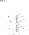
Fig. 2 is a cross-sectional view of section α-α ofFig. 1 . -
Fig. 3 is a perspective view of the reverse input cutoff clutch of this example. -
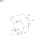
Fig. 4 is a perspective view illustrating a portion of an output member taken out from the reverse input cutoff clutch of this example. -
Fig. 5 is a perspective view illustrating a portion of the output member taken out from the reverse input cutoff clutch of this example. -
Fig. 6 is a view illustrating a state of the reverse input cutoff clutch of this example in which a rotational torque is input to an input member. -
Fig. 7 is an enlarged view of a portion ofFig. 6 . -
Fig. 8(A) is a view illustrating a state of the reverse input cutoff clutch of this example before an output-side engaging portion and an output-side engaged portion are engaged, andFig. 8(B) is a view illustrating a state of the reverse input cutoff clutch of this example after the output-side engaging portion and the output-side engaged portion are engaged. -
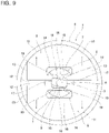
Fig. 9 is a view illustrating a state of the reverse input cutoff clutch of this example in which a rotational torque is reversely input to the output member. -
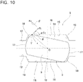
Fig. 10 is an enlarged view of a portion ofFig. 9 illustrating the relationship of a force acting on the engaging element from the output member when a rotational torque is reversely input to the output member. -
Fig. 11 is a view of the reverse input cutoff clutch of this example illustrated in order to explain conditions for the output member to be locked or half-locked when a rotational torque is reversely input to the output member. -
Fig. 1 to Fig. 11 illustrate a reverseinput cutoff clutch 1 of an example of an embodiment of the present invention. In the following description, the axial direction, the radial direction, and the circumferential direction, unless specified otherwise, mean the axial direction, the radial direction, and the circumferential direction of the reverseinput cutoff clutch 1. The axial direction, the radial direction, and the circumferential direction of the reverseinput cutoff clutch 1 coincide with the axial direction, the radial direction, and the circumferential direction of theinput member 2, and coincide with the axial direction, the radial direction, and the circumferential direction of theoutput member 3, and coincide with the axial direction, the radial direction, and the circumferential direction of the pressedmember 4. - The reverse
input cutoff clutch 1 of this example is a lock type reverse input cutoff clutch, and includes aninput member 2, anoutput member 3, a pressedmember 4, and a pair ofengaging elements 5. The reverseinput cutoff clutch 1 has a reverse input cutoff function which transmits rotational torque input to theinput member 2 to theoutput member 3 while completely blocking rotational torque that is reversely input to theoutput member 3 so as not to transmit the rotational torque to theinput member 2, or only a part of it is transmitted to theinput member 2 and the rest is completely blocked. - The
input member 2 is connected to an input-side mechanism such as an electric motor, and rotational torque is input. As illustrated inFigs. 2 and4 , theinput member 2 has aninput shaft portion 6 and a pair of input-side engaging portions 7. Theinput shaft portion 6 has a stepped cylindrical shape. The base end section of the input shaft portion 6 (right end portion inFig. 2 ) is connected to the output portion of the input-side mechanism so as to be able to transmit torque. The pair of input-side engaging portions 7 has an approximately elliptical pillar shape, and it is composed of convex portions extending in the axial direction from two positions on the opposite side in the radial direction of the tip-end surface of the input shaft portion 6 (left end surface inFig. 2 ). The pair of input-side engaging portions 7 are separated from each other in the radial direction. As such, the pair of input-side engaging portions 7 are respectively arranged in portions on the tip-end surface of theinput shaft portion 6 that are deviated radially outward from the center of rotation. The radially outer surfaces of the input-side engaging portions 7 have the same cylindrical contour as the outer circumferential surface of the tip-end portion of theinput shaft portion 6. The radially inward surfaces of the input-side engaging portions 7 are formed by arc-shaped convex surfaces whose center sections in the circumferential direction protrude inward in the radial direction. - The
output member 3 is connected to an output-side mechanism such as a speed reducer, and outputs rotational torque. Theoutput member 3 is arranged coaxially with theinput member 2, and as illustrated inFigs. 2 and5 , has anoutput shaft portion 8 and an output-sideengaging portion 9. Theoutput shaft portion 8 has a cylindrical shape. The base end section of the output shaft portion 8 (left end portion inFig. 2 ) is connected to the input section of the output-side mechanism so as to be able to transmit torque. The output-sideengaging portion 9 has an approximately elliptic cylindrical shape and extends from the center section of the tip-end surface of the output shaft portion 8 (right-end surface inFig. 2 ) in the axial direction. The outer circumferential surface of the output-side engaging portion 9 hasside surfaces 16 on both sides in the minor axis direction (vertical direction ofFigs. 1 ,6 ,8(A), and 8(B) ) and a pair ofguide surfaces 17 that are side surfaces on both sides in the major axis direction (left-right direction ofFigs. 1 ,6 ,8(A), and 8(B) ). - Both side surfaces 16 are formed of flat surfaces orthogonal to the minor axis direction of the output-
side engaging portion 9. Each of the pair of guide surfaces 17 is formed by a convex curved surface. Specifically, each of the pair of guide surfaces 17 is formed by a partially cylindrical convex surface centered on the center axis of the output-side engaging portion 9 (center axis of the output member 3). Further, each of the pair of guide surfaces 17 exists in the same cylindrical surface as the outer circumferential surface of theoutput shaft portion 8. Therefore, regarding theoutput member 3, the outer circumferential surface of the round bar material can be used as the outer circumferential surface of theoutput shaft portion 8 and the pair of guide surfaces 17 so as to be able to reduce the processing cost. However, in a case of implementing the present invention, the convex curved surfaces, which are the pair of guide surfaces, may be partially cylindrical convex surfaces having a radius of curvature smaller than the outer circumferential surface of the output shaft portion, or non-cylindrical convex surfaces such as partially elliptical tubular convex surfaces. - In the
output member 3 of this example, theoutput shaft portion 8 and the output-side engaging portion 9 are integrated, however, in a case of implementing the present invention, the output shaft portion and the output-side engaging portion which are manufactured separately from each other may be connected and fixed to each other to form theoutput member 3. - The output-
side engaging portion 9 is arranged more radially inside than the pair of input-side engaging portions 7, more specifically, it is arranged between the pair of input-side engaging portions 7. - As illustrated in
Figs. 2 ad 3, the pressedmember 4 has a thin annular shape and is fixed to another member (not shown) such as a housing, and its rotation is restricted. The pressedmember 4 has a pressedsurface 10 on its inner circumferential surface. The pressedsurface 10 is formed by a cylindrical concave surface. The pressedsurface 10 is arranged coaxially with theinput member 2 and theoutput member 3 and radially outside theinput member 2 and theoutput member 3. In other words, the pair of input-side engaging portions 7 and the output-side engaging portion 9 are arranged radially inside the pressedsurface 10. - The pair of
engaging elements 5 are arranged radially inside the pressedsurface 10. Each of theengaging elements 5 has an approximately semicircular plate shape. The radially outer surface of theengaging element 5 is formed of a cylindrical convex surface, and forms thepressing surface 11 that is pressed against the pressedsurface 10. Of the radially inward surface of theengaging element 5, a portion other than the portion on which the output-side engagedportions 15 described later is formed forms aflat bottom surface 12. Both side surfaces in the width direction of theengaging element 5 are formed by flat side surfaces 13 perpendicular to thebottom surface 12. The radius of curvature of thepressing surface 11 is equal to or less than the radius of curvature of the pressedsurface 10. - The radial direction with respect to each
engaging element 5 means a direction that is perpendicular to thebottom surface 12 and that is indicated by the arrow A inFig. 1 . Further, the width direction with respect to eachengaging element 5 means a direction that is parallel to thebottom surface 12 and that is indicated by the arrow B. In this example, the radial direction with respect to eachengaging element 5 corresponds to the first direction as a direction away from or toward the pressedsurface 10. The width direction of eachengaging element 5 corresponds to the second direction orthogonal to both the first direction and the axial direction of the pressedsurface 10. - In this example, the
pressing surfaces 11 of the pair ofengaging elements 5 are directed to opposite sides from each other with respect to the radial direction of the pressedsurface 10, and the bottom surfaces 12 of theengaging elements 5 are facing each other in the radial direction. Further, in a state where the pair ofengaging elements 5 are arranged radially inside the pressedsurface 10, the inner diameter of the pressedsurface 10 and the radial dimension of eachengaging element 5 are regulated so that a gap exists at least one of a portion between the pressedsurface 10 and thepressing surfaces 11 and a portion between the bottom surfaces 12. - Each engaging
element 5 has an input-side engagedportion 14 and an output-side engagedportions 15. In this example, the input-side engagedportion 14 is composed of a through hole which penetrates the middle section in the radial direction of theengaging element 5, the through hole being formed by a rectangular hole which is long in the width direction. The input-side engagedportion 14 has a size that allows the input-side engaging portion 7 to be loosely inserted. More specifically, in a state where the input-side engaging portion 7 is inserted inside the input-side engagedportion 14, a gap in the radial direction of theengaging element 5 and a gap in the width direction of theengaging element 5 exist between the input-side engaging portion 7 and the inner surface of the input-side engagedportion 14. Therefore, the input-side engaging portion 7 can be displaced with respect to the input-side engaged portion 14 (engaging element 5) in the direction of rotation, and the input-side engaged portion 14 (engaging element 5) can be displaced with respect to the input-side engaging portion 7 in the radial direction of theengaging element 5. - The output-side engaged
portion 15 is composed of a recessed portion having an approximately rectangular shape that is recessed toward outside in the radial direction from the middle section in the width direction of the bottom surface 12 (radially inside surface on the side far from the pressed surface 10) of eachengaging element 5 of the pair ofengaging elements 5. As illustrated inFigs. 1 ,6 ,8(A), and 8(B) , for example, the output-side engagedportion 15 has a size capable of arranging the half-tip portion of the output-side engaging portion 9 in the minor axis direction inside the output-side engagedportion 15. - The inner surface of the output-side engaged
portion 15 is composed of abottom surface 18 and a pair of guidedsurfaces 19 located at end portions on both sides in the width direction of theengaging element 5 and facing each other in the width direction. Thebottom surface 18 is configured by a flat surface orthogonal to the radial direction of theengaging element 5. The pair of guidedsurfaces 19 is configured by a pair of concave curved surfaces that are inclined in the direction in which the distance between the guided surfaces 19 increases as going toward the radially inside of theengaging element 5, that is, as going toward the direction away from the pressedsurface 10 in the radial direction of theengaging element 5. More specifically, the pair of guidedsurfaces 19 is configured by a pair of concave curved surfaces that can come into contact with the pair of guide surfaces 17 of the output-side engaging portion 9. Each of the guided surfaces 19 is configured by a partially cylindrical concave surface having a radius of curvature equal to that of the guide surfaces 17 or a radius of curvature slightly larger than that of the guide surfaces 17. - In this example, as illustrated in
Figs. 6 and8(B) , the output-side engagedportion 15 has an inner surface shape that matches the outer circumferential surface of the half-tip portion in the minor axis direction of the output-side engaging portion 9. That is, thebottom surface 18 of the output-side engagedportions 15 can be brought into surface contact with theside surface 16 of the output-side engaging portion 9, and the pair of guidedsurfaces 19 of the output-side engagedportion 15 can be brought into surface contact with the half-tip portions in the minor axis direction of the pair of guide surfaces 17 of the output-side engaging portion 9. In a case of implementing the present invention, the guided surfaces may be configured by non-cylindrical concave surfaces such as partially elliptical cylindrical concave surfaces. - In the reverse
input cutoff clutch 1 of this example, in the assembled state, the pair of input-side engaging portions 7 of theinput member 2 arranged on the one side in the axial direction (right side inFig. 2 ) are inserted into the input-side engagedportions 14 of the pair ofengaging elements 5 in the axial direction, and the output-side engaging portion 9 of theoutput member 3 arranged on the other side in the axial direction (left side inFig. 2 ) is inserted between the pair of output-side engagedportions 15 in the axial direction. That is, the pair ofengaging elements 5 are arranged so that the output-side engagedportions 15 sandwich the output-side engaging portion 9 from the outside in the radial direction. Further, in this example, the dimension in the axial direction of the input-side engaging portions 7, the dimension in the axial direction of the output-side engaging portion 9, the dimension in the axial direction of the pressedmember 4, and the dimension in the axial direction of theengaging elements 5 are set to be approximately the same. - The operation of the reverse
input cutoff clutch 1 of this example will be described. - The case where rotational torque is input to the
input member 2 from the input-side mechanism will be described. As illustrated inFig. 6 , when rotational toque is input to theinput member 2, the input-side engaging portions 7 rotate in the direction of rotation of the input member 2 (clockwise in the example ofFig. 6 ) inside the input-side engagedportions 14. Then, the radially inward surfaces of the input-side engaging portions 7 press the inner surfaces of the input-side engagedportions 14 toward inward in the radial direction and move the pair ofengaging elements 5 in a direction away from the pressedsurface 10. That is, the pair ofengaging elements 5 moves inward in the radial direction, which is a direction approaching each other, based on the engagement between the input-side engaging portions 7 and the input-side engagedportions 14. Due to this, the output-side engagedportions 15 of the pair ofengaging elements 5 hold the output-side engaging portion 9 of theoutput member 3 from both sides in the radial direction, and the output-side engaging portion 9 and the pair of output-side engagedportions 15 engage without looseness. As a result, the rotational torque input to theinput member 2 is transmitted to theoutput member 3 through the pair ofengaging elements 5, and is output from theoutput member 3. - Especially, in the structure of this example, when each
engaging element 5 of the pair ofengaging elements 5 moves in the direction away from the pressed surface 10 (inward in the radial direction) as described above, as illustrated inFigs. 1 ,6 ,8(A), and 8(B) , due to the pair of guidedsurfaces 19 located on both sides in the width direction of the output-side engagedportion 15 are guided by the pair of guide surfaces 17 located on both sides in the major axis direction of the half-tip portion in the minor axis direction of the output-side engaging portion 9, the engagingelement 5 is restricted from moving in the width direction. - That is, as illustrated in
Fig. 7 , when the input-side engaging portion 7 comes into contact with the input-side engagedportion 14 by rotational torque being input to theinput member 2, a translational load Fx based on the rotational torque T acts on the contact portion X between the input-side engaging portions 7 and the input-side engaged portions 14 (T = Fx • Rx; Rx is a distance from the center of rotation O of theinput member 2 to the contact portion X). This translational load Fx includes not only a component that presses theengaging element 5 inward in the radial direction - (downward in
Fig. 7 ) but also a component that presses theengaging element 5 in the width direction (rightward inFig. 7 ). Therefore, the engagingelement 5 tends to move not only radially inward (downward inFig. 7 ) but also in the width direction (rightward inFig. 7 ) by the translational load Fx. - In the structure of this example, the engaging
element 5 is restricted from moving in the width direction by guiding the pair of guidedsurfaces 19 of the output-side engagedportion 15 by the pair of guide surfaces 17 of the output-side engaging portion 9. Especially, as illustrated inFigs. 6 and8(B) , in a state where thebottom surface 18 of the output-side engagedportion 15 comes into surface contact with theside surface 16 of the output-side engaging portion 9 and the pair of guidedsurfaces 19 of the output-side engagedportion 15 come into surface contact with the pair of guide surfaces 17 of the output-side engaging portion 9, theengaging elements 5 are completely blocked from moving in the width direction. Therefore, in the structure of this example, when inputting rotational torque to theinput member 2, the engagingelement 5 is effectively prevented from shifting in the width direction and coming into contact with the pressedsurface 10. - In the structure of this example, the pair of guided
surfaces 19 of the output-side engagedportion 15 are configured by a pair of concave curved surfaces that is inclined in a direction in which the distance between each other increases as going toward the radially inside, and the pair of guide surfaces 17 of the output-side engaging portion 9 is configured by a pair of convex curved surfaces that match the pair of guided surfaces 19. Therefore, as illustrated inFig. 8(A) , in a state where theengaging element 5 is separated toward outside in the radial direction from the output-side engaging portion 9, a gap is formed between the pair of guidedsurfaces 19 and the pair of guide surfaces 17, and the size of the gap (dimension in the width direction) becomes larger toward outside in the radial direction (upper side inFig. 8(A) ). Accordingly, in the structure of this example, in a state where theengaging element 5 is separated toward outside in the radial direction from the output-side engaging portion 9, it is possible to moderately allow the movement of theengaging element 5 in the width direction and the direction of rotation, and it is possible to effectively prevent an excessive force from being applied to theengaging element 5. - The case where rotational torque is reversely input to the
output member 3 from the output-side mechanism will be described. When rotational torque is reversely input to theoutput member 3, as illustrated inFig. 9 , the output-side engaging portion 9 rotates in the direction of rotation of the output member 3 (clockwise in the example ofFig. 9 ) inside the pair of output-side engagedportions 15. Then, corner portions that are connecting portions between the side surfaces 16 and the guide surfaces 17 of the output-side engaging portions 9 press the bottom surfaces 18 of the output-side engagedportions 15 toward outward in the radial direction so as to move the pair ofengaging elements 5 in a direction approaching the pressedsurface 10. That is, the pair ofengaging elements 5 move outward in the radial direction, which is a direction away from each other, based on the engagement between the output-side engaging portion 9 and the output-side engagedportions 15. Due to this, thepressing surfaces 11 of the pair ofengaging elements 5 are pressed against the pressedsurface 10 of the pressedmember 4. At this time, thepressing surfaces 11 and the pressedsurface 10 come into contact with each other in the entire range or part (for example, center sections) in the circumferential direction of the pressing surfaces 11. As a result, the rotational torque that is reversely input to theoutput member 3 is transmitted to the pressedmember 4 fixed to another member (not shown) so that the rotational torque is completely blocked and is not transmitted to theinput member 2, or only a part of the rotational torque that is reversely input to theoutput member 3 is transmitted to theinput member 2 and the rest is cut off. - In order to completely block the rotational torque reversely input to the
output member 3 and prevent it from being transmitted to theinput member 2, the pair ofengaging elements 5 are stretched between the output-side engaging portion 9 and the pressedmember 4 so that thepressing surfaces 11 do not slide (relatively rotate) with respect to the pressedsurface 10 so as to lock theoutput member 3. On the other hand, in order to transmit only a part of the rotational torque reversely input to theoutput member 3 is transmitted to theinput member 2 and block the rest, the pair ofengaging elements 5 are stretched between the output-side engaging portion 9 and the pressedmember 4 so that thepressing surfaces 11 slide with respect to the pressedsurface 10 so as to half-lock theoutput member 3. When rotational torque is further reversely input to theoutput member 3 in a state where theoutput member 3 is half-locked, the pair ofengaging elements 5 slide thepressing surfaces 11 with respect to the pressedsurface 10 based on the engagement between the output-side engaging portion 9 and the output-side engagedportions 15, and rotate around the center of rotation of theoutput member 3. When the pair ofengaging elements 5 rotate, the inner surfaces of the input-side engagedportions 14 press the radially inward surfaces of the input-side engaging portions 7 in the circumferential direction (direction of rotation), and part of the rotational torque is transmitted to theinput member 2. - The principle and conditions for locking or half-locking the
output member 3 when rotational torque is reversely input to theoutput member 3 as described above will be more specifically described with reference toFigs. 10 and11 . - When the corner portion of the output-
side engaging portion 9 comes into contact with the bottom surface of the output-side engagedportion 15 as a result of rotational torque being reversely input to theoutput member 3, as illustrated inFig. 10 , a normal force Fc acts on the contact portion Y between the corner portion of the output-side engaging portion 9 and thebottom surface 18 of the output-side engagedportion 15 in the direction perpendicular to thebottom surface 18 of the output-side engagedportion 15. Further, assuming that the friction coefficient between the output-side engaging portion 9 and the output-side engagedportion 15 is µ, the friction force µFc acts on the contact portion Y in the direction parallel to thebottom surface 18 of the output-side engagedportion 15. When the wedge angle between the direction of the line of action of the tangential force Ft acting on the contact portion Y and thebottom surface 18 of the output-side engagedportion 15 is θ, the tangential force Ft is expressed by the following equation (1).
- Therefore, the normal force Fc is expressed by the following equation (2) using the tangential force Ft.

- The magnitude of the torque T transmitted to the
engaging elements 5 from theoutput member 3 when the corner portion of the output-side engaging portion 9 comes into contact with thebottom surface 18 of the output-side engagedportion 15 is expressed by the following equation (3) when the distance from the center of rotation O of theoutput member 3 to the contact portion Y is r.
- As described above, since the normal force Fc acts on the contact portion Y, as illustrated in
Fig. 11 , thepressing surface 11 of theengaging element 5 is pressed to the pressedsurface 10 of the pressedmember 4 by the force of the normal force Fc. Therefore, when the friction coefficient between thepressing surface 11 and the pressedsurface 10 is µ' and the distance from the center of rotation O of theoutput member 3 to the contact portion Z between thepressing surface 11 and the pressedsurface 10 is R, the magnitude of the brake torque T' that acts on theengaging elements 5 is expressed by the following equation (4).
- Accordingly, it can be seen that the friction coefficient µ', the distance R, and the normal force Fc should be increased in order to obtain a larger braking force.
- In order to prevent the rotational torque that is input to the
output member 3 from being transmitted to theinput member 2 by locking theoutput member 3, the transmission torque T and the brake torque T' are required to meet the relationship of the following equation (5).
- Substituting the above equations (1) to (4) into the above equation (5) gives the following equation (6).

- From the above equation (6), it can be seen that if the friction coefficient µ' between the
pressing surface 11 and the pressedsurface 10 is increased, theoutput member 3 can be locked even if the distance R is decreased. - Assuming that the friction coefficient µ and the friction coefficient µ' are both 0.1, the following equation (7) is obtained from the above equation (6).

- From the above equation (7), it can be seen that the
output member 3 can be locked by appropriately setting the distance r from the center of rotation O of theoutput member 3 to the contact portion Y, the distance R from the center of rotation O of theoutput member 3 to the contact portion Z, and the wedge angle θ between the direction of the line of action of the tangential force Ft and thebottom surface 18 of the output-side engagedportion 15. - On the other hand, in order to allow only a part of the rotational torque reversely input to the
output member 3 is transmitted to theinput member 2 and the rest is blocked by half-locking theoutput member 3, the transmission torque T and the brake torque T' are required to meet the relationship of the following equation (8).
- As apparent from the above equation (6), the
output member 3 can be half-locked by appropriately setting the friction coefficient µ between the output-side engaging portion 9 and the output-side engagedportion 15, the friction coefficient µ' between thepressing surface 11 and the pressedsurface 10, the distance r from the center of rotation O to the contact portion Y, the distance R from the center of rotation O to the contact portion Z, and the wedge angle θ between the direction of the line of action of the tangential force Ft and thebottom surface 18 of the output-side engagedportion 15. - In the case where rotational torque is input to the
input member 2 when theoutput member 3 is locked or half-locked, when the normal force acting on theengaging elements 5 from theinput member 2 becomes larger than the normal force Fc acting on theengaging elements 5 from theoutput member 3, theoutput member 3 is released from being locked or semi-locked. That is, the pair ofengaging elements 5 move inward in the radial direction and rotational torque is transmitted from theinput member 2 to theoutput member 3. - With the reverse
input cutoff clutch 1 of this example, the state in which the rotation of theoutput member 3 is prevented or suppressed, that is, the locked or half-locked state as illustrated inFig. 9 can be released easily. - That is, in the reverse
input cutoff clutch 1 of this example, since the force acting on theengaging elements 5 from theinput member 2 and the force acting on theengaging elements 5 from theoutput member 3 are reversed in the radial direction, it is possible to control the moving direction of theengaging elements 5 by regulating the magnitude relationship between both forces. Therefore, the switching operation between the locked or half-locked state as illustrated inFig. 9 and the unlocked state as illustrated inFig. 6 can be stably performed. Accordingly, unlike the conventional reverse input cutoff clutch described inJP 2007-232095A - In the structure of this example, each
engaging element 5 is effectively prevented from contacting the pressedsurface 10 in the width direction since eachengaging element 5 of the pair ofengaging elements 5 is restricted from moving in the width direction due to the pair of guidedsurfaces 19 of the output-side engagedportion 15 being guided by the pair of guide surfaces 17 of the output-side engaging portion 9 when rotational torque is input to theinput member 2 and the pair ofengaging elements 5 move in a direction away from the pressed surface 10 (inward in the radial direction). Therefore, switching between the locked or half-locked state and the unlocked state can be performed more stably when rotational torque being input to theinput member 2. - The reverse
input cutoff clutch 1 of this example includes a pair of input-side engaging portions 7 and a pair ofengaging elements 5. That is, the number of the engaging elements is two. However, in a case of implementing the present invention, the number of the input-side engaging portion and the engaging element is not limited to two, and may be one each or more than three respectively. - Although it is different from the structure of this example, it may be possible to employ a structure in which a dedicated guide member (separate from the output-side engaging portion) is provided between the pair of engaging elements, and when the engaging elements move inward in the radial direction, the engaging elements are restricted from moving in the width direction by the guide member. However, in a case of employing such a structure, as the guide member is used, the number of parts increases and the cost may increase. On the other hand, in the structure of this example, since the movement of the pair of
engaging elements 5 toward inward in the radial direction can be guided by using the output-side engaging portion 9, the number of parts can be reduced as compared with the structure using the guide member. - Although it is different from the structure of this example, it may be also possible to employ a structure in which a guide mechanism is configured by engaging a guide portion on one side such as a concave portion formed on one engaging element of the pair of engaging elements with another guide portion on the other side such as a convex portion formed on the other engaging element of the pair of engaging elements, and the engaging elements are restricted from moving in the width direction by the guide mechanism. However, in a case of employing such a structure, there is a possibility that the management cost of the parts may increase since it is required to prepare two types of engaging elements having different shapes as a pair of engaging elements. On the other hand, in the structure of this example, since the movement of the pair of
engaging elements 5 toward inward in the radial direction can be performed by using the output-side engaging portion 9, it is possible to use members having the same shape as the pair ofengaging elements 5. Therefore, the management cost of the parts can be suppressed. - In a case of implementing the reverse input cutoff clutch of the present invention, it is also possible to employ a structure in which a pair of pressing surfaces which are pressed against the pressed surface are arranged at two locations separated in the circumferential direction of the radially outer surface of each engaging element of the pair of engaging elements, and a portion located between the pair of pressing surfaces in the circumferential direction of the radially outer surface of each engaging element is a non-contact surface that does not come into contact with the pressed surface. If such a structure is adopted, the frictional engagement force between the pressed surface and the pressing surfaces can be increased due to the wedge effect when rotational torque is reversely input to the output member.
- In a case of implementing the reverse input cutoff clutch of the present invention, it is also possible to incorporate a spring that elastically biases the pair of engaging elements in a direction that brings the pair of engaging elements closer to the pressed surface. If such a structure is adopted, in a neutral state where no torque is applied to either the input member or the output member, the pressing surfaces of the engaging elements can be kept in contact with the pressed surface. As a result, when rotational torque is reversely input to the output member, the locked state can be achieved immediately.
-
- 1
- Reverse input cutoff clutch
- 2
- Input member
- 3
- Output member
- 4
- Pressed member
- 5
- Engaging element
- 6
- Input shaft portion
- 7
- Input-side engaging portion
- 8
- Output shaft portion
- 9
- Output-side engaging portion
- 10
- Pressed surface
- 11
- Pressing surface
- 12
- Bottom surface
- 13
- Side surface
- 14
- Input-side engaged portion
- 15
- Output-side engaged portion
- 16
- Side surface
- 17
- Guide surface
- 18
- Bottom surface
- 19
- Guided surface
Claims (3)
- A reverse input cutoff clutch comprising:a pressed member having a pressed surface on an inner circumferential surface thereof,an input member having at least one input-side engaging portion arranged radially inside the pressed surface, the input member being arranged coaxially with the pressed surface,an output member having an output-side engaging portion arranged radially inside the pressed surface and more radially inside than the input-side engaging portion, the output member being arranged coaxially with the pressed surface, andat least one engaging element arranged radially inside the pressed surface so as to move in a first direction as a direction away from or toward the pressed surface, and having at least one pressing surface facing the pressed surface, an input-side engaged portion that engages with the input-side engaging portion, and an output-side engaged portion that engages with the output-side engaging portion,the engaging element displacing so as to move away from the pressed surface based on engagement between the input-side engaging portion and the input-side engaged portion when rotational torque is input to the input member, and transmitting rotational torque input to the input member to the output member by engaging the output-side engaged portions with the output-side engaging portion, and when rotational torque is reversely input to the output member, based on engagement between the output-side engaging portion and the output-side engaging portion, the engaging element frictionally engaging the pressing surface with the pressed surface by pressing the pressing surface against the pressed surface,the output-side engaged portion being composed of a recessed portion provided on a side surface on a side far from the pressed surface in the first direction of the engaging element,the recessed portion having an interior surface comprising a pair of guided surfaces provided on both side portions in a second direction orthogonal to both the first direction and an axial direction of the pressed surface and facing each other in the second direction,the output-side engaging portion having a pair of guide surfaces at two locations facing the pair of guided surfaces, andthe engaging elements being restricted from moving in the second direction due to the pair of guided surfaces being guided by the pair of guide surfaces when the engaging element displaces in a direction away from the pressed surface with regard to the first direction due to rotational torque being input to the input member.
- The reverse input cutoff clutch according to claim 1, wherein the pair of guided surfaces are configured by a pair of concave curved surfaces that are inclined in a direction in which a distance between each other increases in the direction away from the pressed surface with regard to the first direction, and the pair of guide surfaces are configured by a pair of convex curved surfaces that is able to contact the pair of concave curved surfaces.
- The reverse input cutoff clutch according to claim 1 or 2, wherein a pair of the input-side engaging portions and a pair of the engaging elements are provided so as to sandwich the output-side engaging portion from both sides in the radial direction.
Applications Claiming Priority (2)
| Application Number | Priority Date | Filing Date | Title |
|---|---|---|---|
| JP2020012185 | 2020-01-29 | ||
| PCT/JP2020/043776 WO2021152980A1 (en) | 2020-01-29 | 2020-11-25 | Reverse-input-blocking clutch |
Publications (3)
| Publication Number | Publication Date |
|---|---|
| EP3981997A1 true EP3981997A1 (en) | 2022-04-13 |
| EP3981997A4 EP3981997A4 (en) | 2022-08-10 |
| EP3981997B1 EP3981997B1 (en) | 2023-06-28 |
Family
ID=77078924
Family Applications (1)
| Application Number | Title | Priority Date | Filing Date |
|---|---|---|---|
| EP20917248.5A Active EP3981997B1 (en) | 2020-01-29 | 2020-11-25 | Reverse input cutoff clutch |
Country Status (5)
| Country | Link |
|---|---|
| US (1) | US11506249B2 (en) |
| EP (1) | EP3981997B1 (en) |
| JP (1) | JP6962510B1 (en) |
| CN (1) | CN113906230A (en) |
| WO (1) | WO2021152980A1 (en) |
Families Citing this family (4)
| Publication number | Priority date | Publication date | Assignee | Title |
|---|---|---|---|---|
| WO2022163617A1 (en) * | 2021-01-28 | 2022-08-04 | 日本精工株式会社 | Electric motor with reverse-input-blocking clutch |
| EP4239210B1 (en) | 2021-11-15 | 2024-11-13 | NSK Ltd. | Reverse-input-blocking clutch |
| KR20230134666A (en) * | 2022-03-15 | 2023-09-22 | 현대자동차주식회사 | Clutch for Preventing Back Drive |
| WO2025056118A1 (en) * | 2023-09-13 | 2025-03-20 | Schaeffler Technologies AG & Co. KG | Linear drive with braking mechanism |
Family Cites Families (19)
| Publication number | Priority date | Publication date | Assignee | Title |
|---|---|---|---|---|
| US1617745A (en) * | 1927-02-15 | Albert cotysinard | ||
| US1575038A (en) * | 1924-11-07 | 1926-03-02 | Clas Angelo Robert | Window regulator |
| US2031186A (en) * | 1935-07-12 | 1936-02-18 | Andrew L Still | Automatic brake |
| US3051282A (en) * | 1959-12-15 | 1962-08-28 | Whitney E Greene | Self-locking rotary transmission |
| US3024884A (en) * | 1959-12-17 | 1962-03-13 | Adams Rite Mfg Company | Back locking drive means |
| DE3911075A1 (en) * | 1989-04-06 | 1990-10-11 | Schaeffler Waelzlager Kg | LOW-SWITCH FREE CLUTCH |
| US5007511A (en) * | 1989-11-02 | 1991-04-16 | Dana Corporation | Bi-directional back stopping clutch |
| DE19926994C2 (en) * | 1999-06-08 | 2001-09-20 | Brose Fahrzeugteile | Adjustment device |
| KR100442747B1 (en) * | 2002-03-14 | 2004-08-02 | 주식회사다스 | Pumping device of seat for vehicle |
| US7163097B2 (en) * | 2004-02-26 | 2007-01-16 | Siemens Vdo Automotive Corporation | Bi-directional friction clutch assembly for electric motors to prevent backdrive |
| US7353930B2 (en) * | 2005-02-10 | 2008-04-08 | Continental Automotive Systems Us, Inc. | Bi-directional friction clutch or brake assembly for transmissions |
| JP4965871B2 (en) | 2006-03-01 | 2012-07-04 | Ntn株式会社 | Reverse input prevention clutch |
| JP5297993B2 (en) * | 2009-06-23 | 2013-09-25 | アスモ株式会社 | Clutch and motor |
| JP6583075B2 (en) * | 2016-03-17 | 2019-10-02 | 株式会社デンソー | Clutch, motor and power window device |
| WO2019026794A1 (en) | 2017-08-01 | 2019-02-07 | 日本精工株式会社 | Reverse input shutoff clutch, electric valve timing adjustment device, variable compression ratio device, and electric power steering device |
| JP7139617B2 (en) * | 2018-02-14 | 2022-09-21 | 日本精工株式会社 | reverse input cutoff clutch |
| JP7052529B2 (en) * | 2018-04-24 | 2022-04-12 | 日本精工株式会社 | Actuator and steer-by-wire steering system |
| WO2019216280A1 (en) * | 2018-05-07 | 2019-11-14 | 日本精工株式会社 | Reverse input blocking clutch and actuator |
| JP7135470B2 (en) * | 2018-06-11 | 2022-09-13 | 日本精工株式会社 | steering device |
-
2020
- 2020-11-25 CN CN202080040380.5A patent/CN113906230A/en not_active Withdrawn
- 2020-11-25 JP JP2021542351A patent/JP6962510B1/en active Active
- 2020-11-25 WO PCT/JP2020/043776 patent/WO2021152980A1/en not_active Ceased
- 2020-11-25 US US17/596,524 patent/US11506249B2/en active Active
- 2020-11-25 EP EP20917248.5A patent/EP3981997B1/en active Active
Also Published As
| Publication number | Publication date |
|---|---|
| US20220205495A1 (en) | 2022-06-30 |
| WO2021152980A1 (en) | 2021-08-05 |
| JP6962510B1 (en) | 2021-11-05 |
| EP3981997A4 (en) | 2022-08-10 |
| US11506249B2 (en) | 2022-11-22 |
| JPWO2021152980A1 (en) | 2021-08-05 |
| CN113906230A (en) | 2022-01-07 |
| EP3981997B1 (en) | 2023-06-28 |
Similar Documents
| Publication | Publication Date | Title |
|---|---|---|
| EP3981997B1 (en) | Reverse input cutoff clutch | |
| EP2840275B1 (en) | Clutch unit | |
| CN110945260B (en) | Clutch and power transmission structure of vehicle | |
| JP7060169B2 (en) | Reverse input cutoff clutch | |
| US11486458B2 (en) | Clutch unit | |
| EP4421341A1 (en) | Power transmission device | |
| EP3434924A1 (en) | Clutch unit | |
| JP7139617B2 (en) | reverse input cutoff clutch | |
| EP2264328A1 (en) | Clutch unit | |
| WO2023195203A1 (en) | Reverse-input blocking clutch | |
| JPH11125268A (en) | Synchronizer | |
| JP5905363B2 (en) | Brake device | |
| US11629768B2 (en) | Reverse input cutoff clutch | |
| JP7375986B2 (en) | Reverse input cutoff clutch | |
| US11767913B2 (en) | Rotation locking device | |
| JP7188177B2 (en) | reverse input cutoff clutch | |
| JP2023018310A (en) | Reverse input cutoff clutch and clutch unit comprising the same | |
| WO2023136149A1 (en) | Reverse input cutoff clutch and method for assembling same | |
| JP2017198292A (en) | Gear speed reducer | |
| JP2022147480A (en) | Reverse input cutoff clutch and clutch unit having the same | |
| JP2023022882A (en) | reverse input cutoff clutch | |
| JP2024110195A (en) | Clutch unit | |
| JP2023083777A (en) | One-way joint | |
| CN121488115A (en) | Reverse input cut-off clutch and reverse input cut-off system |
Legal Events
| Date | Code | Title | Description |
|---|---|---|---|
| STAA | Information on the status of an ep patent application or granted ep patent |
Free format text: STATUS: THE INTERNATIONAL PUBLICATION HAS BEEN MADE |
|
| PUAI | Public reference made under article 153(3) epc to a published international application that has entered the european phase |
Free format text: ORIGINAL CODE: 0009012 |
|
| STAA | Information on the status of an ep patent application or granted ep patent |
Free format text: STATUS: REQUEST FOR EXAMINATION WAS MADE |
|
| 17P | Request for examination filed |
Effective date: 20220105 |
|
| AK | Designated contracting states |
Kind code of ref document: A1 Designated state(s): AL AT BE BG CH CY CZ DE DK EE ES FI FR GB GR HR HU IE IS IT LI LT LU LV MC MK MT NL NO PL PT RO RS SE SI SK SM TR |
|
| STAA | Information on the status of an ep patent application or granted ep patent |
Free format text: STATUS: EXAMINATION IS IN PROGRESS |
|
| A4 | Supplementary search report drawn up and despatched |
Effective date: 20220708 |
|
| RIC1 | Information provided on ipc code assigned before grant |
Ipc: F16D 43/02 20060101ALI20220704BHEP Ipc: F16D 125/28 20120101ALI20220704BHEP Ipc: F16D 121/14 20120101ALI20220704BHEP Ipc: F16D 65/22 20060101ALI20220704BHEP Ipc: F16D 67/02 20060101ALI20220704BHEP Ipc: F16D 51/18 20060101AFI20220704BHEP |
|
| 17Q | First examination report despatched |
Effective date: 20220720 |
|
| GRAP | Despatch of communication of intention to grant a patent |
Free format text: ORIGINAL CODE: EPIDOSNIGR1 |
|
| STAA | Information on the status of an ep patent application or granted ep patent |
Free format text: STATUS: GRANT OF PATENT IS INTENDED |
|
| DAV | Request for validation of the european patent (deleted) | ||
| DAX | Request for extension of the european patent (deleted) | ||
| INTG | Intention to grant announced |
Effective date: 20230216 |
|
| GRAS | Grant fee paid |
Free format text: ORIGINAL CODE: EPIDOSNIGR3 |
|
| GRAA | (expected) grant |
Free format text: ORIGINAL CODE: 0009210 |
|
| STAA | Information on the status of an ep patent application or granted ep patent |
Free format text: STATUS: THE PATENT HAS BEEN GRANTED |
|
| AK | Designated contracting states |
Kind code of ref document: B1 Designated state(s): AL AT BE BG CH CY CZ DE DK EE ES FI FR GB GR HR HU IE IS IT LI LT LU LV MC MK MT NL NO PL PT RO RS SE SI SK SM TR |
|
| REG | Reference to a national code |
Ref country code: CH Ref legal event code: EP |
|
| REG | Reference to a national code |
Ref country code: AT Ref legal event code: REF Ref document number: 1582933 Country of ref document: AT Kind code of ref document: T Effective date: 20230715 |
|
| REG | Reference to a national code |
Ref country code: IE Ref legal event code: FG4D |
|
| REG | Reference to a national code |
Ref country code: DE Ref legal event code: R096 Ref document number: 602020013152 Country of ref document: DE |
|
| REG | Reference to a national code |
Ref country code: LT Ref legal event code: MG9D |
|
| PG25 | Lapsed in a contracting state [announced via postgrant information from national office to epo] |
Ref country code: SE Free format text: LAPSE BECAUSE OF FAILURE TO SUBMIT A TRANSLATION OF THE DESCRIPTION OR TO PAY THE FEE WITHIN THE PRESCRIBED TIME-LIMIT Effective date: 20230628 Ref country code: NO Free format text: LAPSE BECAUSE OF FAILURE TO SUBMIT A TRANSLATION OF THE DESCRIPTION OR TO PAY THE FEE WITHIN THE PRESCRIBED TIME-LIMIT Effective date: 20230928 |
|
| REG | Reference to a national code |
Ref country code: NL Ref legal event code: MP Effective date: 20230628 |
|
| REG | Reference to a national code |
Ref country code: AT Ref legal event code: MK05 Ref document number: 1582933 Country of ref document: AT Kind code of ref document: T Effective date: 20230628 |
|
| PG25 | Lapsed in a contracting state [announced via postgrant information from national office to epo] |
Ref country code: RS Free format text: LAPSE BECAUSE OF FAILURE TO SUBMIT A TRANSLATION OF THE DESCRIPTION OR TO PAY THE FEE WITHIN THE PRESCRIBED TIME-LIMIT Effective date: 20230628 Ref country code: NL Free format text: LAPSE BECAUSE OF FAILURE TO SUBMIT A TRANSLATION OF THE DESCRIPTION OR TO PAY THE FEE WITHIN THE PRESCRIBED TIME-LIMIT Effective date: 20230628 Ref country code: LV Free format text: LAPSE BECAUSE OF FAILURE TO SUBMIT A TRANSLATION OF THE DESCRIPTION OR TO PAY THE FEE WITHIN THE PRESCRIBED TIME-LIMIT Effective date: 20230628 Ref country code: LT Free format text: LAPSE BECAUSE OF FAILURE TO SUBMIT A TRANSLATION OF THE DESCRIPTION OR TO PAY THE FEE WITHIN THE PRESCRIBED TIME-LIMIT Effective date: 20230628 Ref country code: HR Free format text: LAPSE BECAUSE OF FAILURE TO SUBMIT A TRANSLATION OF THE DESCRIPTION OR TO PAY THE FEE WITHIN THE PRESCRIBED TIME-LIMIT Effective date: 20230628 Ref country code: GR Free format text: LAPSE BECAUSE OF FAILURE TO SUBMIT A TRANSLATION OF THE DESCRIPTION OR TO PAY THE FEE WITHIN THE PRESCRIBED TIME-LIMIT Effective date: 20230929 |
|
| PG25 | Lapsed in a contracting state [announced via postgrant information from national office to epo] |
Ref country code: FI Free format text: LAPSE BECAUSE OF FAILURE TO SUBMIT A TRANSLATION OF THE DESCRIPTION OR TO PAY THE FEE WITHIN THE PRESCRIBED TIME-LIMIT Effective date: 20230628 |
|
| PG25 | Lapsed in a contracting state [announced via postgrant information from national office to epo] |
Ref country code: SK Free format text: LAPSE BECAUSE OF FAILURE TO SUBMIT A TRANSLATION OF THE DESCRIPTION OR TO PAY THE FEE WITHIN THE PRESCRIBED TIME-LIMIT Effective date: 20230628 |
|
| PG25 | Lapsed in a contracting state [announced via postgrant information from national office to epo] |
Ref country code: ES Free format text: LAPSE BECAUSE OF FAILURE TO SUBMIT A TRANSLATION OF THE DESCRIPTION OR TO PAY THE FEE WITHIN THE PRESCRIBED TIME-LIMIT Effective date: 20230628 |
|
| PG25 | Lapsed in a contracting state [announced via postgrant information from national office to epo] |
Ref country code: IS Free format text: LAPSE BECAUSE OF FAILURE TO SUBMIT A TRANSLATION OF THE DESCRIPTION OR TO PAY THE FEE WITHIN THE PRESCRIBED TIME-LIMIT Effective date: 20231028 |
|
| PG25 | Lapsed in a contracting state [announced via postgrant information from national office to epo] |
Ref country code: SM Free format text: LAPSE BECAUSE OF FAILURE TO SUBMIT A TRANSLATION OF THE DESCRIPTION OR TO PAY THE FEE WITHIN THE PRESCRIBED TIME-LIMIT Effective date: 20230628 Ref country code: SK Free format text: LAPSE BECAUSE OF FAILURE TO SUBMIT A TRANSLATION OF THE DESCRIPTION OR TO PAY THE FEE WITHIN THE PRESCRIBED TIME-LIMIT Effective date: 20230628 Ref country code: RO Free format text: LAPSE BECAUSE OF FAILURE TO SUBMIT A TRANSLATION OF THE DESCRIPTION OR TO PAY THE FEE WITHIN THE PRESCRIBED TIME-LIMIT Effective date: 20230628 Ref country code: PT Free format text: LAPSE BECAUSE OF FAILURE TO SUBMIT A TRANSLATION OF THE DESCRIPTION OR TO PAY THE FEE WITHIN THE PRESCRIBED TIME-LIMIT Effective date: 20231030 Ref country code: IS Free format text: LAPSE BECAUSE OF FAILURE TO SUBMIT A TRANSLATION OF THE DESCRIPTION OR TO PAY THE FEE WITHIN THE PRESCRIBED TIME-LIMIT Effective date: 20231028 Ref country code: ES Free format text: LAPSE BECAUSE OF FAILURE TO SUBMIT A TRANSLATION OF THE DESCRIPTION OR TO PAY THE FEE WITHIN THE PRESCRIBED TIME-LIMIT Effective date: 20230628 Ref country code: EE Free format text: LAPSE BECAUSE OF FAILURE TO SUBMIT A TRANSLATION OF THE DESCRIPTION OR TO PAY THE FEE WITHIN THE PRESCRIBED TIME-LIMIT Effective date: 20230628 Ref country code: CZ Free format text: LAPSE BECAUSE OF FAILURE TO SUBMIT A TRANSLATION OF THE DESCRIPTION OR TO PAY THE FEE WITHIN THE PRESCRIBED TIME-LIMIT Effective date: 20230628 Ref country code: AT Free format text: LAPSE BECAUSE OF FAILURE TO SUBMIT A TRANSLATION OF THE DESCRIPTION OR TO PAY THE FEE WITHIN THE PRESCRIBED TIME-LIMIT Effective date: 20230628 |
|
| PG25 | Lapsed in a contracting state [announced via postgrant information from national office to epo] |
Ref country code: PL Free format text: LAPSE BECAUSE OF FAILURE TO SUBMIT A TRANSLATION OF THE DESCRIPTION OR TO PAY THE FEE WITHIN THE PRESCRIBED TIME-LIMIT Effective date: 20230628 |
|
| REG | Reference to a national code |
Ref country code: DE Ref legal event code: R097 Ref document number: 602020013152 Country of ref document: DE |
|
| PG25 | Lapsed in a contracting state [announced via postgrant information from national office to epo] |
Ref country code: DK Free format text: LAPSE BECAUSE OF FAILURE TO SUBMIT A TRANSLATION OF THE DESCRIPTION OR TO PAY THE FEE WITHIN THE PRESCRIBED TIME-LIMIT Effective date: 20230628 |
|
| PLBE | No opposition filed within time limit |
Free format text: ORIGINAL CODE: 0009261 |
|
| STAA | Information on the status of an ep patent application or granted ep patent |
Free format text: STATUS: NO OPPOSITION FILED WITHIN TIME LIMIT |
|
| PG25 | Lapsed in a contracting state [announced via postgrant information from national office to epo] |
Ref country code: IT Free format text: LAPSE BECAUSE OF FAILURE TO SUBMIT A TRANSLATION OF THE DESCRIPTION OR TO PAY THE FEE WITHIN THE PRESCRIBED TIME-LIMIT Effective date: 20230628 |
|
| 26N | No opposition filed |
Effective date: 20240402 |
|
| REG | Reference to a national code |
Ref country code: CH Ref legal event code: PL |
|
| PG25 | Lapsed in a contracting state [announced via postgrant information from national office to epo] |
Ref country code: MC Free format text: LAPSE BECAUSE OF FAILURE TO SUBMIT A TRANSLATION OF THE DESCRIPTION OR TO PAY THE FEE WITHIN THE PRESCRIBED TIME-LIMIT Effective date: 20230628 |
|
| PG25 | Lapsed in a contracting state [announced via postgrant information from national office to epo] |
Ref country code: LU Free format text: LAPSE BECAUSE OF NON-PAYMENT OF DUE FEES Effective date: 20231125 |
|
| PG25 | Lapsed in a contracting state [announced via postgrant information from national office to epo] |
Ref country code: CH Free format text: LAPSE BECAUSE OF NON-PAYMENT OF DUE FEES Effective date: 20231130 |
|
| PG25 | Lapsed in a contracting state [announced via postgrant information from national office to epo] |
Ref country code: MC Free format text: LAPSE BECAUSE OF FAILURE TO SUBMIT A TRANSLATION OF THE DESCRIPTION OR TO PAY THE FEE WITHIN THE PRESCRIBED TIME-LIMIT Effective date: 20230628 Ref country code: LU Free format text: LAPSE BECAUSE OF NON-PAYMENT OF DUE FEES Effective date: 20231125 Ref country code: CH Free format text: LAPSE BECAUSE OF NON-PAYMENT OF DUE FEES Effective date: 20231130 Ref country code: SI Free format text: LAPSE BECAUSE OF FAILURE TO SUBMIT A TRANSLATION OF THE DESCRIPTION OR TO PAY THE FEE WITHIN THE PRESCRIBED TIME-LIMIT Effective date: 20230628 |
|
| REG | Reference to a national code |
Ref country code: BE Ref legal event code: MM Effective date: 20231130 |
|
| REG | Reference to a national code |
Ref country code: IE Ref legal event code: MM4A |
|
| PG25 | Lapsed in a contracting state [announced via postgrant information from national office to epo] |
Ref country code: IE Free format text: LAPSE BECAUSE OF NON-PAYMENT OF DUE FEES Effective date: 20231125 |
|
| PG25 | Lapsed in a contracting state [announced via postgrant information from national office to epo] |
Ref country code: BE Free format text: LAPSE BECAUSE OF NON-PAYMENT OF DUE FEES Effective date: 20231130 |
|
| PG25 | Lapsed in a contracting state [announced via postgrant information from national office to epo] |
Ref country code: IE Free format text: LAPSE BECAUSE OF NON-PAYMENT OF DUE FEES Effective date: 20231125 Ref country code: BE Free format text: LAPSE BECAUSE OF NON-PAYMENT OF DUE FEES Effective date: 20231130 |
|
| PG25 | Lapsed in a contracting state [announced via postgrant information from national office to epo] |
Ref country code: BG Free format text: LAPSE BECAUSE OF FAILURE TO SUBMIT A TRANSLATION OF THE DESCRIPTION OR TO PAY THE FEE WITHIN THE PRESCRIBED TIME-LIMIT Effective date: 20230628 |
|
| PG25 | Lapsed in a contracting state [announced via postgrant information from national office to epo] |
Ref country code: BG Free format text: LAPSE BECAUSE OF FAILURE TO SUBMIT A TRANSLATION OF THE DESCRIPTION OR TO PAY THE FEE WITHIN THE PRESCRIBED TIME-LIMIT Effective date: 20230628 |
|
| PG25 | Lapsed in a contracting state [announced via postgrant information from national office to epo] |
Ref country code: CY Free format text: LAPSE BECAUSE OF FAILURE TO SUBMIT A TRANSLATION OF THE DESCRIPTION OR TO PAY THE FEE WITHIN THE PRESCRIBED TIME-LIMIT; INVALID AB INITIO Effective date: 20201125 |
|
| PG25 | Lapsed in a contracting state [announced via postgrant information from national office to epo] |
Ref country code: HU Free format text: LAPSE BECAUSE OF FAILURE TO SUBMIT A TRANSLATION OF THE DESCRIPTION OR TO PAY THE FEE WITHIN THE PRESCRIBED TIME-LIMIT; INVALID AB INITIO Effective date: 20201125 |
|
| PGFP | Annual fee paid to national office [announced via postgrant information from national office to epo] |
Ref country code: FR Payment date: 20250930 Year of fee payment: 6 |
|
| PG25 | Lapsed in a contracting state [announced via postgrant information from national office to epo] |
Ref country code: TR Free format text: LAPSE BECAUSE OF FAILURE TO SUBMIT A TRANSLATION OF THE DESCRIPTION OR TO PAY THE FEE WITHIN THE PRESCRIBED TIME-LIMIT Effective date: 20230628 |
|
| PGFP | Annual fee paid to national office [announced via postgrant information from national office to epo] |
Ref country code: DE Payment date: 20250930 Year of fee payment: 6 |
|
| PGFP | Annual fee paid to national office [announced via postgrant information from national office to epo] |
Ref country code: GB Payment date: 20251001 Year of fee payment: 6 |