EP3981972B1 - A heat exchanger - Google Patents
A heat exchanger Download PDFInfo
- Publication number
- EP3981972B1 EP3981972B1 EP21200620.9A EP21200620A EP3981972B1 EP 3981972 B1 EP3981972 B1 EP 3981972B1 EP 21200620 A EP21200620 A EP 21200620A EP 3981972 B1 EP3981972 B1 EP 3981972B1
- Authority
- EP
- European Patent Office
- Prior art keywords
- module
- vane
- flow
- heat exchanger
- fan
- Prior art date
- Legal status (The legal status is an assumption and is not a legal conclusion. Google has not performed a legal analysis and makes no representation as to the accuracy of the status listed.)
- Active
Links
Images


Classifications
-
- F—MECHANICAL ENGINEERING; LIGHTING; HEATING; WEAPONS; BLASTING
- F02—COMBUSTION ENGINES; HOT-GAS OR COMBUSTION-PRODUCT ENGINE PLANTS
- F02C—GAS-TURBINE PLANTS; AIR INTAKES FOR JET-PROPULSION PLANTS; CONTROLLING FUEL SUPPLY IN AIR-BREATHING JET-PROPULSION PLANTS
- F02C7/00—Features, components parts, details or accessories, not provided for in, or of interest apart form groups F02C1/00 - F02C6/00; Air intakes for jet-propulsion plants
- F02C7/04—Air intakes for gas-turbine plants or jet-propulsion plants
-
- F—MECHANICAL ENGINEERING; LIGHTING; HEATING; WEAPONS; BLASTING
- F01—MACHINES OR ENGINES IN GENERAL; ENGINE PLANTS IN GENERAL; STEAM ENGINES
- F01D—NON-POSITIVE DISPLACEMENT MACHINES OR ENGINES, e.g. STEAM TURBINES
- F01D5/00—Blades; Blade-carrying members; Heating, heat-insulating, cooling or antivibration means on the blades or the members
- F01D5/12—Blades
- F01D5/14—Form or construction
- F01D5/18—Hollow blades, i.e. blades with cooling or heating channels or cavities; Heating, heat-insulating or cooling means on blades
-
- F—MECHANICAL ENGINEERING; LIGHTING; HEATING; WEAPONS; BLASTING
- F02—COMBUSTION ENGINES; HOT-GAS OR COMBUSTION-PRODUCT ENGINE PLANTS
- F02C—GAS-TURBINE PLANTS; AIR INTAKES FOR JET-PROPULSION PLANTS; CONTROLLING FUEL SUPPLY IN AIR-BREATHING JET-PROPULSION PLANTS
- F02C7/00—Features, components parts, details or accessories, not provided for in, or of interest apart form groups F02C1/00 - F02C6/00; Air intakes for jet-propulsion plants
- F02C7/04—Air intakes for gas-turbine plants or jet-propulsion plants
- F02C7/047—Heating to prevent icing
-
- F—MECHANICAL ENGINEERING; LIGHTING; HEATING; WEAPONS; BLASTING
- F01—MACHINES OR ENGINES IN GENERAL; ENGINE PLANTS IN GENERAL; STEAM ENGINES
- F01D—NON-POSITIVE DISPLACEMENT MACHINES OR ENGINES, e.g. STEAM TURBINES
- F01D17/00—Regulating or controlling by varying flow
- F01D17/10—Final actuators
- F01D17/12—Final actuators arranged in stator parts
- F01D17/14—Final actuators arranged in stator parts varying effective cross-sectional area of nozzles or guide conduits
-
- F—MECHANICAL ENGINEERING; LIGHTING; HEATING; WEAPONS; BLASTING
- F01—MACHINES OR ENGINES IN GENERAL; ENGINE PLANTS IN GENERAL; STEAM ENGINES
- F01D—NON-POSITIVE DISPLACEMENT MACHINES OR ENGINES, e.g. STEAM TURBINES
- F01D25/00—Component parts, details, or accessories, not provided for in, or of interest apart from, other groups
- F01D25/08—Cooling; Heating; Heat-insulation
- F01D25/12—Cooling
-
- F—MECHANICAL ENGINEERING; LIGHTING; HEATING; WEAPONS; BLASTING
- F01—MACHINES OR ENGINES IN GENERAL; ENGINE PLANTS IN GENERAL; STEAM ENGINES
- F01D—NON-POSITIVE DISPLACEMENT MACHINES OR ENGINES, e.g. STEAM TURBINES
- F01D5/00—Blades; Blade-carrying members; Heating, heat-insulating, cooling or antivibration means on the blades or the members
- F01D5/02—Blade-carrying members, e.g. rotors
- F01D5/021—Blade-carrying members, e.g. rotors for flow machines or engines with only one axial stage
-
- F—MECHANICAL ENGINEERING; LIGHTING; HEATING; WEAPONS; BLASTING
- F01—MACHINES OR ENGINES IN GENERAL; ENGINE PLANTS IN GENERAL; STEAM ENGINES
- F01D—NON-POSITIVE DISPLACEMENT MACHINES OR ENGINES, e.g. STEAM TURBINES
- F01D9/00—Stators
- F01D9/02—Nozzles; Nozzle boxes; Stator blades; Guide conduits, e.g. individual nozzles
- F01D9/04—Nozzles; Nozzle boxes; Stator blades; Guide conduits, e.g. individual nozzles forming ring or sector
- F01D9/041—Nozzles; Nozzle boxes; Stator blades; Guide conduits, e.g. individual nozzles forming ring or sector using blades
-
- F—MECHANICAL ENGINEERING; LIGHTING; HEATING; WEAPONS; BLASTING
- F02—COMBUSTION ENGINES; HOT-GAS OR COMBUSTION-PRODUCT ENGINE PLANTS
- F02C—GAS-TURBINE PLANTS; AIR INTAKES FOR JET-PROPULSION PLANTS; CONTROLLING FUEL SUPPLY IN AIR-BREATHING JET-PROPULSION PLANTS
- F02C7/00—Features, components parts, details or accessories, not provided for in, or of interest apart form groups F02C1/00 - F02C6/00; Air intakes for jet-propulsion plants
- F02C7/08—Heating air supply before combustion, e.g. by exhaust gases
-
- F—MECHANICAL ENGINEERING; LIGHTING; HEATING; WEAPONS; BLASTING
- F02—COMBUSTION ENGINES; HOT-GAS OR COMBUSTION-PRODUCT ENGINE PLANTS
- F02C—GAS-TURBINE PLANTS; AIR INTAKES FOR JET-PROPULSION PLANTS; CONTROLLING FUEL SUPPLY IN AIR-BREATHING JET-PROPULSION PLANTS
- F02C7/00—Features, components parts, details or accessories, not provided for in, or of interest apart form groups F02C1/00 - F02C6/00; Air intakes for jet-propulsion plants
- F02C7/12—Cooling of plants
- F02C7/14—Cooling of plants of fluids in the plant, e.g. lubricant or fuel
-
- F—MECHANICAL ENGINEERING; LIGHTING; HEATING; WEAPONS; BLASTING
- F28—HEAT EXCHANGE IN GENERAL
- F28D—HEAT-EXCHANGE APPARATUS, NOT PROVIDED FOR IN ANOTHER SUBCLASS, IN WHICH THE HEAT-EXCHANGE MEDIA DO NOT COME INTO DIRECT CONTACT
- F28D7/00—Heat-exchange apparatus having stationary tubular conduit assemblies for both heat-exchange media, the media being in contact with different sides of a conduit wall
- F28D7/16—Heat-exchange apparatus having stationary tubular conduit assemblies for both heat-exchange media, the media being in contact with different sides of a conduit wall the conduits being arranged in parallel spaced relation
- F28D7/1615—Heat-exchange apparatus having stationary tubular conduit assemblies for both heat-exchange media, the media being in contact with different sides of a conduit wall the conduits being arranged in parallel spaced relation the conduits being inside a casing and extending at an angle to the longitudinal axis of the casing; the conduits crossing the conduit for the other heat exchange medium
-
- F—MECHANICAL ENGINEERING; LIGHTING; HEATING; WEAPONS; BLASTING
- F05—INDEXING SCHEMES RELATING TO ENGINES OR PUMPS IN VARIOUS SUBCLASSES OF CLASSES F01-F04
- F05D—INDEXING SCHEME FOR ASPECTS RELATING TO NON-POSITIVE-DISPLACEMENT MACHINES OR ENGINES, GAS-TURBINES OR JET-PROPULSION PLANTS
- F05D2220/00—Application
- F05D2220/30—Application in turbines
- F05D2220/32—Application in turbines in gas turbines
-
- F—MECHANICAL ENGINEERING; LIGHTING; HEATING; WEAPONS; BLASTING
- F05—INDEXING SCHEMES RELATING TO ENGINES OR PUMPS IN VARIOUS SUBCLASSES OF CLASSES F01-F04
- F05D—INDEXING SCHEME FOR ASPECTS RELATING TO NON-POSITIVE-DISPLACEMENT MACHINES OR ENGINES, GAS-TURBINES OR JET-PROPULSION PLANTS
- F05D2220/00—Application
- F05D2220/30—Application in turbines
- F05D2220/36—Application in turbines specially adapted for the fan of turbofan engines
-
- F—MECHANICAL ENGINEERING; LIGHTING; HEATING; WEAPONS; BLASTING
- F05—INDEXING SCHEMES RELATING TO ENGINES OR PUMPS IN VARIOUS SUBCLASSES OF CLASSES F01-F04
- F05D—INDEXING SCHEME FOR ASPECTS RELATING TO NON-POSITIVE-DISPLACEMENT MACHINES OR ENGINES, GAS-TURBINES OR JET-PROPULSION PLANTS
- F05D2240/00—Components
- F05D2240/10—Stators
- F05D2240/12—Fluid guiding means, e.g. vanes
-
- F—MECHANICAL ENGINEERING; LIGHTING; HEATING; WEAPONS; BLASTING
- F05—INDEXING SCHEMES RELATING TO ENGINES OR PUMPS IN VARIOUS SUBCLASSES OF CLASSES F01-F04
- F05D—INDEXING SCHEME FOR ASPECTS RELATING TO NON-POSITIVE-DISPLACEMENT MACHINES OR ENGINES, GAS-TURBINES OR JET-PROPULSION PLANTS
- F05D2260/00—Function
- F05D2260/20—Heat transfer, e.g. cooling
- F05D2260/213—Heat transfer, e.g. cooling by the provision of a heat exchanger within the cooling circuit
-
- F—MECHANICAL ENGINEERING; LIGHTING; HEATING; WEAPONS; BLASTING
- F28—HEAT EXCHANGE IN GENERAL
- F28D—HEAT-EXCHANGE APPARATUS, NOT PROVIDED FOR IN ANOTHER SUBCLASS, IN WHICH THE HEAT-EXCHANGE MEDIA DO NOT COME INTO DIRECT CONTACT
- F28D21/00—Heat-exchange apparatus not covered by any of the groups F28D1/00 - F28D20/00
- F28D2021/0019—Other heat exchangers for particular applications; Heat exchange systems not otherwise provided for
- F28D2021/0021—Other heat exchangers for particular applications; Heat exchange systems not otherwise provided for for aircrafts or cosmonautics
-
- F—MECHANICAL ENGINEERING; LIGHTING; HEATING; WEAPONS; BLASTING
- F28—HEAT EXCHANGE IN GENERAL
- F28D—HEAT-EXCHANGE APPARATUS, NOT PROVIDED FOR IN ANOTHER SUBCLASS, IN WHICH THE HEAT-EXCHANGE MEDIA DO NOT COME INTO DIRECT CONTACT
- F28D21/00—Heat-exchange apparatus not covered by any of the groups F28D1/00 - F28D20/00
- F28D2021/0019—Other heat exchangers for particular applications; Heat exchange systems not otherwise provided for
- F28D2021/0026—Other heat exchangers for particular applications; Heat exchange systems not otherwise provided for for combustion engines, e.g. for gas turbines or for Stirling engines
-
- Y—GENERAL TAGGING OF NEW TECHNOLOGICAL DEVELOPMENTS; GENERAL TAGGING OF CROSS-SECTIONAL TECHNOLOGIES SPANNING OVER SEVERAL SECTIONS OF THE IPC; TECHNICAL SUBJECTS COVERED BY FORMER USPC CROSS-REFERENCE ART COLLECTIONS [XRACs] AND DIGESTS
- Y02—TECHNOLOGIES OR APPLICATIONS FOR MITIGATION OR ADAPTATION AGAINST CLIMATE CHANGE
- Y02T—CLIMATE CHANGE MITIGATION TECHNOLOGIES RELATED TO TRANSPORTATION
- Y02T50/00—Aeronautics or air transport
- Y02T50/60—Efficient propulsion technologies, e.g. for aircraft
Definitions
- the present disclosure relates to a circumferential vane array accommodating a heat exchanger and particularly to a circumferential vane array accommodating a heat exchanger, for use with a turbofan gas turbine engine.
- a conventional turbofan gas turbine engine uses heat exchangers to cool a variety of fluids including inter alia air, fuel and oil.
- heat exchangers use bypass air or an air offtake from the compressor as the cooling medium.
- the heat exchanger itself may be positioned in the bypass duct or externally to the engine with the corresponding ducting.
- bypass air or a compressor offtake stream as the cooling medium in a heat exchanger will adversely affect the performance of the engine, for example by reducing specific thrust or increasing specific fuel consumption.
- offtakes can adversely affect engine performance, for example by reducing surge margin.
- an air flow to provide the cooling medium in a heat exchanger may be drawn separately from the air flow through the gas turbine engine.
- the air flow providing the cooling medium may be drawn from an air intake or duct separate from the engine.
- EP 1 916 399 A2 discloses a method for assembling a turbine engine, including assembling a heat exchanger assembly that includes at least a radially inner plate, a radially outer plate, and a heat exchanger coupled between the radially inner and outer plates, forming the heat exchanger assembly such that the heat exchanger assembly has a substantially arcuate shape. The method then requires coupling the heat exchanger to a fan casing such that the heat exchanger is positioned upstream or downstream from the fan assembly.
- EP 2 085 600 A2 discloses a thermal management system including at least one heat exchanger in communication with a bypass flow of a gas turbine engine.
- the placement of the heat exchanger(s) minimizes weight and aerodynamic losses and contributes to overall performance increase over traditional ducted heat exchanger placement schemes.
- EP 3023 724 A1 discloses a heat exchanger apparatus including a surface cooler and a passive automatic retraction and extension system coupled to the surface cooler.
- the surface cooler has one or more fluid flow channels configured for the passage therethrough of a heat transfer fluid to be cooled.
- the heat transfer fluid in a heat transfer relation on an interior side of said one or more fluid flow channels.
- the surface cooler including a plurality of fins projecting from an outer surface thereof.
- the passive automatic retraction and extension system including a thermal actuation component responsive to a change in temperature of at least one of the heat transfer fluid and a cooling fluid flow so as to actuate a change in a geometry of the surface cooler.
- GB 2 238 080 A discloses a fluid delivery device for fixing to and delivering a fluid into a pressurised pipe.
- the device comprises flow restriction means operable to restrict a flow of fluid through the pipe, thereby generating a restricted flow region within the pipe at or around the position of the flow restriction means, as compared to an unrestricted flow upstream of the device.
- the device further comprises a delivery conduit arranged to open into or proximal to the said restricted flow region.
- the term "axial plane” denotes a plane extending along the length of an engine, parallel to and containing an axial centreline of the engine
- the term "radial plane” denotes a plane extending perpendicular to the axial centreline of the engine, so including all radial lines at the axial position of the radial plane.
- Axial planes may also be referred to as longitudinal planes, as they extend along the length of the engine. A radial distance or an axial distance is therefore a distance in a radial or axial plane, respectively.
- a turbofan gas turbine engine comprising, in axial flow sequence, a heat exchanger module, a fan assembly, a compressor module, a turbine module, and an exhaust module, the fan assembly comprising a plurality of fan blades defining a fan diameter (D), the heat exchanger module being in fluid communication with the fan assembly by an inlet duct, the heat exchanger module further comprising a plurality of radially-extending hollow vanes arranged in a circumferential array, with a channel extending axially between each pair of adjacent hollow vanes, each of the hollow vanes accommodating at least one heat transfer element for the transfer of heat from a first fluid contained within the or each heat transfer element to a corresponding vane airflow passing through the hollow vane and over a surface of the or each heat transfer element, each of the hollow vanes further comprising a flow modulator, the flow modulator being configured to actively regulate the vane airflow as a proportion of a total airflow entering the heat exchanger module in response to
- the active regulation of the vane airflow as a proportion of the total airflow entering the heat exchanger module enables a user to determine the proportion of the intake air flow that passes through the hollow vanes and therefore the proportion of the intake air that passes over the heat transfer elements.
- a user may require the vane air flow to be, for example, one third (1 ⁇ 3) of the channel air flow in order for the vane air flows to provide for efficient transfer of heat energy from the first fluid through the heat transfer elements.
- the proportion of the total air flow entering the heat exchange module that makes up the vane air flow may be greater or less than one third (1 ⁇ 3).
- the airflow entering the heat exchange module is divided between the set of vane airflows through each hollow vane, each vane airflow having a vane mass flow rate Flow Vane , and a set of channel airflows through each channel, each channel air flow having a channel mass flow rate Flow Chan, and the flow modulator is configured to actively regulate a ratio between a sum of the vane mass flow rates Flow VaneTot and a sum of the channel mass flow rates Flow ChanTot .
- the heat energy rejected by the heat transfer elements is transferred to the vane air flows passing through the hollow vanes and over the heat transfer elements.
- the vane mass flow rate is a controlling factor in the quantity of heat energy transferred to the vane air flows. Consequently, the ability for a user to regulate the proportion of the intake flow that passes through the hollow vanes thereby enables the user to control the quantity of heat energy transferred to the vane air flows.
- each hollow vane comprises, in axial flow sequence, an inlet portion, the at least one heat transfer element, and an exhaust portion, the inlet portion comprising a flow modulator, the flow modulator being configured to restrict the vane airflow in response to the user requirement.
- the flow modulator comprises one or more first vanes positioned at the inlet portion.
- the first vanes may be positioned upstream of an inlet aperture to the hollow vane.
- the flow modulator may comprise one or more first vanes that form the inlet portion of the hollow vane.
- the first vanes may be positioned at the inlet aperture to the hollow vane.
- the flow modulator in the form of the first vanes can be actively regulated by a user to limit the vane air flow entering the hollow vane and thus to limit the vane mass flow rate.
- each hollow vane comprises, in axial flow sequence, an inlet portion, the at least one heat transfer element, and an exhaust portion, the exhaust portion comprising a flow modulator, the flow modulator being configured to restrict the vane airflow in response to the user requirement.
- the flow modulator comprises one or more second vanes positioned at the exhaust portion.
- the exhaust portion of the hollow vane may be formed by the flow modulator in the form of the second vanes.
- the exhaust portion of the hollow vane may comprise the flow modulator.
- the flow modulator forming the exhaust portion may comprise a shape memory material that is configured to restrict the vane airflow exhausted from the hollow vane in response to the user requirement.
- the flow modulator in the form of the second vanes may be actively regulated by a user to restrict the vane air flow exhausted from the hollow vane and in this way to limit the vane mass flow rate.
- the fan diameter D is within the range of 0.3m to 2.0m, preferably within the range 0.4m to 1.5m, and more preferably in the range of 0.7m to 1.0m.
- the fan diameter is 0.9m.
- the loss in propulsive efficiency of the turbofan engine is proportionately smaller for a large diameter (for example, approximately 1.5 to 2.0m in diameter) turbofan engine than for a small diameter turbofan engine.
- the fan tip radius measured between a centreline of the engine and an outermost tip of each fan blade at its leading edge, may be in the range from 95 cm to 200 cm, for example in the range from 110 cm to 150 cm, or alternatively in the range from 155 cm to 200 cm.
- the fan tip radius may be greater than any of: 110 cm, 115 cm, 120 cm, 125 cm, 130 cm, 135cm, 140 cm, 145 cm, 150 cm, 155 cm, 160 cm, 165 cm, 170 cm, 175 cm, 180 cm, 185 cm, 190 cm or 195 cm.
- the fan tip radius may be around 110 cm, 115 cm, 120 cm, 125 cm, 130 cm, 135cm, 140 cm, 145 cm, 150 cm, 155 cm, 160 cm, 165 cm, 170 cm, 175 cm, 180 cm, 185 cm, 190 cm or 195 cm.
- the fan tip radius may be greater than 160 cm.
- the fan tip radius may be in the range from 95 cm to 150 cm, optionally in the range from 110 cm to 150 cm, optionally in the range of from 110 cm to 145 cm, and further optionally in the range from 120 cm to 140 cm.
- the fan tip radius may be in the range from 155 cm to 200 cm, optionally in the range from 160 cm to 200 cm, and further optionally in the range from 165 cm to 190 cm.
- the heat exchanger module has a flow area A HEX and the fan module has a flow area A FAN , and a ratio of A FAN to A HEX being in the range of 0.3 to 0.8.
- the flow area is to be understood to mean a cross-sectional area of the air flow taken perpendicularly to a central axis of the flow in the flow direction.
- the flow area A HEX corresponds to the cross-sectional area of the heat exchanger module through which the flow passes.
- the flow area A FAN corresponds to the cross-sectional area of the fan assembly through which the flow passes.
- the flow area of the heat exchanger module has an annular profile and extends over only a radially outward circumferential portion of the flow area of the fan assembly.
- the air flow entering a radially proximal portion of the flow area of the fan assembly does not pass through the heat exchanger assembly and simply enters the fan assembly.
- the radially outward circumferential portion of the flow area of the fan assembly amounts to 60% of the flow area of the fan assembly.
- the flow area of the heat exchanger module extends completely over the flow area of the fan assembly.
- the heat exchanger module has a fluid path diameter E, wherein the fluid path diameter E is greater than the fan diameter D.
- the heat exchanger module has a fluid path diameter E that is greater than the fan diameter D.
- the inlet duct that connects the heat exchanger module to the fan assembly has a diameter than converges from an exit from the heat exchanger module to an entrance to the fan assembly.
- the turbofan gas turbine engine further comprises an outer housing, the outer housing enclosing the sequential arrangement of heat exchanger module, fan assembly, compressor module, and turbine module, an annular bypass duct being defined between the outer housing and the sequential arrangement of compressor module, turbine module, and exhaust module, a bypass ratio being defined as a ratio of a mass air flow rate through the bypass duct to a mass air flow rate through the sequential arrangement of compressor module, turbine module, and exhaust module, and wherein the bypass ratio is less than 2.0.
- a turbofan engine having a bypass ratio (BPR) of less than approximately 2.0 will have a generally smaller bypass duct (the annular duct surrounding the core gas turbine engine) than a turbofan engine having a BPR greater than approximately 2.0.
- BPR bypass ratio
- the correspondingly larger bypass duct volume provides more scope for positioning a heat exchanger within the bypass duct than would be the case for a low BPR turbofan engine.
- the fan assembly has two or more fan stages, at least one of the fan stages comprising a plurality of fan blades defining the fan diameter D.
- the fan assembly has two fan stages with both fan stages comprising a plurality of fan blades defining the same fan diameter.
- each of the fan stages may have different fan diameters.
- an airflow entering the heat exchanger module with a mean velocity of 0.4M is divided between the set of vane airflows having a mean velocity of 0.2M, and the set of channel airflows having a mean velocity of 0.6M.
- the inlet and exhaust portions of the hollow vane may act as a diffuser to slow the air flow entering the hollow vane.
- the vane mass air flow is reduced from the mass air flow of the air flow entering the heat exchanger module.
- the channel air flow through the channels between circumferentially adjacent pairs of hollow vanes is increased to maintain continuity of flow.
- a method of operating an aircraft comprising the gas turbine engine according to the first aspect, the method comprising taking off from a runway, wherein the maximum rotational speed of the turbine during take-off is in the range of from 8500 rpm to 12500 rpm.
- the maximum take-off rotational fan speed may be in a range between 8500 rpm to 12500 rpm.
- the maximum take-off rotational fan speed may be in a range between 9000 rpm to 11000 rpm.
- the maximum take-off rotational fan speed may be in a range between 8500 rpm to 10500 rpm.
- a method of operating a turbofan gas turbine engine comprising, in axial flow sequence, a heat exchanger module, an inlet duct, a fan assembly, a compressor module, a turbine module, and an exhaust module, and wherein the method comprises the steps of:
- the active regulation of the vane airflow as a proportion of the total airflow entering the heat exchanger module enables a user to determine the proportion of the intake air flow that passes through the hollow vanes and therefore the proportion of the intake air that passes over the heat transfer elements.
- a user may require the vane air flow to be, for example, one third (1 ⁇ 3) of the channel air flow in order for the vane air flows to provide for efficient transfer of heat energy from the first fluid through the heat transfer elements.
- the proportion of the total air flow entering the heat exchange module that makes up the vane air flow may be greater or less than one third (1 ⁇ 3).
- a method of operating an aircraft comprising a turbofan gas turbine engine as described and/or claimed herein.
- the operation according to this aspect may include (or may be) operation at the midcruise of the aircraft, as defined elsewhere herein.
- aspects of the disclosure provide devices, methods and systems which include and/or implement some or all of the actions described herein.
- the illustrative aspects of the disclosure are designed to solve one or more of the problems herein described and/or one or more other problems not discussed.
- Figure 1 illustrates a conventional turbofan gas turbine engine 10 having a principal rotational axis 9.
- the engine 10 comprises an air intake 12 and a two-stage propulsive fan 13 that generates two airflows: a core airflow A and a bypass airflow B.
- the gas turbine engine 10 comprises a core 11 that receives the core airflow A.
- the engine core 11 comprises, in axial flow series, a low-pressure compressor 14, a high-pressure compressor 15, combustion equipment 16, a high-pressure turbine 17, an intermediate-pressure turbine 18, a low-pressure turbine 19 and a core exhaust nozzle 20.
- a nacelle 21 surrounds the gas turbine engine 10 and defines a bypass duct 22 and a bypass exhaust nozzle 18.
- the bypass airflow B flows through the bypass duct 22.
- the fan 13 is attached to and driven by the low-pressure turbine 19 via a shaft 26.
- the core airflow A is accelerated and compressed by the low-pressure compressor 14 and directed into the high-pressure compressor 15 where further compression takes place.
- the compressed air exhausted from the high-pressure compressor 15 is directed into the combustion equipment 16 where it is mixed with fuel and the mixture is combusted.
- the resultant hot combustion products then expand through, and thereby drive, the high-pressure, intermediate-pressure, and low-pressure turbines 17, 18, 19 before being exhausted through the nozzle 20 to provide some propulsive thrust.
- the high-pressure turbine 17 drives the high-pressure compressor 15 by a suitable interconnecting shaft 27.
- the low-pressure compressor 14 drives the intermediate-pressure turbine 18 via a shaft 28.
- low-pressure turbine and “low-pressure compressor” as used herein may be taken to mean the lowest pressure turbine stages and lowest pressure compressor stages (i.e. not including the fan 13) respectively and/or the turbine and compressor stages that are connected together by the interconnecting shaft 26 with the lowest rotational speed in the engine.
- the "low-pressure turbine” and “low-pressure compressor” referred to herein may alternatively be known as the “intermediate-pressure turbine” and “intermediate-pressure compressor”.
- the fan 13 may be referred to as a first, or lowest pressure, compression stage.
- turbofan gas turbine engines to which the present disclosure may be applied may have alternative configurations.
- such engines may have an alternative number of fans and/or compressors and/or turbines and/or an alternative number of interconnecting shafts.
- the gas turbine engine shown in Figure 1 has a split flow nozzle 20, 23 meaning that the flow through the bypass duct 22 has its own nozzle 23 that is separate to and radially outside the core engine nozzle 20.
- this is not limiting, and any aspect of the present disclosure may also apply to engines in which the flow through the bypass duct 22 and the flow through the core engine 11 are mixed, or combined, before (or upstream of) a single nozzle, which may be referred to as a mixed flow nozzle.
- One or both nozzles may have a fixed or variable area.
- the described example relates to a turbofan engine, the disclosure may apply, for example, to any type of gas turbine engine, such as an open rotor (in which the fan stage is not surrounded by a nacelle) or turboprop engine, for example.
- the geometry of the turbofan gas turbine engine 10, and components thereof, is defined by a conventional axis system, comprising an axial direction (which is aligned with the rotational axis 9), a radial direction (in the bottom-to-top direction in Figure 1 ), and a circumferential direction (perpendicular to the page in the Figure 1 view).
- the axial, radial and circumferential directions are mutually perpendicular.
- a turbofan gas turbine engine according to a first embodiment of the disclosure is designated generally by the reference numeral 100.
- the turbofan gas turbine engine 100 comprises in axial flow sequence, a heat exchanger module 110, a fan assembly 130, a compressor module 140, a turbine module 150, and an exhaust module 156.
- the fan assembly 130 comprises two fan stages 131, with each fan stage 131 comprising a plurality of fan blades 132.
- each fan stage 131 has the same fan diameter 136, with the respective plurality of fan blades defining a fan diameter of 0.9m.
- the two fan stages 131 may have different fan diameters 136 each defined by the corresponding plurality of fan blades 132.
- the fan diameter (D) 136 is defined by a circle circumscribed by the leading edges of the respective plurality of fan blades 132.
- FIG. 4 shows a perspective view of the heat exchanger module 110 and fan assembly 130 of the turbofan gas turbine engine 100 according to the first embodiment.
- the heat exchanger module 110 comprises twelve radially extending vanes 120 arranged in an equi-spaced circumferential array 122 with a channel 124 extending axially between each pair of adjacent hollow vanes 120.
- Alternative embodiments may have more or fewer radially extending vanes 120.
- Each of the vanes 120 is hollow and comprises four heat transfer elements 112 arranged in a 2x2 configuration extending axially along the hollow interior of the vane 120, as shown in Figure 6 .
- Alternative embodiments may not have a heat transfer element 112 within each vane 120 or may have a different number of heat transfer elements 112 in any single vane 120.
- Each of the heat transfer elements 112 has a corresponding swept area, which is the area of the heat transfer element 112 that is contacted by the air flow 104.
- the total swept heat transfer element area (A HTE ) is the sum of the swept area of each of the individual heat transfer elements 112.
- Each vane 120 is configured to allow the incoming airflow 104 passing through the heat exchange module 110 to pass through the hollow portion of the vane 120 and thence to flow over the respective heat transfer element 112. In this way heat energy is transferred from the first fluid 190 to the air flow 104.
- an airflow 104 entering the heat exchanger module 110 is divided between a set of vane airflows 106 through each of the hollow vanes 120 and a set of channel airflows 108 through each of the channels 124.
- Each of the vane airflows 106 has a vane mass flowrate Flowvane.
- Each of the channel airflows 108 has a channel mass flowrate Flow Chan .
- the VAR parameter is 1.0.
- the incoming airflow 104 is divided equally between the vane airflows 106 and the channel airflows108.
- FIG. 6 shows an axial cross-section through one of the hollow vanes 120 and corresponds to the Section on ⁇ C-C' from Figure 5 .
- Each of the hollow vanes 120 comprises, in axial flow sequence, an inlet portion 125, a heat transfer portion 126, and an exhaust portion 127.
- the inlet portion 125 comprises a diffuser element 128.
- the diffuser element 128 takes the form of an axially-extending first duct 128A.
- the first duct 128A has an axial cross-section 128B that has a linearly divergent profile 128C.
- the diffuser element 128 acts to slow the incoming airflow 104 to the vane airflow 106.
- the diffuser element 128 is sized such that the vane mass flow rate Flow Vane is less than the channel mass flow rate Flow Chan by a user-defined margin.
- the heat transfer portion 126 accommodates the heat transfer elements 112.
- the exhaust portion 127 comprises an axially-extending second duct 127A having an axial cross-section 127B that in turn has a linearly convergent profile 127C.
- FIG 7 shows a perspective schematic view of a radially outward facing surface of a hollow vane 120.
- each vane is provided with four heat transfer elements 112 arranged in a 2x2 formation.
- Each of the heat transfer elements 112 has a fluid inlet 112A and a corresponding fluid outlet 112B.
- the fluid inlet 112A provides a feed of hot oil (not shown) to the respective heat transfer element 112.
- Each of the fluid inlets 112A is provided with an actuatable inlet valve 112C that can be switched to cut off the fluid flow into the heat transfer element 112.
- each of the fluid outlets 112B is provided with an actuatable inlet valve 112D that can also be controlled to cut off the fluid flow leaving the heat transfer element 112.
- Each of the fluid inlet valves 112C is provided with a fluid pressure sensor 112F that monitors the pressure of the oil flowing through the inlet 112A. In response to a sensed drop in the fluid pressure as measured by the pressure sensor 112F, the inlet valve 112C may be actuated to cut-off the oil flow through the respective heat transfer element 112. In this arrangement, the outlet valve 112D is also actuated in response to a loss of oil pressure to thereby isolate the corresponding heat transfer element 112 from the remaining oil flow.
- Each of the fluid outlets 112B is provided with a fluid flow sensor 112E.
- the corresponding fluid outlet valve 112D (and in this arrangement, the corresponding fluid inlet valve 112C) can be actuated to cut off the oil flow through the heat transfer element 112.
- the hollow vane 120 is provided with a flow modulator 120A.
- the flow modulator 120A is configured to actively regulate the vane airflow 106 as a proportion of a total airflow 104 entering the heat exchanger module 110 in response to a user requirement.
- the flow modulator 120A provides a user with the ability to actively change the vane mass flowrate Flow VaneTot as a proportion of the airflow 104 entering the turbofan engine.
- the flow modulator 120A takes the form of first vanes 125A positioned upstream of the inlet portion 125 of the hollow vane 120.
- the first vanes 125A are actuatable to restrict the vane airflow 106 in response to the user requirement to change the ratio of the mass airflows between the hollow vane and the channel.
- the first vanes 125A also provide a measure of protection to the heat transfer elements 112 positioned inside the hollow vane 120 from foreign object damage caused by debris or other objects entering the hollow vane 120.
- Figure 8B illustrates an alternative arrangement for the flow modulator 120A in which second vanes 127D are positioned downstream of the exhaust portion 127 of the hollow vane 120. These second vanes 127D are actuatable to restrict the vane airflow 106 in response to the user requirement to change the ratio of the mass airflows between the hollow vane 120 and the channel 124.
- Figure 8C illustrates a flow modulator 127E that takes the form of the exhaust portion 127 itself.
- the heat exchange module 110 is close-coupled to an actuatable variable inlet guide vane (VIGV) array 127E.
- VGV variable inlet guide vane
- the close-coupling configuration provides for the fan assembly 130 to effectively 'suck' the incoming air flow 104 through both the hollow vanes 120 and the channels 124.
- Such an arrangement also enables the inlet duct 160 to be shorter provides for an axially more compact turbofan gas turbine engine.
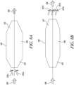
- FIG. 9A and 9B A further alternative form of the flow modulator 120A is illustrated in Figures 9A and 9B .
- the exhaust portion 127 of the hollow vane 120 is formed as the flow modulator 120A.
- the exhaust portion 127 is configured to change its shape in response to the user requirement to change the ratio of the mass airflows between the hollow vane 120 and the channel 124.
- the exhaust portion 127 is formed from a shape memory alloy material.
- the temperature of the vane airflow 106 will increase and the flow modulator 120A will open to thereby allow increased vane mass airflow Flowvane.
- the vane airflow 106 will have a lower temperature, causing the flow modulator 120A to close and restrict the vane mass airflow Flow Vane . This will therefore reduce the aerodynamic losses associated with flow through the hollow vanes 120 when the heat transfer capability of the heat transfer elements 112 is not required.
- the heat exchanger module 110 is in fluid communication with the fan assembly 130 by an inlet duct 160.
- the heat exchange module 110 has an axial length 115 of 0.4m, this being 0.4 times the fan diameter of 0.9m.
- the inlet duct 160 extends between a downstream-most face of the heat transfer elements and an upstream-most face of the fan assembly.
- the inlet duct 160 is linear.
- the inlet duct 160 may be curved or convoluted.
- the inlet duct 160 has a fluid path length 164 of 3.6m, this being 4.0 times the fan diameter of 0.9m.
- the fluid path length 164 extends along a central axis 162 of the inlet duct 160.
- the heat exchanger module 110 has a flow area (A HEX ) 118.
- the heat exchanger module flow area 118 is the cross-sectional area of the heat exchanger module 110 through which an air flow 104 passes before being ingested by the fan assembly 130.
- the heat exchanger module flow area 118 has an annular cross-section and corresponds directly to the shape of the air flow passing through the heat exchanger module 110.
- the fan assembly 130 has a corresponding flow area (A FAN ) 138.
- the fan assembly flow area 138 is the cross-sectional area of the fan assembly 130 through which an air flow 104 passes before separating into a core engine flow and a bypass flow.
- the fan assembly flow area 138 has an annular shape since it corresponds to the annular area swept by the fan blades 132.
- the heat exchanger module flow area 118 is equal to the fan assembly flow area 138, and the corresponding ratio of A HEX /A FAN is equal to 1.0.
- the heat exchanger module 110 has a flow diameter (E) 116, which is the diameter of the air flow passing through the heat exchanger module 110.
- E flow diameter
- the heat exchanger module flow diameter 116 is equal to the fan diameter 136.
- the heat exchanger module 110 comprises a plurality of heat transfer elements 112 for the transfer of heat energy from a first fluid 190 contained within the heat transfer elements 112 to an airflow 104 passing over a surface 113 of the heat transfer elements 112 prior to entry of the airflow 104 into the fan assembly 130.
- the first fluid 190 is a mineral oil.
- the first fluid 190 may be an alternative heat transfer fluid such as, for example, a water-based fluid, or the fuel used by the turbofan gas turbine engine.
- the heat transfer elements 112 have a conventional tube and fin construction and will not be described further.
- the heat transfer elements may have a different construction such as, for example, plate and shell.
- the turbofan gas turbine engine 100 further comprises an outer housing 170.
- the outer housing 170 fully encloses the sequential arrangement of the heat exchanger module 110, inlet duct 160, fan assembly 130, compressor module 140, and turbine module 150.
- the outer housing 170 defines a bypass duct 180 between the outer housing 170 and the core engine components (comprising inter alia the compressor module 140 and the turbine module 150).
- the bypass duct 180 has a generally axi-symmetrical annular cross-section extending over the core engine components.
- the bypass duct 180 may have a non-symmetric annular cross-section or may not extend around a complete circumference of the core engine components.
- a turbofan gas turbine engine according to a second embodiment of the disclosure is designated generally by the reference numeral 200.
- Features of the turbofan gas turbine engine 200 which correspond to those of turbofan gas turbine engine 100 have been given corresponding reference numerals for ease of reference.
- the turbofan gas turbine engine 200 comprises in axial flow sequence, a heat exchanger module 210, a fan assembly 130, a compressor module 140, and a turbine module 150.
- the fan assembly 130, compressor module 140, and turbine module 150 correspond directly to the those of the first embodiment described above.
- the heat exchanger module 210 comprises a plurality of heat transfer elements 212 and is also in fluid communication with the fan assembly 130 by an inlet duct 260.
- the inlet duct 260 extends between a downstream-most face of the heat transfer elements and an upstream-most face of the fan assembly.
- the inlet duct 260 has a fluid path length 264 along a central axis 162 of the inlet duct 260 of 2.4m, this being 2.7 times the fan diameter of 0.9m.
- the heat exchanger module 210 has a flow area (A HEX ) 218.
- the heat exchanger module flow area 118 is annular in cross-section.
- the heat transfer elements 212 do not extend completely across that cross-section of the heat exchange module 210 that is available for the flow 104. In other words, there is a radially proximal portion of the cross-section of the heat transfer module across which there are no heat transfer elements 212.
- the fan assembly 130 has a flow area (A FAN ) 138 that, as described above, has an annular shape corresponding to the annular area swept by the fan blades 132.
- the heat exchanger module flow area 218 is equal to the fan assembly flow area 138.
- the corresponding ratio of A HEX /A FAN is equal to 1.0.
- the heat exchanger module 210 has a flow diameter 216.
- the heat exchanger module flow diameter 216 is greater than the fan diameter 136.
- the turbofan gas turbine engine 200 further comprises an outer housing 270.
- the outer housing 170 fully encloses the sequential arrangement of the heat exchanger module 210, inlet duct 260, fan assembly 130, compressor module 140, and turbine module 150.
- the outer housing 270 also defines an annular bypass duct 180 between the outer housing 170 and the core engine components
- turbofan gas turbine engine 200 functions in the same manner as described above in relation to the turbofan gas turbine engine 100 of the first embodiment.
- the invention includes methods that may be performed using the subject devices.
- the methods may comprise the act of providing such a suitable device.
- Such provision may be performed by the end user.
- the "providing" act merely requires the end user obtain, access, approach, position, set-up, activate, power-up or otherwise act to provide the requisite device in the subject method.
Landscapes
- Engineering & Computer Science (AREA)
- Chemical & Material Sciences (AREA)
- Combustion & Propulsion (AREA)
- Mechanical Engineering (AREA)
- General Engineering & Computer Science (AREA)
- Physics & Mathematics (AREA)
- Thermal Sciences (AREA)
- Structures Of Non-Positive Displacement Pumps (AREA)
Description
- The present disclosure relates to a circumferential vane array accommodating a heat exchanger and particularly to a circumferential vane array accommodating a heat exchanger, for use with a turbofan gas turbine engine.
- A conventional turbofan gas turbine engine uses heat exchangers to cool a variety of fluids including inter alia air, fuel and oil. Typically, such heat exchangers use bypass air or an air offtake from the compressor as the cooling medium. The heat exchanger itself may be positioned in the bypass duct or externally to the engine with the corresponding ducting.
- The use of bypass air or a compressor offtake stream as the cooling medium in a heat exchanger will adversely affect the performance of the engine, for example by reducing specific thrust or increasing specific fuel consumption. Alternatively, or additionally, such offtakes can adversely affect engine performance, for example by reducing surge margin.
- In a further alternative conventional arrangement, an air flow to provide the cooling medium in a heat exchanger may be drawn separately from the air flow through the gas turbine engine. For example, in an airframe application the air flow providing the cooling medium may be drawn from an air intake or duct separate from the engine.
-
EP 1 916 399 A2 discloses a method for assembling a turbine engine, including assembling a heat exchanger assembly that includes at least a radially inner plate, a radially outer plate, and a heat exchanger coupled between the radially inner and outer plates, forming the heat exchanger assembly such that the heat exchanger assembly has a substantially arcuate shape. The method then requires coupling the heat exchanger to a fan casing such that the heat exchanger is positioned upstream or downstream from the fan assembly. -
EP 2 085 600 A2 discloses a thermal management system including at least one heat exchanger in communication with a bypass flow of a gas turbine engine. The placement of the heat exchanger(s) minimizes weight and aerodynamic losses and contributes to overall performance increase over traditional ducted heat exchanger placement schemes. -
EP 3023 724 A1 discloses a heat exchanger apparatus including a surface cooler and a passive automatic retraction and extension system coupled to the surface cooler. The surface cooler has one or more fluid flow channels configured for the passage therethrough of a heat transfer fluid to be cooled. The heat transfer fluid in a heat transfer relation on an interior side of said one or more fluid flow channels. The surface cooler including a plurality of fins projecting from an outer surface thereof. The passive automatic retraction and extension system including a thermal actuation component responsive to a change in temperature of at least one of the heat transfer fluid and a cooling fluid flow so as to actuate a change in a geometry of the surface cooler. -
GB 2 238 080 A - As used herein, a range "from value X to value Y" or "between value X and value Y", or the likes, denotes an inclusive range; including the bounding values of X and Y. As used herein, the term "axial plane" denotes a plane extending along the length of an engine, parallel to and containing an axial centreline of the engine, and the term "radial plane" denotes a plane extending perpendicular to the axial centreline of the engine, so including all radial lines at the axial position of the radial plane. Axial planes may also be referred to as longitudinal planes, as they extend along the length of the engine. A radial distance or an axial distance is therefore a distance in a radial or axial plane, respectively.
- According to a first aspect of the present disclosure there is provided a turbofan gas turbine engine comprising, in axial flow sequence, a heat exchanger module, a fan assembly, a compressor module, a turbine module, and an exhaust module, the fan assembly comprising a plurality of fan blades defining a fan diameter (D), the heat exchanger module being in fluid communication with the fan assembly by an inlet duct, the heat exchanger module further comprising a plurality of radially-extending hollow vanes arranged in a circumferential array, with a channel extending axially between each pair of adjacent hollow vanes, each of the hollow vanes accommodating at least one heat transfer element for the transfer of heat from a first fluid contained within the or each heat transfer element to a corresponding vane airflow passing through the hollow vane and over a surface of the or each heat transfer element, each of the hollow vanes further comprising a flow modulator, the flow modulator being configured to actively regulate the vane airflow as a proportion of a total airflow entering the heat exchanger module in response to a user requirement.
- The active regulation of the vane airflow as a proportion of the total airflow entering the heat exchanger module enables a user to determine the proportion of the intake air flow that passes through the hollow vanes and therefore the proportion of the intake air that passes over the heat transfer elements.
- Since the vane airflow through the hollow vanes incurs an aerodynamic penalty over the channel airflow that passes between adjacent vanes, by regulating the vane airflow to only that required to maintain a required level of heat energy rejection to the vane airflow, a user can maximise the aerodynamic efficiency of the turbofan engine.
- in one example configuration a user may require the vane air flow to be, for example, one third (⅓) of the channel air flow in order for the vane air flows to provide for efficient transfer of heat energy from the first fluid through the heat transfer elements. In alternative configurations, the proportion of the total air flow entering the heat exchange module that makes up the vane air flow may be greater or less than one third (⅓).
- Optionally, the airflow entering the heat exchange module is divided between the set of vane airflows through each hollow vane, each vane airflow having a vane mass flow rate FlowVane, and a set of channel airflows through each channel, each channel air flow having a channel mass flow rate FlowChan, and the flow modulator is configured to actively regulate a ratio between a sum of the vane mass flow rates FlowVaneTot and a sum of the channel mass flow rates FlowChanTot.
- As outlined above, the heat energy rejected by the heat transfer elements is transferred to the vane air flows passing through the hollow vanes and over the heat transfer elements. Specifically, the vane mass flow rate is a controlling factor in the quantity of heat energy transferred to the vane air flows. Consequently, the ability for a user to regulate the proportion of the intake flow that passes through the hollow vanes thereby enables the user to control the quantity of heat energy transferred to the vane air flows.
- Optionally, each hollow vane comprises, in axial flow sequence, an inlet portion, the at least one heat transfer element, and an exhaust portion, the inlet portion comprising a flow modulator, the flow modulator being configured to restrict the vane airflow in response to the user requirement.
- In one arrangement of the present disclosure, the flow modulator comprises one or more first vanes positioned at the inlet portion. The first vanes may be positioned upstream of an inlet aperture to the hollow vane. Alternatively, the flow modulator may comprise one or more first vanes that form the inlet portion of the hollow vane. In a further alternative arrangement, the first vanes may be positioned at the inlet aperture to the hollow vane. The flow modulator in the form of the first vanes can be actively regulated by a user to limit the vane air flow entering the hollow vane and thus to limit the vane mass flow rate.
- Optionally, each hollow vane comprises, in axial flow sequence, an inlet portion, the at least one heat transfer element, and an exhaust portion, the exhaust portion comprising a flow modulator, the flow modulator being configured to restrict the vane airflow in response to the user requirement.
- In another arrangement of the present disclosure, the flow modulator comprises one or more second vanes positioned at the exhaust portion. Alternatively, the exhaust portion of the hollow vane may be formed by the flow modulator in the form of the second vanes.
- In yet another arrangement, the exhaust portion of the hollow vane may comprise the flow modulator. For example, the flow modulator forming the exhaust portion may comprise a shape memory material that is configured to restrict the vane airflow exhausted from the hollow vane in response to the user requirement.
- In each of these arrangements, the flow modulator in the form of the second vanes may be actively regulated by a user to restrict the vane air flow exhausted from the hollow vane and in this way to limit the vane mass flow rate.
- Optionally, the fan diameter D is within the range of 0.3m to 2.0m, preferably within the range 0.4m to 1.5m, and more preferably in the range of 0.7m to 1.0m.
- In one embodiment of the disclosure, the fan diameter is 0.9m.
- Consequently, for the same heat energy loading rejected to the air flow through the heat exchanger, the loss in propulsive efficiency of the turbofan engine is proportionately smaller for a large diameter (for example, approximately 1.5 to 2.0m in diameter) turbofan engine than for a small diameter turbofan engine.
- The fan tip radius, measured between a centreline of the engine and an outermost tip of each fan blade at its leading edge, may be in the range from 95 cm to 200 cm, for example in the range from 110 cm to 150 cm, or alternatively in the range from 155 cm to 200 cm. The fan tip radius may be greater than any of: 110 cm, 115 cm, 120 cm, 125 cm, 130 cm, 135cm, 140 cm, 145 cm, 150 cm, 155 cm, 160 cm, 165 cm, 170 cm, 175 cm, 180 cm, 185 cm, 190 cm or 195 cm. The fan tip radius may be around 110 cm, 115 cm, 120 cm, 125 cm, 130 cm, 135cm, 140 cm, 145 cm, 150 cm, 155 cm, 160 cm, 165 cm, 170 cm, 175 cm, 180 cm, 185 cm, 190 cm or 195 cm. The fan tip radius may be greater than 160 cm.
- The fan tip radius may be in the range from 95 cm to 150 cm, optionally in the range from 110 cm to 150 cm, optionally in the range of from 110 cm to 145 cm, and further optionally in the range from 120 cm to 140 cm.
- The fan tip radius may be in the range from 155 cm to 200 cm, optionally in the range from 160 cm to 200 cm, and further optionally in the range from 165 cm to 190 cm.
- Optionally, the heat exchanger module has a flow area AHEX and the fan module has a flow area AFAN, and a ratio of AFAN to AHEX being in the range of 0.3 to 0.8.
- The flow area is to be understood to mean a cross-sectional area of the air flow taken perpendicularly to a central axis of the flow in the flow direction. In other words, for the heat exchanger module the flow area AHEX corresponds to the cross-sectional area of the heat exchanger module through which the flow passes. Likewise, for the fan assembly the flow area AFAN corresponds to the cross-sectional area of the fan assembly through which the flow passes.
- In one arrangement of the present disclosure, the flow area of the heat exchanger module has an annular profile and extends over only a radially outward circumferential portion of the flow area of the fan assembly. In other words, the air flow entering a radially proximal portion of the flow area of the fan assembly does not pass through the heat exchanger assembly and simply enters the fan assembly. In one arrangement, the radially outward circumferential portion of the flow area of the fan assembly amounts to 60% of the flow area of the fan assembly.
- In another arrangement of the disclosure, the flow area of the heat exchanger module extends completely over the flow area of the fan assembly.
- Optionally, the heat exchanger module has a fluid path diameter E, wherein the fluid path diameter E is greater than the fan diameter D.
- In one embodiment, the heat exchanger module has a fluid path diameter E that is greater than the fan diameter D. In this embodiment, the inlet duct that connects the heat exchanger module to the fan assembly has a diameter than converges from an exit from the heat exchanger module to an entrance to the fan assembly.
- Optionally, the turbofan gas turbine engine further comprises an outer housing, the outer housing enclosing the sequential arrangement of heat exchanger module, fan assembly, compressor module, and turbine module, an annular bypass duct being defined between the outer housing and the sequential arrangement of compressor module, turbine module, and exhaust module, a bypass ratio being defined as a ratio of a mass air flow rate through the bypass duct to a mass air flow rate through the sequential arrangement of compressor module, turbine module, and exhaust module, and wherein the bypass ratio is less than 2.0.
- A turbofan engine having a bypass ratio (BPR) of less than approximately 2.0 will have a generally smaller bypass duct (the annular duct surrounding the core gas turbine engine) than a turbofan engine having a BPR greater than approximately 2.0. For a turbofan engine with a BPR greater than, say, 2.0, the correspondingly larger bypass duct volume provides more scope for positioning a heat exchanger within the bypass duct than would be the case for a low BPR turbofan engine.
- Optionally, the fan assembly has two or more fan stages, at least one of the fan stages comprising a plurality of fan blades defining the fan diameter D.
- In one arrangement, the fan assembly has two fan stages with both fan stages comprising a plurality of fan blades defining the same fan diameter. Alternatively, each of the fan stages may have different fan diameters.
- Optionally, in use, an airflow entering the heat exchanger module with a mean velocity of 0.4M, is divided between the set of vane airflows having a mean velocity of 0.2M, and the set of channel airflows having a mean velocity of 0.6M.
- In one arrangement of the present disclosure, the inlet and exhaust portions of the hollow vane may act as a diffuser to slow the air flow entering the hollow vane. In other words, the vane mass air flow is reduced from the mass air flow of the air flow entering the heat exchanger module. In this arrangement, the channel air flow through the channels between circumferentially adjacent pairs of hollow vanes is increased to maintain continuity of flow.
- According to another aspect of the present disclosure, not forming part of the present invention, there is provided a method of operating an aircraft comprising the gas turbine engine according to the first aspect, the method comprising taking off from a runway, wherein the maximum rotational speed of the turbine during take-off is in the range of from 8500 rpm to 12500 rpm.
- The maximum take-off rotational fan speed may be in a range between 8500 rpm to 12500 rpm. Optionally, for example for an engine with a fan tip radius in the range from 25 cm to 40 cm, the maximum take-off rotational fan speed may be in a range between 9000 rpm to 11000 rpm. Optionally, for example for an engine with a fan tip radius in the range from 35 cm to 50 cm, the maximum take-off rotational fan speed may be in a range between 8500 rpm to 10500 rpm.
- According to another aspect of the present disclosure there is provided a method of operating a turbofan gas turbine engine, the gas turbine engine comprising, in axial flow sequence, a heat exchanger module, an inlet duct, a fan assembly, a compressor module, a turbine module, and an exhaust module, and wherein the method comprises the steps of:
- (i) providing the fan assembly, the compressor module, and the turbine module;
- (ii) positioning the heat exchanger module in fluid communication with the fan assembly by the inlet duct;
- (iii) providing the heat exchanger module with a plurality of radially-extending hollow vanes arranged in a circumferential array, with a channel extending axially through the heat exchanger module between each pair of adjacent hollow vanes, such that an airflow entering the heat exchange module is divided between a set of vane airflows through each of the hollow vanes, each vane airflow having a vane mass flow rate Flowvane, and a set of channel airflows FlwChan through each of the channels, each channel air flow having a channel mass flow rate FlowChan,;
- (iv) providing each of the hollow vanes with, at least one heat transfer element, and a flow modulator;
- (v) operating the gas turbine engine including active control of the flow modulator to regulate a sum of the vane mass flow rates FlowVaneTot as a proportion of a total air mass flow entering the heat exchanger module in response to a user requirement.
- The active regulation of the vane airflow as a proportion of the total airflow entering the heat exchanger module enables a user to determine the proportion of the intake air flow that passes through the hollow vanes and therefore the proportion of the intake air that passes over the heat transfer elements.
- Since the vane airflow through the hollow vanes incurs an aerodynamic penalty over the channel airflow that passes between adjacent vanes, by regulating the vane airflow to only that required to maintain a required level of heat energy rejection to the vane airflow, a user can maximise the aerodynamic efficiency of the turbofan engine.
- in one example configuration a user may require the vane air flow to be, for example, one third (⅓) of the channel air flow in order for the vane air flows to provide for efficient transfer of heat energy from the first fluid through the heat transfer elements. In alternative configurations, the proportion of the total air flow entering the heat exchange module that makes up the vane air flow may be greater or less than one third (⅓).
- According to an aspect of the disclosure, there is provided a method of operating an aircraft comprising a turbofan gas turbine engine as described and/or claimed herein. The operation according to this aspect may include (or may be) operation at the midcruise of the aircraft, as defined elsewhere herein.
- Other aspects of the disclosure provide devices, methods and systems which include and/or implement some or all of the actions described herein. The illustrative aspects of the disclosure are designed to solve one or more of the problems herein described and/or one or more other problems not discussed.
- There now follows a description of an embodiment of the disclosure, by way of nonlimiting example, with reference being made to the accompanying drawings in which:
-
Figure 1 shows a schematic part-sectional view of a turbofan gas turbine engine according to the prior art; -
Figure 2 shows a schematic part-sectional view of a turbofan gas turbine engine according to a first embodiment of the disclosure; -
Figure 3 shows a schematic part-sectional view of a turbofan gas turbine engine according to a second embodiment of the disclosure; -
Figure 4 shows a perspective schematic view of the heat exchanger module of the turbofan engine ofFigure 2 showing the circumferential array of vanes forming the heat exchanger module; -
Figure 5 shows a schematic part-sectional view of a part of the vane array of the heat exchanger module ofFigure 4 ; -
Figure 6 shows a schematic axial sectional view across one of the vanes of the vane array of the heat exchanger module ofFigure 4 ; -
Figure 7 shows a perspective schematic view of a heat transfer element of the heat exchanger module ofFigure 4 ; -
Figure 8A shows a schematic view of the vane ofFigure 6 with a flow modulator in the form of first vanes arranged upstream of the inlet to the vane; -
Figure 8B ; shows a schematic view of the vane ofFigure 6 with a flow modulator in the form of second vanes arranged downstream of the exhaust from the vane; -
Figure 8C shows a schematic view of the vane ofFigure 6 with a flow modulator in the form of a VIGV array; -
Figure 9A shows a schematic axial sectional view across one of the vanes of the vane array of the heat exchanger module ofFigure 4 with the flow modulator forming the exhaust portion of the vane, and the modulator in a 'open' position; and -
Figure 9A shows a schematic axial sectional view of the vane ofFigure 9 with the modulator in a 'closed' position. - It is noted that the drawings may not be to scale. The drawings are intended to depict only typical aspects of the disclosure, and therefore should not be considered as limiting the scope of the disclosure. In the drawings, like numbering represents like elements between the drawings.
-
Figure 1 illustrates a conventional turbofangas turbine engine 10 having a principalrotational axis 9. Theengine 10 comprises anair intake 12 and a two-stagepropulsive fan 13 that generates two airflows: a core airflow A and a bypass airflow B. Thegas turbine engine 10 comprises a core 11 that receives the core airflow A. - The
engine core 11 comprises, in axial flow series, a low-pressure compressor 14, a high-pressure compressor 15,combustion equipment 16, a high-pressure turbine 17, an intermediate-pressure turbine 18, a low-pressure turbine 19 and acore exhaust nozzle 20. Anacelle 21 surrounds thegas turbine engine 10 and defines abypass duct 22 and abypass exhaust nozzle 18. The bypass airflow B flows through thebypass duct 22. Thefan 13 is attached to and driven by the low-pressure turbine 19 via ashaft 26. - In use, the core airflow A is accelerated and compressed by the low-
pressure compressor 14 and directed into the high-pressure compressor 15 where further compression takes place. The compressed air exhausted from the high-pressure compressor 15 is directed into thecombustion equipment 16 where it is mixed with fuel and the mixture is combusted. The resultant hot combustion products then expand through, and thereby drive, the high-pressure, intermediate-pressure, and low-pressure turbines nozzle 20 to provide some propulsive thrust. The high-pressure turbine 17 drives the high-pressure compressor 15 by a suitable interconnectingshaft 27. The low-pressure compressor 14 drives the intermediate-pressure turbine 18 via ashaft 28. - Note that the terms "low-pressure turbine" and "low-pressure compressor" as used herein may be taken to mean the lowest pressure turbine stages and lowest pressure compressor stages (i.e. not including the fan 13) respectively and/or the turbine and compressor stages that are connected together by the interconnecting
shaft 26 with the lowest rotational speed in the engine. In some literature, the "low-pressure turbine" and "low-pressure compressor" referred to herein may alternatively be known as the "intermediate-pressure turbine" and "intermediate-pressure compressor". Where such alternative nomenclature is used, thefan 13 may be referred to as a first, or lowest pressure, compression stage. - Other turbofan gas turbine engines to which the present disclosure may be applied may have alternative configurations. For example, such engines may have an alternative number of fans and/or compressors and/or turbines and/or an alternative number of interconnecting shafts. By way of further example, the gas turbine engine shown in
Figure 1 has asplit flow nozzle bypass duct 22 has itsown nozzle 23 that is separate to and radially outside thecore engine nozzle 20. However, this is not limiting, and any aspect of the present disclosure may also apply to engines in which the flow through thebypass duct 22 and the flow through thecore engine 11 are mixed, or combined, before (or upstream of) a single nozzle, which may be referred to as a mixed flow nozzle. One or both nozzles (whether mixed or split flow) may have a fixed or variable area. Whilst the described example relates to a turbofan engine, the disclosure may apply, for example, to any type of gas turbine engine, such as an open rotor (in which the fan stage is not surrounded by a nacelle) or turboprop engine, for example. - The geometry of the turbofan
gas turbine engine 10, and components thereof, is defined by a conventional axis system, comprising an axial direction (which is aligned with the rotational axis 9), a radial direction (in the bottom-to-top direction inFigure 1 ), and a circumferential direction (perpendicular to the page in theFigure 1 view). The axial, radial and circumferential directions are mutually perpendicular. - Referring to
Figure 2 , a turbofan gas turbine engine according to a first embodiment of the disclosure is designated generally by thereference numeral 100. The turbofangas turbine engine 100 comprises in axial flow sequence, aheat exchanger module 110, afan assembly 130, acompressor module 140, aturbine module 150, and anexhaust module 156. - In the present arrangement, the
fan assembly 130 comprises twofan stages 131, with eachfan stage 131 comprising a plurality offan blades 132. In the present arrangement eachfan stage 131 has thesame fan diameter 136, with the respective plurality of fan blades defining a fan diameter of 0.9m. In an alternative arrangement, the twofan stages 131 may havedifferent fan diameters 136 each defined by the corresponding plurality offan blades 132. As previously mentioned, the fan diameter (D) 136 is defined by a circle circumscribed by the leading edges of the respective plurality offan blades 132. -
Figure 4 shows a perspective view of theheat exchanger module 110 andfan assembly 130 of the turbofangas turbine engine 100 according to the first embodiment. Theheat exchanger module 110 comprises twelve radially extendingvanes 120 arranged in an equi-spacedcircumferential array 122 with achannel 124 extending axially between each pair of adjacenthollow vanes 120. Alternative embodiments may have more or fewerradially extending vanes 120. - Each of the
vanes 120 is hollow and comprises fourheat transfer elements 112 arranged in a 2x2 configuration extending axially along the hollow interior of thevane 120, as shown inFigure 6 . Alternative embodiments may not have aheat transfer element 112 within eachvane 120 or may have a different number ofheat transfer elements 112 in anysingle vane 120. - Each of the
heat transfer elements 112 has a corresponding swept area, which is the area of theheat transfer element 112 that is contacted by theair flow 104. In the present arrangement, the total swept heat transfer element area (AHTE) is the sum of the swept area of each of the individualheat transfer elements 112. - Each
vane 120 is configured to allow theincoming airflow 104 passing through theheat exchange module 110 to pass through the hollow portion of thevane 120 and thence to flow over the respectiveheat transfer element 112. In this way heat energy is transferred from the first fluid 190 to theair flow 104. - In use, as illustrated in
Figure 5 , anairflow 104 entering theheat exchanger module 110 is divided between a set ofvane airflows 106 through each of thehollow vanes 120 and a set ofchannel airflows 108 through each of thechannels 124. Each of thevane airflows 106 has a vane mass flowrate Flowvane. Each of thechannel airflows 108 has a channel mass flowrate FlowChan. - A Vane Airflow Ratio parameter VAR is defined as:

- In the present embodiment, the VAR parameter is 1.0. In other words, in this arrangement the
incoming airflow 104 is divided equally between thevane airflows 106 and the channel airflows108. -
Figure 6 shows an axial cross-section through one of thehollow vanes 120 and corresponds to the Section on `C-C' fromFigure 5 . Each of thehollow vanes 120 comprises, in axial flow sequence, aninlet portion 125, aheat transfer portion 126, and anexhaust portion 127. - The
inlet portion 125 comprises adiffuser element 128. Thediffuser element 128 takes the form of an axially-extendingfirst duct 128A. Thefirst duct 128A has anaxial cross-section 128B that has a linearlydivergent profile 128C. In use, thediffuser element 128 acts to slow theincoming airflow 104 to thevane airflow 106. Thediffuser element 128 is sized such that the vane mass flow rate FlowVane is less than the channel mass flow rate FlowChan by a user-defined margin. - The
heat transfer portion 126 accommodates theheat transfer elements 112. Finally, theexhaust portion 127 comprises an axially-extendingsecond duct 127A having anaxial cross-section 127B that in turn has a linearlyconvergent profile 127C. -
Figure 7 shows a perspective schematic view of a radially outward facing surface of ahollow vane 120. As outlined above, in this embodiment each vane is provided with fourheat transfer elements 112 arranged in a 2x2 formation. Each of theheat transfer elements 112 has afluid inlet 112A and a correspondingfluid outlet 112B. Thefluid inlet 112A provides a feed of hot oil (not shown) to the respectiveheat transfer element 112. Each of thefluid inlets 112A is provided with anactuatable inlet valve 112C that can be switched to cut off the fluid flow into theheat transfer element 112. Additionally, each of thefluid outlets 112B is provided with anactuatable inlet valve 112D that can also be controlled to cut off the fluid flow leaving theheat transfer element 112. - Each of the
fluid inlet valves 112C is provided with afluid pressure sensor 112F that monitors the pressure of the oil flowing through theinlet 112A. In response to a sensed drop in the fluid pressure as measured by thepressure sensor 112F, theinlet valve 112C may be actuated to cut-off the oil flow through the respectiveheat transfer element 112. In this arrangement, theoutlet valve 112D is also actuated in response to a loss of oil pressure to thereby isolate the correspondingheat transfer element 112 from the remaining oil flow. - Each of the
fluid outlets 112B is provided with afluid flow sensor 112E. In the event of a drop in fluid flow rate as detected by theflow sensor 112E, the correspondingfluid outlet valve 112D (and in this arrangement, the correspondingfluid inlet valve 112C) can be actuated to cut off the oil flow through theheat transfer element 112. In addition to, or in an alternative to, thediffuser element 128 described above, thehollow vane 120 is provided with aflow modulator 120A. Theflow modulator 120A is configured to actively regulate thevane airflow 106 as a proportion of atotal airflow 104 entering theheat exchanger module 110 in response to a user requirement. In other words, theflow modulator 120A provides a user with the ability to actively change the vane mass flowrate FlowVaneTot as a proportion of theairflow 104 entering the turbofan engine. - In one arrangement, shown in
Figure 8A , theflow modulator 120A takes the form offirst vanes 125A positioned upstream of theinlet portion 125 of thehollow vane 120. Thefirst vanes 125A are actuatable to restrict thevane airflow 106 in response to the user requirement to change the ratio of the mass airflows between the hollow vane and the channel. - The
first vanes 125A also provide a measure of protection to theheat transfer elements 112 positioned inside thehollow vane 120 from foreign object damage caused by debris or other objects entering thehollow vane 120. -
Figure 8B illustrates an alternative arrangement for theflow modulator 120A in whichsecond vanes 127D are positioned downstream of theexhaust portion 127 of thehollow vane 120. Thesesecond vanes 127D are actuatable to restrict thevane airflow 106 in response to the user requirement to change the ratio of the mass airflows between thehollow vane 120 and thechannel 124. - In a further alternative arrangement,
Figure 8C illustrates aflow modulator 127E that takes the form of theexhaust portion 127 itself. In this arrangement, theheat exchange module 110 is close-coupled to an actuatable variable inlet guide vane (VIGV)array 127E. The close-coupling configuration provides for thefan assembly 130 to effectively 'suck' theincoming air flow 104 through both thehollow vanes 120 and thechannels 124. Such an arrangement also enables theinlet duct 160 to be shorter provides for an axially more compact turbofan gas turbine engine. - A further alternative form of the
flow modulator 120A is illustrated inFigures 9A and 9B . In this arrangement theexhaust portion 127 of thehollow vane 120 is formed as theflow modulator 120A. In other words, theexhaust portion 127 is configured to change its shape in response to the user requirement to change the ratio of the mass airflows between thehollow vane 120 and thechannel 124. - In the example shown in
Figures 9A and 9B theexhaust portion 127 is formed from a shape memory alloy material. When theheat transfer elements 112 are in use the temperature of thevane airflow 106 will increase and theflow modulator 120A will open to thereby allow increased vane mass airflow Flowvane. Conversely when theheat transfer elements 112 are not in use thevane airflow 106 will have a lower temperature, causing theflow modulator 120A to close and restrict the vane mass airflow FlowVane. This will therefore reduce the aerodynamic losses associated with flow through thehollow vanes 120 when the heat transfer capability of theheat transfer elements 112 is not required. - The
heat exchanger module 110 is in fluid communication with thefan assembly 130 by aninlet duct 160. Theheat exchange module 110 has anaxial length 115 of 0.4m, this being 0.4 times the fan diameter of 0.9m. - The
inlet duct 160 extends between a downstream-most face of the heat transfer elements and an upstream-most face of the fan assembly. In the present arrangement, theinlet duct 160 is linear. However, in other arrangements theinlet duct 160 may be curved or convoluted. - The
inlet duct 160 has a fluid path length 164 of 3.6m, this being 4.0 times the fan diameter of 0.9m. The fluid path length 164 extends along acentral axis 162 of theinlet duct 160. - As outlined earlier, the
heat exchanger module 110 has a flow area (AHEX) 118. The heat exchangermodule flow area 118 is the cross-sectional area of theheat exchanger module 110 through which anair flow 104 passes before being ingested by thefan assembly 130. In the present arrangement, the heat exchangermodule flow area 118 has an annular cross-section and corresponds directly to the shape of the air flow passing through theheat exchanger module 110. - The
fan assembly 130 has a corresponding flow area (AFAN) 138. The fanassembly flow area 138 is the cross-sectional area of thefan assembly 130 through which anair flow 104 passes before separating into a core engine flow and a bypass flow. The fanassembly flow area 138 has an annular shape since it corresponds to the annular area swept by thefan blades 132. - In the present arrangement, the heat exchanger
module flow area 118 is equal to the fanassembly flow area 138, and the corresponding ratio of AHEX/AFAN is equal to 1.0. - The
heat exchanger module 110 has a flow diameter (E) 116, which is the diameter of the air flow passing through theheat exchanger module 110. In the present arrangement, the heat exchanger module flow diameter 116 is equal to thefan diameter 136. - The
heat exchanger module 110 comprises a plurality ofheat transfer elements 112 for the transfer of heat energy from a first fluid 190 contained within theheat transfer elements 112 to anairflow 104 passing over a surface 113 of theheat transfer elements 112 prior to entry of theairflow 104 into thefan assembly 130. In the present embodiment, the first fluid 190 is a mineral oil. In other arrangements, the first fluid 190 may be an alternative heat transfer fluid such as, for example, a water-based fluid, or the fuel used by the turbofan gas turbine engine. - The
heat transfer elements 112 have a conventional tube and fin construction and will not be described further. In an alternative arrangement, the heat transfer elements may have a different construction such as, for example, plate and shell. - The turbofan
gas turbine engine 100 further comprises anouter housing 170. Theouter housing 170 fully encloses the sequential arrangement of theheat exchanger module 110,inlet duct 160,fan assembly 130,compressor module 140, andturbine module 150. Theouter housing 170 defines abypass duct 180 between theouter housing 170 and the core engine components (comprising inter alia thecompressor module 140 and the turbine module 150). In the present arrangement, thebypass duct 180 has a generally axi-symmetrical annular cross-section extending over the core engine components. In other arrangements, thebypass duct 180 may have a non-symmetric annular cross-section or may not extend around a complete circumference of the core engine components. - Referring to
Figure 3 , a turbofan gas turbine engine according to a second embodiment of the disclosure is designated generally by thereference numeral 200. Features of the turbofangas turbine engine 200 which correspond to those of turbofangas turbine engine 100 have been given corresponding reference numerals for ease of reference. - The turbofan
gas turbine engine 200 comprises in axial flow sequence, aheat exchanger module 210, afan assembly 130, acompressor module 140, and aturbine module 150. - The
fan assembly 130,compressor module 140, andturbine module 150 correspond directly to the those of the first embodiment described above. - The
heat exchanger module 210 comprises a plurality of heat transfer elements 212 and is also in fluid communication with thefan assembly 130 by aninlet duct 260. As in the first embodiment, theinlet duct 260 extends between a downstream-most face of the heat transfer elements and an upstream-most face of the fan assembly. - The
inlet duct 260 has afluid path length 264 along acentral axis 162 of theinlet duct 260 of 2.4m, this being 2.7 times the fan diameter of 0.9m. - The
heat exchanger module 210 has a flow area (AHEX) 218. As in the first embodiment, the heat exchangermodule flow area 118 is annular in cross-section. However, in this arrangement the heat transfer elements 212 do not extend completely across that cross-section of theheat exchange module 210 that is available for theflow 104. In other words, there is a radially proximal portion of the cross-section of the heat transfer module across which there are no heat transfer elements 212. - The
fan assembly 130 has a flow area (AFAN) 138 that, as described above, has an annular shape corresponding to the annular area swept by thefan blades 132. - In the present arrangement, despite the heat exchanger module flow area 218 having different dimensions to the fan
assembly flow area 138, the heat exchanger module flow area 218 is equal to the fanassembly flow area 138. As for the first embodiment, the corresponding ratio of AHEX/AFAN is equal to 1.0. - The
heat exchanger module 210 has aflow diameter 216. The heat exchangermodule flow diameter 216 is greater than thefan diameter 136. - The turbofan
gas turbine engine 200 further comprises anouter housing 270. As with the first embodiment described above, theouter housing 170 fully encloses the sequential arrangement of theheat exchanger module 210,inlet duct 260,fan assembly 130,compressor module 140, andturbine module 150. Theouter housing 270 also defines anannular bypass duct 180 between theouter housing 170 and the core engine components - In use the turbofan
gas turbine engine 200 functions in the same manner as described above in relation to the turbofangas turbine engine 100 of the first embodiment. - It will be understood that the invention is not limited to the embodiments above-described and various modifications and improvements can be made without departing from the concepts described herein.
- The invention includes methods that may be performed using the subject devices. The methods may comprise the act of providing such a suitable device. Such provision may be performed by the end user. In other words, the "providing" act merely requires the end user obtain, access, approach, position, set-up, activate, power-up or otherwise act to provide the requisite device in the subject method.
- In addition, where a range of values is provided, it is understood that every intervening value, between the upper and lower limit of that range and any other stated or intervening value in that stated range, is encompassed within the invention.
Claims (11)
- A turbofan gas turbine engine (100) comprising, in axial flow sequence, a heat exchanger module (110), a fan assembly (130), a compressor module (140), a turbine module (150), and an exhaust module (156), the fan assembly (130) comprising a plurality of fan blades (132) defining a fan diameter (D), the heat exchanger module (110) being in fluid communication with the fan assembly (130) by an inlet duct (160), the heat exchanger module (110) further comprising a plurality of radially-extending hollow vanes (120) arranged in a circumferential array (122), with a channel (124) extending axially between adjacent hollow vanes (120), each of the hollow vanes (120) accommodating at least one heat transfer element (112) for the transfer of heat from a first fluid (190) contained within the or each heat transfer element (112) to a corresponding vane airflow (106) passing through the hollow vane (120) and over a surface of the or each heat transfer element (112), each of the hollow vanes (120) further comprising a flow modulator (120A), the flow modulator (120A) being configured to actively regulate the vane airflow (106) as a proportion of a total airflow (104) entering the heat exchanger module (110) in response to a user requirement.
- The turbofan gas turbine engine (100) as claimed in Claim 1, wherein the airflow (104) entering the heat exchange module (110) is divided between the set of vane airflows (106) through each hollow vane (120), each vane airflow (106) having a vane mass flow rate FlowVane, and a set of channel airflows (108) through each channel (124), each channel air flow (108) having a channel mass flow rate FlowChan, and the flow modulator (120A) is configured to actively regulate a ratio between a sum of the vane mass flow rates FlowVaneTot and a sum of the channel mass flow rates FlowChanTot.
- The turbofan gas turbine engine (100) as claimed in Claim 1 or Claim 2, wherein each hollow vane (120) comprises, in axial flow sequence, an inlet portion (125), the at least one heat transfer element (126), and an exhaust portion (127), and one or more first vanes (125A) are positioned upstream of the inlet portion (125), the first vanes (125A) being configured to restrict the vane airflow (106) in response to the user requirement.
- The turbofan gas turbine engine (100) as claimed in any one of Claims 1 to 3, wherein each hollow vane (120) comprises, in axial flow sequence, an inlet portion (125), the at least one heat transfer element (126), and an exhaust portion (127), and the exhaust portion (127) comprises a shape memory material that is configured to restrict the vane airflow (106) in response to the user requirement.
- The turbofan gas turbine engine (100) as claimed in any one of Claims 1 to 4, wherein the fan diameter D is within the range of 0.3m to 2.0m, preferably within the range 0.4m to 1.5m, and more preferably in the range of 0.7m to 1.0m.
- The turbofan gas turbine engine (100) as claimed in any one of Claims 1 to 5, wherein the heat exchanger module (110) has a flow area AHEX and the fan module (130) has a flow area AFAN, and a ratio of AFAN to AHEX being in the range of 0.3 to 0.8.
- The turbofan gas turbine engine (100) as claimed in any one of Claims 1 to 6, wherein the heat exchanger module (110) has a fluid path diameter E, wherein the fluid path diameter E is greater than the fan diameter D.
- The turbofan gas turbine engine (100) as claimed in any one of Claims 1 to 7, the turbofan gas turbine engine (100) further comprising an outer housing (170), the outer housing (170) enclosing the sequential arrangement of heat exchanger module (110), fan assembly (130), compressor module (140), and turbine module (150), an annular bypass duct (180) being defined between the outer housing (170) and the sequential arrangement of compressor module (140), turbine module (150), and exhaust module (156), a bypass ratio being defined as a ratio of a mass air flow rate through the bypass duct (180) to a mass air flow rate through the sequential arrangement of compressor module (140), turbine module (150), and exhaust module (156), and wherein the bypass ratio is less than 2.0.
- The turbofan gas turbine engine (100) as claimed in any one of Claims 1 to 8, wherein the fan assembly (130) has two or more fan stages (131), at least one of the fan stages (131) comprising a plurality of fan blades (132) defining the fan diameter D.
- The turbofan gas turbine engine (100) as claimed in any one of Claims 1 to 9, wherein, in use, an airflow (104) entering the heat exchanger module (110) with a mean velocity of 0.4M, is divided between the set of vane airflows (106) having a mean velocity of 0.2M, and the set of channel airflows having a mean velocity of 0.6M.
- A method of operating a turbofan gas turbine engine (100), the gas turbine engine (100) comprising, in axial flow sequence, a heat exchanger module (110), an inlet duct (160), a fan assembly (130), a compressor module (140), a turbine module (150), and an exhaust module (156), and wherein the method comprises the steps of:(i) providing the fan assembly (130), the compressor module (140), and the turbine module (150);(ii) positioning the heat exchanger module (110) in fluid communication with the fan assembly (130) by the inlet duct (160);(iii) providing the heat exchanger module (110) with a plurality of radially-extending hollow vanes (120) arranged in a circumferential array (122), with a channel (124) extending axially through the heat exchanger module (110) between adjacent hollow vanes (120), such that an airflow (104) entering the heat exchange module (110) is divided between a set of vane airflows (106) through each of the hollow vanes (120), each vane airflow (106) having a vane mass flow rate Flowvane, and a set of channel airflows FlwChan through each of the channels (124), each channel air flow (108) having a channel mass flow rate FlowChan,;(iv) providing each of the hollow vanes (120) with, at least one heat transfer element (112), and a flow modulator (120A);(v) operating the gas turbine engine (100) including active control of the flow modulator (120A) to regulate a sum of the vane mass flow rates FlowVaneTot as a proportion of a total air mass flow (104) entering the heat exchanger module (110) in response to a user requirement.
Applications Claiming Priority (1)
| Application Number | Priority Date | Filing Date | Title |
|---|---|---|---|
| GB2016008.1A GB2599693B (en) | 2020-10-09 | 2020-10-09 | A heat exchanger |
Publications (2)
| Publication Number | Publication Date |
|---|---|
| EP3981972A1 EP3981972A1 (en) | 2022-04-13 |
| EP3981972B1 true EP3981972B1 (en) | 2023-12-06 |
Family
ID=73460590
Family Applications (1)
| Application Number | Title | Priority Date | Filing Date |
|---|---|---|---|
| EP21200620.9A Active EP3981972B1 (en) | 2020-10-09 | 2021-10-04 | A heat exchanger |
Country Status (4)
| Country | Link |
|---|---|
| US (1) | US11649730B2 (en) |
| EP (1) | EP3981972B1 (en) |
| ES (1) | ES2968395T3 (en) |
| GB (1) | GB2599693B (en) |
Families Citing this family (3)
| Publication number | Priority date | Publication date | Assignee | Title |
|---|---|---|---|---|
| GB2599686A (en) * | 2020-10-09 | 2022-04-13 | Rolls Royce Plc | An improved turbofan gas turbine engine |
| US12228075B2 (en) * | 2022-12-09 | 2025-02-18 | General Electric Company | Integral engine inlet frame air-cooled oil cooling apparatus |
| DE102024115935A1 (en) * | 2024-06-07 | 2025-12-11 | MTU Aero Engines AG | Heat exchanger arrangement |
Family Cites Families (30)
| Publication number | Priority date | Publication date | Assignee | Title |
|---|---|---|---|---|
| US2474258A (en) * | 1946-01-03 | 1949-06-28 | Westinghouse Electric Corp | Turbine apparatus |
| GB2238080B (en) * | 1987-05-26 | 1991-10-09 | Rolls Royce Plc | Improved propulsion system for an aerospace vehicle |
| FR2723761B1 (en) * | 1994-08-18 | 1996-09-20 | Snecma | TURBOREACTOR EQUIPPED WITH A DEFROST SYSTEM ON THE INPUT HOUSING |
| CN1228591C (en) * | 2002-07-12 | 2005-11-23 | 株式会社电装 | Heat exchanger for cooling air |
| US7093359B2 (en) * | 2002-09-17 | 2006-08-22 | Siemens Westinghouse Power Corporation | Composite structure formed by CMC-on-insulation process |
| US7131815B2 (en) * | 2003-07-11 | 2006-11-07 | Rolls-Royce Plc | Inlet guide vane |
| US6990797B2 (en) * | 2003-09-05 | 2006-01-31 | General Electric Company | Methods and apparatus for operating gas turbine engines |
| US7377098B2 (en) * | 2004-08-26 | 2008-05-27 | United Technologies Corporation | Gas turbine engine frame with an integral fluid reservoir and air/fluid heat exchanger |
| US7950899B2 (en) * | 2005-05-31 | 2011-05-31 | United Technologies Corporation | Modular fan inlet case |
| US8366047B2 (en) * | 2005-05-31 | 2013-02-05 | United Technologies Corporation | Electrothermal inlet ice protection system |
| US20080041842A1 (en) * | 2005-09-07 | 2008-02-21 | United Technologies Corporation | Connector for heater |
| US7861512B2 (en) * | 2006-08-29 | 2011-01-04 | Pratt & Whitney Canada Corp. | Turbofan bypass duct air cooled fluid cooler installation |
| US8387362B2 (en) * | 2006-10-19 | 2013-03-05 | Michael Ralph Storage | Method and apparatus for operating gas turbine engine heat exchangers |
| US8312726B2 (en) * | 2007-12-21 | 2012-11-20 | United Technologies Corp. | Gas turbine engine systems involving I-beam struts |
| EP2085600B1 (en) * | 2008-01-25 | 2012-06-27 | United Technologies Corporation | Thermal management system integrated pylon |
| US8257030B2 (en) * | 2008-03-18 | 2012-09-04 | United Technologies Corporation | Gas turbine engine systems involving fairings with locating data |
| US20090241509A1 (en) * | 2008-03-25 | 2009-10-01 | Isaac Jon Hogate | Turbine engine inlet strut deicing |
| US20090260341A1 (en) * | 2008-04-16 | 2009-10-22 | United Technologies Corporation | Distributed zoning for engine inlet ice protection |
| WO2011075013A1 (en) * | 2009-12-17 | 2011-06-23 | Volvo Aero Corporation | Arrangement and method for closed flow cooling of a gas turbine engine component |
| US20110206522A1 (en) * | 2010-02-24 | 2011-08-25 | Ioannis Alvanos | Rotating airfoil fabrication utilizing cmc |
| EP2943657B1 (en) * | 2013-01-14 | 2019-08-14 | United Technologies Corporation | Organic matrix composite structural inlet guide vane for a turbine engine |
| US9249730B2 (en) * | 2013-01-31 | 2016-02-02 | General Electric Company | Integrated inducer heat exchanger for gas turbines |
| US9726029B2 (en) * | 2013-07-18 | 2017-08-08 | Hamilton Sundstrand Corporation | Fluid cooling arrangement for a gas turbine engine and method |
| EP3117169B1 (en) * | 2014-03-13 | 2018-05-09 | BAE Systems PLC | Heat exchanger |
| US9903274B2 (en) * | 2014-11-07 | 2018-02-27 | General Electric Company | Variable geometry heat exchanger apparatus |
| FR3034474B1 (en) * | 2015-04-01 | 2019-08-09 | Safran Aircraft Engines | TURBOMACHINE EQUIPPED WITH A DRAINING SECTOR AND A COOLING CIRCUIT |
| US9915149B2 (en) * | 2015-08-27 | 2018-03-13 | Rolls-Royce North American Technologies Inc. | System and method for a fluidic barrier on the low pressure side of a fan blade |
| US10590786B2 (en) * | 2016-05-03 | 2020-03-17 | General Electric Company | System and method for cooling components of a gas turbine engine |
| US11078795B2 (en) * | 2017-11-16 | 2021-08-03 | General Electric Company | OGV electroformed heat exchangers |
| US11286798B2 (en) * | 2019-08-20 | 2022-03-29 | Rolls-Royce Corporation | Airfoil assembly with ceramic matrix composite parts and load-transfer features |
-
2020
- 2020-10-09 GB GB2016008.1A patent/GB2599693B/en active Active
-
2021
- 2021-10-04 ES ES21200620T patent/ES2968395T3/en active Active
- 2021-10-04 EP EP21200620.9A patent/EP3981972B1/en active Active
- 2021-10-07 US US17/496,193 patent/US11649730B2/en active Active
Also Published As
| Publication number | Publication date |
|---|---|
| ES2968395T3 (en) | 2024-05-09 |
| EP3981972A1 (en) | 2022-04-13 |
| GB2599693A (en) | 2022-04-13 |
| GB2599693B (en) | 2022-12-14 |
| US11649730B2 (en) | 2023-05-16 |
| US20220112813A1 (en) | 2022-04-14 |
| GB202016008D0 (en) | 2020-11-25 |
Similar Documents
| Publication | Publication Date | Title |
|---|---|---|
| EP3981970B1 (en) | Turbofan with air-cooled heat exchanger in the inlet flow upstream of the fan | |
| US11649736B2 (en) | Heat exchanger | |
| EP3988770B1 (en) | An improved turbofan gas turbine engine | |
| EP2519723B1 (en) | Gas turbine engine | |
| CA2743279C (en) | Cooler in nacelle with radial coolant | |
| EP3988771B1 (en) | An improved heat exchanger | |
| EP3981972B1 (en) | A heat exchanger | |
| US11761380B2 (en) | Turbofan gas turbine engine | |
| EP3981968B1 (en) | Turbofan with air-cooled heat exchanger in the inlet flow upstream of the fan | |
| EP3981967B1 (en) | Turbofan with air-cooled heat exchanger in the inlet flow upstream of the fan | |
| US20220112843A1 (en) | Turbofan gas turbine engine |
Legal Events
| Date | Code | Title | Description |
|---|---|---|---|
| PUAI | Public reference made under article 153(3) epc to a published international application that has entered the european phase |
Free format text: ORIGINAL CODE: 0009012 |
|
| STAA | Information on the status of an ep patent application or granted ep patent |
Free format text: STATUS: THE APPLICATION HAS BEEN PUBLISHED |
|
| AK | Designated contracting states |
Kind code of ref document: A1 Designated state(s): AL AT BE BG CH CY CZ DE DK EE ES FI FR GB GR HR HU IE IS IT LI LT LU LV MC MK MT NL NO PL PT RO RS SE SI SK SM TR |
|
| STAA | Information on the status of an ep patent application or granted ep patent |
Free format text: STATUS: REQUEST FOR EXAMINATION WAS MADE |
|
| 17P | Request for examination filed |
Effective date: 20220908 |
|
| RBV | Designated contracting states (corrected) |
Designated state(s): AL AT BE BG CH CY CZ DE DK EE ES FI FR GB GR HR HU IE IS IT LI LT LU LV MC MK MT NL NO PL PT RO RS SE SI SK SM TR |
|
| GRAP | Despatch of communication of intention to grant a patent |
Free format text: ORIGINAL CODE: EPIDOSNIGR1 |
|
| STAA | Information on the status of an ep patent application or granted ep patent |
Free format text: STATUS: GRANT OF PATENT IS INTENDED |
|
| RIC1 | Information provided on ipc code assigned before grant |
Ipc: F02C 7/08 20060101ALI20230830BHEP Ipc: F01D 17/14 20060101ALI20230830BHEP Ipc: F02C 7/14 20060101ALI20230830BHEP Ipc: F02C 7/04 20060101AFI20230830BHEP |
|
| GRAS | Grant fee paid |
Free format text: ORIGINAL CODE: EPIDOSNIGR3 |
|
| INTG | Intention to grant announced |
Effective date: 20230925 |
|
| GRAA | (expected) grant |
Free format text: ORIGINAL CODE: 0009210 |
|
| STAA | Information on the status of an ep patent application or granted ep patent |
Free format text: STATUS: THE PATENT HAS BEEN GRANTED |
|
| P01 | Opt-out of the competence of the unified patent court (upc) registered |
Effective date: 20231002 |
|
| AK | Designated contracting states |
Kind code of ref document: B1 Designated state(s): AL AT BE BG CH CY CZ DE DK EE ES FI FR GB GR HR HU IE IS IT LI LT LU LV MC MK MT NL NO PL PT RO RS SE SI SK SM TR |
|
| REG | Reference to a national code |
Ref country code: GB Ref legal event code: FG4D |
|
| REG | Reference to a national code |
Ref country code: DE Ref legal event code: R096 Ref document number: 602021007447 Country of ref document: DE |
|
| REG | Reference to a national code |
Ref country code: CH Ref legal event code: EP |
|
| REG | Reference to a national code |
Ref country code: IE Ref legal event code: FG4D |
|
| REG | Reference to a national code |
Ref country code: LT Ref legal event code: MG9D |
|
| PG25 | Lapsed in a contracting state [announced via postgrant information from national office to epo] |
Ref country code: GR Free format text: LAPSE BECAUSE OF FAILURE TO SUBMIT A TRANSLATION OF THE DESCRIPTION OR TO PAY THE FEE WITHIN THE PRESCRIBED TIME-LIMIT Effective date: 20240307 |
|
| REG | Reference to a national code |
Ref country code: NL Ref legal event code: MP Effective date: 20231206 |
|
| PG25 | Lapsed in a contracting state [announced via postgrant information from national office to epo] |
Ref country code: LT Free format text: LAPSE BECAUSE OF FAILURE TO SUBMIT A TRANSLATION OF THE DESCRIPTION OR TO PAY THE FEE WITHIN THE PRESCRIBED TIME-LIMIT Effective date: 20231206 |
|
| PG25 | Lapsed in a contracting state [announced via postgrant information from national office to epo] |
Ref country code: LT Free format text: LAPSE BECAUSE OF FAILURE TO SUBMIT A TRANSLATION OF THE DESCRIPTION OR TO PAY THE FEE WITHIN THE PRESCRIBED TIME-LIMIT Effective date: 20231206 Ref country code: GR Free format text: LAPSE BECAUSE OF FAILURE TO SUBMIT A TRANSLATION OF THE DESCRIPTION OR TO PAY THE FEE WITHIN THE PRESCRIBED TIME-LIMIT Effective date: 20240307 Ref country code: BG Free format text: LAPSE BECAUSE OF FAILURE TO SUBMIT A TRANSLATION OF THE DESCRIPTION OR TO PAY THE FEE WITHIN THE PRESCRIBED TIME-LIMIT Effective date: 20240306 |
|
| REG | Reference to a national code |
Ref country code: ES Ref legal event code: FG2A Ref document number: 2968395 Country of ref document: ES Kind code of ref document: T3 Effective date: 20240509 |
|
| REG | Reference to a national code |
Ref country code: AT Ref legal event code: MK05 Ref document number: 1638609 Country of ref document: AT Kind code of ref document: T Effective date: 20231206 |
|
| PG25 | Lapsed in a contracting state [announced via postgrant information from national office to epo] |
Ref country code: NL Free format text: LAPSE BECAUSE OF FAILURE TO SUBMIT A TRANSLATION OF THE DESCRIPTION OR TO PAY THE FEE WITHIN THE PRESCRIBED TIME-LIMIT Effective date: 20231206 |
|
| PG25 | Lapsed in a contracting state [announced via postgrant information from national office to epo] |
Ref country code: SE Free format text: LAPSE BECAUSE OF FAILURE TO SUBMIT A TRANSLATION OF THE DESCRIPTION OR TO PAY THE FEE WITHIN THE PRESCRIBED TIME-LIMIT Effective date: 20231206 Ref country code: RS Free format text: LAPSE BECAUSE OF FAILURE TO SUBMIT A TRANSLATION OF THE DESCRIPTION OR TO PAY THE FEE WITHIN THE PRESCRIBED TIME-LIMIT Effective date: 20231206 Ref country code: NO Free format text: LAPSE BECAUSE OF FAILURE TO SUBMIT A TRANSLATION OF THE DESCRIPTION OR TO PAY THE FEE WITHIN THE PRESCRIBED TIME-LIMIT Effective date: 20240306 Ref country code: NL Free format text: LAPSE BECAUSE OF FAILURE TO SUBMIT A TRANSLATION OF THE DESCRIPTION OR TO PAY THE FEE WITHIN THE PRESCRIBED TIME-LIMIT Effective date: 20231206 Ref country code: LV Free format text: LAPSE BECAUSE OF FAILURE TO SUBMIT A TRANSLATION OF THE DESCRIPTION OR TO PAY THE FEE WITHIN THE PRESCRIBED TIME-LIMIT Effective date: 20231206 Ref country code: HR Free format text: LAPSE BECAUSE OF FAILURE TO SUBMIT A TRANSLATION OF THE DESCRIPTION OR TO PAY THE FEE WITHIN THE PRESCRIBED TIME-LIMIT Effective date: 20231206 |
|
| PG25 | Lapsed in a contracting state [announced via postgrant information from national office to epo] |
Ref country code: IS Free format text: LAPSE BECAUSE OF FAILURE TO SUBMIT A TRANSLATION OF THE DESCRIPTION OR TO PAY THE FEE WITHIN THE PRESCRIBED TIME-LIMIT Effective date: 20240406 |
|
| PG25 | Lapsed in a contracting state [announced via postgrant information from national office to epo] |
Ref country code: CZ Free format text: LAPSE BECAUSE OF FAILURE TO SUBMIT A TRANSLATION OF THE DESCRIPTION OR TO PAY THE FEE WITHIN THE PRESCRIBED TIME-LIMIT Effective date: 20231206 Ref country code: AT Free format text: LAPSE BECAUSE OF FAILURE TO SUBMIT A TRANSLATION OF THE DESCRIPTION OR TO PAY THE FEE WITHIN THE PRESCRIBED TIME-LIMIT Effective date: 20231206 |
|
| PG25 | Lapsed in a contracting state [announced via postgrant information from national office to epo] |
Ref country code: SK Free format text: LAPSE BECAUSE OF FAILURE TO SUBMIT A TRANSLATION OF THE DESCRIPTION OR TO PAY THE FEE WITHIN THE PRESCRIBED TIME-LIMIT Effective date: 20231206 |
|
| PG25 | Lapsed in a contracting state [announced via postgrant information from national office to epo] |
Ref country code: SM Free format text: LAPSE BECAUSE OF FAILURE TO SUBMIT A TRANSLATION OF THE DESCRIPTION OR TO PAY THE FEE WITHIN THE PRESCRIBED TIME-LIMIT Effective date: 20231206 Ref country code: SK Free format text: LAPSE BECAUSE OF FAILURE TO SUBMIT A TRANSLATION OF THE DESCRIPTION OR TO PAY THE FEE WITHIN THE PRESCRIBED TIME-LIMIT Effective date: 20231206 Ref country code: RO Free format text: LAPSE BECAUSE OF FAILURE TO SUBMIT A TRANSLATION OF THE DESCRIPTION OR TO PAY THE FEE WITHIN THE PRESCRIBED TIME-LIMIT Effective date: 20231206 Ref country code: IS Free format text: LAPSE BECAUSE OF FAILURE TO SUBMIT A TRANSLATION OF THE DESCRIPTION OR TO PAY THE FEE WITHIN THE PRESCRIBED TIME-LIMIT Effective date: 20240406 Ref country code: EE Free format text: LAPSE BECAUSE OF FAILURE TO SUBMIT A TRANSLATION OF THE DESCRIPTION OR TO PAY THE FEE WITHIN THE PRESCRIBED TIME-LIMIT Effective date: 20231206 Ref country code: CZ Free format text: LAPSE BECAUSE OF FAILURE TO SUBMIT A TRANSLATION OF THE DESCRIPTION OR TO PAY THE FEE WITHIN THE PRESCRIBED TIME-LIMIT Effective date: 20231206 Ref country code: AT Free format text: LAPSE BECAUSE OF FAILURE TO SUBMIT A TRANSLATION OF THE DESCRIPTION OR TO PAY THE FEE WITHIN THE PRESCRIBED TIME-LIMIT Effective date: 20231206 |
|
| PG25 | Lapsed in a contracting state [announced via postgrant information from national office to epo] |
Ref country code: PT Free format text: LAPSE BECAUSE OF FAILURE TO SUBMIT A TRANSLATION OF THE DESCRIPTION OR TO PAY THE FEE WITHIN THE PRESCRIBED TIME-LIMIT Effective date: 20240408 Ref country code: PL Free format text: LAPSE BECAUSE OF FAILURE TO SUBMIT A TRANSLATION OF THE DESCRIPTION OR TO PAY THE FEE WITHIN THE PRESCRIBED TIME-LIMIT Effective date: 20231206 |
|
| REG | Reference to a national code |
Ref country code: DE Ref legal event code: R097 Ref document number: 602021007447 Country of ref document: DE |
|
| PG25 | Lapsed in a contracting state [announced via postgrant information from national office to epo] |
Ref country code: DK Free format text: LAPSE BECAUSE OF FAILURE TO SUBMIT A TRANSLATION OF THE DESCRIPTION OR TO PAY THE FEE WITHIN THE PRESCRIBED TIME-LIMIT Effective date: 20231206 |
|
| PLBE | No opposition filed within time limit |
Free format text: ORIGINAL CODE: 0009261 |
|
| STAA | Information on the status of an ep patent application or granted ep patent |
Free format text: STATUS: NO OPPOSITION FILED WITHIN TIME LIMIT |
|
| PG25 | Lapsed in a contracting state [announced via postgrant information from national office to epo] |
Ref country code: SI Free format text: LAPSE BECAUSE OF FAILURE TO SUBMIT A TRANSLATION OF THE DESCRIPTION OR TO PAY THE FEE WITHIN THE PRESCRIBED TIME-LIMIT Effective date: 20231206 |
|
| PG25 | Lapsed in a contracting state [announced via postgrant information from national office to epo] |
Ref country code: SI Free format text: LAPSE BECAUSE OF FAILURE TO SUBMIT A TRANSLATION OF THE DESCRIPTION OR TO PAY THE FEE WITHIN THE PRESCRIBED TIME-LIMIT Effective date: 20231206 Ref country code: DK Free format text: LAPSE BECAUSE OF FAILURE TO SUBMIT A TRANSLATION OF THE DESCRIPTION OR TO PAY THE FEE WITHIN THE PRESCRIBED TIME-LIMIT Effective date: 20231206 |
|
| 26N | No opposition filed |
Effective date: 20240909 |
|
| PGFP | Annual fee paid to national office [announced via postgrant information from national office to epo] |
Ref country code: IT Payment date: 20241031 Year of fee payment: 4 |
|
| REG | Reference to a national code |
Ref country code: CH Ref legal event code: PL |
|
| PG25 | Lapsed in a contracting state [announced via postgrant information from national office to epo] |
Ref country code: MC Free format text: LAPSE BECAUSE OF FAILURE TO SUBMIT A TRANSLATION OF THE DESCRIPTION OR TO PAY THE FEE WITHIN THE PRESCRIBED TIME-LIMIT Effective date: 20231206 |
|
| PG25 | Lapsed in a contracting state [announced via postgrant information from national office to epo] |
Ref country code: BE Free format text: LAPSE BECAUSE OF NON-PAYMENT OF DUE FEES Effective date: 20241031 Ref country code: LU Free format text: LAPSE BECAUSE OF NON-PAYMENT OF DUE FEES Effective date: 20241004 |
|
| PG25 | Lapsed in a contracting state [announced via postgrant information from national office to epo] |
Ref country code: CH Free format text: LAPSE BECAUSE OF NON-PAYMENT OF DUE FEES Effective date: 20241031 |
|
| REG | Reference to a national code |
Ref country code: BE Ref legal event code: MM Effective date: 20241031 |
|
| PG25 | Lapsed in a contracting state [announced via postgrant information from national office to epo] |
Ref country code: FI Free format text: LAPSE BECAUSE OF FAILURE TO SUBMIT A TRANSLATION OF THE DESCRIPTION OR TO PAY THE FEE WITHIN THE PRESCRIBED TIME-LIMIT Effective date: 20231207 |
|
| PG25 | Lapsed in a contracting state [announced via postgrant information from national office to epo] |
Ref country code: IE Free format text: LAPSE BECAUSE OF NON-PAYMENT OF DUE FEES Effective date: 20241004 |
|
| REG | Reference to a national code |
Ref country code: ES Ref legal event code: FD2A Effective date: 20251126 |
|
| PGFP | Annual fee paid to national office [announced via postgrant information from national office to epo] |
Ref country code: DE Payment date: 20251028 Year of fee payment: 5 |
|
| PGFP | Annual fee paid to national office [announced via postgrant information from national office to epo] |
Ref country code: GB Payment date: 20251023 Year of fee payment: 5 |
|
| PGFP | Annual fee paid to national office [announced via postgrant information from national office to epo] |
Ref country code: FR Payment date: 20251027 Year of fee payment: 5 |
|
| PG25 | Lapsed in a contracting state [announced via postgrant information from national office to epo] |
Ref country code: CY Free format text: LAPSE BECAUSE OF FAILURE TO SUBMIT A TRANSLATION OF THE DESCRIPTION OR TO PAY THE FEE WITHIN THE PRESCRIBED TIME-LIMIT; INVALID AB INITIO Effective date: 20211004 |
|
| PG25 | Lapsed in a contracting state [announced via postgrant information from national office to epo] |
Ref country code: ES Free format text: LAPSE BECAUSE OF NON-PAYMENT OF DUE FEES Effective date: 20241005 |
|
| PG25 | Lapsed in a contracting state [announced via postgrant information from national office to epo] |
Ref country code: HU Free format text: LAPSE BECAUSE OF FAILURE TO SUBMIT A TRANSLATION OF THE DESCRIPTION OR TO PAY THE FEE WITHIN THE PRESCRIBED TIME-LIMIT; INVALID AB INITIO Effective date: 20211004 |