EP3981953A1 - Film cooling structure and turbine blade for gas turbine engine - Google Patents
Film cooling structure and turbine blade for gas turbine engine Download PDFInfo
- Publication number
- EP3981953A1 EP3981953A1 EP20819223.7A EP20819223A EP3981953A1 EP 3981953 A1 EP3981953 A1 EP 3981953A1 EP 20819223 A EP20819223 A EP 20819223A EP 3981953 A1 EP3981953 A1 EP 3981953A1
- Authority
- EP
- European Patent Office
- Prior art keywords
- cooling
- cooling hole
- inner peripheral
- outlet
- throat
- Prior art date
- Legal status (The legal status is an assumption and is not a legal conclusion. Google has not performed a legal analysis and makes no representation as to the accuracy of the status listed.)
- Granted
Links
Images


Classifications
-
- F—MECHANICAL ENGINEERING; LIGHTING; HEATING; WEAPONS; BLASTING
- F01—MACHINES OR ENGINES IN GENERAL; ENGINE PLANTS IN GENERAL; STEAM ENGINES
- F01D—NON-POSITIVE DISPLACEMENT MACHINES OR ENGINES, e.g. STEAM TURBINES
- F01D5/00—Blades; Blade-carrying members; Heating, heat-insulating, cooling or antivibration means on the blades or the members
- F01D5/12—Blades
- F01D5/14—Form or construction
- F01D5/18—Hollow blades, i.e. blades with cooling or heating channels or cavities; Heating, heat-insulating or cooling means on blades
- F01D5/186—Film cooling
-
- F—MECHANICAL ENGINEERING; LIGHTING; HEATING; WEAPONS; BLASTING
- F01—MACHINES OR ENGINES IN GENERAL; ENGINE PLANTS IN GENERAL; STEAM ENGINES
- F01D—NON-POSITIVE DISPLACEMENT MACHINES OR ENGINES, e.g. STEAM TURBINES
- F01D9/00—Stators
- F01D9/06—Fluid supply conduits to nozzles or the like
- F01D9/065—Fluid supply or removal conduits traversing the working fluid flow, e.g. for lubrication-, cooling-, or sealing fluids
-
- F—MECHANICAL ENGINEERING; LIGHTING; HEATING; WEAPONS; BLASTING
- F05—INDEXING SCHEMES RELATING TO ENGINES OR PUMPS IN VARIOUS SUBCLASSES OF CLASSES F01-F04
- F05D—INDEXING SCHEME FOR ASPECTS RELATING TO NON-POSITIVE-DISPLACEMENT MACHINES OR ENGINES, GAS-TURBINES OR JET-PROPULSION PLANTS
- F05D2250/00—Geometry
- F05D2250/10—Two-dimensional
- F05D2250/14—Two-dimensional elliptical
-
- F—MECHANICAL ENGINEERING; LIGHTING; HEATING; WEAPONS; BLASTING
- F05—INDEXING SCHEMES RELATING TO ENGINES OR PUMPS IN VARIOUS SUBCLASSES OF CLASSES F01-F04
- F05D—INDEXING SCHEME FOR ASPECTS RELATING TO NON-POSITIVE-DISPLACEMENT MACHINES OR ENGINES, GAS-TURBINES OR JET-PROPULSION PLANTS
- F05D2250/00—Geometry
- F05D2250/30—Arrangement of components
- F05D2250/32—Arrangement of components according to their shape
- F05D2250/323—Arrangement of components according to their shape convergent
-
- F—MECHANICAL ENGINEERING; LIGHTING; HEATING; WEAPONS; BLASTING
- F05—INDEXING SCHEMES RELATING TO ENGINES OR PUMPS IN VARIOUS SUBCLASSES OF CLASSES F01-F04
- F05D—INDEXING SCHEME FOR ASPECTS RELATING TO NON-POSITIVE-DISPLACEMENT MACHINES OR ENGINES, GAS-TURBINES OR JET-PROPULSION PLANTS
- F05D2250/00—Geometry
- F05D2250/30—Arrangement of components
- F05D2250/32—Arrangement of components according to their shape
- F05D2250/324—Arrangement of components according to their shape divergent
-
- F—MECHANICAL ENGINEERING; LIGHTING; HEATING; WEAPONS; BLASTING
- F05—INDEXING SCHEMES RELATING TO ENGINES OR PUMPS IN VARIOUS SUBCLASSES OF CLASSES F01-F04
- F05D—INDEXING SCHEME FOR ASPECTS RELATING TO NON-POSITIVE-DISPLACEMENT MACHINES OR ENGINES, GAS-TURBINES OR JET-PROPULSION PLANTS
- F05D2250/00—Geometry
- F05D2250/70—Shape
- F05D2250/71—Shape curved
- F05D2250/711—Shape curved convex
-
- F—MECHANICAL ENGINEERING; LIGHTING; HEATING; WEAPONS; BLASTING
- F05—INDEXING SCHEMES RELATING TO ENGINES OR PUMPS IN VARIOUS SUBCLASSES OF CLASSES F01-F04
- F05D—INDEXING SCHEME FOR ASPECTS RELATING TO NON-POSITIVE-DISPLACEMENT MACHINES OR ENGINES, GAS-TURBINES OR JET-PROPULSION PLANTS
- F05D2260/00—Function
- F05D2260/20—Heat transfer, e.g. cooling
- F05D2260/202—Heat transfer, e.g. cooling by film cooling
Definitions
- the present disclosure relates to a film cooling structure and a turbine blade for a gas turbine engine.
- a turbine of a gas turbine engine includes turbine blades that constitute stator vanes and turbine blades.
- the turbine blades are exposed to combustion gas from the combustor.
- a number of film cooling holes are formed on an airfoil surface of each turbine blade (see Patent Literatures 1 and 2).
- combustion temperature the temperature of combustion gas
- the present disclosure has been made with the above consideration, is objected to provide a film cooling structure and a turbine blade for a gas turbine engine, which are capable of improving cooling efficiency.
- a first aspect of the present disclosure is a film cooling structure including: a wall part having an outer surface and an inner surface and extending forward and rearward; and a cooling hole including an inner peripheral surface formed in a tubular shape, the inner peripheral surface forming an inlet opening to the inner surface and an outlet opening to the outer surface, the cooling hole penetrating through the wall part and being inclined such that the outlet is positioned rearward of the inlet; wherein the cooling hole includes: a throat having a minimum cross section; and a diffuser part extending from the throat to the outlet and including a channel cross section expanding rearward and along the wall part as the channel cross section approaches the outlet, and the inner peripheral surface of the cooling hole includes: a flat portion at a front part of the inner peripheral surface, extending in a direction which is perpendicular to an extending direction of the cooling hole and is along the wall part; and a convex portion projecting from a rear part of the inner peripheral surface toward the flat portion, extending in parallel with the flat portion, and forming the throat between the con
- a front surface of the inner peripheral surface of the cooling hole in the diffuser part may include a convex portion projecting rearward and extending to the outlet.
- a second aspect of the present disclosure is a turbine blade for a gas turbine engine including the film cooling structure according to the first aspect of the present disclosure.
- the present disclosure can provide a film cooling structure and a turbine blade for a gas turbine engine, which are capable of improving cooling efficiency.
- the film cooling structure according to the present embodiment is provided on a structure exposed to a high-temperature heat medium (for example, combustion gas).
- the structure may be, for example, a turbine blade (rotor blade and stator vane) of a gas turbine engine (not shown), a combustor liner, a nozzle of a rocket engine, or the like.
- a large number of cooling holes are formed in a wall part of the structure.
- the cooling holes constitute a film cooling structure together with the wall part.
- the cooling medium CG e.g., air
- the upstream side in the flow direction of the heat medium HG is defined as "forward (front)" and the downstream side in the flow direction of the heat medium HG is defined as "rearward (rear)".
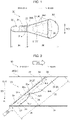
- FIG. 1 is a top view illustrating a cooling hole 30 in the film cooling structure 10 according to the present embodiment.
- FIG. 2 is a cross-sectional view illustrating a film cooling structure 10 according to the present embodiment.
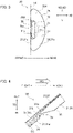
- FIG. 3 is a diagram illustrating the cooling hole 30 viewed from an outlet side of the cooling hole 30 along an extending direction ED of the cooling holes 30.
- a direction perpendicular to the extending direction ED of the cooling hole 30 and along a wall part 20 will be referred to as a width direction WD.
- a direction perpendicular to the extending direction ED and the width direction WD of the cooling hole 30 is referred to as a height direction HD.
- a length in the width direction WD is referred to as "width”.
- the length in the height direction HD is referred to as "height".
- the film cooling structure 10 includes a wall part 20 and a cooling hole (cooling channel) 30.
- the wall part 20 has an inner surface 21 and an outer surface 22, and extends forward and rearward.
- the outer surface 22 is exposed to the heating medium HG.
- the inner surface 21 faces a cooling medium CG which is applied by a predetermined pressure.
- the material of the wall part 20 may be a known heat-resistant alloy.
- the cooling hole 30 is a channel for the cooling medium CG, and has an inner peripheral surface 31 extending with a tubular shape.
- the cooling hole 30 includes an inlet 32 opening to the inner surface 21 of the wall part 20 and an outlet 33 opening to the outer surface 22 of the wall part 20. That is, the tubular inner peripheral surface 31 forms the inlet 32 that opens to the inner surface 21 and the outlet 33 that opens to the outer surface 22.
- the cooling hole 30 penetrates through the wall part 20, and is inclined such that the outlet 33 is positioned rearward of the inlet 32.
- the cooling holes 30 extend from the inner surface 21 to the outer surface 22 at an angle inclined toward a flow direction of the heat medium HG with respect to a thickness direction TD of the wall part 20.
- the cooling medium CG flows into the inlet 32 of the cooling hole 30 and flows out from the outlet 33 of the cooling hole 30.
- the cooling holes 30 include a straight-tube part 34, a throat 35, and a diffuser part 36.
- the straight-tube part 34 has the inlet 32 of the cooling hole 30.
- the straight-tube part 34 extends from the inlet 32 toward the diffuser part 36, and is connected (communicated) to the diffuser part 36 through the throat 35.
- the straight-tube part 34 has a channel cross section formed in an elliptical shape or a forward curved semicircular shape.
- the channel cross section of the straight-tube part 34 may be a polygon such as a triangle, a rectangle or the like. In any cases, the channel cross section of the straight-tube part 34 gradually changes to a flat shape along the wall part 20 such that it becomes close to a channel cross section (cross section) of the throat 35 as it approaches the throat 35 described later.
- the throat 35 is a flow path (constricted portion or narrowed portion) having a channel cross section 35A which is the minimum cross section of the cooling hole 30.
- the channel cross section 35A is flat along the wall part 20. That is, the width of the throat 35 is sufficiently larger than the height of the throat 35.
- the cross sectional area described herein is an area of a cross section orthogonal to the extending direction ED of the cooling hole 30.
- the width of the throat 35 may be equal to or greater than the width of the straight-tube part 34. In either case, the width of the throat 35 is equal to the minimum width of the diffuser part 36.
- the diffuser part 36 extends from the throat 35 to the outlet 33.
- the diffuser part 36 includes a channel cross section 36A.
- the channel cross section 36A expands rearward and along the wall part 20 (i.e., in the width direction WD) as it approaches the outlet 33.
- the channel cross section 36A is formed in a flat semicircular shape along the wall part 20.
- the diffuser part 36 has a flat surface 37 and a curved surface 38 both as an inner peripheral surface 31 forming a semicircular channel cross section 36A.
- the flat surface 37 is positioned forward of the curved surface 38 and extends in the width direction.
- the curved surface 38 is located rearward of the flat surface 37 and curved rearward.
- the flat surface 37 is a chord on an outer edge of the aforementioned semicircular cross section, and the curved surface 38 is an arc on the outer edge.
- this "chord” is not limited to a straight line as described later.
- the flat surface 37 and the curved surface 38 are integrally (continuously) formed via minute curved surfaces (i.e., fillets) for smoothly connecting between these two.
- the width of the channel cross section 36A of the diffuser part 36 increases as it approaches the outlet 33.
- the height of the channel cross section 36A also increases as it approaches the outlet 33.
- the height of the channel cross section 36A increases more rearward than forward as it approaches the outlet 33 based on the position of the channel cross section 35A of the throat 35 as viewed from the extending direction of the cooling hole 30.
- the inner peripheral surface 31 of the cooling hole 30 includes a flat portion 31a and a convex portion (first convex portion) 31b.
- the flat portion 31a is a flat surface formed in a belt-like shape extending in the width direction WD at a front part 31c of the inner peripheral surface 31.
- the flat portion 31a can have any length in the extending direction ED of the cooling hole 31 as long as the flat portion 31a at least faces the top of the convex portion 31b closest to the flat portion 31a.
- the convex portion 31b forms the throat 35 between the convex portion 31b and the flat portion 31a, the throat 35 having the channel cross section 35A with a minimum area.
- the convex portion 31b and the flat portion 31a constitute the throat 35 having the channel cross section 35A with a minimum area therebetween.
- the convex portion 31b protrudes from the rear part 31d of the inner peripheral surface 31 toward the flat portion 31a and extends in parallel with the flat portion 31a.
- the top of the convex portion 31b is separated from the flat portion 31a by a predetermined distance in the height direction HD to form the throat 35 as described above.
- the flat portion 31a and the convex portion 31b are provided at positions where the throat 35 is formed on the inner peripheral surface 31.
- the most forward portions e.g., the flat portion 31a in the throat 35
- the most forward portions are positioned at the same position (height, level) in the height direction HD as seen from the extending direction ED of the cooling hole 30.
- each of the straight-tube part 34, the throat 35, and the diffuser part 36 may be in contact with a virtual surface 50 extending in the extending direction ED and the width direction WD of the cooling hole 30 on their front side.
- FIG. 4 illustrates the flow of the cooling medium CG in the cooling hole 30.
- FIG. 4 shows the main stream of the cooling medium CG by solid lines.
- FIG. 5 is a diagram for explaining the velocity distribution of the flow of the cooling medium CG in the cooling hole 30.
- FIG. 5(a) is a diagram showing a schematic example of the velocity distribution in the throat 35.
- FIG. 5(b) is a diagram showing a schematic example of the velocity distribution in the diffuser part 36.
- the main stream of the cooling medium CG flows from the straight-tube part 34 toward the diffuser part 36.
- the convex portion 31b is provided on the upstream side (near the inlet 32) of the diffuser part 36 to form the throat 35.
- the convex portion 31b protrudes from the rear part 31d of the inner peripheral surface 31 toward the front part 31c of the inner peripheral surface 31. Accordingly, the convex portion 31b deflects the main stream of the cooling medium CG forward (i.e., toward the front part 31c or the flat portion 31a).
- the convex portion 31b forms the throat 35 together with the flat portion 31a of the inner peripheral surface 31.
- the area of the cross section of the cooling hole 30 is minimized at the throat 35.
- the channel cross section 35A of the throat 35 has a flat shape along the width direction WD. Therefore, the main stream of the cooling medium CG is accelerated while being compressed toward the throat 35.
- the flow of the cooling medium CG flows to the outlet 33 in a forward biased state.
- the flow path of the cooling hole 30 is expanded in the width direction WD in the diffuser part 36. Therefore, the main stream of the cooling medium CG expands in the width direction in a state where it is unevenly distributed forward, and flows out from the outlet 33.
- the main stream of the cooling medium CG is accelerated while being compressed forward. This reduces the velocity difference between the accelerated cooling medium CG and the main stream of the heat medium HG. Concequently, it is possible to suppress an aerodynamic loss (pressure loss) caused by mixing of the cooling medium CG and the heating medium HG when the cooling medium CG flows out of the outlet 33 of the cooling hole 30.
- the main stream of the cooling medium CG is expanded (dispersed) in the width direction WD by the diffuser part 36. Therefore, the film cooling can be widely performed with suppressing the aerodynamic loss. That is, the cooling efficiency with the cooling medium CG can be improved.
- a front surface (the front part 31c, e.g., the flat surface 37) of the inner peripheral surface 31 of the cooling hole 30 in the diffuser part 36 may include a convex portion (second convex portion) 39.
- the convex portion 39 projects rearward and extends to the outlet 33.
- the width of the convex portion 39 may be constant along the extending direction ED or may increase as it approaches the outlet 33.
- the convex portion 39 includes a top 39a projecting rearmost. As shown in FIG. 3 , the top 39a may be located at the center of the diffuser part 36 in the width direction WD.
- the convex portion 39 partially blocks the throat 35 when viewed from the extending direction ED of the cooling hole 30. Accordingly, the convex portion 39 promotes the widthwise expansion of the main stream, which is unevenly distributed forward, of the cooling medium CG by the diffuser part 36. With the promotion of the expansion, the area of film cooling can be enlarged in the width direction WD.
- FIG. 6 is a perspective view illustrating a schematic configuration of the turbine blade (stator vane 60).
- the stator vane 60 together with a rotor blade (not shown) constitute a turbine (not shown) of a gas turbine engine (not shown).
- the film cooling structure 10 can also be applied to the rotor blade (not shown) which is the turbine blade constituting the turbine (not shown).
- FIG. 6 is a perspective view illustrating a schematic configuration of the stator vane 60.
- the stator vane 60 includes an airfoil 61, bands 62, and cooling holes 30.
- the airfoil 61 is provided on the downstream side of a combustor (not shown) which discharges the combustion gas as the aforementioned heating medium HG. That is, the airfoil 61 is located in a flow path of the combustion gas.
- the airfoil 61 has a leading edge 61a, a trailing edge 61b, a pressure surface (pressure side) 61c, and a suction surface (suction side) 61d. Combustion gas as the heating medium HG flows in the direction from the leading edge 61a to the trailing edge 61b along the pressure surface 61c and the suction surface 61d.
- the airfoil 61 is provided with an internal space (cavity or cooling channel (not shown)) into which cooling air as a cooling medium CG is introduced.
- the cooling air is extracted from a compressor (not shown), for example.
- the bands 62 are provided to sandwich the airfoil 61 in a span direction SD of the airfoil 61.
- the bands 62 function as a part of a wall of the flow path of the combustion gas (i.e., endwalls, platforms or shrouds). These bands 62 are integrated with the tip and the hub of the airfoil 61.
- the film cooling structure 10 is applied to at least one of the pressure surface 61c and the suction surface 61d of the airfoil 61. That is, at least one of the pressure surface 61c and the suction surface 61d of the airfoil 61 functions as the wall part 20 of the film cooling structure 10, and the cooling holes 30 are formed therein.
- the film cooling structure 10 is provided on the pressure surface 61c.
- the cooling hole 30 is formed on the pressure surface 61c.
- the cooling hole 30 is inclined such that the outlet 33 is positioned closer to the trailing edge 61b than the inlet 32.
- the flat surface 37 of the diffuser part 36 extends in the extending direction ED of the cooling hole 30 and in the span direction SD of the airfoil 61.
- the cooling air which has been introduced into the airfoil 61, flows into the inlet 32 of the cooling hole 30 and flows out of the outlet 33.
- the cooling air which has flown out of the outlet 33, flows downstream while merging with the main stream of the combustion gas. While exiting the outlet 33, the cooling air is expanded in the span direction SD. Therefore, the cooling area on the pressure surface 61c can be extended in the span direction SD.
- the cooling air is accelerated until it flows out of the outlet 33.
- the speed difference between the main stream of the cooling air and the main stream of the combustion gas is reduced, thereby aerodynamic loss can be suppressed. That is, it is possible to provide a turbine blade capable of performing film cooling of a wide area while suppressing aerodynamic loss.
Landscapes
- Engineering & Computer Science (AREA)
- Mechanical Engineering (AREA)
- General Engineering & Computer Science (AREA)
- Turbine Rotor Nozzle Sealing (AREA)
Abstract
Description
- The present disclosure relates to a film cooling structure and a turbine blade for a gas turbine engine.
- A turbine of a gas turbine engine includes turbine blades that constitute stator vanes and turbine blades. The turbine blades are exposed to combustion gas from the combustor. To prevent thermal damage due to the combustion gas, a number of film cooling holes are formed on an airfoil surface of each turbine blade (see Patent Literatures 1 and 2).
-
- Patent Literature 1:
Japanese Patent No. 5600449 - Patent Literature 2:
Japanese Patent Laid-Open Application Publication No. 2013-124612 - To improve the efficiency of the gas turbine engine, it is important to increase the temperature of combustion gas (combustion temperature). With the increase of combustion temperature, further improvement is required in the cooling efficiency of the turbine blade.
- The present disclosure has been made with the above consideration, is objected to provide a film cooling structure and a turbine blade for a gas turbine engine, which are capable of improving cooling efficiency.
- A first aspect of the present disclosure is a film cooling structure including: a wall part having an outer surface and an inner surface and extending forward and rearward; and a cooling hole including an inner peripheral surface formed in a tubular shape, the inner peripheral surface forming an inlet opening to the inner surface and an outlet opening to the outer surface, the cooling hole penetrating through the wall part and being inclined such that the outlet is positioned rearward of the inlet; wherein the cooling hole includes: a throat having a minimum cross section; and a diffuser part extending from the throat to the outlet and including a channel cross section expanding rearward and along the wall part as the channel cross section approaches the outlet, and the inner peripheral surface of the cooling hole includes: a flat portion at a front part of the inner peripheral surface, extending in a direction which is perpendicular to an extending direction of the cooling hole and is along the wall part; and a convex portion projecting from a rear part of the inner peripheral surface toward the flat portion, extending in parallel with the flat portion, and forming the throat between the convex portion and the flat portion.
- A front surface of the inner peripheral surface of the cooling hole in the diffuser part may include a convex portion projecting rearward and extending to the outlet.
- A second aspect of the present disclosure is a turbine blade for a gas turbine engine including the film cooling structure according to the first aspect of the present disclosure.
- The present disclosure can provide a film cooling structure and a turbine blade for a gas turbine engine, which are capable of improving cooling efficiency.
-
-
FIG. 1 is a top view illustrating a cooling hole according to an embodiment of the present disclosure. -
FIG. 2 is a cross-sectional view illustrating a film cooling structure according to an embodiment of the present disclosure. -
FIG. 3 is a diagram illustrating the cooling hole viewed from an outlet side of the cooling hole along an extending direction of the cooling hole. -
FIG. 4 is a diagram illustrating a flow of the cooling medium through the cooling hole. -
FIGs. 5(a) and 5(b) are diagrams for explaining the velocity distribution of the flow of the cooling medium in the cooling hole,FIG. 5(a) is a diagram showing a schematic example of the velocity distribution at the throat, andFIG. 5(b) is a diagram showing a schematic example of the velocity distribution in the diffuser part. -
FIG. 6 is a perspective view showing a schematic configuration of a turbine blade (stationary blade) according to an embodiment of the present disclosure. - Embodiments of the present disclosure will be described with reference to the drawings. Components common in respective drawings are denoted by the same reference numerals, and the description to be duplicated thereof will be omitted.
- The film cooling structure according to the present embodiment is provided on a structure exposed to a high-temperature heat medium (for example, combustion gas). The structure may be, for example, a turbine blade (rotor blade and stator vane) of a gas turbine engine (not shown), a combustor liner, a nozzle of a rocket engine, or the like. A large number of cooling holes are formed in a wall part of the structure. The cooling holes constitute a film cooling structure together with the wall part. The cooling medium CG (e.g., air) flowing out of the cooling holes forms a heat insulating layer on the wall part to protect the structure from the heat medium. Hereinafter, for convenience of explanation, the upstream side in the flow direction of the heat medium HG is defined as "forward (front)" and the downstream side in the flow direction of the heat medium HG is defined as "rearward (rear)".
-
FIG. 1 is a top view illustrating acooling hole 30 in thefilm cooling structure 10 according to the present embodiment.FIG. 2 is a cross-sectional view illustrating afilm cooling structure 10 according to the present embodiment.FIG. 3 is a diagram illustrating thecooling hole 30 viewed from an outlet side of thecooling hole 30 along an extending direction ED of thecooling holes 30. For convenience of explanation, a direction perpendicular to the extending direction ED of thecooling hole 30 and along awall part 20 will be referred to as a width direction WD. A direction perpendicular to the extending direction ED and the width direction WD of thecooling hole 30 is referred to as a height direction HD. Further, A length in the width direction WD is referred to as "width". The length in the height direction HD is referred to as "height". - As shown in
FIG. 2 , thefilm cooling structure 10 includes awall part 20 and a cooling hole (cooling channel) 30. Thewall part 20 has aninner surface 21 and anouter surface 22, and extends forward and rearward. Theouter surface 22 is exposed to the heating medium HG. On the other hand, theinner surface 21 faces a cooling medium CG which is applied by a predetermined pressure. The material of thewall part 20 may be a known heat-resistant alloy. - The
cooling hole 30 is a channel for the cooling medium CG, and has an innerperipheral surface 31 extending with a tubular shape. Thecooling hole 30 includes aninlet 32 opening to theinner surface 21 of thewall part 20 and anoutlet 33 opening to theouter surface 22 of thewall part 20. That is, the tubular innerperipheral surface 31 forms theinlet 32 that opens to theinner surface 21 and theoutlet 33 that opens to theouter surface 22. - The
cooling hole 30 penetrates through thewall part 20, and is inclined such that theoutlet 33 is positioned rearward of theinlet 32. In other words, thecooling holes 30 extend from theinner surface 21 to theouter surface 22 at an angle inclined toward a flow direction of the heat medium HG with respect to a thickness direction TD of thewall part 20. The cooling medium CG flows into theinlet 32 of thecooling hole 30 and flows out from theoutlet 33 of thecooling hole 30. - As shown in
FIGs. 1 and 2 , thecooling holes 30 include a straight-tube part 34, athroat 35, and adiffuser part 36. The straight-tube part 34 has theinlet 32 of thecooling hole 30. The straight-tube part 34 extends from theinlet 32 toward thediffuser part 36, and is connected (communicated) to thediffuser part 36 through thethroat 35. The straight-tube part 34 has a channel cross section formed in an elliptical shape or a forward curved semicircular shape. The channel cross section of the straight-tube part 34 may be a polygon such as a triangle, a rectangle or the like. In any cases, the channel cross section of the straight-tube part 34 gradually changes to a flat shape along thewall part 20 such that it becomes close to a channel cross section (cross section) of thethroat 35 as it approaches thethroat 35 described later. - The
throat 35 is a flow path (constricted portion or narrowed portion) having achannel cross section 35A which is the minimum cross section of thecooling hole 30. Thechannel cross section 35A is flat along thewall part 20. That is, the width of thethroat 35 is sufficiently larger than the height of thethroat 35. The cross sectional area described herein is an area of a cross section orthogonal to the extending direction ED of thecooling hole 30. The width of thethroat 35 may be equal to or greater than the width of the straight-tube part 34. In either case, the width of thethroat 35 is equal to the minimum width of thediffuser part 36. - The
diffuser part 36 extends from thethroat 35 to theoutlet 33. Thediffuser part 36 includes achannel cross section 36A. Thechannel cross section 36A expands rearward and along the wall part 20 (i.e., in the width direction WD) as it approaches theoutlet 33. For example, as shown inFIG. 3 , thechannel cross section 36A is formed in a flat semicircular shape along thewall part 20. In this case, thediffuser part 36 has a flat surface 37 and a curved surface 38 both as an innerperipheral surface 31 forming a semicircularchannel cross section 36A. The flat surface 37 is positioned forward of the curved surface 38 and extends in the width direction. On the other hand, the curved surface 38 is located rearward of the flat surface 37 and curved rearward. That is, the flat surface 37 is a chord on an outer edge of the aforementioned semicircular cross section, and the curved surface 38 is an arc on the outer edge. However, as described later, this "chord" is not limited to a straight line as described later. Note that the flat surface 37 and the curved surface 38 are integrally (continuously) formed via minute curved surfaces (i.e., fillets) for smoothly connecting between these two. - As shown in
FIGs. 1 and3 , the width of thechannel cross section 36A of thediffuser part 36 increases as it approaches theoutlet 33. As shown inFIG. 3 , the height of thechannel cross section 36A also increases as it approaches theoutlet 33. However, the height of thechannel cross section 36A increases more rearward than forward as it approaches theoutlet 33 based on the position of thechannel cross section 35A of thethroat 35 as viewed from the extending direction of thecooling hole 30. - As shown in
FIGs. 2 and3 , the innerperipheral surface 31 of thecooling hole 30 includes aflat portion 31a and a convex portion (first convex portion) 31b. Theflat portion 31a is a flat surface formed in a belt-like shape extending in the width direction WD at afront part 31c of the innerperipheral surface 31. Theflat portion 31a can have any length in the extending direction ED of thecooling hole 31 as long as theflat portion 31a at least faces the top of theconvex portion 31b closest to theflat portion 31a. - The
convex portion 31b forms thethroat 35 between theconvex portion 31b and theflat portion 31a, thethroat 35 having thechannel cross section 35A with a minimum area. In other words, theconvex portion 31b and theflat portion 31a constitute thethroat 35 having thechannel cross section 35A with a minimum area therebetween. Theconvex portion 31b protrudes from therear part 31d of the innerperipheral surface 31 toward theflat portion 31a and extends in parallel with theflat portion 31a. The top of theconvex portion 31b is separated from theflat portion 31a by a predetermined distance in the height direction HD to form thethroat 35 as described above. In other words, theflat portion 31a and theconvex portion 31b are provided at positions where thethroat 35 is formed on the innerperipheral surface 31. - As shown in
FIG. 3 , of the innerperipheral surface 31 in the straight-tube part 34, thethroat 35, and thediffuser part 36, the most forward portions (e.g., theflat portion 31a in the throat 35) are positioned at the same position (height, level) in the height direction HD as seen from the extending direction ED of thecooling hole 30. For example, each of the straight-tube part 34, thethroat 35, and thediffuser part 36 may be in contact with avirtual surface 50 extending in the extending direction ED and the width direction WD of thecooling hole 30 on their front side. -
FIG. 4 illustrates the flow of the cooling medium CG in thecooling hole 30.FIG. 4 shows the main stream of the cooling medium CG by solid lines.FIG. 5 is a diagram for explaining the velocity distribution of the flow of the cooling medium CG in thecooling hole 30.FIG. 5(a) is a diagram showing a schematic example of the velocity distribution in thethroat 35.FIG. 5(b) is a diagram showing a schematic example of the velocity distribution in thediffuser part 36. - As shown in
FIG. 4 , the main stream of the cooling medium CG flows from the straight-tube part 34 toward thediffuser part 36. Here, it should be noted that theconvex portion 31b is provided on the upstream side (near the inlet 32) of thediffuser part 36 to form thethroat 35. As described above, theconvex portion 31b protrudes from therear part 31d of the innerperipheral surface 31 toward thefront part 31c of the innerperipheral surface 31. Accordingly, theconvex portion 31b deflects the main stream of the cooling medium CG forward (i.e., toward thefront part 31c or theflat portion 31a). - The
convex portion 31b forms thethroat 35 together with theflat portion 31a of the innerperipheral surface 31. The area of the cross section of thecooling hole 30 is minimized at thethroat 35. Thechannel cross section 35A of thethroat 35 has a flat shape along the width direction WD. Therefore, the main stream of the cooling medium CG is accelerated while being compressed toward thethroat 35. - Even after passing through the
throat 35, the flow of the cooling medium CG flows to theoutlet 33 in a forward biased state. On the other hand, the flow path of thecooling hole 30 is expanded in the width direction WD in thediffuser part 36. Therefore, the main stream of the cooling medium CG expands in the width direction in a state where it is unevenly distributed forward, and flows out from theoutlet 33. - As described above, the main stream of the cooling medium CG is accelerated while being compressed forward. This reduces the velocity difference between the accelerated cooling medium CG and the main stream of the heat medium HG. Concequently,
it is possible to suppress an aerodynamic loss (pressure loss) caused by mixing of the cooling medium CG and the heating medium HG when the cooling medium CG flows out of theoutlet 33 of thecooling hole 30. - The main stream of the cooling medium CG is expanded (dispersed) in the width direction WD by the
diffuser part 36. Therefore, the film cooling can be widely performed with suppressing the aerodynamic loss. That is, the cooling efficiency with the cooling medium CG can be improved. - As shown by dotted lines in
FIGs. 1 to 3 , a front surface (thefront part 31c, e.g., the flat surface 37) of the innerperipheral surface 31 of thecooling hole 30 in thediffuser part 36 may include a convex portion (second convex portion) 39. Theconvex portion 39 projects rearward and extends to theoutlet 33. The width of theconvex portion 39 may be constant along the extending direction ED or may increase as it approaches theoutlet 33. Theconvex portion 39 includes a top 39a projecting rearmost. As shown inFIG. 3 , the top 39a may be located at the center of thediffuser part 36 in the width direction WD. In any cases, theconvex portion 39 partially blocks thethroat 35 when viewed from the extending direction ED of thecooling hole 30. Accordingly, theconvex portion 39 promotes the widthwise expansion of the main stream, which is unevenly distributed forward, of the cooling medium CG by thediffuser part 36. With the promotion of the expansion, the area of film cooling can be enlarged in the width direction WD. - The
film cooling structure 10 according to the present embodiment can be applied to a turbine blade for a gas turbine engine.FIG. 6 is a perspective view illustrating a schematic configuration of the turbine blade (stator vane 60). Thestator vane 60 together with a rotor blade (not shown) constitute a turbine (not shown) of a gas turbine engine (not shown). Thefilm cooling structure 10 can also be applied to the rotor blade (not shown) which is the turbine blade constituting the turbine (not shown). -
FIG. 6 is a perspective view illustrating a schematic configuration of thestator vane 60. As shown in this figure, thestator vane 60 includes anairfoil 61,bands 62, and cooling holes 30. Theairfoil 61 is provided on the downstream side of a combustor (not shown) which discharges the combustion gas as the aforementioned heating medium HG. That is, theairfoil 61 is located in a flow path of the combustion gas. - The
airfoil 61 has aleading edge 61a, a trailingedge 61b, a pressure surface (pressure side) 61c, and a suction surface (suction side) 61d. Combustion gas as the heating medium HG flows in the direction from theleading edge 61a to the trailingedge 61b along thepressure surface 61c and thesuction surface 61d. - The
airfoil 61 is provided with an internal space (cavity or cooling channel (not shown)) into which cooling air as a cooling medium CG is introduced. The cooling air is extracted from a compressor (not shown), for example. Thebands 62 are provided to sandwich theairfoil 61 in a span direction SD of theairfoil 61. Thebands 62 function as a part of a wall of the flow path of the combustion gas (i.e., endwalls, platforms or shrouds). Thesebands 62 are integrated with the tip and the hub of theairfoil 61. - In this embodiment, the
film cooling structure 10 is applied to at least one of thepressure surface 61c and thesuction surface 61d of theairfoil 61. That is, at least one of thepressure surface 61c and thesuction surface 61d of theairfoil 61 functions as thewall part 20 of thefilm cooling structure 10, and the cooling holes 30 are formed therein. Hereinafter, for convenience of explanation, an example in which thefilm cooling structure 10 is provided on thepressure surface 61c will be described. - The
cooling hole 30 is formed on thepressure surface 61c. Thecooling hole 30 is inclined such that theoutlet 33 is positioned closer to the trailingedge 61b than theinlet 32. The flat surface 37 of thediffuser part 36 extends in the extending direction ED of thecooling hole 30 and in the span direction SD of theairfoil 61. - In the
pressure surface 61c, the main stream of the combustion gas flows in a direction from theleading edge 61a toward the trailingedge 61b. On the other hand, the cooling air, which has been introduced into theairfoil 61, flows into theinlet 32 of thecooling hole 30 and flows out of theoutlet 33. The cooling air, which has flown out of theoutlet 33, flows downstream while merging with the main stream of the combustion gas. While exiting theoutlet 33, the cooling air is expanded in the span direction SD. Therefore, the cooling area on thepressure surface 61c can be extended in the span direction SD. - In addition, the cooling air is accelerated until it flows out of the
outlet 33. Thus, the speed difference between the main stream of the cooling air and the main stream of the combustion gas is reduced, thereby aerodynamic loss can be suppressed. That is, it is possible to provide a turbine blade capable of performing film cooling of a wide area while suppressing aerodynamic loss. - It should be noted that the present disclosure is not limited to the embodiments described above, but is indicated by the description of the claims and further includes all modifications within the meaning and scope of the description of the claims.
Claims (3)
- A film cooling structure comprising:a wall part having an outer surface and an inner surface and extending forward and rearward; anda cooling hole including an inner peripheral surface formed in a tubular shape, the inner peripheral surface forming an inlet opening to the inner surface and an outlet opening to the outer surface, the cooling hole penetrating through the wall part and being inclined such that the outlet is positioned rearward of the inlet; whereinthe cooling hole includes:a throat having a minimum cross section; anda diffuser part extending from the throat to the outlet and including a channel cross section expanding rearward and along the wall part as the channel cross section approaches the outlet, andthe inner peripheral surface of the cooling hole includes:a flat portion at a front part of the inner peripheral surface, extending in a direction which is perpendicular to an extending direction of the cooling hole and is along the wall part; anda convex portion projecting from a rear part of the inner peripheral surface toward the flat portion, extending in parallel with the flat portion, and forming the throat between the convex portion and the flat portion.
- The film cooling structure according to claim 1, wherein
a front surface of the inner peripheral surface of the cooling hole in the diffuser part includes a convex portion projecting rearward and extending to the outlet. - A turbine blade for a gas turbine engine comprising the film cooling structure according to claim 1 or 2.
Applications Claiming Priority (2)
| Application Number | Priority Date | Filing Date | Title |
|---|---|---|---|
| JP2019107005 | 2019-06-07 | ||
| PCT/JP2020/020550 WO2020246289A1 (en) | 2019-06-07 | 2020-05-25 | Film cooling structure, and turbine blade for gas turbine engine |
Publications (3)
| Publication Number | Publication Date |
|---|---|
| EP3981953A1 true EP3981953A1 (en) | 2022-04-13 |
| EP3981953A4 EP3981953A4 (en) | 2022-11-30 |
| EP3981953B1 EP3981953B1 (en) | 2024-08-21 |
Family
ID=73652852
Family Applications (1)
| Application Number | Title | Priority Date | Filing Date |
|---|---|---|---|
| EP20819223.7A Active EP3981953B1 (en) | 2019-06-07 | 2020-05-25 | Film cooling structure and turbine blade for gas turbine engine |
Country Status (4)
| Country | Link |
|---|---|
| US (1) | US11732591B2 (en) |
| EP (1) | EP3981953B1 (en) |
| JP (1) | JP7248112B2 (en) |
| WO (1) | WO2020246289A1 (en) |
Families Citing this family (2)
| Publication number | Priority date | Publication date | Assignee | Title |
|---|---|---|---|---|
| CN114263933B (en) * | 2022-03-02 | 2022-07-08 | 成都中科翼能科技有限公司 | Combined type multi-channel diffuser of gas turbine and diffusion air inlet structure thereof |
| KR20250179885A (en) * | 2024-06-24 | 2025-12-31 | 두산에너빌리티 주식회사 | Airfoil for turbine and gas turbnie including the same |
Family Cites Families (11)
| Publication number | Priority date | Publication date | Assignee | Title |
|---|---|---|---|---|
| GB1296424A (en) | 1970-08-18 | 1972-11-15 | ||
| GB2389330B (en) * | 2003-03-31 | 2004-05-05 | M J Technologies Ltd | Machining of cooling air holes in gas turbine components |
| US7374401B2 (en) | 2005-03-01 | 2008-05-20 | General Electric Company | Bell-shaped fan cooling holes for turbine airfoil |
| US8052378B2 (en) | 2009-03-18 | 2011-11-08 | General Electric Company | Film-cooling augmentation device and turbine airfoil incorporating the same |
| JP6019578B2 (en) | 2011-12-15 | 2016-11-02 | 株式会社Ihi | Turbine blade |
| JP5982807B2 (en) * | 2011-12-15 | 2016-08-31 | 株式会社Ihi | Turbine blade |
| US9279330B2 (en) * | 2012-02-15 | 2016-03-08 | United Technologies Corporation | Gas turbine engine component with converging/diverging cooling passage |
| CN105189976B (en) * | 2013-03-15 | 2019-04-16 | 联合工艺公司 | Additive Manufacturing Method for Additional Features in Cooling Holes |
| US20160201474A1 (en) * | 2014-10-17 | 2016-07-14 | United Technologies Corporation | Gas turbine engine component with film cooling hole feature |
| US10760431B2 (en) * | 2017-09-07 | 2020-09-01 | General Electric Company | Component for a turbine engine with a cooling hole |
| US20190071977A1 (en) * | 2017-09-07 | 2019-03-07 | General Electric Company | Component for a turbine engine with a cooling hole |
-
2020
- 2020-05-25 EP EP20819223.7A patent/EP3981953B1/en active Active
- 2020-05-25 JP JP2021524767A patent/JP7248112B2/en active Active
- 2020-05-25 WO PCT/JP2020/020550 patent/WO2020246289A1/en not_active Ceased
-
2021
- 2021-09-29 US US17/449,316 patent/US11732591B2/en active Active
Also Published As
| Publication number | Publication date |
|---|---|
| EP3981953A4 (en) | 2022-11-30 |
| JP7248112B2 (en) | 2023-03-29 |
| WO2020246289A1 (en) | 2020-12-10 |
| US11732591B2 (en) | 2023-08-22 |
| JPWO2020246289A1 (en) | 2020-12-10 |
| US20220018261A1 (en) | 2022-01-20 |
| EP3981953B1 (en) | 2024-08-21 |
Similar Documents
| Publication | Publication Date | Title |
|---|---|---|
| JP4941891B2 (en) | Film cooling structure | |
| US11708762B2 (en) | Film cooling structure and turbine blade for gas turbine engine | |
| CN107429568B (en) | Internal cooling system with converging-diverging outlet slots in trailing-edge cooling passages for airfoils in turbine engines | |
| US8668453B2 (en) | Cooling system having reduced mass pin fins for components in a gas turbine engine | |
| US8523523B2 (en) | Cooling arrangements | |
| US8066484B1 (en) | Film cooling hole for a turbine airfoil | |
| JP5442190B2 (en) | Similar tip baffle airfoil | |
| JP4184323B2 (en) | Hollow rotor blades for gas turbine engine turbines | |
| US8079813B2 (en) | Turbine blade with multiple trailing edge cooling slots | |
| US20100068032A1 (en) | Turbine Airfoil Cooling System with Diffusion Film Cooling Hole | |
| US20110038709A1 (en) | Turbine Vane for a Gas Turbine Engine Having Serpentine Cooling Channels | |
| CN107131006B (en) | Turbine blade | |
| CN106661944A (en) | End wall configuration for gas turbine engine | |
| JP2007514888A (en) | Cooling turbine vane platform | |
| WO2018182816A1 (en) | Turbine airfoil with thin trailing edge cooling circuit | |
| JP2017082771A (en) | Turbine blade | |
| JP2006105152A (en) | Turbine airfoil at stepped exit | |
| EP1484476A2 (en) | Cooled platform for a turbine nozzle guide vane or rotor blade | |
| JP2017078414A (en) | Turbine blade | |
| US11732591B2 (en) | Film cooling structure and turbine blade for gas turbine engine | |
| CN107407150A (en) | The turbo blade of guide structure is turned to non-binding flowing | |
| CN104884741A (en) | Blade for a turbomachine | |
| CN117083447A (en) | Wall provided with cooling holes including a diffusion portion having a triangular cross-section | |
| JP2012052513A (en) | Turbine blade |
Legal Events
| Date | Code | Title | Description |
|---|---|---|---|
| STAA | Information on the status of an ep patent application or granted ep patent |
Free format text: STATUS: THE INTERNATIONAL PUBLICATION HAS BEEN MADE |
|
| PUAI | Public reference made under article 153(3) epc to a published international application that has entered the european phase |
Free format text: ORIGINAL CODE: 0009012 |
|
| STAA | Information on the status of an ep patent application or granted ep patent |
Free format text: STATUS: REQUEST FOR EXAMINATION WAS MADE |
|
| 17P | Request for examination filed |
Effective date: 20220107 |
|
| AK | Designated contracting states |
Kind code of ref document: A1 Designated state(s): AL AT BE BG CH CY CZ DE DK EE ES FI FR GB GR HR HU IE IS IT LI LT LU LV MC MK MT NL NO PL PT RO RS SE SI SK SM TR |
|
| DAV | Request for validation of the european patent (deleted) | ||
| DAX | Request for extension of the european patent (deleted) | ||
| A4 | Supplementary search report drawn up and despatched |
Effective date: 20221031 |
|
| RIC1 | Information provided on ipc code assigned before grant |
Ipc: F01D 9/06 20060101ALI20221025BHEP Ipc: F01D 5/18 20060101AFI20221025BHEP |
|
| GRAP | Despatch of communication of intention to grant a patent |
Free format text: ORIGINAL CODE: EPIDOSNIGR1 |
|
| STAA | Information on the status of an ep patent application or granted ep patent |
Free format text: STATUS: GRANT OF PATENT IS INTENDED |
|
| INTG | Intention to grant announced |
Effective date: 20231213 |
|
| GRAJ | Information related to disapproval of communication of intention to grant by the applicant or resumption of examination proceedings by the epo deleted |
Free format text: ORIGINAL CODE: EPIDOSDIGR1 |
|
| STAA | Information on the status of an ep patent application or granted ep patent |
Free format text: STATUS: REQUEST FOR EXAMINATION WAS MADE |
|
| GRAP | Despatch of communication of intention to grant a patent |
Free format text: ORIGINAL CODE: EPIDOSNIGR1 |
|
| STAA | Information on the status of an ep patent application or granted ep patent |
Free format text: STATUS: GRANT OF PATENT IS INTENDED |
|
| INTC | Intention to grant announced (deleted) | ||
| INTG | Intention to grant announced |
Effective date: 20240419 |
|
| GRAS | Grant fee paid |
Free format text: ORIGINAL CODE: EPIDOSNIGR3 |
|
| GRAA | (expected) grant |
Free format text: ORIGINAL CODE: 0009210 |
|
| STAA | Information on the status of an ep patent application or granted ep patent |
Free format text: STATUS: THE PATENT HAS BEEN GRANTED |
|
| AK | Designated contracting states |
Kind code of ref document: B1 Designated state(s): AL AT BE BG CH CY CZ DE DK EE ES FI FR GB GR HR HU IE IS IT LI LT LU LV MC MK MT NL NO PL PT RO RS SE SI SK SM TR |
|
| REG | Reference to a national code |
Ref country code: GB Ref legal event code: FG4D |
|
| REG | Reference to a national code |
Ref country code: CH Ref legal event code: EP |
|
| REG | Reference to a national code |
Ref country code: IE Ref legal event code: FG4D |
|
| REG | Reference to a national code |
Ref country code: DE Ref legal event code: R096 Ref document number: 602020036349 Country of ref document: DE |
|
| REG | Reference to a national code |
Ref country code: LT Ref legal event code: MG9D |
|
| REG | Reference to a national code |
Ref country code: NL Ref legal event code: MP Effective date: 20240821 |
|
| PG25 | Lapsed in a contracting state [announced via postgrant information from national office to epo] |
Ref country code: NO Free format text: LAPSE BECAUSE OF FAILURE TO SUBMIT A TRANSLATION OF THE DESCRIPTION OR TO PAY THE FEE WITHIN THE PRESCRIBED TIME-LIMIT Effective date: 20241121 |
|
| REG | Reference to a national code |
Ref country code: AT Ref legal event code: MK05 Ref document number: 1715658 Country of ref document: AT Kind code of ref document: T Effective date: 20240821 |
|
| PG25 | Lapsed in a contracting state [announced via postgrant information from national office to epo] |
Ref country code: FI Free format text: LAPSE BECAUSE OF FAILURE TO SUBMIT A TRANSLATION OF THE DESCRIPTION OR TO PAY THE FEE WITHIN THE PRESCRIBED TIME-LIMIT Effective date: 20240821 Ref country code: NL Free format text: LAPSE BECAUSE OF FAILURE TO SUBMIT A TRANSLATION OF THE DESCRIPTION OR TO PAY THE FEE WITHIN THE PRESCRIBED TIME-LIMIT Effective date: 20240821 Ref country code: GR Free format text: LAPSE BECAUSE OF FAILURE TO SUBMIT A TRANSLATION OF THE DESCRIPTION OR TO PAY THE FEE WITHIN THE PRESCRIBED TIME-LIMIT Effective date: 20241122 Ref country code: PL Free format text: LAPSE BECAUSE OF FAILURE TO SUBMIT A TRANSLATION OF THE DESCRIPTION OR TO PAY THE FEE WITHIN THE PRESCRIBED TIME-LIMIT Effective date: 20240821 Ref country code: PT Free format text: LAPSE BECAUSE OF FAILURE TO SUBMIT A TRANSLATION OF THE DESCRIPTION OR TO PAY THE FEE WITHIN THE PRESCRIBED TIME-LIMIT Effective date: 20241223 |
|
| PG25 | Lapsed in a contracting state [announced via postgrant information from national office to epo] |
Ref country code: BG Free format text: LAPSE BECAUSE OF FAILURE TO SUBMIT A TRANSLATION OF THE DESCRIPTION OR TO PAY THE FEE WITHIN THE PRESCRIBED TIME-LIMIT Effective date: 20240821 |
|
| PG25 | Lapsed in a contracting state [announced via postgrant information from national office to epo] |
Ref country code: LV Free format text: LAPSE BECAUSE OF FAILURE TO SUBMIT A TRANSLATION OF THE DESCRIPTION OR TO PAY THE FEE WITHIN THE PRESCRIBED TIME-LIMIT Effective date: 20240821 |
|
| PG25 | Lapsed in a contracting state [announced via postgrant information from national office to epo] |
Ref country code: IS Free format text: LAPSE BECAUSE OF FAILURE TO SUBMIT A TRANSLATION OF THE DESCRIPTION OR TO PAY THE FEE WITHIN THE PRESCRIBED TIME-LIMIT Effective date: 20241221 Ref country code: AT Free format text: LAPSE BECAUSE OF FAILURE TO SUBMIT A TRANSLATION OF THE DESCRIPTION OR TO PAY THE FEE WITHIN THE PRESCRIBED TIME-LIMIT Effective date: 20240821 |
|
| PG25 | Lapsed in a contracting state [announced via postgrant information from national office to epo] |
Ref country code: HR Free format text: LAPSE BECAUSE OF FAILURE TO SUBMIT A TRANSLATION OF THE DESCRIPTION OR TO PAY THE FEE WITHIN THE PRESCRIBED TIME-LIMIT Effective date: 20240821 |
|
| PG25 | Lapsed in a contracting state [announced via postgrant information from national office to epo] |
Ref country code: RS Free format text: LAPSE BECAUSE OF FAILURE TO SUBMIT A TRANSLATION OF THE DESCRIPTION OR TO PAY THE FEE WITHIN THE PRESCRIBED TIME-LIMIT Effective date: 20241121 Ref country code: ES Free format text: LAPSE BECAUSE OF FAILURE TO SUBMIT A TRANSLATION OF THE DESCRIPTION OR TO PAY THE FEE WITHIN THE PRESCRIBED TIME-LIMIT Effective date: 20240821 |
|
| PG25 | Lapsed in a contracting state [announced via postgrant information from national office to epo] |
Ref country code: RS Free format text: LAPSE BECAUSE OF FAILURE TO SUBMIT A TRANSLATION OF THE DESCRIPTION OR TO PAY THE FEE WITHIN THE PRESCRIBED TIME-LIMIT Effective date: 20241121 Ref country code: PT Free format text: LAPSE BECAUSE OF FAILURE TO SUBMIT A TRANSLATION OF THE DESCRIPTION OR TO PAY THE FEE WITHIN THE PRESCRIBED TIME-LIMIT Effective date: 20241223 Ref country code: PL Free format text: LAPSE BECAUSE OF FAILURE TO SUBMIT A TRANSLATION OF THE DESCRIPTION OR TO PAY THE FEE WITHIN THE PRESCRIBED TIME-LIMIT Effective date: 20240821 Ref country code: NO Free format text: LAPSE BECAUSE OF FAILURE TO SUBMIT A TRANSLATION OF THE DESCRIPTION OR TO PAY THE FEE WITHIN THE PRESCRIBED TIME-LIMIT Effective date: 20241121 Ref country code: NL Free format text: LAPSE BECAUSE OF FAILURE TO SUBMIT A TRANSLATION OF THE DESCRIPTION OR TO PAY THE FEE WITHIN THE PRESCRIBED TIME-LIMIT Effective date: 20240821 Ref country code: LV Free format text: LAPSE BECAUSE OF FAILURE TO SUBMIT A TRANSLATION OF THE DESCRIPTION OR TO PAY THE FEE WITHIN THE PRESCRIBED TIME-LIMIT Effective date: 20240821 Ref country code: IS Free format text: LAPSE BECAUSE OF FAILURE TO SUBMIT A TRANSLATION OF THE DESCRIPTION OR TO PAY THE FEE WITHIN THE PRESCRIBED TIME-LIMIT Effective date: 20241221 Ref country code: HR Free format text: LAPSE BECAUSE OF FAILURE TO SUBMIT A TRANSLATION OF THE DESCRIPTION OR TO PAY THE FEE WITHIN THE PRESCRIBED TIME-LIMIT Effective date: 20240821 Ref country code: GR Free format text: LAPSE BECAUSE OF FAILURE TO SUBMIT A TRANSLATION OF THE DESCRIPTION OR TO PAY THE FEE WITHIN THE PRESCRIBED TIME-LIMIT Effective date: 20241122 Ref country code: FI Free format text: LAPSE BECAUSE OF FAILURE TO SUBMIT A TRANSLATION OF THE DESCRIPTION OR TO PAY THE FEE WITHIN THE PRESCRIBED TIME-LIMIT Effective date: 20240821 Ref country code: ES Free format text: LAPSE BECAUSE OF FAILURE TO SUBMIT A TRANSLATION OF THE DESCRIPTION OR TO PAY THE FEE WITHIN THE PRESCRIBED TIME-LIMIT Effective date: 20240821 Ref country code: BG Free format text: LAPSE BECAUSE OF FAILURE TO SUBMIT A TRANSLATION OF THE DESCRIPTION OR TO PAY THE FEE WITHIN THE PRESCRIBED TIME-LIMIT Effective date: 20240821 Ref country code: AT Free format text: LAPSE BECAUSE OF FAILURE TO SUBMIT A TRANSLATION OF THE DESCRIPTION OR TO PAY THE FEE WITHIN THE PRESCRIBED TIME-LIMIT Effective date: 20240821 |
|
| PG25 | Lapsed in a contracting state [announced via postgrant information from national office to epo] |
Ref country code: DK Free format text: LAPSE BECAUSE OF FAILURE TO SUBMIT A TRANSLATION OF THE DESCRIPTION OR TO PAY THE FEE WITHIN THE PRESCRIBED TIME-LIMIT Effective date: 20240821 Ref country code: SM Free format text: LAPSE BECAUSE OF FAILURE TO SUBMIT A TRANSLATION OF THE DESCRIPTION OR TO PAY THE FEE WITHIN THE PRESCRIBED TIME-LIMIT Effective date: 20240821 Ref country code: RO Free format text: LAPSE BECAUSE OF FAILURE TO SUBMIT A TRANSLATION OF THE DESCRIPTION OR TO PAY THE FEE WITHIN THE PRESCRIBED TIME-LIMIT Effective date: 20240821 |
|
| PG25 | Lapsed in a contracting state [announced via postgrant information from national office to epo] |
Ref country code: EE Free format text: LAPSE BECAUSE OF FAILURE TO SUBMIT A TRANSLATION OF THE DESCRIPTION OR TO PAY THE FEE WITHIN THE PRESCRIBED TIME-LIMIT Effective date: 20240821 |
|
| PG25 | Lapsed in a contracting state [announced via postgrant information from national office to epo] |
Ref country code: CZ Free format text: LAPSE BECAUSE OF FAILURE TO SUBMIT A TRANSLATION OF THE DESCRIPTION OR TO PAY THE FEE WITHIN THE PRESCRIBED TIME-LIMIT Effective date: 20240821 |
|
| PG25 | Lapsed in a contracting state [announced via postgrant information from national office to epo] |
Ref country code: SK Free format text: LAPSE BECAUSE OF FAILURE TO SUBMIT A TRANSLATION OF THE DESCRIPTION OR TO PAY THE FEE WITHIN THE PRESCRIBED TIME-LIMIT Effective date: 20240821 Ref country code: IT Free format text: LAPSE BECAUSE OF FAILURE TO SUBMIT A TRANSLATION OF THE DESCRIPTION OR TO PAY THE FEE WITHIN THE PRESCRIBED TIME-LIMIT Effective date: 20240821 |
|
| REG | Reference to a national code |
Ref country code: DE Ref legal event code: R097 Ref document number: 602020036349 Country of ref document: DE |
|
| PLBE | No opposition filed within time limit |
Free format text: ORIGINAL CODE: 0009261 |
|
| STAA | Information on the status of an ep patent application or granted ep patent |
Free format text: STATUS: NO OPPOSITION FILED WITHIN TIME LIMIT |
|
| PGFP | Annual fee paid to national office [announced via postgrant information from national office to epo] |
Ref country code: GB Payment date: 20250522 Year of fee payment: 6 |
|
| 26N | No opposition filed |
Effective date: 20250522 |
|
| PG25 | Lapsed in a contracting state [announced via postgrant information from national office to epo] |
Ref country code: SE Free format text: LAPSE BECAUSE OF FAILURE TO SUBMIT A TRANSLATION OF THE DESCRIPTION OR TO PAY THE FEE WITHIN THE PRESCRIBED TIME-LIMIT Effective date: 20240821 |
|
| REG | Reference to a national code |
Ref country code: DE Ref legal event code: R119 Ref document number: 602020036349 Country of ref document: DE |
|
| REG | Reference to a national code |
Ref country code: CH Ref legal event code: H13 Free format text: ST27 STATUS EVENT CODE: U-0-0-H10-H13 (AS PROVIDED BY THE NATIONAL OFFICE) Effective date: 20251223 |
|
| PG25 | Lapsed in a contracting state [announced via postgrant information from national office to epo] |
Ref country code: LU Free format text: LAPSE BECAUSE OF NON-PAYMENT OF DUE FEES Effective date: 20250525 |
|
| PG25 | Lapsed in a contracting state [announced via postgrant information from national office to epo] |
Ref country code: CH Free format text: LAPSE BECAUSE OF NON-PAYMENT OF DUE FEES Effective date: 20250531 |
|
| REG | Reference to a national code |
Ref country code: BE Ref legal event code: MM Effective date: 20250531 |
|
| PG25 | Lapsed in a contracting state [announced via postgrant information from national office to epo] |
Ref country code: MC Free format text: LAPSE BECAUSE OF FAILURE TO SUBMIT A TRANSLATION OF THE DESCRIPTION OR TO PAY THE FEE WITHIN THE PRESCRIBED TIME-LIMIT Effective date: 20240821 |
|
| PG25 | Lapsed in a contracting state [announced via postgrant information from national office to epo] |
Ref country code: IE Free format text: LAPSE BECAUSE OF NON-PAYMENT OF DUE FEES Effective date: 20250525 Ref country code: DE Free format text: LAPSE BECAUSE OF NON-PAYMENT OF DUE FEES Effective date: 20251202 |
|
| PG25 | Lapsed in a contracting state [announced via postgrant information from national office to epo] |
Ref country code: BE Free format text: LAPSE BECAUSE OF NON-PAYMENT OF DUE FEES Effective date: 20250531 |
|
| PG25 | Lapsed in a contracting state [announced via postgrant information from national office to epo] |
Ref country code: FR Free format text: LAPSE BECAUSE OF NON-PAYMENT OF DUE FEES Effective date: 20250531 |