EP3981688A1 - Air cooling - Google Patents
Air cooling Download PDFInfo
- Publication number
- EP3981688A1 EP3981688A1 EP21190417.2A EP21190417A EP3981688A1 EP 3981688 A1 EP3981688 A1 EP 3981688A1 EP 21190417 A EP21190417 A EP 21190417A EP 3981688 A1 EP3981688 A1 EP 3981688A1
- Authority
- EP
- European Patent Office
- Prior art keywords
- duct
- aircraft
- wing
- air
- electric motor
- Prior art date
- Legal status (The legal status is an assumption and is not a legal conclusion. Google has not performed a legal analysis and makes no representation as to the accuracy of the status listed.)
- Pending
Links
- 238000001816 cooling Methods 0.000 title claims description 22
- 238000000034 method Methods 0.000 claims description 13
- 238000010438 heat treatment Methods 0.000 claims description 10
- 230000008878 coupling Effects 0.000 claims description 5
- 238000010168 coupling process Methods 0.000 claims description 5
- 238000005859 coupling reaction Methods 0.000 claims description 5
- 239000003570 air Substances 0.000 description 55
- 239000012080 ambient air Substances 0.000 description 4
- 238000010586 diagram Methods 0.000 description 2
- 239000001257 hydrogen Substances 0.000 description 2
- 229910052739 hydrogen Inorganic materials 0.000 description 2
- 239000002699 waste material Substances 0.000 description 2
- UFHFLCQGNIYNRP-UHFFFAOYSA-N Hydrogen Chemical compound [H][H] UFHFLCQGNIYNRP-UHFFFAOYSA-N 0.000 description 1
- 230000009286 beneficial effect Effects 0.000 description 1
- 239000002826 coolant Substances 0.000 description 1
- 238000004146 energy storage Methods 0.000 description 1
- 239000007789 gas Substances 0.000 description 1
- 239000001307 helium Substances 0.000 description 1
- 229910052734 helium Inorganic materials 0.000 description 1
- SWQJXJOGLNCZEY-UHFFFAOYSA-N helium atom Chemical compound [He] SWQJXJOGLNCZEY-UHFFFAOYSA-N 0.000 description 1
- 125000004435 hydrogen atom Chemical group [H]* 0.000 description 1
- 239000007788 liquid Substances 0.000 description 1
- 239000000203 mixture Substances 0.000 description 1
- 238000012986 modification Methods 0.000 description 1
- 230000004048 modification Effects 0.000 description 1
Images


Classifications
-
- B—PERFORMING OPERATIONS; TRANSPORTING
- B64—AIRCRAFT; AVIATION; COSMONAUTICS
- B64C—AEROPLANES; HELICOPTERS
- B64C3/00—Wings
-
- B—PERFORMING OPERATIONS; TRANSPORTING
- B64—AIRCRAFT; AVIATION; COSMONAUTICS
- B64D—EQUIPMENT FOR FITTING IN OR TO AIRCRAFT; FLIGHT SUITS; PARACHUTES; ARRANGEMENT OR MOUNTING OF POWER PLANTS OR PROPULSION TRANSMISSIONS IN AIRCRAFT
- B64D13/00—Arrangements or adaptations of air-treatment apparatus for aircraft crew or passengers, or freight space
- B64D13/06—Arrangements or adaptations of air-treatment apparatus for aircraft crew or passengers, or freight space the air being conditioned
- B64D13/08—Arrangements or adaptations of air-treatment apparatus for aircraft crew or passengers, or freight space the air being conditioned the air being heated or cooled
-
- B—PERFORMING OPERATIONS; TRANSPORTING
- B64—AIRCRAFT; AVIATION; COSMONAUTICS
- B64C—AEROPLANES; HELICOPTERS
- B64C3/00—Wings
- B64C3/32—Wings specially adapted for mounting power plant
-
- B—PERFORMING OPERATIONS; TRANSPORTING
- B64—AIRCRAFT; AVIATION; COSMONAUTICS
- B64D—EQUIPMENT FOR FITTING IN OR TO AIRCRAFT; FLIGHT SUITS; PARACHUTES; ARRANGEMENT OR MOUNTING OF POWER PLANTS OR PROPULSION TRANSMISSIONS IN AIRCRAFT
- B64D13/00—Arrangements or adaptations of air-treatment apparatus for aircraft crew or passengers, or freight space
- B64D13/006—Arrangements or adaptations of air-treatment apparatus for aircraft crew or passengers, or freight space the air being used to cool structural parts of the aircraft
-
- B—PERFORMING OPERATIONS; TRANSPORTING
- B64—AIRCRAFT; AVIATION; COSMONAUTICS
- B64D—EQUIPMENT FOR FITTING IN OR TO AIRCRAFT; FLIGHT SUITS; PARACHUTES; ARRANGEMENT OR MOUNTING OF POWER PLANTS OR PROPULSION TRANSMISSIONS IN AIRCRAFT
- B64D27/00—Arrangement or mounting of power plants in aircraft; Aircraft characterised by the type or position of power plants
- B64D27/02—Aircraft characterised by the type or position of power plants
- B64D27/30—Aircraft characterised by electric power plants
- B64D27/31—Aircraft characterised by electric power plants within, or attached to, wings
-
- B—PERFORMING OPERATIONS; TRANSPORTING
- B64—AIRCRAFT; AVIATION; COSMONAUTICS
- B64D—EQUIPMENT FOR FITTING IN OR TO AIRCRAFT; FLIGHT SUITS; PARACHUTES; ARRANGEMENT OR MOUNTING OF POWER PLANTS OR PROPULSION TRANSMISSIONS IN AIRCRAFT
- B64D27/00—Arrangement or mounting of power plants in aircraft; Aircraft characterised by the type or position of power plants
- B64D27/02—Aircraft characterised by the type or position of power plants
- B64D27/30—Aircraft characterised by electric power plants
- B64D27/34—All-electric aircraft
-
- B—PERFORMING OPERATIONS; TRANSPORTING
- B64—AIRCRAFT; AVIATION; COSMONAUTICS
- B64D—EQUIPMENT FOR FITTING IN OR TO AIRCRAFT; FLIGHT SUITS; PARACHUTES; ARRANGEMENT OR MOUNTING OF POWER PLANTS OR PROPULSION TRANSMISSIONS IN AIRCRAFT
- B64D27/00—Arrangement or mounting of power plants in aircraft; Aircraft characterised by the type or position of power plants
- B64D27/40—Arrangements for mounting power plants in aircraft
- B64D27/402—Arrangements for mounting power plants in aircraft comprising box like supporting frames, e.g. pylons or arrangements for embracing the power plant
-
- B—PERFORMING OPERATIONS; TRANSPORTING
- B64—AIRCRAFT; AVIATION; COSMONAUTICS
- B64D—EQUIPMENT FOR FITTING IN OR TO AIRCRAFT; FLIGHT SUITS; PARACHUTES; ARRANGEMENT OR MOUNTING OF POWER PLANTS OR PROPULSION TRANSMISSIONS IN AIRCRAFT
- B64D29/00—Power-plant nacelles, fairings or cowlings
- B64D29/02—Power-plant nacelles, fairings or cowlings associated with wings
-
- B—PERFORMING OPERATIONS; TRANSPORTING
- B64—AIRCRAFT; AVIATION; COSMONAUTICS
- B64D—EQUIPMENT FOR FITTING IN OR TO AIRCRAFT; FLIGHT SUITS; PARACHUTES; ARRANGEMENT OR MOUNTING OF POWER PLANTS OR PROPULSION TRANSMISSIONS IN AIRCRAFT
- B64D33/00—Arrangement in aircraft of power plant parts or auxiliaries not otherwise provided for
- B64D33/04—Arrangement in aircraft of power plant parts or auxiliaries not otherwise provided for of exhaust outlets or jet pipes
-
- B—PERFORMING OPERATIONS; TRANSPORTING
- B64—AIRCRAFT; AVIATION; COSMONAUTICS
- B64D—EQUIPMENT FOR FITTING IN OR TO AIRCRAFT; FLIGHT SUITS; PARACHUTES; ARRANGEMENT OR MOUNTING OF POWER PLANTS OR PROPULSION TRANSMISSIONS IN AIRCRAFT
- B64D33/00—Arrangement in aircraft of power plant parts or auxiliaries not otherwise provided for
- B64D33/08—Arrangement in aircraft of power plant parts or auxiliaries not otherwise provided for of power plant cooling systems
-
- F—MECHANICAL ENGINEERING; LIGHTING; HEATING; WEAPONS; BLASTING
- F02—COMBUSTION ENGINES; HOT-GAS OR COMBUSTION-PRODUCT ENGINE PLANTS
- F02C—GAS-TURBINE PLANTS; AIR INTAKES FOR JET-PROPULSION PLANTS; CONTROLLING FUEL SUPPLY IN AIR-BREATHING JET-PROPULSION PLANTS
- F02C7/00—Features, components parts, details or accessories, not provided for in, or of interest apart form groups F02C1/00 - F02C6/00; Air intakes for jet-propulsion plants
- F02C7/12—Cooling of plants
-
- H—ELECTRICITY
- H02—GENERATION; CONVERSION OR DISTRIBUTION OF ELECTRIC POWER
- H02G—INSTALLATION OF ELECTRIC CABLES OR LINES, OR OF COMBINED OPTICAL AND ELECTRIC CABLES OR LINES
- H02G3/00—Installations of electric cables or lines or protective tubing therefor in or on buildings, equivalent structures or vehicles
- H02G3/02—Details
- H02G3/03—Cooling
-
- B—PERFORMING OPERATIONS; TRANSPORTING
- B64—AIRCRAFT; AVIATION; COSMONAUTICS
- B64C—AEROPLANES; HELICOPTERS
- B64C3/00—Wings
- B64C3/10—Shape of wings
- B64C3/14—Aerofoil profile
- B64C2003/143—Aerofoil profile comprising interior channels
-
- B—PERFORMING OPERATIONS; TRANSPORTING
- B64—AIRCRAFT; AVIATION; COSMONAUTICS
- B64D—EQUIPMENT FOR FITTING IN OR TO AIRCRAFT; FLIGHT SUITS; PARACHUTES; ARRANGEMENT OR MOUNTING OF POWER PLANTS OR PROPULSION TRANSMISSIONS IN AIRCRAFT
- B64D2221/00—Electric power distribution systems onboard aircraft
-
- Y—GENERAL TAGGING OF NEW TECHNOLOGICAL DEVELOPMENTS; GENERAL TAGGING OF CROSS-SECTIONAL TECHNOLOGIES SPANNING OVER SEVERAL SECTIONS OF THE IPC; TECHNICAL SUBJECTS COVERED BY FORMER USPC CROSS-REFERENCE ART COLLECTIONS [XRACs] AND DIGESTS
- Y02—TECHNOLOGIES OR APPLICATIONS FOR MITIGATION OR ADAPTATION AGAINST CLIMATE CHANGE
- Y02T—CLIMATE CHANGE MITIGATION TECHNOLOGIES RELATED TO TRANSPORTATION
- Y02T50/00—Aeronautics or air transport
- Y02T50/40—Weight reduction
-
- Y—GENERAL TAGGING OF NEW TECHNOLOGICAL DEVELOPMENTS; GENERAL TAGGING OF CROSS-SECTIONAL TECHNOLOGIES SPANNING OVER SEVERAL SECTIONS OF THE IPC; TECHNICAL SUBJECTS COVERED BY FORMER USPC CROSS-REFERENCE ART COLLECTIONS [XRACs] AND DIGESTS
- Y02—TECHNOLOGIES OR APPLICATIONS FOR MITIGATION OR ADAPTATION AGAINST CLIMATE CHANGE
- Y02T—CLIMATE CHANGE MITIGATION TECHNOLOGIES RELATED TO TRANSPORTATION
- Y02T50/00—Aeronautics or air transport
- Y02T50/50—On board measures aiming to increase energy efficiency
-
- Y—GENERAL TAGGING OF NEW TECHNOLOGICAL DEVELOPMENTS; GENERAL TAGGING OF CROSS-SECTIONAL TECHNOLOGIES SPANNING OVER SEVERAL SECTIONS OF THE IPC; TECHNICAL SUBJECTS COVERED BY FORMER USPC CROSS-REFERENCE ART COLLECTIONS [XRACs] AND DIGESTS
- Y02—TECHNOLOGIES OR APPLICATIONS FOR MITIGATION OR ADAPTATION AGAINST CLIMATE CHANGE
- Y02T—CLIMATE CHANGE MITIGATION TECHNOLOGIES RELATED TO TRANSPORTATION
- Y02T50/00—Aeronautics or air transport
- Y02T50/60—Efficient propulsion technologies, e.g. for aircraft
Definitions
- the present invention relates to the cooling of high voltage cables in an aircraft.
- Electric and electric-hybrid propulsion is an important area of development in aircraft and provides many benefits.
- replacing more traditional forms of propulsion, such as gas-turbine jet engines and jet-fuelled turboprop engines, with alternative electric propulsion alternatives gives rise to many challenges and difficulties that must be overcome.
- Electric propulsion for example a ducted fan driven by an electric motor, requires a high voltage provided from a power supply. Distribution of high voltage power around the aircraft to the electric propulsion system provides a number of challenges in itself. Due to weight and free space constraints, the power supply cables must be of a relatively small diameter. However, having smaller diameter cables in turn creates high temperatures due to the high energy passing through the thinner diameter cables.
- a first aspect of the present invention provides an aircraft, comprising: a wing having a leading edge; an electric motor mounted on the wing; and an electric power cable in the wing for providing power to the electric motor.
- the electric power cable runs through a duct in the wing; the duct comprises an air inlet and an air outlet; and the electric power cable is cooled by air passing through the duct between the air inlet and the air outlet.
- the electric power cable is cooled effectively by the air passing through the duct in the wing.
- the cooling can be carried out passively using external air, and this minimises the need for an additional active cooling system which would increase cost, weight and complexity.
- the effective cooling can also allow the diameter of the cable to be kept to a minimum, which may help to reduce the size, weight and cost of the power cable.
- the duct may be in the leading edge of the wing.
- the duct is positioned close to an ambient air source, and when the aircraft is in flight, there is a significant air pressure differential at the leading edge to encourage ample cooling airflow through the duct.
- the air outlet may be located at an end of the duct near a fuselage of the aircraft. As such, this allows for cooling along substantially the full span of the electrical cable from the electric motor to the fuselage of the aircraft.
- the air outlet may be positioned in a fuselage-to-wing fairing of the aircraft.
- the electric motor may be mounted to the wing by way of a pylon, the pylon comprising a pylon leading edge and the duct may extend at least partially through the pylon. As such, the part of the electric cable that passes through the pylon will also benefit from cooling by the air passing through the duct.
- the electric motor may power a fan, and the air inlet may be provided in the electric motor within an airflow downstream of the fan.
- cooling airflow through the duct can be generated by the fan both when the aircraft is in flight as well as on the ground.
- the air inlet may be located in the pylon leading edge. As such, ambient air is forced into the air inlet when the aircraft is in flight.
- the duct may be coupled to the cabin air supply to provide heating for the cabin. This can provide efficient heating of the cabin and reduces waste energy.
- the duct may be coupled to ancillary systems in the aircraft for providing heating to the ancillary systems. This can provide efficient heating of the ancillary systems and reduces waste energy.
- the air outlet may comprise an exhaust vent on the wing at the wing root for exhausting air from the channel.
- a second aspect of the invention provides a method for cooling an electrical power cable in an aircraft, the aircraft comprising a wing, the method comprising providing the electric power cable through a duct in the wing, the duct comprising an air inlet and an air outlet; and passing cooling air through the duct between the air inlet and the air outlet.
- the electrical power cable may provide power to an electric motor that powers a fan, and the method may further comprise extracting cooling air from an airflow downstream of the fan to pass through the duct.
- the method may further comprise coupling the airflow in the duct to the cabin air supply for use in heating the cabin air.
- the method may further comprise coupling the airflow in the duct to ancillary systems in the aircraft for use in heating the ancillary systems.
- Figure 1 shows an aircraft 1 having a fuselage 2 and wings 3.
- Figure 2 shows an enlarged view of part of the aircraft 1 of Figure 1 , indicated by the dotted circle A.
- Figure 3 shows a perspective view of the aircraft 1 of Figure 1 , and
- Figure 4 shows an enlarged view of part of Figure 3 , indicated by the dotted oval B.
- Each propulsion engine 4 comprises a ducted fan driven by an electric motor housed within a nacelle 5.
- the wings 3 each have a leading edge 6 at the front of the wing 3, and the propulsion engine 4 is attached to the wing 3 by way of a pylon 7.
- Electric power is provided to drive the electric motors from a power source, which for example may be one or more of a combination of an energy storage solution such as batteries, hydrogen cells, or a hybrid power generating system.
- the power source in the present example is located in the fuselage 2 of the aircraft 1. However, alternatively, the power source could be provided in other parts of the aircraft, and may be split into more than one source and distributed across a number of different parts of the aircraft 1.
- the cable 10 runs through the inside the leading edge 6 of the wing 3 through a duct 12.
- the cable 10 extends from the fuselage 2 through duct 12 inside the leading edge 6 of the wing 3 and then passes through the pylon 7 into the nacelle 5 where it connects with the propulsion engine 4.
- the duct 12 also extends through the pylon 7.
- the duct 12 provides a channel through which air can flow in order to provide cooling to the cable 10. Air enters the duct through an air inlet (not shown), and passes along the length of the duct 12, and finally leaving the duct through air outlet 14 as shown in Figure 4 .
- the air outlet 14 is an exhaust vent provided at the wing root where the wing 3 connects to the fuselage 2.
- the air inlet and outlet are positioned such that the pressure difference between them generates sufficient airflow through the duct to cool the high voltage cables.
- Alternative embodiments may have the air inlet and outlet positioned differently.
- the outlet may be located above or below the wing, and may be positioned on a fuselage-to-wing fairing of an aircraft.
- This passive air cooling solution provides sufficient cooling to the high voltage cables, but without requiring a complex and expensive active cooling system that may need a heat exchanger, pump and coolant reservoir for example.
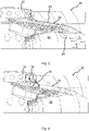
- Figure 5 shows a schematic view of part of an aircraft 20, the view showing a cross section through part of the wing 22, and schematically showing an air duct 24 and air inlet 26 of one embodiment.
- the inlet 26 extends inside the nacelle 28 and is located downstream of the fan (not shown), such that it is positioned within the airflow represented by arrows C.
- Part of the airflow generated by the fan passes into the inlet 26 and flows into and through the duct 24, as represented by arrows D.
- the duct 24 extends through the pylon 29 and then upwards into the leading edge of the wing 22.
- the duct then extends along the leading edge of the wing 22 towards the fuselage of the aircraft 20.
- the pylon 29 is shown partially transparent in the Figure to aid clarity.
- High voltage cables which are not shown in Figure 5 to simplify the diagram run through the duct 24 and then pass into the nacelle 28 to provide power to the electric motor (not shown) housed within. Current passing through the high voltage cables causes them to heat up. The flow of air D through the duct 24 cools the high voltage cables. Heat from the cables is passed to the air in the airflow D, which draws it away from the cables, along the duct, and then out of an air outlet or exhaust vent (not shown) at the end of the duct.
- the fan By having the air inlet 26 located inside the nacelle 28 behind the fan, the fan can be used to generate the airflow D to cool the high voltage cables, both when the aircraft 20 is on the ground and also in flight.
- Figure 6 shows a schematic view of part of another aircraft 30, the view showing a cross section through part of the wing 32, and schematically showing an air duct 34 and air inlet 36 of an alternative embodiment.
- the duct 34 partially extends into the pylon 39, and the inlet 36 is positioned in the leading edge of the pylon 39.
- a cooling airflow E through the duct 34 is generated during flight as the aircraft 30 is moving because the air inlet 36 faces forward in the direction of flight. Ambient air from outside the aircraft therefore enters the air inlet 36 and flows into and through the duct 34, as represented by the arrow E.
- the duct 34 passes through a short section of the pylon 39 and then upwards into the leading edge of the wing 32.
- the duct 34 then extends along the leading edge of the wing 32 towards the fuselage of the aircraft 30.
- the pylon 39 is shown partially transparent in the figure to aid clarity.
- High voltage cables which are not shown in Figure 6 to simplify the diagram run through the duct 34 and then pass into the nacelle 38 to provide power to the electric motor (not shown) housed within. Current passing through the high voltage cables causes them to heat up. The flow of air E through the duct 24 cools the high voltage cables. Heat from the cables is passed to the air in the airflow D, which draws it away from the cables, along the duct, and then out of an air outlet or exhaust vent (not shown) at the end of the duct.
- the air flowing through the duct draws heat away from the high voltage cables to help cool them. This means that the air flowing through the duct will itself warm or heat up. The air can then be exhausted back into the ambient air outside of the aircraft through an exhaust vent or air outlet.
- the warmed air from the duct may be used to warm the cabin air inside the fuselage. This may be done by coupling the airflow from the duct to the cabin air supply in order to help heat the cabin air. This ensures that the heat energy from the high voltage cables is utilised, and not wasted.
- the airflow from the duct that has been heated by the high voltage cables may beneficially be used to heat auxiliary and/or ancillary systems of the aircraft. This also ensures that the heat energy from the high voltage cables is utilised, and not wasted.
- the aircraft may comprise a mixture of propulsion types, with one or more being electric or hybrid propulsion engines, and one or more being more traditional gas turbine jet engines.
- the propulsion engine may alternatively be a different type of electric or hybrid propulsion engine, such as a propeller driven by an electric motor.
Landscapes
- Engineering & Computer Science (AREA)
- Aviation & Aerospace Engineering (AREA)
- Mechanical Engineering (AREA)
- Combustion & Propulsion (AREA)
- Chemical & Material Sciences (AREA)
- General Health & Medical Sciences (AREA)
- Pulmonology (AREA)
- Health & Medical Sciences (AREA)
- General Engineering & Computer Science (AREA)
- Architecture (AREA)
- Civil Engineering (AREA)
- Structural Engineering (AREA)
- Structures Of Non-Positive Displacement Pumps (AREA)
- Wind Motors (AREA)
Abstract
An aircraft (1), comprising: a wing (3) having a leading edge (6); an electric motor (4) mounted on the wing; and an electric power cable (10) in the wing for providing power to the electric motor. Wherein the electric power cable runs through a duct in the wing; the duct (12) comprises an air inlet and an air outlet; and the electric power cable is cooled by air passing through the duct between the air inlet and the air outlet.
Description
- The present invention relates to the cooling of high voltage cables in an aircraft.
- Electric and electric-hybrid propulsion is an important area of development in aircraft and provides many benefits. However, replacing more traditional forms of propulsion, such as gas-turbine jet engines and jet-fuelled turboprop engines, with alternative electric propulsion alternatives gives rise to many challenges and difficulties that must be overcome.
- Electric propulsion, for example a ducted fan driven by an electric motor, requires a high voltage provided from a power supply. Distribution of high voltage power around the aircraft to the electric propulsion system provides a number of challenges in itself. Due to weight and free space constraints, the power supply cables must be of a relatively small diameter. However, having smaller diameter cables in turn creates high temperatures due to the high energy passing through the thinner diameter cables.
- One solution, as described in
US 9,000,295 B1 - Improvements in cable thermal management are therefore required in order that the full benefits of electric and electric-hybrid propulsion in aircraft can be realised.
- A first aspect of the present invention provides an aircraft, comprising: a wing having a leading edge; an electric motor mounted on the wing; and an electric power cable in the wing for providing power to the electric motor. Wherein the electric power cable runs through a duct in the wing; the duct comprises an air inlet and an air outlet; and the electric power cable is cooled by air passing through the duct between the air inlet and the air outlet.
- As a result, the electric power cable is cooled effectively by the air passing through the duct in the wing. The cooling can be carried out passively using external air, and this minimises the need for an additional active cooling system which would increase cost, weight and complexity. The effective cooling can also allow the diameter of the cable to be kept to a minimum, which may help to reduce the size, weight and cost of the power cable.
- The duct may be in the leading edge of the wing. As a result, the duct is positioned close to an ambient air source, and when the aircraft is in flight, there is a significant air pressure differential at the leading edge to encourage ample cooling airflow through the duct.
- The air outlet may be located at an end of the duct near a fuselage of the aircraft. As such, this allows for cooling along substantially the full span of the electrical cable from the electric motor to the fuselage of the aircraft.
- The air outlet may be positioned in a fuselage-to-wing fairing of the aircraft.
- The electric motor may be mounted to the wing by way of a pylon, the pylon comprising a pylon leading edge and the duct may extend at least partially through the pylon. As such, the part of the electric cable that passes through the pylon will also benefit from cooling by the air passing through the duct.
- The electric motor may power a fan, and the air inlet may be provided in the electric motor within an airflow downstream of the fan. As a result, cooling airflow through the duct can be generated by the fan both when the aircraft is in flight as well as on the ground.
- The air inlet may be located in the pylon leading edge. As such, ambient air is forced into the air inlet when the aircraft is in flight.
- The duct may be coupled to the cabin air supply to provide heating for the cabin. This can provide efficient heating of the cabin and reduces waste energy.
- The duct may be coupled to ancillary systems in the aircraft for providing heating to the ancillary systems. This can provide efficient heating of the ancillary systems and reduces waste energy.
- The air outlet may comprise an exhaust vent on the wing at the wing root for exhausting air from the channel. As a result, the cooling air passes through the full length of the duct, and the cable benefits from effective cooling across its full length until it reaches the aircraft fuselage.
- A second aspect of the invention provides a method for cooling an electrical power cable in an aircraft, the aircraft comprising a wing, the method comprising providing the electric power cable through a duct in the wing, the duct comprising an air inlet and an air outlet; and passing cooling air through the duct between the air inlet and the air outlet.
- The electrical power cable may provide power to an electric motor that powers a fan, and the method may further comprise extracting cooling air from an airflow downstream of the fan to pass through the duct.
- The method may further comprise coupling the airflow in the duct to the cabin air supply for use in heating the cabin air.
- The method may further comprise coupling the airflow in the duct to ancillary systems in the aircraft for use in heating the ancillary systems.
- Embodiments of the invention will now be described, by way of example only, with reference to the accompanying drawings, in which:
-
Figure 1 is an above view of an example aircraft according to the invention; -
Figure 2 is a magnified view of part ofFigure 1 ; -
Figure 3 is a perspective view of an example aircraft according to the invention; -
Figure 4 is a magnified view of part ofFigure 3 ; -
Figure 5 is a schematic view through part of an aircraft wing showing a first embodiment of the invention; and -
Figure 6 is a schematic view through part of an aircraft wing showing a second embodiment of the invention. -
Figure 1 shows anaircraft 1 having afuselage 2 andwings 3.Figure 2 shows an enlarged view of part of theaircraft 1 ofFigure 1 , indicated by the dotted circle A.Figure 3 shows a perspective view of theaircraft 1 ofFigure 1 , andFigure 4 shows an enlarged view of part ofFigure 3 , indicated by the dotted oval B. - Attached to the
wings 3 arepropulsion engines 4. Eachpropulsion engine 4 comprises a ducted fan driven by an electric motor housed within anacelle 5. Thewings 3 each have a leadingedge 6 at the front of thewing 3, and thepropulsion engine 4 is attached to thewing 3 by way of apylon 7. - Electric power is provided to drive the electric motors from a power source, which for example may be one or more of a combination of an energy storage solution such as batteries, hydrogen cells, or a hybrid power generating system. The power source in the present example is located in the
fuselage 2 of theaircraft 1. However, alternatively, the power source could be provided in other parts of the aircraft, and may be split into more than one source and distributed across a number of different parts of theaircraft 1. - Electrical power is transferred from the power source to the electric motors in the
propulsion engine 4 by way of high voltage electrical cables. An example of one of the high voltage electrical cables is shown schematically in theFigures 1 to 4 ascable 10. Thecable 10 runs through the inside the leadingedge 6 of thewing 3 through aduct 12. Thecable 10 extends from thefuselage 2 throughduct 12 inside the leadingedge 6 of thewing 3 and then passes through thepylon 7 into thenacelle 5 where it connects with thepropulsion engine 4. Theduct 12 also extends through thepylon 7. - The
duct 12 provides a channel through which air can flow in order to provide cooling to thecable 10. Air enters the duct through an air inlet (not shown), and passes along the length of theduct 12, and finally leaving the duct throughair outlet 14 as shown inFigure 4 . Theair outlet 14 is an exhaust vent provided at the wing root where thewing 3 connects to thefuselage 2. - The air inlet and outlet are positioned such that the pressure difference between them generates sufficient airflow through the duct to cool the high voltage cables. Alternative embodiments may have the air inlet and outlet positioned differently. For example, the outlet may be located above or below the wing, and may be positioned on a fuselage-to-wing fairing of an aircraft.
- This passive air cooling solution provides sufficient cooling to the high voltage cables, but without requiring a complex and expensive active cooling system that may need a heat exchanger, pump and coolant reservoir for example.
-
Figure 5 shows a schematic view of part of anaircraft 20, the view showing a cross section through part of thewing 22, and schematically showing anair duct 24 andair inlet 26 of one embodiment. Theinlet 26 extends inside thenacelle 28 and is located downstream of the fan (not shown), such that it is positioned within the airflow represented by arrows C. Part of the airflow generated by the fan passes into theinlet 26 and flows into and through theduct 24, as represented by arrows D. Theduct 24 extends through thepylon 29 and then upwards into the leading edge of thewing 22. The duct then extends along the leading edge of thewing 22 towards the fuselage of theaircraft 20. - The
pylon 29 is shown partially transparent in the Figure to aid clarity. High voltage cables, which are not shown inFigure 5 to simplify the diagram run through theduct 24 and then pass into thenacelle 28 to provide power to the electric motor (not shown) housed within. Current passing through the high voltage cables causes them to heat up. The flow of air D through theduct 24 cools the high voltage cables. Heat from the cables is passed to the air in the airflow D, which draws it away from the cables, along the duct, and then out of an air outlet or exhaust vent (not shown) at the end of the duct. - By having the
air inlet 26 located inside thenacelle 28 behind the fan, the fan can be used to generate the airflow D to cool the high voltage cables, both when theaircraft 20 is on the ground and also in flight. -
Figure 6 shows a schematic view of part of anotheraircraft 30, the view showing a cross section through part of thewing 32, and schematically showing anair duct 34 andair inlet 36 of an alternative embodiment. In this alternative embodiment, theduct 34 partially extends into thepylon 39, and theinlet 36 is positioned in the leading edge of thepylon 39. A cooling airflow E through theduct 34 is generated during flight as theaircraft 30 is moving because theair inlet 36 faces forward in the direction of flight. Ambient air from outside the aircraft therefore enters theair inlet 36 and flows into and through theduct 34, as represented by the arrow E. Theduct 34 passes through a short section of thepylon 39 and then upwards into the leading edge of thewing 32. As with the previously described embodiment, theduct 34 then extends along the leading edge of thewing 32 towards the fuselage of theaircraft 30. - The
pylon 39 is shown partially transparent in the figure to aid clarity. High voltage cables, which are not shown inFigure 6 to simplify the diagram run through theduct 34 and then pass into thenacelle 38 to provide power to the electric motor (not shown) housed within. Current passing through the high voltage cables causes them to heat up. The flow of air E through theduct 24 cools the high voltage cables. Heat from the cables is passed to the air in the airflow D, which draws it away from the cables, along the duct, and then out of an air outlet or exhaust vent (not shown) at the end of the duct. - In all of these embodiments described, the air flowing through the duct draws heat away from the high voltage cables to help cool them. This means that the air flowing through the duct will itself warm or heat up. The air can then be exhausted back into the ambient air outside of the aircraft through an exhaust vent or air outlet. However, it may be beneficial to utilise the heat generated. For example, the warmed air from the duct may be used to warm the cabin air inside the fuselage. This may be done by coupling the airflow from the duct to the cabin air supply in order to help heat the cabin air. This ensures that the heat energy from the high voltage cables is utilised, and not wasted.
- Alternatively, or additionally, the airflow from the duct that has been heated by the high voltage cables may beneficially be used to heat auxiliary and/or ancillary systems of the aircraft. This also ensures that the heat energy from the high voltage cables is utilised, and not wasted.
- Although the invention has been described above with reference to one or more preferred examples or embodiments, it will be appreciated that various changes or modifications may be made without departing from the scope of the invention as defined in the appended claims.
- For instance, the aircraft may comprise a mixture of propulsion types, with one or more being electric or hybrid propulsion engines, and one or more being more traditional gas turbine jet engines. In addition, although the embodiments described herein have described the propulsion engine as being an electric ducted fan driven by an electric motor, it will be understood that the propulsion engine may alternatively be a different type of electric or hybrid propulsion engine, such as a propeller driven by an electric motor.
- Where the term "or" has been used in the preceding description, this term should be understood to mean "and/or", except where explicitly stated otherwise.
Claims (14)
- An aircraft, comprising:a wing having a leading edge;an electric motor mounted on the wing; andan electric power cable in the wing for providing power to the electric motor; whereinthe electric power cable runs through a duct in the wing;the duct comprises an air inlet and an air outlet; andthe electric power cable is cooled by air passing through the duct between the air inlet and the air outlet.
- An aircraft according to claim 1 wherein the duct is in the leading edge of the wing.
- An aircraft according to any proceeding claim wherein the air outlet is located at an end of the duct near a fuselage of the aircraft.
- An aircraft according to claim 3 wherein the air outlet is positioned in a fuselage-to-wing fairing of the aircraft.
- An aircraft according to any proceeding claim wherein the electric motor is mounted to the wing by way of a pylon, the pylon comprising a pylon leading edge and wherein the duct extends at least partially through the pylon.
- An aircraft according to claim 5 wherein the electric motor powers a fan, and the air inlet is provided in the electric motor within an airflow downstream of the fan.
- An aircraft according to claim 5 wherein the air inlet is located in the pylon leading edge.
- An aircraft according to any proceeding claim wherein the duct is coupled to the cabin air supply to provide heating for the cabin.
- An aircraft according to any proceeding claim wherein the duct is coupled to ancillary systems in the aircraft for providing heating to the ancillary systems.
- An aircraft according to any proceeding claim, wherein the air outlet comprises an exhaust vent on the wing at the wing root for exhausting air from the channel.
- A method for cooling an electrical power cable in an aircraft, the aircraft comprising a wing, the method comprising:providing the electric power cable through a duct in the wing, the duct comprising an air inlet and an air outlet; andpassing cooling air through the duct between the air inlet and the air outlet.
- A method according to claim 11 wherein the electrical power cable provides power to an electric motor that powers a fan, and the method further comprises extracting cooling air from an airflow downstream of the fan to pass through the duct.
- A method according to claim 11 or 12 wherein the method further comprises coupling the airflow in the duct to the cabin air supply for use in heating the cabin air.
- A method according to any one of claims 11 to 13 wherein the method further comprises coupling the airflow in the duct to ancillary systems in the aircraft for use in heating the ancillary systems.
Applications Claiming Priority (1)
| Application Number | Priority Date | Filing Date | Title |
|---|---|---|---|
| GB2016147.7A GB2599726A (en) | 2020-10-12 | 2020-10-12 | Air cooling |
Publications (1)
| Publication Number | Publication Date |
|---|---|
| EP3981688A1 true EP3981688A1 (en) | 2022-04-13 |
Family
ID=73460364
Family Applications (1)
| Application Number | Title | Priority Date | Filing Date |
|---|---|---|---|
| EP21190417.2A Pending EP3981688A1 (en) | 2020-10-12 | 2021-08-09 | Air cooling |
Country Status (4)
| Country | Link |
|---|---|
| US (1) | US11760492B2 (en) |
| EP (1) | EP3981688A1 (en) |
| CN (1) | CN114362067A (en) |
| GB (1) | GB2599726A (en) |
Families Citing this family (2)
| Publication number | Priority date | Publication date | Assignee | Title |
|---|---|---|---|---|
| US20220252008A1 (en) * | 2021-02-08 | 2022-08-11 | General Electric Company | Propulsion system configurations and methods of operation |
| GB2613541A (en) | 2021-11-30 | 2023-06-14 | Airbus Sas | Shielding arrangement for aircraft wiring |
Citations (5)
| Publication number | Priority date | Publication date | Assignee | Title |
|---|---|---|---|---|
| EP1367683A1 (en) * | 2002-05-28 | 2003-12-03 | Airbus Deutschland GmbH | Cable channel |
| EP1921310A1 (en) * | 2006-11-09 | 2008-05-14 | Winwind Oy | Nacelle of a wind power plant |
| US20130214538A1 (en) * | 2012-02-16 | 2013-08-22 | Clipper Windpower, Llc | Air Cooled Power Feeders for Wind Turbine Applications |
| US9000295B1 (en) | 2012-05-10 | 2015-04-07 | The Florida State University Research Foundation, Inc. | Termination for gas cooled cryogenic power cables |
| EP3392149A1 (en) * | 2017-04-21 | 2018-10-24 | General Electric Company | Propulsion system for an aircraft |
Family Cites Families (4)
| Publication number | Priority date | Publication date | Assignee | Title |
|---|---|---|---|---|
| GB473341A (en) * | 1936-04-08 | 1937-10-08 | James Edwin Ellor | Improvements in aircraft |
| US9452841B2 (en) * | 2011-11-29 | 2016-09-27 | Short Brothers Plc | System and method for cooling an aircraft wing |
| EP3931095A4 (en) * | 2019-03-01 | 2022-11-16 | Pratt & Whitney Canada Corp. | AIRCRAFT WITH A HYBRID ELECTRIC PROPULSION SYSTEM WITH IN-WING HOUSED POWER STORAGE |
| GB2587670A (en) * | 2019-10-02 | 2021-04-07 | Advanced Mobility Res And Development Ltd | Systems and methods for aircraft |
-
2020
- 2020-10-12 GB GB2016147.7A patent/GB2599726A/en not_active Withdrawn
-
2021
- 2021-08-09 EP EP21190417.2A patent/EP3981688A1/en active Pending
- 2021-08-27 CN CN202110995448.1A patent/CN114362067A/en active Pending
- 2021-08-31 US US17/463,038 patent/US11760492B2/en active Active
Patent Citations (5)
| Publication number | Priority date | Publication date | Assignee | Title |
|---|---|---|---|---|
| EP1367683A1 (en) * | 2002-05-28 | 2003-12-03 | Airbus Deutschland GmbH | Cable channel |
| EP1921310A1 (en) * | 2006-11-09 | 2008-05-14 | Winwind Oy | Nacelle of a wind power plant |
| US20130214538A1 (en) * | 2012-02-16 | 2013-08-22 | Clipper Windpower, Llc | Air Cooled Power Feeders for Wind Turbine Applications |
| US9000295B1 (en) | 2012-05-10 | 2015-04-07 | The Florida State University Research Foundation, Inc. | Termination for gas cooled cryogenic power cables |
| EP3392149A1 (en) * | 2017-04-21 | 2018-10-24 | General Electric Company | Propulsion system for an aircraft |
Also Published As
| Publication number | Publication date |
|---|---|
| GB2599726A (en) | 2022-04-13 |
| GB202016147D0 (en) | 2020-11-25 |
| CN114362067A (en) | 2022-04-15 |
| US20220111967A1 (en) | 2022-04-14 |
| US11760492B2 (en) | 2023-09-19 |
Similar Documents
| Publication | Publication Date | Title |
|---|---|---|
| EP3473547B1 (en) | Integrated heat management for hybrid propulsion | |
| CN109072710B (en) | Drive system with generator for aircraft | |
| US20260054824A1 (en) | Electric ducted fan propulsor | |
| US10794617B2 (en) | Thermal management system | |
| US8789376B2 (en) | Flade duct turbine cooling and power and thermal management | |
| US20200003115A1 (en) | Turbocharged gas turbine engine with electric power generation for small aircraft electric propulsion | |
| CN103256147A (en) | Thermoelectric generator in turbine engine nozzles | |
| US8714477B2 (en) | Turbomachine support pylon for aircraft | |
| EP4292940A1 (en) | Fuel cell power system for a vehicle | |
| US11760492B2 (en) | Air cooling | |
| EP4509398A1 (en) | Fuel cell aircraft thermal management system | |
| CN103958347A (en) | System and method for cooling an aircraft wing | |
| EP4509409A1 (en) | Nacelle air heat exchanger integration for a hydrogen fueled fuel cell powered aircraft | |
| EP4512721A1 (en) | Liquid hydrogen feed system for fuel cell powered aircraft | |
| US12359587B2 (en) | Gas turbine engine power cable cooling | |
| EP4510250A2 (en) | Low temperature proton exchange membrane charge air heat exchanger | |
| US20250083790A1 (en) | System for the thermal management of an external electric-power-generating nacelle equipping an electrically powered airship, nacelle and airship equipped with said system | |
| US20220307422A1 (en) | Turbine engine system equipped with a fuel deoxygenation system and turboelectric power system | |
| US12523177B1 (en) | Electronic controller cooling for aircraft propulsion system | |
| US20250058889A1 (en) | Configuration for a LH2 Fuel Cell Aircraft with Distributed Systems | |
| US20250058884A1 (en) | Start-Up of High Temperature Proton Exchange Membrane (HTPEM) Fuel Cell Aircraft with Multiple Power Generating Units | |
| US20250060168A1 (en) | Pumped Two-Phase Cooling of Aircraft Electronics | |
| Morioka et al. | A Practical Approach From the MEE Toward Hybrid Propulsion | |
| CN121263360A (en) | Thermal management air duct for an on-board fuel cell system |
Legal Events
| Date | Code | Title | Description |
|---|---|---|---|
| PUAI | Public reference made under article 153(3) epc to a published international application that has entered the european phase |
Free format text: ORIGINAL CODE: 0009012 |
|
| STAA | Information on the status of an ep patent application or granted ep patent |
Free format text: STATUS: THE APPLICATION HAS BEEN PUBLISHED |
|
| AK | Designated contracting states |
Kind code of ref document: A1 Designated state(s): AL AT BE BG CH CY CZ DE DK EE ES FI FR GB GR HR HU IE IS IT LI LT LU LV MC MK MT NL NO PL PT RO RS SE SI SK SM TR |
|
| RBV | Designated contracting states (corrected) |
Designated state(s): AL AT BE BG CH CY CZ DE DK EE ES FI FR GB GR HR HU IE IS IT LI LT LU LV MC MK MT NL NO PL PT RO RS SE SI SK SM TR |