EP3981684A1 - Marine boiler and method of operating a marine boiler - Google Patents
Marine boiler and method of operating a marine boiler Download PDFInfo
- Publication number
- EP3981684A1 EP3981684A1 EP20200428.9A EP20200428A EP3981684A1 EP 3981684 A1 EP3981684 A1 EP 3981684A1 EP 20200428 A EP20200428 A EP 20200428A EP 3981684 A1 EP3981684 A1 EP 3981684A1
- Authority
- EP
- European Patent Office
- Prior art keywords
- exhaust gas
- medium
- marine boiler
- outlet
- boiler
- Prior art date
- Legal status (The legal status is an assumption and is not a legal conclusion. Google has not performed a legal analysis and makes no representation as to the accuracy of the status listed.)
- Withdrawn
Links
- 238000000034 method Methods 0.000 title claims abstract description 18
- 230000005611 electricity Effects 0.000 claims abstract description 16
- 238000007599 discharging Methods 0.000 claims abstract description 6
- 238000010438 heat treatment Methods 0.000 claims abstract description 6
- 238000004891 communication Methods 0.000 claims description 4
- 239000007789 gas Substances 0.000 description 101
- XLYOFNOQVPJJNP-UHFFFAOYSA-N water Substances O XLYOFNOQVPJJNP-UHFFFAOYSA-N 0.000 description 44
- 239000000779 smoke Substances 0.000 description 10
- 229910000975 Carbon steel Inorganic materials 0.000 description 7
- 239000010962 carbon steel Substances 0.000 description 7
- 238000004519 manufacturing process Methods 0.000 description 6
- 239000000463 material Substances 0.000 description 4
- 239000000203 mixture Substances 0.000 description 4
- 239000000567 combustion gas Substances 0.000 description 3
- 238000011084 recovery Methods 0.000 description 3
- 230000004308 accommodation Effects 0.000 description 2
- XAGFODPZIPBFFR-UHFFFAOYSA-N aluminium Chemical compound [Al] XAGFODPZIPBFFR-UHFFFAOYSA-N 0.000 description 2
- 229910052782 aluminium Inorganic materials 0.000 description 2
- 239000012530 fluid Substances 0.000 description 2
- 239000000446 fuel Substances 0.000 description 2
- 239000007792 gaseous phase Substances 0.000 description 2
- 239000007787 solid Substances 0.000 description 2
- 239000010935 stainless steel Substances 0.000 description 2
- 229910001220 stainless steel Inorganic materials 0.000 description 2
- 230000008646 thermal stress Effects 0.000 description 2
- UGFAIRIUMAVXCW-UHFFFAOYSA-N Carbon monoxide Chemical compound [O+]#[C-] UGFAIRIUMAVXCW-UHFFFAOYSA-N 0.000 description 1
- 239000002826 coolant Substances 0.000 description 1
- 238000001816 cooling Methods 0.000 description 1
- 230000009977 dual effect Effects 0.000 description 1
- 239000003546 flue gas Substances 0.000 description 1
- 239000007788 liquid Substances 0.000 description 1
- 239000007791 liquid phase Substances 0.000 description 1
- 239000012071 phase Substances 0.000 description 1
Images




Classifications
-
- B—PERFORMING OPERATIONS; TRANSPORTING
- B63—SHIPS OR OTHER WATERBORNE VESSELS; RELATED EQUIPMENT
- B63J—AUXILIARIES ON VESSELS
- B63J2/00—Arrangements of ventilation, heating, cooling, or air-conditioning
- B63J2/12—Heating; Cooling
-
- F—MECHANICAL ENGINEERING; LIGHTING; HEATING; WEAPONS; BLASTING
- F22—STEAM GENERATION
- F22B—METHODS OF STEAM GENERATION; STEAM BOILERS
- F22B1/00—Methods of steam generation characterised by form of heating method
- F22B1/02—Methods of steam generation characterised by form of heating method by exploitation of the heat content of hot heat carriers
- F22B1/18—Methods of steam generation characterised by form of heating method by exploitation of the heat content of hot heat carriers the heat carrier being a hot gas, e.g. waste gas such as exhaust gas of internal-combustion engines
- F22B1/1807—Methods of steam generation characterised by form of heating method by exploitation of the heat content of hot heat carriers the heat carrier being a hot gas, e.g. waste gas such as exhaust gas of internal-combustion engines using the exhaust gases of combustion engines
-
- F—MECHANICAL ENGINEERING; LIGHTING; HEATING; WEAPONS; BLASTING
- F22—STEAM GENERATION
- F22B—METHODS OF STEAM GENERATION; STEAM BOILERS
- F22B1/00—Methods of steam generation characterised by form of heating method
- F22B1/02—Methods of steam generation characterised by form of heating method by exploitation of the heat content of hot heat carriers
- F22B1/18—Methods of steam generation characterised by form of heating method by exploitation of the heat content of hot heat carriers the heat carrier being a hot gas, e.g. waste gas such as exhaust gas of internal-combustion engines
- F22B1/1861—Waste heat boilers with supplementary firing
-
- F—MECHANICAL ENGINEERING; LIGHTING; HEATING; WEAPONS; BLASTING
- F22—STEAM GENERATION
- F22B—METHODS OF STEAM GENERATION; STEAM BOILERS
- F22B1/00—Methods of steam generation characterised by form of heating method
- F22B1/28—Methods of steam generation characterised by form of heating method in boilers heated electrically
-
- B—PERFORMING OPERATIONS; TRANSPORTING
- B63—SHIPS OR OTHER WATERBORNE VESSELS; RELATED EQUIPMENT
- B63J—AUXILIARIES ON VESSELS
- B63J2/00—Arrangements of ventilation, heating, cooling, or air-conditioning
- B63J2/12—Heating; Cooling
- B63J2002/125—Heating; Cooling making use of waste energy
-
- B—PERFORMING OPERATIONS; TRANSPORTING
- B63—SHIPS OR OTHER WATERBORNE VESSELS; RELATED EQUIPMENT
- B63J—AUXILIARIES ON VESSELS
- B63J3/00—Driving of auxiliaries
- B63J3/04—Driving of auxiliaries from power plant other than propulsion power plant
- B63J2003/043—Driving of auxiliaries from power plant other than propulsion power plant using shore connectors for electric power supply from shore-borne mains, or other electric energy sources external to the vessel, e.g. for docked, or moored vessels
Definitions
- the invention relates to a marine boiler for transferring heat from exhaust gas to a medium onboard a ship, and its design.
- the invention also relates to a method of operating such a marine boiler.
- Boilers are well-known and used in many different heat exchange applications.
- a marine boiler may be arranged on a ship after an exhaust gas source in the form of one or more main engines for propelling the ship, and possibly one or more auxiliary engines, to recover heat from exhaust gas produced by the engines.
- Such a marine boiler is often referred to as a heat recovery marine boiler.
- a medium, typically water, conveyed through the marine boiler is heated by means of heat from the engine exhaust gas conveyed through the marine boiler whereby typically hot water and steam is produced. Hot water and steam leaving the marine boiler is used for different purposes onboard the ship.
- hot water and steam in amounts sufficient to fulfill the needs onboard the ship may be produced by means of the exhaust gas generated by the engines.
- the main engines are typically operated at a relatively low engine load or not at all. Then, insufficient amounts of hot water and steam may be produced by means of the exhaust gas generated by the engines.
- the marine boiler may comprise a burner arranged to be fed with, and burn, oil and/or gas to generate combustion gas for production of hot water and steam.
- a problem is that the exhaust gas from the engines as well as the combustion gas from the burner typically contain pollutions. Pollutions are harmful to the environment and especially undesirable at ports and in sensitive areas.
- An object of the present invention is to provide a marine boiler and a method of operating a marine boiler that at least partly solves the problem above.
- the basic concept of the invention is to provide the marine boiler with external energy for production of hot water and steam.
- the marine boiler and the method for achieving the object above is defined in the appended claims and discussed below.
- a marine boiler according to the invention is arranged for transferring heat from exhaust gas or flue gas or combustion gas to a medium onboard a ship.
- the marine boiler comprises an exhaust gas inlet for receiving exhaust gas from a first exhaust gas source, a first exhaust gas outlet for discharging exhaust gas from said first exhaust gas source, and means for conveying exhaust gas from the first exhaust gas source from said exhaust gas inlet to said first exhaust gas outlet.
- the marine boiler further comprises a medium inlet for receiving the medium, a medium outlet for discharging the medium, and means for conveying the medium from said medium inlet to said medium outlet.
- the marine boiler comprises a circumferential wall inside or within which exhaust gas from the first exhaust gas source and the medium are arranged to be conveyed.
- the marine boiler is characterized in that it further comprises an electric heater for heating said medium by means of electricity supplied from a power source.
- the power source is separate from said first exhaust gas source.
- a certain medium volume is heated by the exhaust gas from the first exhaust gas source or the electric heater or by a combination thereof.
- the medium to be heated can be any suitable medium, for example water.
- the medium may, or may not, change phases, such as go from liquid to gaseous phase, partly or completely, on its way through the marine boiler.
- the medium inlet may be arranged to receive the medium at least partly in liquid phase, e.g. in the form of water, while the medium outlet may be arranged to discharge the medium at least partly in gaseous phase, e.g. in the form of steam.
- the expression “conveying from an inlet to an outlet” and similar means “conveying in a direction from an inlet to an outlet” and not necessarily all the way from the inlet and all the way to the outlet.
- said means for conveying exhaust gas and said means for conveying the medium may, but need not, extend all the way between the respective inlets and outlets.
- the circumferential wall can have any suitable shape, such as the shape of a tube with circular, oval, polygonal, rectangular, etc. , cross-section.
- the circumferential wall may further have any suitable design, such as be solid or hollow, and/or have a uniform or non-uniform thickness.
- the circumferential wall may be a so-called panel wall comprising a number of parallel tubes connected by means of solid wall portions. A cooling medium may be fed through these tubes for cooling exhaust gas conveyed through the marine boiler.
- the components of the marine boiler could be made of any suitable material, for example carbon steel, stainless steel or aluminum.
- the electric heater may have any suitable design.
- the electric heater may be an electrode heater.
- the marine boiler may comprise one or more additional electric heaters for heating said medium, possibly by means of electricity supplied from said power source.
- the power source for supplying electricity to the electric heater may be of any suitable design.
- the power source may be arranged to supply electricity produced from any suitable fuel, solar power, wind power, water power, nuclear power, or any combination thereof.
- the electric heater may be supplied with electricity even when the first exhaust gas source is not operating so as to enable sufficient production of steam and hot water.
- the power source may be a "clean" power source such that operation of the electric heater, which typically takes place when the ship is at a harbor or in a sensitive area, cause release of little or no pollutions.
- the power source may be separate from any exhaust gas source, such as any main or auxiliary engine, onboard the ship. Accordingly, the power source may discharge no exhaust gas.
- the power source for supplying the electric heater with electricity could be arranged onboard the ship. However, according to one embodiment of the invention said power source is separate from the ship, for example onshore. Such an embodiment enables minimizing of any pollutions caused by operation of the electric heater in the immediate vicinity of the ship.
- the first exhaust gas source may be of any suitable type, such as an auxiliary engine, a burner or a turbine.
- the first exhaust gas source comprises an engine, for example a diesel or a dual fuel main engine, for propelling the ship. Such an embodiment may enable automatic generation of steam and hot water when the ship is propelled.
- the marine boiler may be so constructed that said means for conveying exhaust gas from said exhaust gas inlet to said first exhaust gas outlet comprise a first bundle of tubes, and said means for conveying the medium from said medium inlet to said medium outlet comprise said circumferential wall of the marine boiler enclosing said first bundle of tubes.
- the tubes and the circumferential wall could be made of the same material to get essentially the same temperature during operation of the marine boiler, which may enable relatively low thermal stresses in the marine boiler.
- the tubes may have any suitable design, such as be straight, curved or coil- or helix-shaped and have a circular or oval or polygonal cross section, and the tubes may be similar or different from each other.
- the tubes may be provided with surface-enlarging elements, such as spiral fins, plate fins, or fins of any other suitable design.
- the number of tubes may be two or more and they may extend along, and possibly also parallel to, each other.
- a longitudinal center axis of the electric heater may extend parallel or perpendicular to the tubes.
- exhaust gas is fed through the marine boiler in tubes surrounded by the medium to be heated which is enclosed by said circumferential wall of the marine boiler, and heat exchange between exhaust gas and the medium is taking place through walls of the tubes.
- a marine boiler may be referred to as a smoke tube marine boiler.
- the marine boiler may be so constructed that said means for conveying the medium from said medium inlet to said medium outlet comprise one or more tubes. Further, said means for conveying exhaust gas from said exhaust gas inlet to said first exhaust gas outlet may comprise said circumferential wall of the marine boiler enclosing said one or more tubes.
- these one or more tubes may have any suitable design, such as be straight, curved or coil- or helix-shaped and have a circular or oval or polygonal cross section, be similar or different from each other, extend along, and possibly also parallel to each other, and be provided with surface-enlarging elements of any suitable design. Also here, a longitudinal center axis of the electric heater may extend parallel or perpendicular to the tubes.
- the medium to be heated is fed through the marine boiler in tubes surrounded by exhaust gas from the first exhaust gas source, which exhaust gas is enclosed by said circumferential wall of the marine boiler, and heat exchange between exhaust gas and the medium is taking place through walls of the tubes.
- the medium is water
- such a marine boiler may be referred to as a water tube marine boiler.
- the design of the marine boiler may be such that the electric heater is arranged inside, or enclosed by, said circumferential wall. This design may enable a compact and component effective marine boiler.
- the design of the marine boiler may be such that the electric heater is arranged in a container arranged outside said circumferential wall.
- the container may be in communication with said means for conveying the medium from said medium inlet to said medium outlet to enable transfer of said medium between the container and said means for conveying the medium from said medium inlet to said medium outlet.
- the container and said means for conveying the medium from said medium inlet to said medium outlet may communicate by means of one or more pipes extending between the container and said means for conveying the medium from said medium inlet to said medium outlet, for example one pipe for feeding the medium from said means to the container and another pipe for feeding the medium from the container to said means.
- the marine boiler comprises more than one electric heater, they may be arranged in a common container or arranged in one container each. This plurality of containers may be connected in parallel or in series.
- the inventive method of operating a marine boiler to transfer heat from exhaust gas to a medium onboard a ship comprises the step of conveying exhaust gas from a first exhaust gas source from an exhaust gas inlet to a first exhaust gas outlet of the marine boiler.
- the inventive method further comprises conveying the medium from a medium inlet to a medium outlet of the marine boiler.
- the marine boiler comprises a circumferential wall inside which exhaust gas from the first exhaust gas source and the medium are arranged to be conveyed.
- the method is characterized in further comprising the steps of supplying an electric heater with electricity from a power source, which power source is separate from said first exhaust gas source, and heating said medium by means of said electric heater.
- the electric heater may be supplied with electricity when the first exhaust gas source is operating, possibly at only a low load, or only when the first exhaust gas source is idle, i.e. not operating.
- the method may be such that said power source is provided separate from any exhaust gas source onboard the ship.
- the method may be such that said power source is provided separate from the ship, for example onshore.
- the method may be such that an engine for propelling the ship is provided as said first exhaust gas source.
- the electric heater may be provided inside said circumferential wall.
- the electric heater may be provided in a container arranged outside said circumferential wall, and the container may be provided in communication with said means for conveying the medium from said medium inlet to said medium outlet.
- a marine boiler 2 of smoke tube type is illustrated.
- the marine boiler 2 is arranged onboard a ship (not illustrated) and connected to a first exhaust gas source 4 in the form of a diesel engine 4a of the ship by a duct 6, which engine 4a is arranged for propelling the ship.
- Exhaust gas EG1 generated by the diesel engine 4a is fed through the duct 6 to the marine boiler 2 for exhaust gas heat recovery.
- the marine boiler 2 comprises a carbon steel container 8, in turn comprising a lower chamber or header 10, a housing 12 and an upper chamber or header 14 arranged in succession in a vertical, longitudinal direction.
- the lower chamber 10 and the housing 12 both have a circular cylindrical form and are integrally formed so as to have similar cross sections and be concentrically arranged.
- the upper chamber 14 have a partly circular cylindrical form and a smaller cross section than the lower chamber 10 and the housing 12.
- the marine boiler 2 further comprises exhaust gas conveying means 16 in the form of a first bundle of carbon steel tubes 18 extending inside the container 8 between a lower tube plate 22 and an upper tube plate 24 of carbon steel, which plates form lower and upper walls of the housing 12 separating the housing 12 from the lower and upper chambers 10 and 14.
- the essentially similar tubes 18 are straight, have a circular cross section and extend parallel to each other and to a longitudinal center axis c of the housing 12.
- the tubes 18 are arranged to convey exhaust gas EG1 through the container 8, which exhaust gas EG1 is received by the marine boiler 2 through an exhaust gas inlet 26 extending into the lower chamber 10 and discharged by the marine boiler 2 through a first exhaust gas outlet 28 extending out of the upper chamber 14.
- exhaust gas EG1 is fed through the exhaust gas inlet 26, into the lower chamber 10, through the tubes 18, into the upper chamber 14 and through the first exhaust gas outlet 28.
- the marine boiler 2 comprises a furnace 30 arranged inside the container 8 and a second bundle of carbon steel tubes 34 extending inside the housing 12 between the furnace 30 and the upper tube plate 24 of the marine boiler.
- the essentially similar tubes 34 are straight, have a circular cross section and extend parallel to each other and to the longitudinal center axis c of the housing 12.
- the tubes 34 are arranged to convey exhaust gas EG2 from a second exhaust gas source, in the form of an oil-fired burner (not illustrated) arranged inside the furnace 30, through the housing 12 before the exhaust gas EG2 leaves the marine boiler 2 through a second exhaust gas outlet 36 arranged at the upper tube plate 24.
- the housing 12 of the marine boiler 2 is filled with a medium, here water, which is fed into the housing 12 through a medium inlet 38.
- a medium here water
- exhaust gas EG1 is fed through the tubes 18.
- exhaust gas EG2 is fed through the tubes 34.
- the water surrounds and flows around the tubes 18, the tubes 34 and the furnace 30, and since the water is colder than the exhaust gas EG1 and EG2, heat is transferred from the exhaust gas, through walls of the tubes and the furnace, to the water which is heated and leaves the marine boiler 2, in the form of a mixture of water and steam, through a medium outlet 40.
- the housing 12 including a circumferential wall 42 thereof, serves as means 32 for conveying the medium from the medium inlet 38 to the medium outlet 40. Since the housing 12, the tubes 18 and the tubes 34 are made of the same material and all exposed to a common water volume, their temperatures will differ relatively little, which will cause relatively limited thermal stress in the marine boiler.
- the marine boiler 2 further comprises an electric heater 44 in the form of an electrode heater, a cylindrical container 46, an inlet pipe 48 and an outlet pipe 50, which pipes extend between, and fluidly connect, the housing 12 and the container 46.
- the electric heater 44 extends into the cylindrical container 46, a longitudinal center axis of the electric heater 44 extending essentially parallel to the longitudinal center axis c of the housing 12 and a longitudinal center axis of the container 46.
- the electric heater 44 is arranged to be connected to an external power source 52 arranged onshore, for example in a harbor, and supplied with electricity when the ship is not moving and the engine 4a is not operated or operated at low load.
- the cylindrical container 46 is filled with water, which is fed into the container 46 from the housing 12 through the inlet pipe 48.
- heat is transferred from the electrical heater 44 to the water which is heated and fed from the container 46 to the housing 12, in the form of a mixture of water and steam, through the outlet pipe 50.
- the heated water leaves the marine boiler 2 through medium outlet 40.
- the water from the housing 12 is fed through the container 46 by natural circulation.
- the engine 4a When the ship is out at sea, the engine 4a is typically in operation, and steam is generated by means of exhaust gas EG1 from the engine 4a. If not an sufficient amount of steam is generated by means of the exhaust gas EG1 from the engine 4a, the oil-fired burner may also be operated for additional steam generation by means of exhaust gas EG2 from the oil-fired burner.
- the engine 4a when the ship is idle in for example a harbor, the engine 4a may not be operated since no propelling of the ship is to take place. Further, neither the oil-fired burner may be operated so as to minimize the release of harmful pollutions in the harbor. Nevertheless, steam may still be required, and steam production may still be necessary, onboard the ship. Then, the electric heater 44 may be connected to the external power source 52 to produce the required steam, with minimum release of pollutions in the harbor, by means of the electric heater 44.
- hot water and steam can be generated by means of the exhaust gas from the diesel engine, the exhaust gas from the oil-fired burner and the electric heater.
- the electric heater is integrated with the rest of the boiler in such a way as to not require a separate feed water system, steam space, steam pipe or separate safety valves. Since no separate steam space is needed for the electric heater it can be made relatively small with a relatively small foot print. This enables a compact and cost effective marine boiler.
- the marine boiler 54 comprises a plurality, here three, electric heaters 44 arranged in the cylindrical container 46.
- the electric heaters 44 extend into the cylindrical container 46, a respective longitudinal center axis of the electric heaters 44 extending essentially perpendicular to the longitudinal center axis c of the housing 12 and essentially parallel to a longitudinal center axis of the container 46.
- the electric heaters 44 are arranged to be connected to an external power source 52 arranged onshore to be supplied with electricity.
- FIGs. 3a and 3b another marine boiler 56 of smoke tube type is illustrated.
- the marine boiler 56 is very similar to the marine boiler 2 in Figs. 1a and 1b and hereinafter the distinguishing features of the marine boiler 56 will be focused on.
- the marine boiler 56 comprises a plurality, here two, electric heaters 44 but lacks the cylindrical container 46, the inlet pipe 48 and the outlet pipe 50. Instead, the electrical heaters 44 extend into the housing 12 so as to be enclosed by the circumferential wall 42, a longitudinal center axis of the electric heaters 44 extending essentially parallel to the longitudinal center axis c of the housing 12.
- the electric heaters 44 are arranged to be connected to an external power source 52 arranged onshore to be supplied with electricity.
- the electric heaters 44 are surrounded by the same water volume as the tubes 18 and 34 to which water volume heat is transferred during operation of the electric heater 44.
- FIGs. 4a and 4b another marine boiler 58 of smoke tube type is illustrated.
- the marine boiler 58 is very similar to the marine boiler 56 in Figs. 3a and 3b and hereinafter the distinguishing features of the marine boiler 58 will be focused on.
- the electric heaters 44 extend into the housing 12, a respective longitudinal center axis of the electric heaters 44 extending essentially perpendicular to the longitudinal center axis c of the housing 12.
- FIG. 5 another marine boiler 60 of smoke tube type is illustrated.
- the marine boiler 60 is very similar to the marine boiler 54 in Fig. 2 and hereinafter the distinguishing features of the marine boiler 60 will be focused on.
- the marine boiler 60 comprises a plurality, here two, electric heaters 44 arranged in a respective cylindrical container 62 and 64, respectively, which are in fluid serial connection via an intermediate pipe 66.
- An inlet pipe 48 fluidly connects the housing 12 and the container 62 while an outlet pipe 50 fluidly connects the container 64 and the housing 12.
- the electric heaters 44 extend the respective cylindrical containers 62 and 64 with a respective longitudinal center axis of the electric heaters 44 extending essentially perpendicular to the longitudinal center axis c of the housing 12 and essentially parallel to a respective longitudinal center axis of the containers 62 and 64, respectively.
- FIG. 6 another marine boiler 68 of smoke tube type is illustrated.
- the marine boiler 68 is very similar to the marine boiler 60 in Fig. 5 and hereinafter the distinguishing features of the marine boiler 68 will be focused on.
- the marine boiler 68 comprises a plurality, here two, electric heaters 44 arranged in a respective cylindrical container 62 and 64, respectively, which are in fluid parallel connection via an inlet pipe 70 and an outlet pipe 72, which pipes branch so as to connect to both of the cylindrical containers 62 and 64.
- the inlet pipe 70 fluidly connects the housing 12 and the containers 62 and 64 and the outlet pipe 72 fluidly connects the containers 62 and 64 and the housing 12.
- a marine boiler 74 of water tube type is illustrated.
- the marine boiler 74 is arranged onboard a ship (not illustrated) and connected to an first exhaust gas source in the form of a diesel engine 4a of the ship by a duct 76, which engine 4a is arranged for propelling the ship.
- Exhaust gas EG1 generated by the diesel engine 4a is fed through the duct 76 to the marine boiler 74 for exhaust gas heat recovery.
- the marine boiler 74 comprises a carbon steel container 78, in turn comprising a lower chamber or header 80, a housing 82 and an upper chamber or header 84 arranged in succession in a vertical, longitudinal direction.
- the lower chamber 80, the housing 82 and the upper chamber 84 all have a circular cylindrical form and are integrally formed so as to have similar cross sections and be concentrically arranged.
- the marine boiler 74 further comprises a bundle of tubes 86, which extend between a lower tube plate 88 and an upper tube plate 90, which plates form lower and upper walls of the housing 82 separating the housing 82 from the lower and upper chambers 80 and 84.
- the tubes 86 form means 92 for conveying a medium, here water and steam, through the housing 82, water being received by the marine boiler 74 through a medium inlet 94 extending into the lower chamber 80, and steam and hot water being discharged from the marine boiler 74 through a medium outlet 96 extending out of the upper chamber 84.
- the housing 82 is arranged to convey exhaust gas EG1 through the marine boiler 74, which exhaust gas EG1 is received by the marine boiler 74 through an exhaust gas inlet 98 extending into a lower portion of the housing 82 and discharged from the marine boiler 74 through an exhaust gas outlet 100 extending out of an upper portion of the housing 82.
- a circumferential wall 102 of the housing 82 serves as means 104 for conveying the exhaust gas EG1 from the exhaust gas inlet 98 to the exhaust gas outlet 100.
- exhaust gas EG1 is fed through the housing 82. Inside the housing 82 exhaust gas EG1 surrounds and flows around the tubes 86. Further, water is fed from the medium inlet 94 and into the tubes 86, and since the water is colder than the exhaust gas EG1, heat is transferred from the exhaust gas EG1, through walls of the tubes 86, to the water in the tubes 86 which is heated and leaves the marine boiler 74, in the form of steam or a mix of water and steam, through the medium outlet 96.
- the marine boiler 74 further comprises three electric heaters 44 in the form of electrode heaters, a cylindrical container 46, an inlet pipe 106 and an outlet pipe 108, which pipes extend between, and fluidly connect, the housing 82 and the container 46.
- the electric heaters 44 extend into the cylindrical container 46, a respective longitudinal center axis of the electric heaters 44 extending essentially perpendicular to a longitudinal center axis c of the housing 82 and essentially parallel to a longitudinal center axis of the container 46.
- the electric heaters 44 are arranged to be connected to an external power source 52 arranged onshore, for example in a harbor, and supplied with electricity when the ship is not moving and the engine 4a is not operated or operated at low load.
- the cylindrical container 46 is filled with water, which is fed into the container 46 from the housing 82 through the inlet pipe 106.
- heat is transferred from the electrical heaters 44 to the water which is heated and fed from the container 46 to the housing 82, in the form of a mixture of water and steam, through the outlet pipe 108.
- the heated water leaves the marine boiler 74 through medium outlet 96.
- the water from the housing 82 is fed through the container 46 by natural circulation.
- the engine 4a When the ship is out at sea, the engine 4a is typically in operation, and steam is generated by means of exhaust gas EG1 from the engine 4a.
- the engine 4a may not be operated since no propelling of the ship is to take place. Nevertheless, steam may still be required, and steam production may still be necessary, onboard the ship.
- the electric heaters 44 may be connected to the external power source 52 to produce the required steam and hot water, with minimum release of pollutions in the harbor, by means of the electric heaters 44.
- a boiler according to the invention could comprise any number of electric heaters, i.e. one, two, three or more. In the case of more than one electric heater, the electric heaters may be of the same type or different types.
- the electric heater(s) of a boiler could be arranged within the housing or outside the housing of the boiler, i.e. within the external container. In the case of a plurality of electric heaters, a combination is possible, i.e. one or more of them could be arranged within the housing and the rest of them could be arranged outside the housing.
- the electric heater(s) of a boiler could longitudinally extend in any suitable direction, for example parallel or perpendicular to the longitudinal center axis c of the housing of the boiler.
- a combination is possible, i.e. one or more of them could longitudinally extend parallel to the longitudinal center axis c of the housing and the rest of them could longitudinally extend perpendicular to the longitudinal center axis c of the housing.
- these one or more external containers could longitudinally extend in any suitable direction, and the same direction or different directions, such as parallel or perpendicular to the longitudinal center axis c of the housing of the boiler.
- these one or more external containers could have any suitable design, and the same design or different designs.
- the external container(s) need not be circular cylindrical but could have any suitable cross section, such as a polygonal cross section.
- the components of the boiler need not be made of carbon steel but could be made of other materials, such as aluminum or stainless steel.
- the power source for supplying the electric heater(s) with electricity need not be arranged in a harbor but could be arranged somewhere else, on land or not.
- the power source could be a "clean" power source, for example a solar power source, arranged onboard the ship.
- the marine boilers of smoke tube type need not comprise a furnace and tubes extending from the furnace for conveying exhaust gas from a burner arranged inside the furnace. Further, the marine boilers of smoke tube type need not be arranged to receive exhaust gas from an engine. As an example, the marine boiler could be arranged to receive exhaust gas from a first exhaust gas source in the form of a burner, which burner possibly could be arranged inside a furnace, in turn arranged inside a container of the marine boiler. With reference to Fig. 1 , such a marine boiler would lack the exhaust gas inlet 26, the lower chamber 10, the tubes 18, the upper chamber 14 and the exhaust gas outlet 28.
Landscapes
- Engineering & Computer Science (AREA)
- Chemical & Material Sciences (AREA)
- Combustion & Propulsion (AREA)
- Mechanical Engineering (AREA)
- Sustainable Development (AREA)
- Life Sciences & Earth Sciences (AREA)
- Sustainable Energy (AREA)
- Physics & Mathematics (AREA)
- Thermal Sciences (AREA)
- General Engineering & Computer Science (AREA)
- Ocean & Marine Engineering (AREA)
- Exhaust Gas After Treatment (AREA)
- Engine Equipment That Uses Special Cycles (AREA)
Abstract
A marine boiler (2, 54, 56, 58, 60, 68, 74) for transferring heat from exhaust gas (EG1, EG2) to a medium onboard a ship, and a method of operating such a marine boiler, are provided. The marine boiler (2, 54, 56, 58, 60, 68, 74) comprises an exhaust gas inlet (26, 98) for receiving exhaust gas (EG1) from a first exhaust gas source (4), a first exhaust gas outlet (28, 100) for discharging exhaust gas (EG1) from said first exhaust gas source (4), and means (16, 104) for conveying exhaust gas (EG1) from the first exhaust gas source (4) from said exhaust gas inlet (26, 98) to said first exhaust gas outlet (28, 100). The marine boiler (2, 54, 56, 58, 60, 68, 74) further comprises a medium inlet (38, 94) for receiving the medium, a medium outlet (40, 96) for discharging the medium, and means (32, 92) for conveying the medium from said medium inlet (38, 94) to said medium outlet (40, 96). The marine boiler (2, 54, 56, 58, 60, 68, 74) is characterized in further comprising an electric heater (44) for heating said medium by means of electricity supplied from a power source (52), which power source (52) is separate from said first exhaust gas source (4).
Description
- The invention relates to a marine boiler for transferring heat from exhaust gas to a medium onboard a ship, and its design. The invention also relates to a method of operating such a marine boiler.
- Boilers are well-known and used in many different heat exchange applications. For example, a marine boiler may be arranged on a ship after an exhaust gas source in the form of one or more main engines for propelling the ship, and possibly one or more auxiliary engines, to recover heat from exhaust gas produced by the engines. Such a marine boiler is often referred to as a heat recovery marine boiler. In such a marine boiler, a medium, typically water, conveyed through the marine boiler is heated by means of heat from the engine exhaust gas conveyed through the marine boiler whereby typically hot water and steam is produced. Hot water and steam leaving the marine boiler is used for different purposes onboard the ship.
- Out on the open sea where the ship may move at a relatively high speed and the main engines may be operated at a relatively high engine load, hot water and steam in amounts sufficient to fulfill the needs onboard the ship may be produced by means of the exhaust gas generated by the engines. When the ship moves at relatively low speed or does not move at all, which may be the case when the ship is at a port or in a sensitive area, the main engines are typically operated at a relatively low engine load or not at all. Then, insufficient amounts of hot water and steam may be produced by means of the exhaust gas generated by the engines. To secure sufficient production of hot water and steam also when the main engines are operated at low or zero engine load, the marine boiler may comprise a burner arranged to be fed with, and burn, oil and/or gas to generate combustion gas for production of hot water and steam. A problem is that the exhaust gas from the engines as well as the combustion gas from the burner typically contain pollutions. Pollutions are harmful to the environment and especially undesirable at ports and in sensitive areas.
- An object of the present invention is to provide a marine boiler and a method of operating a marine boiler that at least partly solves the problem above. The basic concept of the invention is to provide the marine boiler with external energy for production of hot water and steam. The marine boiler and the method for achieving the object above is defined in the appended claims and discussed below.
- A marine boiler according to the invention is arranged for transferring heat from exhaust gas or flue gas or combustion gas to a medium onboard a ship. The marine boiler comprises an exhaust gas inlet for receiving exhaust gas from a first exhaust gas source, a first exhaust gas outlet for discharging exhaust gas from said first exhaust gas source, and means for conveying exhaust gas from the first exhaust gas source from said exhaust gas inlet to said first exhaust gas outlet. The marine boiler further comprises a medium inlet for receiving the medium, a medium outlet for discharging the medium, and means for conveying the medium from said medium inlet to said medium outlet. Also, the marine boiler comprises a circumferential wall inside or within which exhaust gas from the first exhaust gas source and the medium are arranged to be conveyed. The marine boiler is characterized in that it further comprises an electric heater for heating said medium by means of electricity supplied from a power source. The power source is separate from said first exhaust gas source.
- Thus, according to the present invention, a certain medium volume is heated by the exhaust gas from the first exhaust gas source or the electric heater or by a combination thereof.
- The medium to be heated can be any suitable medium, for example water. The medium may, or may not, change phases, such as go from liquid to gaseous phase, partly or completely, on its way through the marine boiler. For example, the medium inlet may be arranged to receive the medium at least partly in liquid phase, e.g. in the form of water, while the medium outlet may be arranged to discharge the medium at least partly in gaseous phase, e.g. in the form of steam.
- Herein, the expression "conveying from an inlet to an outlet" and similar means "conveying in a direction from an inlet to an outlet" and not necessarily all the way from the inlet and all the way to the outlet. Thus, said means for conveying exhaust gas and said means for conveying the medium may, but need not, extend all the way between the respective inlets and outlets.
- The circumferential wall can have any suitable shape, such as the shape of a tube with circular, oval, polygonal, rectangular, etc. , cross-section. The circumferential wall may further have any suitable design, such as be solid or hollow, and/or have a uniform or non-uniform thickness. As an example, the circumferential wall may be a so-called panel wall comprising a number of parallel tubes connected by means of solid wall portions. A cooling medium may be fed through these tubes for cooling exhaust gas conveyed through the marine boiler.
- The components of the marine boiler could be made of any suitable material, for example carbon steel, stainless steel or aluminum.
- The electric heater may have any suitable design. As an example, the electric heater may be an electrode heater. The marine boiler may comprise one or more additional electric heaters for heating said medium, possibly by means of electricity supplied from said power source.
- The power source for supplying electricity to the electric heater may be of any suitable design. As an example, the power source may be arranged to supply electricity produced from any suitable fuel, solar power, wind power, water power, nuclear power, or any combination thereof.
- In that the power source is separate from the first exhaust gas source, the electric heater may be supplied with electricity even when the first exhaust gas source is not operating so as to enable sufficient production of steam and hot water. The power source may be a "clean" power source such that operation of the electric heater, which typically takes place when the ship is at a harbor or in a sensitive area, cause release of little or no pollutions.
- The power source may be separate from any exhaust gas source, such as any main or auxiliary engine, onboard the ship. Accordingly, the power source may discharge no exhaust gas.
- The power source for supplying the electric heater with electricity could be arranged onboard the ship. However, according to one embodiment of the invention said power source is separate from the ship, for example onshore. Such an embodiment enables minimizing of any pollutions caused by operation of the electric heater in the immediate vicinity of the ship.
- The first exhaust gas source may be of any suitable type, such as an auxiliary engine, a burner or a turbine. However, according to one embodiment, the first exhaust gas source comprises an engine, for example a diesel or a dual fuel main engine, for propelling the ship. Such an embodiment may enable automatic generation of steam and hot water when the ship is propelled.
- The marine boiler may be so constructed that said means for conveying exhaust gas from said exhaust gas inlet to said first exhaust gas outlet comprise a first bundle of tubes, and said means for conveying the medium from said medium inlet to said medium outlet comprise said circumferential wall of the marine boiler enclosing said first bundle of tubes.
- The tubes and the circumferential wall could be made of the same material to get essentially the same temperature during operation of the marine boiler, which may enable relatively low thermal stresses in the marine boiler.
- The tubes may have any suitable design, such as be straight, curved or coil- or helix-shaped and have a circular or oval or polygonal cross section, and the tubes may be similar or different from each other. The tubes may be provided with surface-enlarging elements, such as spiral fins, plate fins, or fins of any other suitable design.
- The number of tubes may be two or more and they may extend along, and possibly also parallel to, each other. A longitudinal center axis of the electric heater may extend parallel or perpendicular to the tubes.
- According to this embodiment, exhaust gas is fed through the marine boiler in tubes surrounded by the medium to be heated which is enclosed by said circumferential wall of the marine boiler, and heat exchange between exhaust gas and the medium is taking place through walls of the tubes. Such a marine boiler may be referred to as a smoke tube marine boiler.
- Instead of being designed as a smoke tube marine boiler, the marine boiler may be so constructed that said means for conveying the medium from said medium inlet to said medium outlet comprise one or more tubes. Further, said means for conveying exhaust gas from said exhaust gas inlet to said first exhaust gas outlet may comprise said circumferential wall of the marine boiler enclosing said one or more tubes.
- Also these one or more tubes may have any suitable design, such as be straight, curved or coil- or helix-shaped and have a circular or oval or polygonal cross section, be similar or different from each other, extend along, and possibly also parallel to each other, and be provided with surface-enlarging elements of any suitable design. Also here, a longitudinal center axis of the electric heater may extend parallel or perpendicular to the tubes.
- According to this embodiment, the medium to be heated is fed through the marine boiler in tubes surrounded by exhaust gas from the first exhaust gas source, which exhaust gas is enclosed by said circumferential wall of the marine boiler, and heat exchange between exhaust gas and the medium is taking place through walls of the tubes. If the medium is water, such a marine boiler may be referred to as a water tube marine boiler.
- The design of the marine boiler may be such that the electric heater is arranged inside, or enclosed by, said circumferential wall. This design may enable a compact and component effective marine boiler.
- Alternatively, the design of the marine boiler may be such that the electric heater is arranged in a container arranged outside said circumferential wall. Further, the container may be in communication with said means for conveying the medium from said medium inlet to said medium outlet to enable transfer of said medium between the container and said means for conveying the medium from said medium inlet to said medium outlet. As an example, the container and said means for conveying the medium from said medium inlet to said medium outlet may communicate by means of one or more pipes extending between the container and said means for conveying the medium from said medium inlet to said medium outlet, for example one pipe for feeding the medium from said means to the container and another pipe for feeding the medium from the container to said means. In case the marine boiler comprises more than one electric heater, they may be arranged in a common container or arranged in one container each. This plurality of containers may be connected in parallel or in series.
- As used herein, "communicating" and similar means "communicating directly or indirectly".
- The inventive method of operating a marine boiler to transfer heat from exhaust gas to a medium onboard a ship, comprises the step of conveying exhaust gas from a first exhaust gas source from an exhaust gas inlet to a first exhaust gas outlet of the marine boiler. The inventive method further comprises conveying the medium from a medium inlet to a medium outlet of the marine boiler. The marine boiler comprises a circumferential wall inside which exhaust gas from the first exhaust gas source and the medium are arranged to be conveyed. The method is characterized in further comprising the steps of supplying an electric heater with electricity from a power source, which power source is separate from said first exhaust gas source, and heating said medium by means of said electric heater.
- The electric heater may be supplied with electricity when the first exhaust gas source is operating, possibly at only a low load, or only when the first exhaust gas source is idle, i.e. not operating.
- The method may be such that said power source is provided separate from any exhaust gas source onboard the ship.
- The method may be such that said power source is provided separate from the ship, for example onshore.
- The method may be such that an engine for propelling the ship is provided as said first exhaust gas source.
- The electric heater may be provided inside said circumferential wall.
- Alternatively, the electric heater may be provided in a container arranged outside said circumferential wall, and the container may be provided in communication with said means for conveying the medium from said medium inlet to said medium outlet.
- The above discussed advantages of the different embodiments of the marine boiler according to the invention are naturally transferable to the different embodiments of the method according to the invention.
- Still other objectives, features, aspects and advantages of the invention will appear from the following detailed description as well as from the drawings.
- The invention will now be described in more detail with reference to the appended schematic drawings, in which
-
Fig. 1a schematically illustrates an engine, a marine boiler and an external power source, partly in longitudinal cross section, according to a first embodiment, -
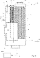
Fig. 1b illustrates a schematic top view of the marine boiler according to the first embodiment, -
Fig. 2 schematically illustrates an engine, a marine boiler and an external power source, partly in longitudinal cross section, according to a second embodiment, -
Fig. 3a schematically illustrates an engine, a marine boiler and an external power source, partly in longitudinal cross section, according to a third embodiment, -
Fig. 3b illustrates a schematic transverse cross section, along line A-A inFig. 3a , of the marine boiler according to the third embodiment, -
Fig. 4a schematically illustrates an engine, a marine boiler and an external power source, partly in longitudinal cross section, according to a fourth embodiment, -
Fig. 4b illustrates a schematic transverse cross section, along line B-B inFig. 4a , of the marine boiler according to the fourth embodiment, -
Fig. 5 schematically illustrates an engine, a marine boiler and an external power source, partly in longitudinal cross section, according to a fifth embodiment, -
Fig. 6 schematically illustrates an engine, a marine boiler and an external power source, partly in longitudinal cross section, according to a sixth embodiment, and -
Fig. 7 schematically illustrates an engine, a marine boiler and an external power source, partly in longitudinal cross section, according to a seventh embodiment. - In
Figs. 1a and1b amarine boiler 2 of smoke tube type is illustrated. Themarine boiler 2 is arranged onboard a ship (not illustrated) and connected to a first exhaust gas source 4 in the form of a diesel engine 4a of the ship by aduct 6, which engine 4a is arranged for propelling the ship. Exhaust gas EG1 generated by the diesel engine 4a is fed through theduct 6 to themarine boiler 2 for exhaust gas heat recovery. Themarine boiler 2 comprises acarbon steel container 8, in turn comprising a lower chamber orheader 10, ahousing 12 and an upper chamber orheader 14 arranged in succession in a vertical, longitudinal direction. Thelower chamber 10 and thehousing 12 both have a circular cylindrical form and are integrally formed so as to have similar cross sections and be concentrically arranged. Theupper chamber 14 have a partly circular cylindrical form and a smaller cross section than thelower chamber 10 and thehousing 12. - The
marine boiler 2 further comprises exhaust gas conveying means 16 in the form of a first bundle ofcarbon steel tubes 18 extending inside thecontainer 8 between alower tube plate 22 and anupper tube plate 24 of carbon steel, which plates form lower and upper walls of thehousing 12 separating thehousing 12 from the lower andupper chambers similar tubes 18 are straight, have a circular cross section and extend parallel to each other and to a longitudinal center axis c of thehousing 12. Thetubes 18 are arranged to convey exhaust gas EG1 through thecontainer 8, which exhaust gas EG1 is received by themarine boiler 2 through anexhaust gas inlet 26 extending into thelower chamber 10 and discharged by themarine boiler 2 through a firstexhaust gas outlet 28 extending out of theupper chamber 14. When the diesel engine 4a is running, exhaust gas EG1 is fed through theexhaust gas inlet 26, into thelower chamber 10, through thetubes 18, into theupper chamber 14 and through the firstexhaust gas outlet 28. - Further, the
marine boiler 2 comprises afurnace 30 arranged inside thecontainer 8 and a second bundle ofcarbon steel tubes 34 extending inside thehousing 12 between thefurnace 30 and theupper tube plate 24 of the marine boiler. The essentiallysimilar tubes 34 are straight, have a circular cross section and extend parallel to each other and to the longitudinal center axis c of thehousing 12. Thetubes 34 are arranged to convey exhaust gas EG2 from a second exhaust gas source, in the form of an oil-fired burner (not illustrated) arranged inside thefurnace 30, through thehousing 12 before the exhaust gas EG2 leaves themarine boiler 2 through a secondexhaust gas outlet 36 arranged at theupper tube plate 24. - The
housing 12 of themarine boiler 2 is filled with a medium, here water, which is fed into thehousing 12 through amedium inlet 38. During operation of the engine 4, exhaust gas EG1 is fed through thetubes 18. Further, if the oil-fired burner is running, exhaust gas EG2 is fed through thetubes 34. The water surrounds and flows around thetubes 18, thetubes 34 and thefurnace 30, and since the water is colder than the exhaust gas EG1 and EG2, heat is transferred from the exhaust gas, through walls of the tubes and the furnace, to the water which is heated and leaves themarine boiler 2, in the form of a mixture of water and steam, through amedium outlet 40. Thus, thehousing 12, including acircumferential wall 42 thereof, serves as means 32 for conveying the medium from themedium inlet 38 to themedium outlet 40. Since thehousing 12, thetubes 18 and thetubes 34 are made of the same material and all exposed to a common water volume, their temperatures will differ relatively little, which will cause relatively limited thermal stress in the marine boiler. - The
marine boiler 2 further comprises anelectric heater 44 in the form of an electrode heater, acylindrical container 46, aninlet pipe 48 and anoutlet pipe 50, which pipes extend between, and fluidly connect, thehousing 12 and thecontainer 46. Theelectric heater 44 extends into thecylindrical container 46, a longitudinal center axis of theelectric heater 44 extending essentially parallel to the longitudinal center axis c of thehousing 12 and a longitudinal center axis of thecontainer 46. Theelectric heater 44 is arranged to be connected to anexternal power source 52 arranged onshore, for example in a harbor, and supplied with electricity when the ship is not moving and the engine 4a is not operated or operated at low load. - The
cylindrical container 46 is filled with water, which is fed into thecontainer 46 from thehousing 12 through theinlet pipe 48. During operation of theelectric heater 44 heat is transferred from theelectrical heater 44 to the water which is heated and fed from thecontainer 46 to thehousing 12, in the form of a mixture of water and steam, through theoutlet pipe 50. The heated water leaves themarine boiler 2 throughmedium outlet 40. The water from thehousing 12 is fed through thecontainer 46 by natural circulation. - When the ship is out at sea, the engine 4a is typically in operation, and steam is generated by means of exhaust gas EG1 from the engine 4a. If not an sufficient amount of steam is generated by means of the exhaust gas EG1 from the engine 4a, the oil-fired burner may also be operated for additional steam generation by means of exhaust gas EG2 from the oil-fired burner. However, when the ship is idle in for example a harbor, the engine 4a may not be operated since no propelling of the ship is to take place. Further, neither the oil-fired burner may be operated so as to minimize the release of harmful pollutions in the harbor. Nevertheless, steam may still be required, and steam production may still be necessary, onboard the ship. Then, the
electric heater 44 may be connected to theexternal power source 52 to produce the required steam, with minimum release of pollutions in the harbor, by means of theelectric heater 44. - Thus, in the
marine boiler 2 hot water and steam can be generated by means of the exhaust gas from the diesel engine, the exhaust gas from the oil-fired burner and the electric heater. The electric heater is integrated with the rest of the boiler in such a way as to not require a separate feed water system, steam space, steam pipe or separate safety valves. Since no separate steam space is needed for the electric heater it can be made relatively small with a relatively small foot print. This enables a compact and cost effective marine boiler. - In
Fig. 2 anothermarine boiler 54 of smoke tube type is illustrated. Themarine boiler 54 is very similar to themarine boiler 2 inFigs. 1a and1b and hereinafter the distinguishing features of themarine boiler 54 will be focused on. Themarine boiler 54 comprises a plurality, here three,electric heaters 44 arranged in thecylindrical container 46. Theelectric heaters 44 extend into thecylindrical container 46, a respective longitudinal center axis of theelectric heaters 44 extending essentially perpendicular to the longitudinal center axis c of thehousing 12 and essentially parallel to a longitudinal center axis of thecontainer 46. Theelectric heaters 44 are arranged to be connected to anexternal power source 52 arranged onshore to be supplied with electricity. - In
Figs. 3a and3b anothermarine boiler 56 of smoke tube type is illustrated. Themarine boiler 56 is very similar to themarine boiler 2 inFigs. 1a and1b and hereinafter the distinguishing features of themarine boiler 56 will be focused on. Themarine boiler 56 comprises a plurality, here two,electric heaters 44 but lacks thecylindrical container 46, theinlet pipe 48 and theoutlet pipe 50. Instead, theelectrical heaters 44 extend into thehousing 12 so as to be enclosed by thecircumferential wall 42, a longitudinal center axis of theelectric heaters 44 extending essentially parallel to the longitudinal center axis c of thehousing 12. Theelectric heaters 44 are arranged to be connected to anexternal power source 52 arranged onshore to be supplied with electricity. Thus, theelectric heaters 44 are surrounded by the same water volume as thetubes electric heater 44. - In
Figs. 4a and4b anothermarine boiler 58 of smoke tube type is illustrated. Themarine boiler 58 is very similar to themarine boiler 56 inFigs. 3a and3b and hereinafter the distinguishing features of themarine boiler 58 will be focused on. Theelectric heaters 44 extend into thehousing 12, a respective longitudinal center axis of theelectric heaters 44 extending essentially perpendicular to the longitudinal center axis c of thehousing 12. - In
Fig. 5 anothermarine boiler 60 of smoke tube type is illustrated. Themarine boiler 60 is very similar to themarine boiler 54 inFig. 2 and hereinafter the distinguishing features of themarine boiler 60 will be focused on. Themarine boiler 60 comprises a plurality, here two,electric heaters 44 arranged in a respectivecylindrical container intermediate pipe 66. Aninlet pipe 48 fluidly connects thehousing 12 and thecontainer 62 while anoutlet pipe 50 fluidly connects thecontainer 64 and the housing 12.Theelectric heaters 44 extend the respectivecylindrical containers electric heaters 44 extending essentially perpendicular to the longitudinal center axis c of thehousing 12 and essentially parallel to a respective longitudinal center axis of thecontainers - In
Fig. 6 anothermarine boiler 68 of smoke tube type is illustrated. Themarine boiler 68 is very similar to themarine boiler 60 inFig. 5 and hereinafter the distinguishing features of themarine boiler 68 will be focused on. Themarine boiler 68 comprises a plurality, here two,electric heaters 44 arranged in a respectivecylindrical container inlet pipe 70 and anoutlet pipe 72, which pipes branch so as to connect to both of thecylindrical containers inlet pipe 70 fluidly connects thehousing 12 and thecontainers outlet pipe 72 fluidly connects thecontainers housing 12. - In
Fig. 7 amarine boiler 74 of water tube type is illustrated. Themarine boiler 74 is arranged onboard a ship (not illustrated) and connected to an first exhaust gas source in the form of a diesel engine 4a of the ship by aduct 76, which engine 4a is arranged for propelling the ship. Exhaust gas EG1 generated by the diesel engine 4a is fed through theduct 76 to themarine boiler 74 for exhaust gas heat recovery. Themarine boiler 74 comprises acarbon steel container 78, in turn comprising a lower chamber orheader 80, ahousing 82 and an upper chamber orheader 84 arranged in succession in a vertical, longitudinal direction. Thelower chamber 80, thehousing 82 and theupper chamber 84 all have a circular cylindrical form and are integrally formed so as to have similar cross sections and be concentrically arranged. - The
marine boiler 74 further comprises a bundle oftubes 86, which extend between alower tube plate 88 and anupper tube plate 90, which plates form lower and upper walls of thehousing 82 separating thehousing 82 from the lower andupper chambers tubes 86 form means 92 for conveying a medium, here water and steam, through thehousing 82, water being received by themarine boiler 74 through amedium inlet 94 extending into thelower chamber 80, and steam and hot water being discharged from themarine boiler 74 through amedium outlet 96 extending out of theupper chamber 84. - The
housing 82 is arranged to convey exhaust gas EG1 through themarine boiler 74, which exhaust gas EG1 is received by themarine boiler 74 through anexhaust gas inlet 98 extending into a lower portion of thehousing 82 and discharged from themarine boiler 74 through anexhaust gas outlet 100 extending out of an upper portion of thehousing 82. Acircumferential wall 102 of thehousing 82 serves as means 104 for conveying the exhaust gas EG1 from theexhaust gas inlet 98 to theexhaust gas outlet 100. - During operation of the diesel engine 4a and the
marine boiler 74, exhaust gas EG1 is fed through thehousing 82. Inside thehousing 82 exhaust gas EG1 surrounds and flows around thetubes 86. Further, water is fed from themedium inlet 94 and into thetubes 86, and since the water is colder than the exhaust gas EG1, heat is transferred from the exhaust gas EG1, through walls of thetubes 86, to the water in thetubes 86 which is heated and leaves themarine boiler 74, in the form of steam or a mix of water and steam, through themedium outlet 96. - The
marine boiler 74 further comprises threeelectric heaters 44 in the form of electrode heaters, acylindrical container 46, aninlet pipe 106 and anoutlet pipe 108, which pipes extend between, and fluidly connect, thehousing 82 and thecontainer 46. Theelectric heaters 44 extend into thecylindrical container 46, a respective longitudinal center axis of theelectric heaters 44 extending essentially perpendicular to a longitudinal center axis c of thehousing 82 and essentially parallel to a longitudinal center axis of thecontainer 46. Theelectric heaters 44 are arranged to be connected to anexternal power source 52 arranged onshore, for example in a harbor, and supplied with electricity when the ship is not moving and the engine 4a is not operated or operated at low load. - The
cylindrical container 46 is filled with water, which is fed into thecontainer 46 from thehousing 82 through theinlet pipe 106. During operation of theelectric heaters 44 heat is transferred from theelectrical heaters 44 to the water which is heated and fed from thecontainer 46 to thehousing 82, in the form of a mixture of water and steam, through theoutlet pipe 108. The heated water leaves themarine boiler 74 throughmedium outlet 96. The water from thehousing 82 is fed through thecontainer 46 by natural circulation. - When the ship is out at sea, the engine 4a is typically in operation, and steam is generated by means of exhaust gas EG1 from the engine 4a. However, when the ship is idle in for example a harbor, the engine 4a may not be operated since no propelling of the ship is to take place. Nevertheless, steam may still be required, and steam production may still be necessary, onboard the ship. Then, the
electric heaters 44 may be connected to theexternal power source 52 to produce the required steam and hot water, with minimum release of pollutions in the harbor, by means of theelectric heaters 44. - The above described embodiments of the present invention should only be seen as examples. A person skilled in the art realizes that the embodiments discussed can be varied and combined in a number of ways without deviating from the inventive conception.
- For example, a boiler according to the invention could comprise any number of electric heaters, i.e. one, two, three or more. In the case of more than one electric heater, the electric heaters may be of the same type or different types.
- The electric heater(s) of a boiler could be arranged within the housing or outside the housing of the boiler, i.e. within the external container. In the case of a plurality of electric heaters, a combination is possible, i.e. one or more of them could be arranged within the housing and the rest of them could be arranged outside the housing.
- Further, in the case of a plurality of electric heaters, all or some of them could be arranged in a common external container or in a respective external container.
- In the case of a plurality of external containers, these could be fluidly connected in parallel, in series, or separately to the housing of the boiler. Any combination thereof is also possible.
- The electric heater(s) of a boiler could longitudinally extend in any suitable direction, for example parallel or perpendicular to the longitudinal center axis c of the housing of the boiler. In the case of a plurality of electric heaters, a combination is possible, i.e. one or more of them could longitudinally extend parallel to the longitudinal center axis c of the housing and the rest of them could longitudinally extend perpendicular to the longitudinal center axis c of the housing.
- In the case of a boiler comprising one or more external containers for accommodation of one or more electric heaters, these one or more external containers could longitudinally extend in any suitable direction, and the same direction or different directions, such as parallel or perpendicular to the longitudinal center axis c of the housing of the boiler.
- Further, in the case of a boiler comprising one or more external containers for accommodation of one or more electric heaters, these one or more external containers could have any suitable design, and the same design or different designs. Thus, the external container(s) need not be circular cylindrical but could have any suitable cross section, such as a polygonal cross section.
- Naturally, also other components of the boiler could have alternative designs than illustrated in the drawings.
- The components of the boiler need not be made of carbon steel but could be made of other materials, such as aluminum or stainless steel.
- Combinations of the above design alternatives are possible.
- The power source for supplying the electric heater(s) with electricity need not be arranged in a harbor but could be arranged somewhere else, on land or not. As an example, the power source could be a "clean" power source, for example a solar power source, arranged onboard the ship.
- The marine boilers of smoke tube type need not comprise a furnace and tubes extending from the furnace for conveying exhaust gas from a burner arranged inside the furnace. Further, the marine boilers of smoke tube type need not be arranged to receive exhaust gas from an engine. As an example, the marine boiler could be arranged to receive exhaust gas from a first exhaust gas source in the form of a burner, which burner possibly could be arranged inside a furnace, in turn arranged inside a container of the marine boiler. With reference to
Fig. 1 , such a marine boiler would lack theexhaust gas inlet 26, thelower chamber 10, thetubes 18, theupper chamber 14 and theexhaust gas outlet 28. - It should be stressed that a description of details not relevant to the present invention has been omitted and that the figures are just schematic and not drawn according to scale. It should also be said that some of the figures have been more simplified than others. Therefore, some components may be illustrated in one figure but left out in another figure. Finally, as used herein, the prefixes "first", "second", "top", "bottom", "upper", "lower", "horizontal", "vertical" etc. are used only to distinguish between different components and pose no requirements as regards relative positioning or orientation.
Claims (15)
- A marine boiler (2, 54, 56, 58, 60, 68, 74) for transferring heat from exhaust gas (EG1, EG2) to a medium onboard a ship, the marine boiler (2, 54, 56, 58, 60, 68, 74) comprising an exhaust gas inlet (26, 98) for receiving exhaust gas (EG1) from a first exhaust gas source (4), a first exhaust gas outlet (28, 100) for discharging exhaust gas (EG1) from said first exhaust gas source (4), means (16, 104) for conveying exhaust gas (EG1) from the first exhaust gas source (4) from said exhaust gas inlet (26, 98) to said first exhaust gas outlet (28, 100), a medium inlet (38, 94) for receiving the medium, a medium outlet (40, 96) for discharging the medium, means (32, 92) for conveying the medium from said medium inlet (38, 94) to said medium outlet (40, 96), and a circumferential wall (42, 102) inside which exhaust gas (EG1) from the first exhaust gas source (4) and the medium are arranged to be conveyed, characterized in further comprising an electric heater (44) for heating said medium by means of electricity supplied from a power source (52), which power source (52) is separate from said first exhaust gas source (4).
- A marine boiler (2, 54, 56, 58, 60, 68, 74) according to claim 1, wherein said power source (52) is separate from any exhaust gas source onboard the ship.
- A marine boiler (2, 54, 56, 58, 60, 68, 74) according to any of the preceding claims, wherein said power source (52) is separate from the ship.
- A marine boiler (2, 54, 56, 58, 60, 68, 74) according to any of the preceding claims, wherein said power source (52) is arranged onshore.
- A marine boiler (2, 54, 56, 58, 60, 68, 74) according to any of the preceding claims, wherein said first exhaust gas source (4) comprises an engine (4a) for propelling the ship.
- A marine boiler (2, 54, 56, 58, 60, 68) according to any of the preceding claims, wherein said means (16) for conveying exhaust gas (EG1) from said exhaust gas inlet (26) to said first exhaust gas outlet (28) comprise a first bundle of tubes (18), and said means (32) for conveying the medium from said medium inlet (38) to said medium outlet (40) comprise said circumferential wall (42) of the marine boiler (2, 54, 56, 58, 60, 68) enclosing said first bundle of tubes (18).
- A marine boiler (74) according to any of claims 1-5, wherein said means (92) for conveying the medium from said medium inlet (94) to said medium outlet (96) comprise one or more tubes (86), and said means (104) for conveying exhaust gas (EG1) from said exhaust gas inlet (98) to said first exhaust gas outlet (100) comprise said circumferential wall (102) of the marine boiler (74) enclosing said one or more tubes (86).
- A marine boiler (56, 58) according to any of the preceding claims, wherein the electric heater (44) is arranged inside said circumferential wall (42).
- A marine boiler (2, 54, 60, 68, 74) according to any of claims 1-7, wherein the electric heater (44) is arranged in a container (46, 62, 64) arranged outside said circumferential wall (42, 102), which container (46, 62, 64) is in communication with said means (16,104) for conveying the medium from said medium inlet (38, 94) to said medium outlet (40, 96).
- A method of operating a marine boiler (2, 54, 56, 58, 60, 68, 74) to transfer heat from exhaust gas (EG1, EG2) to a medium onboard a ship, comprising,
conveying exhaust gas (EG1) from a first exhaust gas source (4) from an exhaust gas inlet (26, 98) to a first exhaust gas outlet (28, 100) of the marine boiler (2, 54, 56, 58, 60, 68, 74), and
conveying the medium from a medium inlet (38, 94) to a medium outlet (40, 96) of the marine boiler (2, 54, 56, 58, 60, 68, 74), the marine boiler (2, 54, 56, 58, 60, 68, 74) comprising a circumferential wall (42, 102) inside which exhaust gas (EG1) from the first exhaust gas source (4) and the medium are arranged to be conveyed,
characterized in further comprising,
supplying an electric heater (44) with electricity from a power source (52), which power source (52) is separate from said first exhaust gas source (4), and heating said medium by means of said electric heater (44). - A method according to claim 10, comprising providing said power source (52) separate from any exhaust gas source onboard the ship.
- A method according to any of claims 10-11, comprising providing said power source (52) onshore.
- A method according to any of claims 10-12, comprising providing an engine (4a) for propelling the ship as said first exhaust gas source (4).
- A method according to any of the claims 10-13, comprising providing the electric heater (44) inside said circumferential wall (42, 102).
- A method according to any of claims 10-13, comprising providing the electric heater (44) in a container (46, 62, 64) arranged outside said circumferential wall (42, 102), and providing the container (46, 62, 64) in communication with said means (16, 104) for conveying the medium from said medium inlet (38, 94) to said medium outlet (40, 96).
Priority Applications (6)
| Application Number | Priority Date | Filing Date | Title |
|---|---|---|---|
| EP20200428.9A EP3981684A1 (en) | 2020-10-07 | 2020-10-07 | Marine boiler and method of operating a marine boiler |
| PCT/EP2021/075921 WO2022073756A1 (en) | 2020-10-07 | 2021-09-21 | Marine boiler and method of operating a marine boiler |
| JP2023521637A JP7700223B2 (en) | 2020-10-07 | 2021-09-21 | Marine boiler and method for operating a marine boiler |
| EP21782503.3A EP4225637A1 (en) | 2020-10-07 | 2021-09-21 | Marine boiler and method of operating a marine boiler |
| KR1020237014970A KR102884903B1 (en) | 2020-10-07 | 2021-09-21 | Marine boilers and methods of operating marine boilers |
| CN202180068471.4A CN116323389A (en) | 2020-10-07 | 2021-09-21 | Marine boiler and method of operating a marine boiler |
Applications Claiming Priority (1)
| Application Number | Priority Date | Filing Date | Title |
|---|---|---|---|
| EP20200428.9A EP3981684A1 (en) | 2020-10-07 | 2020-10-07 | Marine boiler and method of operating a marine boiler |
Publications (1)
| Publication Number | Publication Date |
|---|---|
| EP3981684A1 true EP3981684A1 (en) | 2022-04-13 |
Family
ID=72801305
Family Applications (2)
| Application Number | Title | Priority Date | Filing Date |
|---|---|---|---|
| EP20200428.9A Withdrawn EP3981684A1 (en) | 2020-10-07 | 2020-10-07 | Marine boiler and method of operating a marine boiler |
| EP21782503.3A Pending EP4225637A1 (en) | 2020-10-07 | 2021-09-21 | Marine boiler and method of operating a marine boiler |
Family Applications After (1)
| Application Number | Title | Priority Date | Filing Date |
|---|---|---|---|
| EP21782503.3A Pending EP4225637A1 (en) | 2020-10-07 | 2021-09-21 | Marine boiler and method of operating a marine boiler |
Country Status (5)
| Country | Link |
|---|---|
| EP (2) | EP3981684A1 (en) |
| JP (1) | JP7700223B2 (en) |
| KR (1) | KR102884903B1 (en) |
| CN (1) | CN116323389A (en) |
| WO (1) | WO2022073756A1 (en) |
Citations (4)
| Publication number | Priority date | Publication date | Assignee | Title |
|---|---|---|---|---|
| WO2012118382A1 (en) * | 2011-03-03 | 2012-09-07 | Ulmatec Pyro As | Method and system for optimal use of heat energy produced in a thermal system onboard a marine unit |
| KR20160072452A (en) * | 2014-12-15 | 2016-06-23 | 재단법인 중소조선연구원 | anti-icing system for recycling exhausting gas heat of ship sailing frozen sea |
| CN111547219A (en) * | 2020-05-20 | 2020-08-18 | 江南造船(集团)有限责任公司 | Recycling device for condensed water and waste heat of ship and using method thereof |
| CN111605667A (en) * | 2020-06-01 | 2020-09-01 | 江苏科技大学 | A multi-energy complementary ship cold and hot water system |
Family Cites Families (6)
| Publication number | Priority date | Publication date | Assignee | Title |
|---|---|---|---|---|
| JPH0352240Y2 (en) * | 1986-12-25 | 1991-11-12 | ||
| US7219502B2 (en) | 2003-08-12 | 2007-05-22 | Excelerate Energy Limited Partnership | Shipboard regasification for LNG carriers with alternate propulsion plants |
| JP2008178228A (en) * | 2007-01-19 | 2008-07-31 | Terasaki Electric Co Ltd | Method and system for supplying power from land to ship |
| JP5381084B2 (en) | 2008-12-24 | 2014-01-08 | アイシン精機株式会社 | Cogeneration system and hot water storage system |
| JP5611278B2 (en) | 2012-06-21 | 2014-10-22 | 三浦工業株式会社 | Ship boiler |
| JP5611281B2 (en) * | 2012-07-11 | 2014-10-22 | 三浦工業株式会社 | Ship boiler |
-
2020
- 2020-10-07 EP EP20200428.9A patent/EP3981684A1/en not_active Withdrawn
-
2021
- 2021-09-21 JP JP2023521637A patent/JP7700223B2/en active Active
- 2021-09-21 WO PCT/EP2021/075921 patent/WO2022073756A1/en not_active Ceased
- 2021-09-21 EP EP21782503.3A patent/EP4225637A1/en active Pending
- 2021-09-21 CN CN202180068471.4A patent/CN116323389A/en active Pending
- 2021-09-21 KR KR1020237014970A patent/KR102884903B1/en active Active
Patent Citations (4)
| Publication number | Priority date | Publication date | Assignee | Title |
|---|---|---|---|---|
| WO2012118382A1 (en) * | 2011-03-03 | 2012-09-07 | Ulmatec Pyro As | Method and system for optimal use of heat energy produced in a thermal system onboard a marine unit |
| KR20160072452A (en) * | 2014-12-15 | 2016-06-23 | 재단법인 중소조선연구원 | anti-icing system for recycling exhausting gas heat of ship sailing frozen sea |
| CN111547219A (en) * | 2020-05-20 | 2020-08-18 | 江南造船(集团)有限责任公司 | Recycling device for condensed water and waste heat of ship and using method thereof |
| CN111605667A (en) * | 2020-06-01 | 2020-09-01 | 江苏科技大学 | A multi-energy complementary ship cold and hot water system |
Also Published As
| Publication number | Publication date |
|---|---|
| WO2022073756A1 (en) | 2022-04-14 |
| JP7700223B2 (en) | 2025-06-30 |
| EP4225637A1 (en) | 2023-08-16 |
| KR102884903B1 (en) | 2025-11-12 |
| CN116323389A (en) | 2023-06-23 |
| KR20230078800A (en) | 2023-06-02 |
| JP2023544865A (en) | 2023-10-25 |
Similar Documents
| Publication | Publication Date | Title |
|---|---|---|
| US7614366B2 (en) | High efficiency water heater | |
| EP3781864B1 (en) | Vaporization apparatus | |
| CA2287177A1 (en) | Once-through steam generator and method for starting up a once-through steam generator | |
| US9945554B2 (en) | Method of steam generation by spraying water onto a duct within a chamber having divider walls | |
| US20130269344A1 (en) | Indirectly heated gas turbine system | |
| US4998508A (en) | Condensing type boilers | |
| WO2022073756A1 (en) | Marine boiler and method of operating a marine boiler | |
| CN117028057A (en) | A comprehensive utilization system for generator waste heat | |
| CN109312954B (en) | a plasma heater | |
| KR102601560B1 (en) | Evaporation assembly of liquid gases to supply combustion gases for engines | |
| EP3879083B1 (en) | Boiler and method of operating a boiler | |
| EP4389274A1 (en) | Process for producing synthesis gas product comprising hydrogen | |
| CN111076414A (en) | Combustion heating equipment | |
| US9879853B2 (en) | Steam generator | |
| Yang et al. | Marine Steam Turbine Power Plants | |
| EP4033146A1 (en) | Heat recovery device | |
| KR20030004637A (en) | Apparatus for recycling used heat in boiler | |
| SU1084188A1 (en) | Marine auxiliary steam generator | |
| JP6620843B2 (en) | Waste heat recovery system, ship | |
| RU2184316C2 (en) | Boiler unit | |
| KR200255146Y1 (en) | Apparatus for recycling used heat in boiler | |
| CN118475808A (en) | Plate heat exchanger device and use thereof in exhaust gas heat recovery, and method for recovering heat from exhaust gas | |
| US11143396B2 (en) | Method and apparatus for waste heat recovery and emission reduction | |
| KR20130001429A (en) | Pin tube economizer used in waste heat recovery boiler |
Legal Events
| Date | Code | Title | Description |
|---|---|---|---|
| PUAI | Public reference made under article 153(3) epc to a published international application that has entered the european phase |
Free format text: ORIGINAL CODE: 0009012 |
|
| STAA | Information on the status of an ep patent application or granted ep patent |
Free format text: STATUS: THE APPLICATION HAS BEEN PUBLISHED |
|
| AK | Designated contracting states |
Kind code of ref document: A1 Designated state(s): AL AT BE BG CH CY CZ DE DK EE ES FI FR GB GR HR HU IE IS IT LI LT LU LV MC MK MT NL NO PL PT RO RS SE SI SK SM TR |
|
| STAA | Information on the status of an ep patent application or granted ep patent |
Free format text: STATUS: THE APPLICATION IS DEEMED TO BE WITHDRAWN |
|
| 18D | Application deemed to be withdrawn |
Effective date: 20221014 |