EP3981646B1 - Cam buckle - Google Patents
Cam buckle Download PDFInfo
- Publication number
- EP3981646B1 EP3981646B1 EP20200525.2A EP20200525A EP3981646B1 EP 3981646 B1 EP3981646 B1 EP 3981646B1 EP 20200525 A EP20200525 A EP 20200525A EP 3981646 B1 EP3981646 B1 EP 3981646B1
- Authority
- EP
- European Patent Office
- Prior art keywords
- crossbar
- cam
- locking element
- buckle
- side arms
- Prior art date
- Legal status (The legal status is an assumption and is not a legal conclusion. Google has not performed a legal analysis and makes no representation as to the accuracy of the status listed.)
- Active
Links
Images



Classifications
-
- A—HUMAN NECESSITIES
- A44—HABERDASHERY; JEWELLERY
- A44B—BUTTONS, PINS, BUCKLES, SLIDE FASTENERS, OR THE LIKE
- A44B11/00—Buckles; Similar fasteners for interconnecting straps or the like, e.g. for safety belts
- A44B11/02—Buckles; Similar fasteners for interconnecting straps or the like, e.g. for safety belts frictionally engaging surface of straps
- A44B11/06—Buckles; Similar fasteners for interconnecting straps or the like, e.g. for safety belts frictionally engaging surface of straps with clamping devices
- A44B11/12—Buckles; Similar fasteners for interconnecting straps or the like, e.g. for safety belts frictionally engaging surface of straps with clamping devices turnable clamp
- A44B11/125—Buckles; Similar fasteners for interconnecting straps or the like, e.g. for safety belts frictionally engaging surface of straps with clamping devices turnable clamp with strap tightening means
-
- B—PERFORMING OPERATIONS; TRANSPORTING
- B60—VEHICLES IN GENERAL
- B60P—VEHICLES ADAPTED FOR LOAD TRANSPORTATION OR TO TRANSPORT, TO CARRY, OR TO COMPRISE SPECIAL LOADS OR OBJECTS
- B60P7/00—Securing or covering of load on vehicles
- B60P7/06—Securing of load
- B60P7/08—Securing to the vehicle floor or sides
- B60P7/0823—Straps; Tighteners
-
- B—PERFORMING OPERATIONS; TRANSPORTING
- B60—VEHICLES IN GENERAL
- B60P—VEHICLES ADAPTED FOR LOAD TRANSPORTATION OR TO TRANSPORT, TO CARRY, OR TO COMPRISE SPECIAL LOADS OR OBJECTS
- B60P7/00—Securing or covering of load on vehicles
- B60P7/06—Securing of load
- B60P7/08—Securing to the vehicle floor or sides
- B60P7/0823—Straps; Tighteners
- B60P7/0838—Tensioning by single movement of an actuating member
Definitions
- the present disclosure relates to the field of cam buckles for fastening load straps.
- WO 2014/154947 A1 and WO 2016/064272 A1 disclose buckles allowing a strap to be inserted laterally, by way of an opening or slot in a sidewall or arm of the buckle frame, thus eliminating the need to thread the strap into the buckle.
- the opening mechanisms can however be difficult to manipulate. Additionally, these solutions may come with a loss of stiffness, increasing the risk of the buckles deforming under load.
- the buckle is characterized in that the crossbar forms part of a locking element which is displaceable between a closed position, in which the crossbar extends between the side arms such that a load strap positioned between the cam and the crossbar is laterally constrained by the side arms, and an open position, in which the crossbar is separated from at least one of the side arms, such that a load strap is laterally insertable between the cam and the crossbar.
- each side arm may comprise an abutment adapted to engage a respective end portion of the crossbar, in the closed position of the locking element, and the locking element may be locked in the closed position by the cam when the cam is in the clamping position.
- This allows the abutments to determine the location of the crossbar, relative to the buckle frame, when the locking element is in the closed position. It ensures that a tension force transferred to the crossbar from a load strap in tension can be effectively transferred to the buckle frame. It further ensures that a clamped load strap can only be released by pivoting the cam from its clamping position to its release position.
- Figs. 1-4 show an embodiment of a cam buckle 1 for fastening a load strap according to an aspect of the present invention.
- the cam buckle 1 comprises a pivotable cam 30 and a crossbar 21 forming part of a pivotably displaceable locking element 20.
- the cam 30 and locking element 20 are pivotably connected to a U-shaped buckle frame 10 which is made of two parallel side arms 12, 13 connected by a second crossbar 11.
- the two side arms 12, 13 are thin plates of similar dimensions, generally aligned and facing each other, with the second crossbar 11 transversally arranged between respective end portions of the side arms 12, 13.
- the gripping portion 32 of the cam 30 has a serrated structure formed by a plurality of parallel teeth extending along the gripping portion 32, parallel to the pivot axis A of the cam 30.
- the surface of the gripping portion 32 could for example be knurled.
- the cam 30 On the other side of its pivot axis A, the cam 30 has an actuating portion 33, configured to be pressed by a user to push the cam into its release position.
- the crossbar 21 of the locking element 20 has an asymmetric cross-section, with a generally flat portion 22.
- the flat portion 22 Like the gripping portion 32 of the cam 30, this flat portion 22 of the crossbar 21 has a serrated structure formed by a plurality of parallel teeth extending along the crossbar 21 between end portions of the crossbar 21.
- the flat portion 22 of the locking element 20 and the gripping portion 32 of the cam 30 are facing each other (and thus not visible in Fig. 2 ).
- the end portion of the crossbar 21 opposite the attachment arm 24 has an end cap 23.
- the cam buckle 1 as shown in Figs. 2 and 3 may be used as a traditional cam buckle.
- the actuating portion 33 of the cam 30 is pushed on by a finger of a user, in order to pivot the cam 30 toward its release position, as shown in Fig. 3 .
- With the cam 30 in the release position there is a clearance between the griping portion 32 and the crossbar 21.
- An end of a load strap may be inserted into this clearance and be freely moved.
- the cam 30 returns to its clamping position thanks to the biasing element 34, and sandwiches the load strap between the gripping portion 32 and the crossbar 21.
- the load strap is then pulled through the cam buckle 1 until the slack in the strap is removed and a desired tension is created.
- the locking element 20 is pivotable between a closed position, shown in Figs. 2 and 3 , and an open position, shown in Fig. 4 .
- a closed position shown in Figs. 2 and 3
- an open position shown in Fig. 4 .
- an opening is created between the crossbar 21 and one of the side arms 13.
- the opening allows a load strap 40 to be inserted laterally as illustrated by the arrow in Fig. 4 .
- the chamfered edge 16 of the side arm 13 increases this opening, facilitating the insertion of the load strap 40.
- the locking element 20 is pushed back toward the closed position seen in Fig. 2 , leaving the load strap 40 constrained laterally between the side arms 12, 13 and on the flat sides of the load straps by the crossbar 21 and the cam 30, respectively.
- the ledge 14, 15 acts as an abutment for the locking element 20 when the locking element is in the closed position.
- the ledge 14, 15 thus restricts the locking element 20 from further pivoting about axis B once the locking element 20 has reached its closed position, when pivoting from the open position to the closed position of the locking element 20.
- the cam 30 restricts the locking element 20 from pivoting back about axis B toward the open position, as long as the cam 30 is in the clamping position shown in Fig. 2 .
- Displacing the locking element 20 from the open position to the closed position only requires puching on the crossbar 21 (or another part of the locking element 20) to pivot in the other direction.
- the crossbar 21 comes into contact with the cam 30, it pushes the cam 30 to slightly pivot toward its realease position until the locking element 20 is free to reach the closed position.
- the biasing element ensures that the cam 30 directly returns to the clamping position after passage of the crossbar 21. This quick movement of the cam 30 produces a click sound, indicating to the user that the locking element 20 is locked in place.
- Fig. 6 shows an alternative embodiment of the cam buckle 100.
- the cam buckle 100 comprises a pivotable cam 30 and a slidably displaceable locking element 120 forming a crossbar 121 connected to a U-shaped buckle frame 110.
- the buckle frame 110 is made of two side arms 112, 113 connected by a second crossbar 111.
- the two side arms 112, 113 are thin plates of similar dimensions, generally aligned and facing each other, with the second crossbar 111 transversally arranged between respective end portions of the side arms 112, 113.
- the locking element is slidably displaceable between a closed position, in which the crossbar 121 extends between the two side arms 112, 113, and an open position, in which the crossbar 121 is separated from one side arm 113, as shown in Fig. 6 .
- the displacement of the locking element occurs along the main axis of the crossbar 121, through an opening in the other side arm 112.
- the cam 30 is pivotably connected to generally medial portions of the side arms 112, 113, with a pivot axis parallel to the crossbars 111, 121 and perpendicular to the side arms 112, 113.
- the cam 30 is pivotable between a clamping position and a release position. On one side of its pivot axis, the cam 30 has a gripping portion 32.
- a biasing element connected to the buckle frame 110 and to the cam 30, biases the cam 30 towards its clamping position, in which the gripping portion 32 is pushed against the crossbar 121, when the crossbar 121 is in the closed position of the locking element 120.
- the cam buckle 100 When the locking element 120 is in the closed position, the cam buckle 100 may be used as a traditional cam buckle, in the same way as the cam buckle 1 described in Figs. 2 and 3 .
- the locking element 120 When the locking element 120 is in the open position as shown in Fig. 6 , an opening is created between the crossbar 121 and one of the side arms 113. The opening allows a load strap to be inserted in the cam buckle 100 without having to thread an end of the load strap between the crossbar 121 and the cam 30.
- the locking element 120 is subsequently returned to its closed position, leaving the load strap constrained laterally between the side arms 112, 113 and on the flat sides of the load straps by the crossbar 121 and the cam 30, respectively.
Landscapes
- Engineering & Computer Science (AREA)
- Transportation (AREA)
- Mechanical Engineering (AREA)
- Buckles (AREA)
- Valve-Gear Or Valve Arrangements (AREA)
- Gears, Cams (AREA)
Description
- The present disclosure relates to the field of cam buckles for fastening load straps.
- Cam buckles are commonly used for fastening load straps when securing cargo or equipment. Typically, one end of the strap is coupled to the buckle, the strap placed around the cargo, and the free end of the strap threaded into the buckle. Pulling the excess strap through the buckle provides the necessary tension to secure the cargo. The cam locks the strap in place, preventing it from slipping back through the buckle, thus keeping the cargo secured.
- Threading the free end of the strap into the buckle can be difficult and requires some dexterity. For example, the end of the strap may be frayed, making it difficult to thread into the buckle without causing further damage. Depending on the dimensions of the strap and buckle, the operation can be very difficult to perform while wearing gloves. Pulling the excess strap through the buckle is also time consuming. In particular, if the cargo to be secured is small, the length of strap that needs to be pulled through the buckle in order to achieve the necessary tension can be significant.
-
WO 2014/154947 A1 andWO 2016/064272 A1 disclose buckles allowing a strap to be inserted laterally, by way of an opening or slot in a sidewall or arm of the buckle frame, thus eliminating the need to thread the strap into the buckle. The opening mechanisms can however be difficult to manipulate. Additionally, these solutions may come with a loss of stiffness, increasing the risk of the buckles deforming under load. - In light of the above, it is an object of the present disclosure to alleviate at least some of the drawbacks and to provide an improved cam buckle that allows for quick and easy operation.
- The invention is defined by the appended independent claim, with embodiments being set forth in the appended dependent claims, in the following description, and in the drawings.
- According to an aspect of the invention, there is provided a buckle for fastening a load strap, comprising a buckle frame having two substantially parallel side arms, and a crossbar extending between the side arms along a main axis, the main axis being substantially perpendicular to the side arms. A cam is arranged between the side arms, the cam being pivotable between a clamping position, in which a load strap inserted between a gripping portion of the cam and the crossbar is clamped, and a release position, in which a clearance between the gripping portion and the crossbar is increased. The buckle is characterized in that the crossbar forms part of a locking element which is displaceable between a closed position, in which the crossbar extends between the side arms such that a load strap positioned between the cam and the crossbar is laterally constrained by the side arms, and an open position, in which the crossbar is separated from at least one of the side arms, such that a load strap is laterally insertable between the cam and the crossbar.
- The present invention is at least partly based on the realization that displacing the locking element may provide great ease of access for laterally inserting a load strap. The integrity of the buckle frame is maintained, increasing the stiffness of the buckle and its ability to withstand tension from a load strap.
- The locking element is displaceable such that the main axis of the crossbar remains perpendicular to the side arms during a displacement between the closed position and the open position of the locking element. This allows the crossbar to be aligned with the load strap irrespective of the position of the locking element. For instance, in the open position of the locking element, the load strap may be placed in contact with the crossbar and guided into a correct position in the buckle by the displacement from the open position to the closed position of the locking element.
- The locking element is pivotably connected to a side arm and pivotably displaceable between the closed position and the open position of the locking element. This provides a reliable and precise mechanism for displacing the locking element, making it very easy to manipulate reliably.
- Such a pivotable locking element may comprise an attachment arm extending between an end portion of the crossbar and an attachment portion pivotably connected to a side arm of the buckle frame, such that the pivot axis of the locking element is parallel to but offset with respect to the main axis of the crossbar. Such a construction provides a compact buckle while allowing for easy access for laterally inserting the load strap.
- In an unclaimed embodiment, the locking element may be displaceable by translation along a direction perpendicular to the main axis of the crossbar.
- In an another unclaimed embodiment, the locking element may be slidably displaceable along its main (longitudinal) axis.
- In some embodiments, each side arm may comprise an abutment adapted to engage a respective end portion of the crossbar, in the closed position of the locking element, and the locking element may be locked in the closed position by the cam when the cam is in the clamping position. This allows the abutments to determine the location of the crossbar, relative to the buckle frame, when the locking element is in the closed position. It ensures that a tension force transferred to the crossbar from a load strap in tension can be effectively transferred to the buckle frame. It further ensures that a clamped load strap can only be released by pivoting the cam from its clamping position to its release position.
- The buckle may further comprise a biasing element, biasing the cam toward the clamping position. This reduces the risk of accidentally releasing a clamped load strap and/or displacing the locking element from its closed position to its open position.
- The buckle frame may further comprise a second crossbar fixedly connecting the side arms of the buckle frame, the second crossbar forming an anchor for attaching one end of a load strap. This increases the stiffness of the buckle frame. Additionally, it allows for different ways to attach a load strap, such as sewing an end of the load strap around the crossbar or using a hook connected to the load strap.
- The invention, some non-limiting embodiments and further advantages will now be further described with reference to the drawings, in which:
- Fig. 1
- shows an exploded view of an embodiment of the cam buckle
- Fig. 2
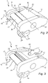
- shows in perspective view an embodiment of the cam buckle with the locking element in the closed position.
- Fig. 3
- shows in perspective view an embodiment of the cam buckle with the locking element in the closed position.
- Fig. 4
- shows in perspective view an embodiment of the cam buckle with the locking element in the open position.
- Fig. 5
- shows in perspective view the locking element according to an embodiment of the cam buckle.
- Fig. 6
- shows in perspective view an alternative embodiment of the cam buckle.
-
Figs. 1-4 show an embodiment of a cam buckle 1 for fastening a load strap according to an aspect of the present invention. The cam buckle 1 comprises apivotable cam 30 and acrossbar 21 forming part of a pivotablydisplaceable locking element 20. Thecam 30 andlocking element 20 are pivotably connected to aU-shaped buckle frame 10 which is made of twoparallel side arms second crossbar 11. The twoside arms second crossbar 11 transversally arranged between respective end portions of theside arms - The dimensions of the
buckle frame 10, such as the length, width and thickness of theside arms second crossbar 11, as well as the dimensions of thelocking element 20 and of thecam 30, may be chosen to best fit an intended size of a load strap to be used and the anticipated load to withstand. For example, the cam buckle may be sized to accommodate a load strap of 25 mm, 35 mm, 45 mm or 50 mm in width. Thebuckle frame 10,locking element 20 andcam 30 may for example be made of a metallic material or hard plastic. The buckle frame may be manufactured as a single piece, for example by casting or moulding, or by joining separatly manufacturedside arms second crossbar 11, for example by welding. - With reference to
Figs. 2 and 3 , thecam 30 is pivotably connected to generally medial portions of theside arms crossbars side arms cam 30 is pivotable between a clamping position, shown inFig. 2 , and a release position, shown inFig. 3 . On one side of its pivot axis A, thecam 30 has a grippingportion 32, shown inFig. 3 . A biasingelement 34, connected to thebuckle frame 10 and to thecam 30, biases thecam 30 towards its clamping position, in which the grippingportion 32 is pushed against thecrossbar 21. The grippingportion 32 of thecam 30 has a serrated structure formed by a plurality of parallel teeth extending along the grippingportion 32, parallel to the pivot axis A of thecam 30. Alternatively, the surface of the grippingportion 32 could for example be knurled. On the other side of its pivot axis A, thecam 30 has an actuatingportion 33, configured to be pressed by a user to push the cam into its release position. - The locking
element 20 is arranged with thecrossbar 21 extending between theside arms side arms second crossbar 11. The lockingelement 20 has anattachment arm 24 extending perpendicular to thecrossbar 21 between an end portion of thecrossbar 21 and anattachment portion 25. The locking element is pivotably connected to oneside arm 12 at theattachment portion 25, with a pivot axis B parallel to thecrossbar 21. The end portion of theside arm 13 opposite the end portion of theside arm 12 to which the locking element is connected has a chamferededge 16. - On the inside of each
side arm ledge side arm attachment portion 25 of the lockingelement 20 and thesecond crossbar 11. Closest to the lockingelement 20, theledge crossbar 21. - As shown in
Fig. 5 , theattachment arm 24 has a hook shape, creating atrough 28 aligned between the end portion of thecrossbar 21 and theattachment portion 25. InFigs. 2 and 3 , thetrough 28 accommodates part of theledge 14 that follows the contour of the end portion of thecrossbar 21. Further, theattachment portion 25 has twoprongs side arm 12 to which thelocking element 20 is connected. The lockingelement 20 may be connected to theside arm 12 by a riveted joint through the twoprongs side arm 12, or by any appropriate joint allowing the locking element to pivot. Theattachment portion 25 could alternatively comprise asingle prong 26. - As further shown in
Fig. 5 , thecrossbar 21 of the lockingelement 20 has an asymmetric cross-section, with a generallyflat portion 22. Theflat portion 22, Like the grippingportion 32 of thecam 30, thisflat portion 22 of thecrossbar 21 has a serrated structure formed by a plurality of parallel teeth extending along thecrossbar 21 between end portions of thecrossbar 21. In the cam buckle 1 as shown inFig. 2 , theflat portion 22 of the lockingelement 20 and the grippingportion 32 of thecam 30 are facing each other (and thus not visible inFig. 2 ). The end portion of thecrossbar 21 opposite theattachment arm 24 has anend cap 23. - The cam buckle 1 as shown in
Figs. 2 and 3 may be used as a traditional cam buckle. The actuatingportion 33 of thecam 30 is pushed on by a finger of a user, in order to pivot thecam 30 toward its release position, as shown inFig. 3 . With thecam 30 in the release position, there is a clearance between the gripingportion 32 and thecrossbar 21. An end of a load strap may be inserted into this clearance and be freely moved. When the user releases the pressure on the actuatingportion 33, thecam 30 returns to its clamping position thanks to the biasingelement 34, and sandwiches the load strap between the grippingportion 32 and thecrossbar 21. The load strap is then pulled through the cam buckle 1 until the slack in the strap is removed and a desired tension is created. The end of the load strap is inserted in the cam buckle 1 such that the pulling on the strap to remove slack occurs in a direction going from the clamping position to the release position of thecam 30. The tension in the strap pulls the grippingportion 32 of thecam 30 toward thecrossbar 21, thus increasing the clamping force on the strap, securing it in place. - The locking
element 20 is pivotable between a closed position, shown inFigs. 2 and 3 , and an open position, shown inFig. 4 . When the lockingelement 20 is in the open position shown inFig. 4 , an opening is created between thecrossbar 21 and one of theside arms 13. The opening allows aload strap 40 to be inserted laterally as illustrated by the arrow inFig. 4 . The chamferededge 16 of theside arm 13 increases this opening, facilitating the insertion of theload strap 40. Subsequently, the lockingelement 20 is pushed back toward the closed position seen inFig. 2 , leaving theload strap 40 constrained laterally between theside arms crossbar 21 and thecam 30, respectively. - The
ledge element 20 when the locking element is in the closed position. Theledge element 20 from further pivoting about axis B once the lockingelement 20 has reached its closed position, when pivoting from the open position to the closed position of the lockingelement 20. Conversely, when the lockingelement 20 is in the closed position, thecam 30 restricts the lockingelement 20 from pivoting back about axis B toward the open position, as long as thecam 30 is in the clamping position shown inFig. 2 . - In other words, the locking
element 20 in the closed position is locked in place by theledge cam 30 in clamping position on the other side, albeit with some clearance between thecrossbar 21 and thecam 30 to accommodate a load strap therebetween. When the actuating portion of thecam 30 is pushed and thecam 30 pivots to its release position, as shown inFig. 3 , the lockingelement 20 is allowed to pivot from its closed position to its open position. In so doing, thecrossbar 21 follows a path going first inward, toward the middle of the buckle 1, and away from theledge crossbar 21 and theside arm 13 opposite theside arm 12 to which thelocking element 20 is connected. Displacing the lockingelement 20 from the open position to the closed position only requires puching on the crossbar 21 (or another part of the locking element 20) to pivot in the other direction. When thecrossbar 21 comes into contact with thecam 30, it pushes thecam 30 to slightly pivot toward its realease position until the lockingelement 20 is free to reach the closed position. The biasing element ensures that thecam 30 directly returns to the clamping position after passage of thecrossbar 21. This quick movement of thecam 30 produces a click sound, indicating to the user that the lockingelement 20 is locked in place. - The
ledge crossbar 21 to the buckle frame 1. As a load strap in tension pulls on thecrossbar 21, the end portions of thecrossbar 21 engage with therespective ledge side arms buckle frame 10 and the lockingelement 21. -
Fig. 6 shows an alternative embodiment of thecam buckle 100. Thecam buckle 100 comprises apivotable cam 30 and a slidablydisplaceable locking element 120 forming acrossbar 121 connected to aU-shaped buckle frame 110. Thebuckle frame 110 is made of twoside arms second crossbar 111. The twoside arms second crossbar 111 transversally arranged between respective end portions of theside arms - The locking element is slidably displaceable between a closed position, in which the
crossbar 121 extends between the twoside arms crossbar 121 is separated from oneside arm 113, as shown inFig. 6 . The displacement of the locking element occurs along the main axis of thecrossbar 121, through an opening in theother side arm 112. - The
cam 30 is pivotably connected to generally medial portions of theside arms crossbars side arms cam 30 is pivotable between a clamping position and a release position. On one side of its pivot axis, thecam 30 has a grippingportion 32. A biasing element, connected to thebuckle frame 110 and to thecam 30, biases thecam 30 towards its clamping position, in which the grippingportion 32 is pushed against thecrossbar 121, when thecrossbar 121 is in the closed position of thelocking element 120. - When the
locking element 120 is in the closed position, thecam buckle 100 may be used as a traditional cam buckle, in the same way as the cam buckle 1 described inFigs. 2 and 3 . When thelocking element 120 is in the open position as shown inFig. 6 , an opening is created between thecrossbar 121 and one of theside arms 113. The opening allows a load strap to be inserted in thecam buckle 100 without having to thread an end of the load strap between thecrossbar 121 and thecam 30. The lockingelement 120 is subsequently returned to its closed position, leaving the load strap constrained laterally between theside arms crossbar 121 and thecam 30, respectively. - The skilled person in the art realizes that the present invention by no means is limited to the embodiments described above. The features of the described embodiments may be combined in different ways, and many modifications and variations are possible within the scope of the appended claims. In the claims, any reference signs placed in parentheses shall not be construed as limiting to the claim. The word "comprising" does not exclude the presence of other elements than those listed in the claim. The word "a" or "an" preceding an element does not exclude the presence of a plurality of such elements.
Claims (5)
- A buckle (1) for fastening a load strap (40), comprising:a buckle frame (10) having two substantially parallel side arms (12, 13),a crossbar (21) extending between said side arms (12, 13) along a main axis, the main axis being substantially perpendicular to the side arms (12,13),a cam (30) arranged between the side arms (12, 13), the cam (30) being pivotable between a clamping position, in which a load strap (40) inserted between a gripping portion (32) of the cam and the crossbar (21) is clamped, and a release position, in which a clearance between the gripping portion (32) and the crossbar (21) is increased,characterized in thatthe crossbar (21) forms part of a locking element (20), which is displaceable between a closed position, in which the crossbar (21) extends between the side arms (12, 13) such that a load strap (40) positioned between the cam (30) and the crossbar (21) is laterally constrained by the side arms (12, 13), and an open position, in which the crossbar (21) is separated from at least one of the side arms (12, 13), such that a load strap (40) is laterally insertable between the cam (30) and the crossbar (21), andthe locking element (20) is displaceable such that the main axis of the crossbar (21) remains perpendicular to the side arms (12, 13) during a displacement between the closed position and the open position of the locking element (20), andthe locking element (20) is pivotably connected to a side arm (12) and pivotably displaceable between the closed position and the open position of the locking element (20).
- The buckle (1) according to claim 1, wherein the locking element (20) further comprises an attachment arm (24) extending between an end portion of the crossbar and an attachment portion (25) pivotably connected to a side arm (12) of the buckle frame (10), such that the pivot axis of the locking element (20) is parallel to but offset with respect to the main axis of the crossbar (21).
- The buckle (1) according to any one of the preceding claims, wherein each side arm (12, 13) comprises an abutment (14, 15) adapted to engage a respective end portion of the crossbar (21), in the closed position of the locking element (20), and wherein the locking element (20) is locked in the closed position by the cam (30) when the cam (30) is in the clamping position.
- The buckle (1) according to any one of the preceding claims, further comprising a biasing element (34), biasing the cam (30) toward the clamping position.
- The buckle (1) according to any one of the preceding claims, wherein the buckle frame (10) further comprises a second crossbar (11) fixedly connecting the side arms (12, 13) of the buckle frame (10), the second crossbar (11) forming an anchor for attaching one end of a load strap (40).
Priority Applications (6)
| Application Number | Priority Date | Filing Date | Title |
|---|---|---|---|
| PL20200525.2T PL3981646T3 (en) | 2020-10-07 | 2020-10-07 | Cam buckle |
| EP20200525.2A EP3981646B1 (en) | 2020-10-07 | 2020-10-07 | Cam buckle |
| ES20200525T ES2943057T3 (en) | 2020-10-07 | 2020-10-07 | cam buckle |
| DK20200525.2T DK3981646T3 (en) | 2020-10-07 | 2020-10-07 | CAM TENSION |
| FIEP20200525.2T FI3981646T3 (en) | 2020-10-07 | 2020-10-07 | Cam buckle |
| US17/490,361 US11564455B2 (en) | 2020-10-07 | 2021-09-30 | Cam buckle |
Applications Claiming Priority (1)
| Application Number | Priority Date | Filing Date | Title |
|---|---|---|---|
| EP20200525.2A EP3981646B1 (en) | 2020-10-07 | 2020-10-07 | Cam buckle |
Publications (2)
| Publication Number | Publication Date |
|---|---|
| EP3981646A1 EP3981646A1 (en) | 2022-04-13 |
| EP3981646B1 true EP3981646B1 (en) | 2023-01-25 |
Family
ID=72801360
Family Applications (1)
| Application Number | Title | Priority Date | Filing Date |
|---|---|---|---|
| EP20200525.2A Active EP3981646B1 (en) | 2020-10-07 | 2020-10-07 | Cam buckle |
Country Status (6)
| Country | Link |
|---|---|
| US (1) | US11564455B2 (en) |
| EP (1) | EP3981646B1 (en) |
| DK (1) | DK3981646T3 (en) |
| ES (1) | ES2943057T3 (en) |
| FI (1) | FI3981646T3 (en) |
| PL (1) | PL3981646T3 (en) |
Families Citing this family (2)
| Publication number | Priority date | Publication date | Assignee | Title |
|---|---|---|---|---|
| US20230346082A1 (en) * | 2020-11-11 | 2023-11-02 | Nite Ize, Inc. | Systems and methods for an improved capture area in association with a ratcheting device including pivoting tooth |
| USD996336S1 (en) * | 2021-02-24 | 2023-08-22 | Tian Wang | ATV windshield buckle |
Family Cites Families (5)
| Publication number | Priority date | Publication date | Assignee | Title |
|---|---|---|---|---|
| JPS62224305A (en) * | 1986-03-25 | 1987-10-02 | シチズン時計株式会社 | Tail lock structure of band |
| US8191208B2 (en) * | 2008-06-06 | 2012-06-05 | Hanson Burton W | Load securing ratchet with anchor attachment system |
| FI125037B (en) | 2013-03-27 | 2015-04-30 | Esa Takkinen | Device and system for securing a load line |
| NL2013670B1 (en) * | 2014-10-23 | 2016-10-05 | Slim Gevonden B V | Coupler for coupling a substantially elongated belt portion, coupler assembly and coupling method. |
| US9526301B1 (en) * | 2015-06-10 | 2016-12-27 | Jill Sloan | Adaptable buckle system |
-
2020
- 2020-10-07 EP EP20200525.2A patent/EP3981646B1/en active Active
- 2020-10-07 PL PL20200525.2T patent/PL3981646T3/en unknown
- 2020-10-07 DK DK20200525.2T patent/DK3981646T3/en active
- 2020-10-07 FI FIEP20200525.2T patent/FI3981646T3/en active
- 2020-10-07 ES ES20200525T patent/ES2943057T3/en active Active
-
2021
- 2021-09-30 US US17/490,361 patent/US11564455B2/en active Active
Also Published As
| Publication number | Publication date |
|---|---|
| US20220104589A1 (en) | 2022-04-07 |
| ES2943057T3 (en) | 2023-06-08 |
| FI3981646T3 (en) | 2023-05-03 |
| EP3981646A1 (en) | 2022-04-13 |
| DK3981646T3 (en) | 2023-04-24 |
| PL3981646T3 (en) | 2023-05-29 |
| US11564455B2 (en) | 2023-01-31 |
Similar Documents
| Publication | Publication Date | Title |
|---|---|---|
| CN100564181C (en) | High Performance Cable Ties | |
| EP2280881B1 (en) | Tightenable clamping device, suitable for application in tie wrap | |
| US11564455B2 (en) | Cam buckle | |
| US7992267B2 (en) | Snap lock carabiner | |
| CA2283423C (en) | In-line cable tie | |
| EP3050819B1 (en) | Binding band securing structure and binding tool | |
| CA2395023A1 (en) | End-fitting webbing buckle | |
| US10194917B1 (en) | Tourniquet with lever tensioning mechanism | |
| US7051410B2 (en) | Snap hook with two opposed closing figures | |
| CN104487351A (en) | Manual bundling tool | |
| EP0235997A1 (en) | Cable tie | |
| EP0263835A1 (en) | Buckle type fastener | |
| US3761999A (en) | Cable strap with multiple tooth pawl | |
| JP2004313268A (en) | buckle | |
| CN101024435A (en) | Buckle with safety device | |
| CA2824999A1 (en) | Self-locking clip systems and methods | |
| CN101835396A (en) | Clamping mechanism for clamping device | |
| US6401310B1 (en) | Snowshoe buckle | |
| EP1956934B1 (en) | Belt and buckle for a belt | |
| US8256067B2 (en) | Buckle, and an assembly comprising a belt and a buckle | |
| KR101496259B1 (en) | Tool for cable tie | |
| JPH0744838Y2 (en) | Belt fastening | |
| US12509176B2 (en) | Latch mechanism | |
| JPH09289906A (en) | End part holder | |
| US12478144B2 (en) | Holder for connecting a neck strap to the helmet shell of a helmet |
Legal Events
| Date | Code | Title | Description |
|---|---|---|---|
| PUAI | Public reference made under article 153(3) epc to a published international application that has entered the european phase |
Free format text: ORIGINAL CODE: 0009012 |
|
| STAA | Information on the status of an ep patent application or granted ep patent |
Free format text: STATUS: REQUEST FOR EXAMINATION WAS MADE |
|
| 17P | Request for examination filed |
Effective date: 20210323 |
|
| AK | Designated contracting states |
Kind code of ref document: A1 Designated state(s): AL AT BE BG CH CY CZ DE DK EE ES FI FR GB GR HR HU IE IS IT LI LT LU LV MC MK MT NL NO PL PT RO RS SE SI SK SM TR |
|
| GRAP | Despatch of communication of intention to grant a patent |
Free format text: ORIGINAL CODE: EPIDOSNIGR1 |
|
| STAA | Information on the status of an ep patent application or granted ep patent |
Free format text: STATUS: GRANT OF PATENT IS INTENDED |
|
| INTG | Intention to grant announced |
Effective date: 20220825 |
|
| GRAS | Grant fee paid |
Free format text: ORIGINAL CODE: EPIDOSNIGR3 |
|
| GRAA | (expected) grant |
Free format text: ORIGINAL CODE: 0009210 |
|
| STAA | Information on the status of an ep patent application or granted ep patent |
Free format text: STATUS: THE PATENT HAS BEEN GRANTED |
|
| AK | Designated contracting states |
Kind code of ref document: B1 Designated state(s): AL AT BE BG CH CY CZ DE DK EE ES FI FR GB GR HR HU IE IS IT LI LT LU LV MC MK MT NL NO PL PT RO RS SE SI SK SM TR |
|
| REG | Reference to a national code |
Ref country code: GB Ref legal event code: FG4D |
|
| REG | Reference to a national code |
Ref country code: CH Ref legal event code: EP |
|
| REG | Reference to a national code |
Ref country code: DE Ref legal event code: R096 Ref document number: 602020007815 Country of ref document: DE |
|
| REG | Reference to a national code |
Ref country code: AT Ref legal event code: REF Ref document number: 1545698 Country of ref document: AT Kind code of ref document: T Effective date: 20230215 Ref country code: IE Ref legal event code: FG4D |
|
| REG | Reference to a national code |
Ref country code: DK Ref legal event code: T3 Effective date: 20230421 |
|
| REG | Reference to a national code |
Ref country code: SE Ref legal event code: TRGR |
|
| REG | Reference to a national code |
Ref country code: LT Ref legal event code: MG9D |
|
| REG | Reference to a national code |
Ref country code: NL Ref legal event code: MP Effective date: 20230125 |
|
| REG | Reference to a national code |
Ref country code: ES Ref legal event code: FG2A Ref document number: 2943057 Country of ref document: ES Kind code of ref document: T3 Effective date: 20230608 |
|
| REG | Reference to a national code |
Ref country code: NO Ref legal event code: T2 Effective date: 20230125 |
|
| REG | Reference to a national code |
Ref country code: AT Ref legal event code: MK05 Ref document number: 1545698 Country of ref document: AT Kind code of ref document: T Effective date: 20230125 |
|
| PG25 | Lapsed in a contracting state [announced via postgrant information from national office to epo] |
Ref country code: NL Free format text: LAPSE BECAUSE OF FAILURE TO SUBMIT A TRANSLATION OF THE DESCRIPTION OR TO PAY THE FEE WITHIN THE PRESCRIBED TIME-LIMIT Effective date: 20230125 |
|
| P01 | Opt-out of the competence of the unified patent court (upc) registered |
Effective date: 20230524 |
|
| PG25 | Lapsed in a contracting state [announced via postgrant information from national office to epo] |
Ref country code: RS Free format text: LAPSE BECAUSE OF FAILURE TO SUBMIT A TRANSLATION OF THE DESCRIPTION OR TO PAY THE FEE WITHIN THE PRESCRIBED TIME-LIMIT Effective date: 20230125 Ref country code: PT Free format text: LAPSE BECAUSE OF FAILURE TO SUBMIT A TRANSLATION OF THE DESCRIPTION OR TO PAY THE FEE WITHIN THE PRESCRIBED TIME-LIMIT Effective date: 20230525 Ref country code: LV Free format text: LAPSE BECAUSE OF FAILURE TO SUBMIT A TRANSLATION OF THE DESCRIPTION OR TO PAY THE FEE WITHIN THE PRESCRIBED TIME-LIMIT Effective date: 20230125 Ref country code: LT Free format text: LAPSE BECAUSE OF FAILURE TO SUBMIT A TRANSLATION OF THE DESCRIPTION OR TO PAY THE FEE WITHIN THE PRESCRIBED TIME-LIMIT Effective date: 20230125 Ref country code: HR Free format text: LAPSE BECAUSE OF FAILURE TO SUBMIT A TRANSLATION OF THE DESCRIPTION OR TO PAY THE FEE WITHIN THE PRESCRIBED TIME-LIMIT Effective date: 20230125 Ref country code: AT Free format text: LAPSE BECAUSE OF FAILURE TO SUBMIT A TRANSLATION OF THE DESCRIPTION OR TO PAY THE FEE WITHIN THE PRESCRIBED TIME-LIMIT Effective date: 20230125 |
|
| PG25 | Lapsed in a contracting state [announced via postgrant information from national office to epo] |
Ref country code: IS Free format text: LAPSE BECAUSE OF FAILURE TO SUBMIT A TRANSLATION OF THE DESCRIPTION OR TO PAY THE FEE WITHIN THE PRESCRIBED TIME-LIMIT Effective date: 20230525 Ref country code: GR Free format text: LAPSE BECAUSE OF FAILURE TO SUBMIT A TRANSLATION OF THE DESCRIPTION OR TO PAY THE FEE WITHIN THE PRESCRIBED TIME-LIMIT Effective date: 20230426 |
|
| REG | Reference to a national code |
Ref country code: DE Ref legal event code: R097 Ref document number: 602020007815 Country of ref document: DE |
|
| PG25 | Lapsed in a contracting state [announced via postgrant information from national office to epo] |
Ref country code: SM Free format text: LAPSE BECAUSE OF FAILURE TO SUBMIT A TRANSLATION OF THE DESCRIPTION OR TO PAY THE FEE WITHIN THE PRESCRIBED TIME-LIMIT Effective date: 20230125 Ref country code: RO Free format text: LAPSE BECAUSE OF FAILURE TO SUBMIT A TRANSLATION OF THE DESCRIPTION OR TO PAY THE FEE WITHIN THE PRESCRIBED TIME-LIMIT Effective date: 20230125 Ref country code: EE Free format text: LAPSE BECAUSE OF FAILURE TO SUBMIT A TRANSLATION OF THE DESCRIPTION OR TO PAY THE FEE WITHIN THE PRESCRIBED TIME-LIMIT Effective date: 20230125 Ref country code: CZ Free format text: LAPSE BECAUSE OF FAILURE TO SUBMIT A TRANSLATION OF THE DESCRIPTION OR TO PAY THE FEE WITHIN THE PRESCRIBED TIME-LIMIT Effective date: 20230125 |
|
| PG25 | Lapsed in a contracting state [announced via postgrant information from national office to epo] |
Ref country code: SK Free format text: LAPSE BECAUSE OF FAILURE TO SUBMIT A TRANSLATION OF THE DESCRIPTION OR TO PAY THE FEE WITHIN THE PRESCRIBED TIME-LIMIT Effective date: 20230125 |
|
| PLBE | No opposition filed within time limit |
Free format text: ORIGINAL CODE: 0009261 |
|
| STAA | Information on the status of an ep patent application or granted ep patent |
Free format text: STATUS: NO OPPOSITION FILED WITHIN TIME LIMIT |
|
| 26N | No opposition filed |
Effective date: 20231026 |
|
| PG25 | Lapsed in a contracting state [announced via postgrant information from national office to epo] |
Ref country code: SI Free format text: LAPSE BECAUSE OF FAILURE TO SUBMIT A TRANSLATION OF THE DESCRIPTION OR TO PAY THE FEE WITHIN THE PRESCRIBED TIME-LIMIT Effective date: 20230125 |
|
| PG25 | Lapsed in a contracting state [announced via postgrant information from national office to epo] |
Ref country code: IT Free format text: LAPSE BECAUSE OF FAILURE TO SUBMIT A TRANSLATION OF THE DESCRIPTION OR TO PAY THE FEE WITHIN THE PRESCRIBED TIME-LIMIT Effective date: 20230125 Ref country code: MC Free format text: LAPSE BECAUSE OF FAILURE TO SUBMIT A TRANSLATION OF THE DESCRIPTION OR TO PAY THE FEE WITHIN THE PRESCRIBED TIME-LIMIT Effective date: 20230125 |
|
| REG | Reference to a national code |
Ref country code: CH Ref legal event code: PL |
|
| REG | Reference to a national code |
Ref country code: BE Ref legal event code: MM Effective date: 20231031 |
|
| PG25 | Lapsed in a contracting state [announced via postgrant information from national office to epo] |
Ref country code: LU Free format text: LAPSE BECAUSE OF NON-PAYMENT OF DUE FEES Effective date: 20231007 |
|
| PG25 | Lapsed in a contracting state [announced via postgrant information from national office to epo] |
Ref country code: LU Free format text: LAPSE BECAUSE OF NON-PAYMENT OF DUE FEES Effective date: 20231007 |
|
| PG25 | Lapsed in a contracting state [announced via postgrant information from national office to epo] |
Ref country code: CH Free format text: LAPSE BECAUSE OF NON-PAYMENT OF DUE FEES Effective date: 20231031 |
|
| PG25 | Lapsed in a contracting state [announced via postgrant information from national office to epo] |
Ref country code: CH Free format text: LAPSE BECAUSE OF NON-PAYMENT OF DUE FEES Effective date: 20231031 |
|
| PG25 | Lapsed in a contracting state [announced via postgrant information from national office to epo] |
Ref country code: BE Free format text: LAPSE BECAUSE OF NON-PAYMENT OF DUE FEES Effective date: 20231031 |
|
| PG25 | Lapsed in a contracting state [announced via postgrant information from national office to epo] |
Ref country code: IE Free format text: LAPSE BECAUSE OF NON-PAYMENT OF DUE FEES Effective date: 20231007 |
|
| PG25 | Lapsed in a contracting state [announced via postgrant information from national office to epo] |
Ref country code: IE Free format text: LAPSE BECAUSE OF NON-PAYMENT OF DUE FEES Effective date: 20231007 |
|
| PG25 | Lapsed in a contracting state [announced via postgrant information from national office to epo] |
Ref country code: BG Free format text: LAPSE BECAUSE OF FAILURE TO SUBMIT A TRANSLATION OF THE DESCRIPTION OR TO PAY THE FEE WITHIN THE PRESCRIBED TIME-LIMIT Effective date: 20230125 |
|
| PG25 | Lapsed in a contracting state [announced via postgrant information from national office to epo] |
Ref country code: BG Free format text: LAPSE BECAUSE OF FAILURE TO SUBMIT A TRANSLATION OF THE DESCRIPTION OR TO PAY THE FEE WITHIN THE PRESCRIBED TIME-LIMIT Effective date: 20230125 |
|
| PG25 | Lapsed in a contracting state [announced via postgrant information from national office to epo] |
Ref country code: CY Free format text: LAPSE BECAUSE OF FAILURE TO SUBMIT A TRANSLATION OF THE DESCRIPTION OR TO PAY THE FEE WITHIN THE PRESCRIBED TIME-LIMIT; INVALID AB INITIO Effective date: 20201007 |
|
| PG25 | Lapsed in a contracting state [announced via postgrant information from national office to epo] |
Ref country code: HU Free format text: LAPSE BECAUSE OF FAILURE TO SUBMIT A TRANSLATION OF THE DESCRIPTION OR TO PAY THE FEE WITHIN THE PRESCRIBED TIME-LIMIT; INVALID AB INITIO Effective date: 20201007 |
|
| PGFP | Annual fee paid to national office [announced via postgrant information from national office to epo] |
Ref country code: DK Payment date: 20250916 Year of fee payment: 6 |
|
| PGFP | Annual fee paid to national office [announced via postgrant information from national office to epo] |
Ref country code: PL Payment date: 20250917 Year of fee payment: 6 |
|
| PG25 | Lapsed in a contracting state [announced via postgrant information from national office to epo] |
Ref country code: TR Free format text: LAPSE BECAUSE OF FAILURE TO SUBMIT A TRANSLATION OF THE DESCRIPTION OR TO PAY THE FEE WITHIN THE PRESCRIBED TIME-LIMIT Effective date: 20230125 |
|
| PGFP | Annual fee paid to national office [announced via postgrant information from national office to epo] |
Ref country code: DE Payment date: 20251010 Year of fee payment: 6 |
|
| PGFP | Annual fee paid to national office [announced via postgrant information from national office to epo] |
Ref country code: GB Payment date: 20251013 Year of fee payment: 6 |
|
| PGFP | Annual fee paid to national office [announced via postgrant information from national office to epo] |
Ref country code: NO Payment date: 20251013 Year of fee payment: 6 |
|
| PGFP | Annual fee paid to national office [announced via postgrant information from national office to epo] |
Ref country code: FI Payment date: 20251014 Year of fee payment: 6 |
|
| PGFP | Annual fee paid to national office [announced via postgrant information from national office to epo] |
Ref country code: FR Payment date: 20251014 Year of fee payment: 6 |
|
| PGFP | Annual fee paid to national office [announced via postgrant information from national office to epo] |
Ref country code: SE Payment date: 20251014 Year of fee payment: 6 |
|
| PGFP | Annual fee paid to national office [announced via postgrant information from national office to epo] |
Ref country code: ES Payment date: 20260108 Year of fee payment: 6 |