EP3981585A1 - Apparatus and method for manufacturing of spiral tubes having at least two layers - Google Patents
Apparatus and method for manufacturing of spiral tubes having at least two layers Download PDFInfo
- Publication number
- EP3981585A1 EP3981585A1 EP20201335.5A EP20201335A EP3981585A1 EP 3981585 A1 EP3981585 A1 EP 3981585A1 EP 20201335 A EP20201335 A EP 20201335A EP 3981585 A1 EP3981585 A1 EP 3981585A1
- Authority
- EP
- European Patent Office
- Prior art keywords
- strand
- unit
- tension
- identifying
- point
- Prior art date
- Legal status (The legal status is an assumption and is not a legal conclusion. Google has not performed a legal analysis and makes no representation as to the accuracy of the status listed.)
- Withdrawn
Links
Images


Classifications
-
- B—PERFORMING OPERATIONS; TRANSPORTING
- B31—MAKING ARTICLES OF PAPER, CARDBOARD OR MATERIAL WORKED IN A MANNER ANALOGOUS TO PAPER; WORKING PAPER, CARDBOARD OR MATERIAL WORKED IN A MANNER ANALOGOUS TO PAPER
- B31C—MAKING WOUND ARTICLES, e.g. WOUND TUBES, OF PAPER, CARDBOARD OR MATERIAL WORKED IN A MANNER ANALOGOUS TO PAPER
- B31C3/00—Making tubes or pipes by feeding obliquely to the winding mandrel centre line
-
- B—PERFORMING OPERATIONS; TRANSPORTING
- B31—MAKING ARTICLES OF PAPER, CARDBOARD OR MATERIAL WORKED IN A MANNER ANALOGOUS TO PAPER; WORKING PAPER, CARDBOARD OR MATERIAL WORKED IN A MANNER ANALOGOUS TO PAPER
- B31D—MAKING ARTICLES OF PAPER, CARDBOARD OR MATERIAL WORKED IN A MANNER ANALOGOUS TO PAPER, NOT PROVIDED FOR IN SUBCLASSES B31B OR B31C
- B31D5/00—Multiple-step processes for making three-dimensional [3D] articles
- B31D5/0095—Making drinking straws
-
- B—PERFORMING OPERATIONS; TRANSPORTING
- B65—CONVEYING; PACKING; STORING; HANDLING THIN OR FILAMENTARY MATERIAL
- B65H—HANDLING THIN OR FILAMENTARY MATERIAL, e.g. SHEETS, WEBS, CABLES
- B65H59/00—Adjusting or controlling tension in filamentary material, e.g. for preventing snarling; Applications of tension indicators
- B65H59/02—Adjusting or controlling tension in filamentary material, e.g. for preventing snarling; Applications of tension indicators by regulating delivery of material from supply package
Definitions
- the object of the invention is an apparatus and a method for manufacturing of spiral tubes having at least two layers.
- spiral tubes manufactured by winding at least two material strands, usually paper strands, are commonly used. Such tubes are used as straws for drinking of beverages or may also be used as one of filter elements in a smoking article.
- a problem which occurs during the spiral tube manufacturing process is breaking of the material strand, which results in machine stoppage, downtimes and decreased productivity.
- the material strand may break due to too big momentary tension or local weakening.
- Momentary increases in tension and breakages may occur, for example, when the machine is stopped or started. They also occur during the winding of the outer material strand on the forming rod around which the previous strand has been wound with a splice connecting the end of the strand from one roll with the beginning of the strand from the other roll, thus creating a thickening.
- a weakening of the material strand may also be a manufacturing defect, for example the strand may have a smaller thickness over a certain section, may be worn through or soaked through with glue or other liquid used in the manufacturing process.
- a very important aspect in the tube manufacturing process is to maintain such an adequate tension of the material strand which will not cause strand breaking and machine stopping.
- the tensioning device consists of three rollers situated one after another between which the material strand is wound. In order to increase the strand tension, the central roller is moved away from the other rollers, thus stretching the material strand and increasing its tension.
- a tape tensioning device consisting of two rollers whose axes of rotation are parallel to each other and between which the tape is wound.
- the rollers are attached to a rotating disc whose axis of rotation is also parallel to the axis of rotation of the rotating rollers.
- the disc is turned to the left or to the right, thus causing an alteration in the position of the rollers on which the tape is wound.
- Material strand tensioning devices are known from the state of the art, but none of them solves the problem of momentary change in the tension in order to prevent the strand from breaking, and depending on the occurring problem which may result in a breakage.
- the problem to be solved by this invention is to eliminate breaking of the material strand during the spiral tube forming process.
- the proposed apparatus and method according to the invention are based on a momentary change in the tension of the material strands (the bobbin), thus they solve the problem presented above.
- the object of the invention is an apparatus for manufacturing of spiral tubes having at least two layers, comprising: at least two feeding units for feeding material strands, a tensioner of the material strand, a forming unit comprising a forming rod and a forming strip that winds around a formed fragment of a continuous tube for forming the tube on the forming rod, and a cutting head for cutting an individual tube from the formed continuous tube.
- the apparatus is characterised by further comprising an identifying unit for identifying a point of deviated strand parameters and an adjusting unit adapted to alter the tension of at least one strand by means of the tensioner, in response to a signal identifying the point of deviated strand parameters generated by the identifying unit.
- the apparatus is characterised in that the identifying unit for identifying the point of deviated strand parameters is adapted to identify any point of strand joining, deviation in strand density, deviation in strand width, to identify any point where the strand is damaged, or to receive control signals, in particular a joining signal.
- the apparatus is characterised in that the identifying unit for identifying the point of deviated strand parameters is provided with a sensor for direct measurement of the strand parameters.
- the apparatus is characterised in that the identifying unit for identifying the point of deviated strand parameters is provided with a sensor for indirect measurement of the strand parameters.
- the apparatus is characterised in that the identifying unit for identifying the point of deviated strand parameters is adapted to identify the point of deviated parameters based on signals controlling the spiral tube manufacturing process, in particular of at least one joining unit for joining the material strands in the area of the material strand feeding unit.
- the apparatus is characterised in that the material strand is made of paper, aluminium, PLA, material of fibrous structure, biodegradable material, material of plant origin.
- the apparatus is characterised in that the adjusting unit is adapted to alter the tension of at least one strand in response to a signal identifying the point of deviated strand parameters generated by the identifying unit at a moment when the point of deviated strand parameters is within the area from the feeding unit to the forming unit, in particular in the area of the forming unit.
- the apparatus is characterised in that the adjusting unit is adapted to determine the moment of alteration in strand tension based on direct or indirect measurement of strand shift, or real-time simulation of the spiral tube manufacturing process.
- the apparatus is characterised in that the adjusting unit is adapted to generate and send to the tensioner a signal to alter the value of material strand tension by altering the value of force with which the tensioner acts on the material strand or by altering the value of pressure supplied to the tensioner.
- the apparatus is characterised in that the adjusting unit is adapted to generate a signal to momentarily alter the value of material strand tension, in particular at least for the time when the material strand is moved from the feeding unit to the cutting head.
- the object of the invention is also a method for manufacturing of spiral tubes having at least two layers, comprising steps wherein: at least two material strands are fed by means of a feeding unit to a forming unit, the material strands being kept in pre-tension, a continuous spiral tube is formed of at least two material strands in the forming unit, and the continuous spiral tube is cut into sections of a specified length by means of a cutting head.
- the method according to the invention is characterised in that a point of deviated strand parameters is identified by means of an identifying unit and that the tension of at least one strand (2, 3, 4) is altered by means of an adjusting unit connected with the tensioner, in response to a signal identifying the point of deviated strand parameters generated by the identifying unit.
- the method is characterised in that the value of the material strand tension is momentarily altered by means of the tensioner.
- the method is characterised in that the value of the material strand tension is altered at least for the time of moving the point of deviated material strand parameters from the feeding unit to the forming unit.
- the method is characterised in that the value of the material strand tension is altered by altering the value of pressure supplied to the tensioner, or by altering the value of the force applied on the material strand by means of the tensioner.
- the method is characterised in that the value of the material strand tension is altered in the range between 0.5 and 6 bar.
- An advantage of the solution according to the invention is eliminating the unfavourable phenomenon of material strand breaking during the spiral tube forming process. It allows avoiding undesired production machine stoppages and downtimes.
- Fig. 1 shows an apparatus 1 for manufacturing of spiral tubes T of three material strands 2, 3, 4, in a perspective view, the casings being removed.
- the material strand may be made of paper, aluminium, PLA, material of fibrous structure, biodegradable material, material of plant origin or other material which maintains a continuous structure allowing to form the tube.
- the material strands 2, 3, 4 are fed from feeding units 5, and their quantity corresponds to the number of material strands of which the spiral tube T is made.
- Two-layer and three-layer tubes are commonly used, but it is also possible to manufacture a tube of a greater number of material strands.
- the feeding units 5a, 5b, 5c for feeding the material strands 2, 3, 4 there are rollers 6 with wound material strands from which they are taken on a current basis to manufacture the tube, and reserve rollers 7 which are left on standby until the strand on the rollers 6 runs out and a joining device 8 joins the end of the strand from the ending roller 6 with the beginning of the strand from the reserve roller 7.
- the material strands 2, 3, 4 then pass through tensioners 9 adapted to maintain the pre-tension of the strands.
- the tensioners 9 keep the strands 2, 3, 4 in tension ranging between 0.5 and 6 bar in order to ensure that the manufacturing process runs properly. A lack of proper strand tension may cause problems in the tube manufacturing process, such as incorrect winding on a forming rod 11, incorrect glue path placing on the strand 2, 3, 4 or strand breaking.
- From the tensioner 9, the material strands 2, 3, 4 are moved to a forming unit 10 where a glue path is applied onto them in advance by means of glue nozzles 14.
- the number of nozzles 14 and glue paths depends on the structure of the spiral tube, in particular on the number of the strands.
- the material strands 2, 3, 4 are wound successively in layers around the forming rod 11 by means of a forming strip 12. After forming a continuous tube CT on the rod 11, it is moved towards its end where it then passes through a cutting head 13.
- the cutting head may have one or more rotary knives which cut the continuous tube CT into sections of a specified length and form a tube T.
- the already finished tubes T are then received by a conveyor from the machine and transferred for a further production process.
- a commonly used practice of joining an ending of a material strand with the beginning of a new strand is sticking a piece of double-sided adhesive tape 16 by the operator at the beginning of the new strand, as shown in Fig.2a .
- the joining device 8 presses the end 17 of the strand 2, 3, 4 against the beginning 18 of the strand 2a, 3a, 4a on which the adhesive tape was placed by the operator.
- Other methods of joining the strands are also possible, for example by pressing, as shown in Fig. 2b .
- the joining device 8 presses the end 17 of the strand 2, 3, 4 against the beginning 18 of the strand 2a, 3a, 4a.
- the pressing surface of the joining device 8 has notches which press, at the contact points, the strand 2, 3, 4 against the strand 2a, 3a, 4a.
- a pressing joint 19 formed in such a way causes that at this point the material strand is uneven and thicker than the material strand at a point where there is no such joint.
- Fig. 2a shows a method of joining the end of the material strand 2, 3, 4 with the beginning of the material strand 2a, 3a, 4a from the reserve roller 7 by means of the double-sided adhesive tape 16.
- the strand joint comes to the forming unit 10 where it is wound around the forming rod 11.
- the joining of material strands occurs on one of the inner strands 2 or 3 ( Fig.1 )
- winding them around the forming rod 11 on the last outer strand 4 there is a momentary increase in tension caused by an increase in the diameter around which it is wound.
- the increase in diameter is caused by the occurrence of strand joining.
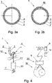
- Fig.3a shows a three-layer spiral tube T in a cross-section without a visible strand joining.
- the diameter of each of the wound strands 2, 3, 4 is uniform.
- Fig. 3b shows the three-layer spiral tube T in a cross-section with visible joining of the strand 2 by means of the adhesive tape 16.
- a deviation in the tube diameter having a significant impact on the wound outer strand 4 can be seen.
- This strand is subject to the greatest tensions so there is a risk of breaking the strand during the process.
- the smaller the diameter of the tube T the more likely it is that the outer material strand 4 will be unstuck at this point from the inner layer 3 and 2.
- Fig. 4 shows a simplified diagram of the apparatus for manufacturing of spiral tubes with a strand 4 tension adjusting unit in the first embodiment.
- the joining unit 8 sends a signal to the adjusting unit 14 which alters the value of strand 4 tension for the time until the joint on the strand 4 has been moved from the feeding unit 5c, and more precisely from the joining unit 8 to the exit of the forming unit 10.
- the adjusting unit 14 may have the form of a physical device which receives input signals and sends signals to other units of the device 1, for example as a controller, or it may have the form of an algorithm or a program stored in the apparatus 1.
- the time for which the tensioner 9 tensions the strand 4 with a reduced value is calculated on the basis of the speed of the apparatus 1 and the length of the strand section from the point where the joining occurred to the exit of the forming unit 10. It is also possible to measure the length of the strand section that needs to be moved from the point where the joining occurred to the exit of the forming unit 10.
- a servomotor driving the roller around which the material strand 4 is wound, an encoder or other device allowing to measure the length of the moved strand may be used.
- the tensioner 9 restores the initially set value of strand 4 tension.
- the adjusting unit 14 alters the strand 4 pre-tension value which is maintained by the tensioner 9 by altering the pressure which is supplied to the tensioner 9.
- the pre-tension of the strand 4 during the manufacturing process is maintained at a pressure supplied to the tensioner 9 ranging between 1.5 and 5 bar, whereas the pressure supplied to the tensioner 9 after the signal from the adjusting unit 14 is between 0.5 and 1 bar.
- the range of the pressure values is only an example and is largely dependent on the type of material of which the strand is made, the strand thickness, the strand width, the tube diameter, and the production speed.
- an identifying unit 20 may identify a point of deviated parameters of the strands 2, 3, 4 in a way that is known in the state of the art, for example by strand vision inspection, X-ray radiation, by means of ultrasonic signals, by means of proximity detectors, tension sensors.
- the identification of a point of deviated strand parameters may result from both direct measurement and indirect measurement.
- the identification of a point of deviated strand parameters may also result from an analysis of control signals appearing in the device because some deviations in the strand parameters are process deviations determined in time and space by the manufacturing process, e.g. strand joining, while other ones are random and require continuous monitoring of the strand parameters, e.g. a deviation in the density of the strand material.
- the unit 20 identifying the point of deviated strand 2, 3, 4 parameters generates a signal to the adjusting unit 14, whereas the identification of such points takes place in response to a signal commanding to join the strands or a signal confirming the joining of strands.
- the joining unit 8 fulfils the function of the identifying unit by sending the joining signal to the adjusting unit.
- the control signal sent to the joining unit 8 commanding to join the strands is also a signal identifying the joining point, thus the identifying unit 20 is such part of the device control system which attributes the meaning of identification of the point where the strand parameters are deviated to the process signals appearing in the device.
- the unit 20 identifying the point of deviated strand 2, 3, 4 parameters may, for example, identify the point of strand joining, deviation in strand density, deviation in strand width, the point where the strand is damaged, or where the control signals are received, in particular where a strand joining signal has been generated.
- the adjusting unit 14 may generate a strand 2, 3, 4 tension alteration signal immediately after identifying a point of deviated parameters, but it may also generate a tension alteration signal depending on other process parameters such as strand 2, 3, 4 length between the elements of the apparatus, the speed at which the production process takes place, at constant or variable interval.
- the adjusting unit 14 may generate the strand 2, 3, 4 tension alteration signal by means of computer modelling of the production process, e.g. with the use of FIFO (First In, First Out) shift registers, so that it is possible to track the current position of a point of deviated strand 2, 3, 4 parameters within the production process and generate appropriate signals on the basis of such process simulation.
- FIFO First In, First Out
- the adjusting unit 14 may generate a signal to reduce the tension as well as to increase the tension of the strand depending on the nature of the identified alteration in strand parameters, i.e. to alter the tension of at least one strand 2, 3, 4 by means of the tensioner in response to a signal identifying a point of deviated strand 2, 3, 4 parameters generated by the identifying unit 20.
- the adjusting unit 14 generates and sends to the tensioner 9 a signal of alteration in the strand 2, 3, 4 tension.
- An alteration in the strand 2, 3, 4 tension may occur at a moment when the point of deviated strand parameters is in the area from the feeding unit 5a, 5b, 5c to the forming unit 10, particularly in the area of the forming unit 10, or at least for the time of the movement of the material strand 2, 3, 4 from the feeding unit 5a, 5b, 5c to the cutting head 13.
- An alteration in the strand tension itself may, for example, be achieved by altering the force with which the tensioner 9 acts on the material strand 2, 3, 4 or by altering the value of pressure supplied to the tensioner 9.
- the most important feature is that the value of tension of the strand 4 is altered by the adjusting unit 14 until the joint occurring on the strand 4 comes off the forming rod 11 and is cut off by the cutting head 13 to form a tube T of a specified length.
- Such a tube with a joint may be treated as defective and may be rejected from the further production process.
- Fig. 5 shows a simplified diagram of the apparatus 1 for manufacturing of spiral tubes T with a strand 4 tension adjusting unit 14 in the second embodiment with a device 20 controlling the process parameters.
- the controlling device 20 in this embodiment is a camera situated between the tensioner 9 and the forming unit 10 in order to monitor the quality of the material strand 4. Examples of parameters that may be controlled are: density, homogeneity, temperature, thickness, and width of strand 4. The controlled process parameters may differ depending on the location of the controlling device 20 in the apparatus 1.
- the strand 4 is fed from the feeding unit 5c to the joining unit 8 in which the ending strand 4a is joined with the beginning of the new strand 4b.
- the strand 4 joined in such a way after leaving the joining unit 8, passes through the tensioner 9 in which it is pre-tensioned to a specified value and fed to the forming unit 10.
- the process parameter controlling device 20 in the form of a camera which checks the quality of the strand.
- a signal which alters the strand tension value on the tensioner 9.
- the tension value is temporarily reduced until the strand 4 joint is outside the forming rod 11 already in the form of a formed tube CT. After the strand 4 joint leaves the forming rod 11, the tension returns to the pre-set value.
- the process parameter controlling device 20 may also be situated near the glue nozzle 21, as shown in Fig. 6 .
- the process parameter controlling device 20 is a sensor monitoring the amount of glue applied onto the material strand 4.
- the device 20 sends a signal to the adjusting unit 14 which reduces the tension value of the strand 4 on the tensioner 9.
- the tension value after the reduction allows forming the tube T without the risk of strand breaking.
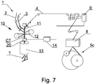
- the process parameter controlling device 20 may also be a microwave sensor, as shown in Fig. 7 in the next embodiment of the apparatus 1.
- the process parameter controlling device 20 may also be a microwave sensor, as shown in Fig. 7 in the next embodiment of the apparatus 1.
- the process parameter controlling device 20 is important to monitor many factors which affect the tube quality.
- the strand 2, 3, 4 gluing quality may be checked only after it has been formed in the forming unit 10. Therefore, beneath the place where the forming rod 11 ends, there is situated the process parameter controlling device 20 in the form of a microwave sensor which controls the quality of the manufactured tube CT online. If any irregularity in the tube forming is detected, the device 20 sends a signal to the adjusting unit 14, and then, after receiving the signal, the adjusting unit 14 alters the value of strand 4 tension until the quality of the manufactured tube CT is improved.
- the process parameter controlling device 20 may also have the form of other sensors which monitor the quality of the tube CT and T, not mentioned in the above embodiments, for example infrared sensor, X-ray sensor, or ultrasonic sensor.
- the principle of operation will be the same. It will send a signal to the adjusting unit 14 which will then alter the strand 2, 3, 4 tension by means of the tensioner 9. The time for which the tension value will be altered may differ depending on the parameter which is controlled by the sensor.
Landscapes
- Making Paper Articles (AREA)
Abstract
The object of the application is an apparatus for manufacturing of spiral tubes (T) having at least two layers, comprising: at least two feeding units (5a, 5b, 5c) for feeding material strands (2, 3, 4), a tensioner (9) of the material strand (2, 3, 4), a forming unit (10) comprising a forming rod (11) and a forming strip (12) that winds a formed fragment of a continuous tube (CT) for forming the tube on the forming rod (11), and a cutting head (13) for cutting an individual tube (T) from the formed continuous tube (CT). The apparatus is characterised by further comprising an identifying unit (20) for identifying a point of deviated strand (2, 3, 4) parameters and an adjusting unit (14) adapted to alter the tension of at least one strand (2, 3, 4) by means of the tensioner (9), in response to a signal identifying the point of deviated strand (2, 3, 4) parameters generated by the identifying unit (20). The object of the application is also a method for manufacturing of spiral tubes (T) having at least two layers.
Description
- The object of the invention is an apparatus and a method for manufacturing of spiral tubes having at least two layers.
- In the food industry, spiral tubes manufactured by winding at least two material strands, usually paper strands, are commonly used. Such tubes are used as straws for drinking of beverages or may also be used as one of filter elements in a smoking article.
- During the spiral tube production process it is important that the material strands, when wound around a forming rod, overlap to form at least two layers and that the edges of the strands are evenly wound so that there are no gaps between the strands or unstuck edges of the strands.
- Therefore, a very important factor in the process of manufacturing of spiral tubes is to maintain an adequate tension of the material strands, starting from the roller from which the material strand is fed up to the forming rod around which it is wound and a multilayer tube is formed.
- A problem which occurs during the spiral tube manufacturing process is breaking of the material strand, which results in machine stoppage, downtimes and decreased productivity. The material strand may break due to too big momentary tension or local weakening.
- Momentary increases in tension and breakages may occur, for example, when the machine is stopped or started. They also occur during the winding of the outer material strand on the forming rod around which the previous strand has been wound with a splice connecting the end of the strand from one roll with the beginning of the strand from the other roll, thus creating a thickening.
- A weakening of the material strand may also be a manufacturing defect, for example the strand may have a smaller thickness over a certain section, may be worn through or soaked through with glue or other liquid used in the manufacturing process.
- A very important aspect in the tube manufacturing process is to maintain such an adequate tension of the material strand which will not cause strand breaking and machine stopping.
- In the state of the art, machines for manufacturing of spiral tubes are known in which an apparatus for maintaining a constant tension of the material strands is used.
- In the document
US 1 252 284 , there is disclosed a machine for manufacturing of spiral tubes from material strands using an apparatus that puts tension on each strand independently. The apparatus for maintaining the pre-tension of the strands comprises elastic plates that apply pressure with a sufficient force on the surface of each strand. The tension level is adjusted individually for each strand by means of adjusting screws which increase or decrease the pressure of the plate on the strand. - In the document
US 2 128 564 , there is disclosed a machine for manufacturing of spiral tubes in which the material strands are kept in constant tension by a tensioning device. The material strand tensioning device consists of two flat elements between which the material strand is moved. In order to create the tension of the strand, the two flat elements are pressed against each other and simultaneously the friction on the material strand and the desired constant tension are generated. - In the
US , a device for pre-tensioning of a material strand in a machine for manufacturing of paper spiral tubes is presented. The tensioning device consists of three rollers situated one after another between which the material strand is wound. In order to increase the strand tension, the central roller is moved away from the other rollers, thus stretching the material strand and increasing its tension.patent 6 394 385 - In the document
US 3 556 904 , there is disclosed a tape tensioning device consisting of two rollers whose axes of rotation are parallel to each other and between which the tape is wound. The rollers are attached to a rotating disc whose axis of rotation is also parallel to the axis of rotation of the rotating rollers. In order to increase or decrease the tape tension, the disc is turned to the left or to the right, thus causing an alteration in the position of the rollers on which the tape is wound. - Material strand tensioning devices are known from the state of the art, but none of them solves the problem of momentary change in the tension in order to prevent the strand from breaking, and depending on the occurring problem which may result in a breakage.
- The problem to be solved by this invention is to eliminate breaking of the material strand during the spiral tube forming process. The proposed apparatus and method according to the invention are based on a momentary change in the tension of the material strands (the bobbin), thus they solve the problem presented above.
- The object of the invention is an apparatus for manufacturing of spiral tubes having at least two layers, comprising: at least two feeding units for feeding material strands, a tensioner of the material strand, a forming unit comprising a forming rod and a forming strip that winds around a formed fragment of a continuous tube for forming the tube on the forming rod, and a cutting head for cutting an individual tube from the formed continuous tube. The apparatus is characterised by further comprising an identifying unit for identifying a point of deviated strand parameters and an adjusting unit adapted to alter the tension of at least one strand by means of the tensioner, in response to a signal identifying the point of deviated strand parameters generated by the identifying unit.
- Preferably, the apparatus is characterised in that the identifying unit for identifying the point of deviated strand parameters is adapted to identify any point of strand joining, deviation in strand density, deviation in strand width, to identify any point where the strand is damaged, or to receive control signals, in particular a joining signal.
- Preferably, the apparatus is characterised in that the identifying unit for identifying the point of deviated strand parameters is provided with a sensor for direct measurement of the strand parameters.
- Preferably, the apparatus is characterised in that the identifying unit for identifying the point of deviated strand parameters is provided with a sensor for indirect measurement of the strand parameters.
- Preferably, the apparatus is characterised in that the identifying unit for identifying the point of deviated strand parameters is adapted to identify the point of deviated parameters based on signals controlling the spiral tube manufacturing process, in particular of at least one joining unit for joining the material strands in the area of the material strand feeding unit.
- Preferably, the apparatus is characterised in that the material strand is made of paper, aluminium, PLA, material of fibrous structure, biodegradable material, material of plant origin.
- Preferably, the apparatus is characterised in that the adjusting unit is adapted to alter the tension of at least one strand in response to a signal identifying the point of deviated strand parameters generated by the identifying unit at a moment when the point of deviated strand parameters is within the area from the feeding unit to the forming unit, in particular in the area of the forming unit.
- Preferably, the apparatus is characterised in that the adjusting unit is adapted to determine the moment of alteration in strand tension based on direct or indirect measurement of strand shift, or real-time simulation of the spiral tube manufacturing process.
- Preferably, the apparatus is characterised in that the adjusting unit is adapted to generate and send to the tensioner a signal to alter the value of material strand tension by altering the value of force with which the tensioner acts on the material strand or by altering the value of pressure supplied to the tensioner.
- Preferably, the apparatus is characterised in that the adjusting unit is adapted to generate a signal to momentarily alter the value of material strand tension, in particular at least for the time when the material strand is moved from the feeding unit to the cutting head.
- The object of the invention is also a method for manufacturing of spiral tubes having at least two layers, comprising steps wherein: at least two material strands are fed by means of a feeding unit to a forming unit, the material strands being kept in pre-tension, a continuous spiral tube is formed of at least two material strands in the forming unit, and the continuous spiral tube is cut into sections of a specified length by means of a cutting head. The method according to the invention is characterised in that a point of deviated strand parameters is identified by means of an identifying unit and that the tension of at least one strand (2, 3, 4) is altered by means of an adjusting unit connected with the tensioner, in response to a signal identifying the point of deviated strand parameters generated by the identifying unit.
- Preferably, the method is characterised in that the value of the material strand tension is momentarily altered by means of the tensioner.
- Preferably, the method is characterised in that the value of the material strand tension is altered at least for the time of moving the point of deviated material strand parameters from the feeding unit to the forming unit.
- Preferably, the method is characterised in that the value of the material strand tension is altered by altering the value of pressure supplied to the tensioner, or by altering the value of the force applied on the material strand by means of the tensioner.
- Preferably, the method is characterised in that the value of the material strand tension is altered in the range between 0.5 and 6 bar.
- An advantage of the solution according to the invention is eliminating the unfavourable phenomenon of material strand breaking during the spiral tube forming process. It allows avoiding undesired production machine stoppages and downtimes.
- The object of the invention is presented in more detail in a preferred embodiment in a drawing in which:
-
Fig. 1 shows an apparatus for manufacturing of spiral tubes having at least two layers in a perspective view; -
Fig. 2a shows the joining of two material strands by means of a piece of double-sided adhesive tape; -
Fig. 2b shows the joining of two material strands with the use of perforation; -
Fig. 3a shows a cross-section through a three-layer spiral tube; -
Fig. 3b shows a cross-section through the three-layer spiral tube with visible joining of the material strands by means of the adhesive tape; -
Fig. 4 shows a simplified diagram of the apparatus for manufacturing of spiral tubes with a strand tension adjusting unit in the first embodiment; -
Fig. 5 shows a simplified diagram of the apparatus for manufacturing of spiral tubes with the strand tension adjusting unit in the second embodiment; -
Fig. 6 shows a simplified diagram of the apparatus for manufacturing of spiral tubes with the strand tension adjusting unit in the third embodiment; -
Fig. 7 shows a simplified diagram of the apparatus for manufacturing of spiral tubes with the strand tension adjusting unit in the fourth embodiment; -
Fig. 1 shows anapparatus 1 for manufacturing of spiral tubes T of threematerial strands - The
material strands feeding units material strands rollers 6 with wound material strands from which they are taken on a current basis to manufacture the tube, andreserve rollers 7 which are left on standby until the strand on therollers 6 runs out and a joiningdevice 8 joins the end of the strand from the endingroller 6 with the beginning of the strand from thereserve roller 7. Thematerial strands tensioners 9 adapted to maintain the pre-tension of the strands. Thetensioners 9 keep thestrands rod 11, incorrect glue path placing on thestrand tensioner 9, thematerial strands unit 10 where a glue path is applied onto them in advance by means ofglue nozzles 14. The number ofnozzles 14 and glue paths depends on the structure of the spiral tube, in particular on the number of the strands. In the formingunit 10, thematerial strands rod 11 by means of a formingstrip 12. After forming a continuous tube CT on therod 11, it is moved towards its end where it then passes through a cuttinghead 13. The cutting head may have one or more rotary knives which cut the continuous tube CT into sections of a specified length and form a tube T. The already finished tubes T are then received by a conveyor from the machine and transferred for a further production process. - A commonly used practice of joining an ending of a material strand with the beginning of a new strand is sticking a piece of double-sided
adhesive tape 16 by the operator at the beginning of the new strand, as shown inFig.2a . At the moment when thestrand roller 6 runs out, the joiningdevice 8 presses theend 17 of thestrand strand Fig. 2b . At the moment when thestrand device 8 presses theend 17 of thestrand strand device 8 has notches which press, at the contact points, thestrand strand -
Fig. 2a shows a method of joining the end of thematerial strand material strand reserve roller 7 by means of the double-sidedadhesive tape 16. - During the spiral tube T manufacturing process, when the running out strand is joined with the new strand, the strand joint comes to the forming
unit 10 where it is wound around the formingrod 11. When the joining of material strands occurs on one of theinner strands 2 or 3 (Fig.1 ), then when winding them around the formingrod 11 on the lastouter strand 4 there is a momentary increase in tension caused by an increase in the diameter around which it is wound. The increase in diameter is caused by the occurrence of strand joining. -
Fig.3a shows a three-layer spiral tube T in a cross-section without a visible strand joining. The diameter of each of thewound strands Fig. 3b shows the three-layer spiral tube T in a cross-section with visible joining of thestrand 2 by means of theadhesive tape 16. At the joining point, a deviation in the tube diameter having a significant impact on the woundouter strand 4 can be seen. This strand is subject to the greatest tensions so there is a risk of breaking the strand during the process. Furthermore, the smaller the diameter of the tube T, the more likely it is that theouter material strand 4 will be unstuck at this point from theinner layer -
Fig. 4 shows a simplified diagram of the apparatus for manufacturing of spiral tubes with astrand 4 tension adjusting unit in the first embodiment. In order to eliminate the problem of breakingmaterial strand strand 4, are joined by the joiningunit 8, the joiningunit 8 sends a signal to the adjustingunit 14 which alters the value ofstrand 4 tension for the time until the joint on thestrand 4 has been moved from thefeeding unit 5c, and more precisely from the joiningunit 8 to the exit of the formingunit 10. Besides, the adjustingunit 14 may have the form of a physical device which receives input signals and sends signals to other units of thedevice 1, for example as a controller, or it may have the form of an algorithm or a program stored in theapparatus 1. The time for which thetensioner 9 tensions thestrand 4 with a reduced value is calculated on the basis of the speed of theapparatus 1 and the length of the strand section from the point where the joining occurred to the exit of the formingunit 10. It is also possible to measure the length of the strand section that needs to be moved from the point where the joining occurred to the exit of the formingunit 10. For this purpose, a servomotor driving the roller around which thematerial strand 4 is wound, an encoder or other device allowing to measure the length of the moved strand may be used. After forming the tube T on the formingrod 11 in the formingunit 10, thetensioner 9 restores the initially set value ofstrand 4 tension. The adjustingunit 14 alters thestrand 4 pre-tension value which is maintained by thetensioner 9 by altering the pressure which is supplied to thetensioner 9. The pre-tension of thestrand 4 during the manufacturing process is maintained at a pressure supplied to thetensioner 9 ranging between 1.5 and 5 bar, whereas the pressure supplied to thetensioner 9 after the signal from the adjustingunit 14 is between 0.5 and 1 bar. The range of the pressure values is only an example and is largely dependent on the type of material of which the strand is made, the strand thickness, the strand width, the tube diameter, and the production speed. - Furthermore, it should be noted that an identifying
unit 20 may identify a point of deviated parameters of thestrands unit 20 identifying the point of deviatedstrand unit 14, whereas the identification of such points takes place in response to a signal commanding to join the strands or a signal confirming the joining of strands. Preferably, the joiningunit 8 fulfils the function of the identifying unit by sending the joining signal to the adjusting unit. Alternatively, the control signal sent to the joiningunit 8 commanding to join the strands is also a signal identifying the joining point, thus the identifyingunit 20 is such part of the device control system which attributes the meaning of identification of the point where the strand parameters are deviated to the process signals appearing in the device. Furthermore, theunit 20 identifying the point of deviatedstrand - In addition, the adjusting
unit 14 may generate astrand strand unit 14 may generate thestrand strand - The adjusting
unit 14 may generate a signal to reduce the tension as well as to increase the tension of the strand depending on the nature of the identified alteration in strand parameters, i.e. to alter the tension of at least onestrand strand unit 20. For example, the adjustingunit 14 generates and sends to the tensioner 9 a signal of alteration in thestrand strand feeding unit unit 10, particularly in the area of the formingunit 10, or at least for the time of the movement of thematerial strand feeding unit head 13. An alteration in the strand tension itself may, for example, be achieved by altering the force with which thetensioner 9 acts on thematerial strand tensioner 9. - Regardless of the kind of material of which the
strand 4 is made, the most important feature is that the value of tension of thestrand 4 is altered by the adjustingunit 14 until the joint occurring on thestrand 4 comes off the formingrod 11 and is cut off by the cuttinghead 13 to form a tube T of a specified length. Such a tube with a joint may be treated as defective and may be rejected from the further production process. -
Fig. 5 shows a simplified diagram of theapparatus 1 for manufacturing of spiral tubes T with astrand 4tension adjusting unit 14 in the second embodiment with adevice 20 controlling the process parameters. The controllingdevice 20 in this embodiment is a camera situated between thetensioner 9 and the formingunit 10 in order to monitor the quality of thematerial strand 4. Examples of parameters that may be controlled are: density, homogeneity, temperature, thickness, and width ofstrand 4. The controlled process parameters may differ depending on the location of the controllingdevice 20 in theapparatus 1. - In the figure shown, the
strand 4 is fed from thefeeding unit 5c to the joiningunit 8 in which theending strand 4a is joined with the beginning of thenew strand 4b. Thestrand 4 joined in such a way, after leaving the joiningunit 8, passes through thetensioner 9 in which it is pre-tensioned to a specified value and fed to the formingunit 10. Between thetensioner 9 and the formingunit 10, above thestrand 4 there is situated the processparameter controlling device 20 in the form of a camera which checks the quality of the strand. When astrand 4 joint appears under the camera, from the controllingdevice 20 to the adjustingunit 14 is sent a signal which alters the strand tension value on thetensioner 9. The tension value is temporarily reduced until thestrand 4 joint is outside the formingrod 11 already in the form of a formed tube CT. After thestrand 4 joint leaves the formingrod 11, the tension returns to the pre-set value. - The process
parameter controlling device 20 may also be situated near theglue nozzle 21, as shown inFig. 6 . In this embodiment, the processparameter controlling device 20 is a sensor monitoring the amount of glue applied onto thematerial strand 4. There may be respectively onedevice 20 for each material strand. - At a moment when too much glue is applied onto the
strand 4 or the material strand is soaked with glue, thedevice 20 sends a signal to the adjustingunit 14 which reduces the tension value of thestrand 4 on thetensioner 9. The tension value after the reduction allows forming the tube T without the risk of strand breaking. - The process
parameter controlling device 20 may also be a microwave sensor, as shown inFig. 7 in the next embodiment of theapparatus 1. During the spiral tube T manufacturing process it is important to monitor many factors which affect the tube quality. Thestrand unit 10. Therefore, beneath the place where the formingrod 11 ends, there is situated the processparameter controlling device 20 in the form of a microwave sensor which controls the quality of the manufactured tube CT online. If any irregularity in the tube forming is detected, thedevice 20 sends a signal to the adjustingunit 14, and then, after receiving the signal, the adjustingunit 14 alters the value ofstrand 4 tension until the quality of the manufactured tube CT is improved. - The process
parameter controlling device 20 may also have the form of other sensors which monitor the quality of the tube CT and T, not mentioned in the above embodiments, for example infrared sensor, X-ray sensor, or ultrasonic sensor. - Regardless of what sensor is used to control the process parameters, the principle of operation will be the same. It will send a signal to the adjusting
unit 14 which will then alter thestrand tensioner 9. The time for which the tension value will be altered may differ depending on the parameter which is controlled by the sensor.
Claims (15)
- An apparatus for manufacturing of spiral tubes (T) having at least two layers, comprising:at least two feeding units (5a, 5b, 5c) for feeding material strands (2, 3, 4),a tensioner (9) of the material strand (2,3,4),a forming unit (10) comprising a forming rod (11) and a forming strip (12) that winds around a formed fragment of a continuous tube (CT) for forming the tube on the forming rod (11),a cutting head (13) for cutting off an individual tube (T) from the formed continuous tube (CT),characterised by further comprisingan identifying unit (20) for identifying a point of deviated strand (2, 3, 4) parameters,an adjusting unit (14) adapted to alter the tension of at least one strand (2, 3, 4) by means of the tensioner (9), in response to a signal identifying the point of deviated strand (2, 3, 4) parameters generated by the identifying unit (20).
- The apparatus as in claim 1, characterised in that the identifying unit (20) for identifying the point of deviated strand (2, 3, 4) parameters is adapted to identify any point of strand joining, deviation in strand density, deviation in strand width, to identify any point where the strand is damaged, or to receive control signals, in particular a joining signal.
- The apparatus as in claim 1 or 2, characterised in that the identifying unit (20) for identifying the point of deviated strand parameters is provided with a sensor for direct measurement of the strand (2, 3, 4) parameters.
- The apparatus as in any of the claims 1 to 3, characterised in that the identifying unit (20) for identifying the point of deviated strand parameters is provided with a sensor for indirect measurement of the strand (2, 3, 4) parameters.
- The apparatus as in any of the claims 1 to 4, characterised in that the identifying unit (20) for identifying the point of deviated strand parameters is adapted to identify the point of deviated parameters based on signals controlling the spiral tube manufacturing process, in particular of at least one joining unit for joining the material strands in the area of the material strand feeding unit (5a, 5b, 5c).
- The apparatus as in any of the claims 1 to 5, characterised in that the material strand (2, 3, 4) is made of paper, aluminium, PLA, material of fibrous structure, biodegradable material, material of plant origin.
- The apparatus as in any of the claims 1 to 6, characterised in that the adjusting unit (14) is adapted to alter the tension of at least one strand in response to a signal identifying the point of deviated strand (2, 3, 4) parameters generated by the identifying unit (20) at a moment when the point of deviated strand parameters is within the area from the feeding unit (5a, 5b, 5c) to the forming unit (10), in particular in the area of the forming unit (10).
- The apparatus as in any of the claims 1 to 7, characterised in that the adjusting unit (14) is adapted to determine the moment of alteration in strand tension based on direct or indirect measurement of strand shift, or real-time simulation of the spiral tube (T) manufacturing process.
- The apparatus as in any of the claims 1 to 8, characterised in that the adjusting unit (14) is adapted to generate and send to the tensioner (9) a signal to alter the value of material strand (2, 3, 4) tension by altering the value of the force with which the tensioner (9) acts on the material strand (2, 3, 4) or by altering the value of pressure supplied to the tensioner (9).
- The apparatus as in any of the claims 1 to 9, characterised in that the adjusting unit (14) is adapted to generate a signal to momentarily alter the value of material strand (2, 3, 4) tension, in particular at least for the time when the material strand (2, 3, 4) is moved from the feeding unit (5a, 5b, 5c) to the cutting head (13).
- A method for manufacturing of spiral tubes (T) having at least two layers, comprising steps wherein:at least two material strands (2, 3, 4) are fed by means of a feeding unit (5a, 5b, 5c) to a forming unit (10), with the material strands (2, 3, 4) being kept in pre-tension,a continuous spiral tube (CT) is formed of at least two material strands (2, 3, 4) in the forming unit (10), andthe formed continuous spiral tube (CT) is cut into sections of a specified length by means of a cutting head (13),characterised in thata point of deviated strand (2, 3, 4) parameters is identified by means of an identifying unit (20),the tension of at least one strand (2, 3, 4) is altered by means of an adjusting unit (14) connected with the tensioner (9), in response to a signal identifying the point of deviated strand (2, 3, 4) parameters generated by the identifying unit (20).
- The method as in claim 11, characterised in that the value of the material strand (2, 3, 4) tension is momentarily altered by means of the tensioner (9).
- The method as in claim 11 or 12, characterised in that the value of the material strand (2, 3, 4) tension is altered at least for the time of moving the point of deviated material strand (2, 3, 4) parameters from the feeding unit (5a, 5b, 5c) to the forming unit (10).
- The method as in any of the claims 11 to 13, characterised in that the value of the material strand (2, 3, 4) tension is altered by altering the value of pressure supplied to the tensioner (9), or by altering the value of the force applied on the material strand (2, 3, 4) by means of the tensioner (9).
- The method as in any of the claims 11 to 14, characterised in that the value of the material strand (2, 3, 4) tension is altered in the range between 0.5 and 6 bar.
Priority Applications (2)
| Application Number | Priority Date | Filing Date | Title |
|---|---|---|---|
| EP20201335.5A EP3981585A1 (en) | 2020-10-12 | 2020-10-12 | Apparatus and method for manufacturing of spiral tubes having at least two layers |
| PCT/EP2021/078034 WO2022078949A1 (en) | 2020-10-12 | 2021-10-11 | Apparatus and method for manufacturing of spiral tubes having at least two layers |
Applications Claiming Priority (1)
| Application Number | Priority Date | Filing Date | Title |
|---|---|---|---|
| EP20201335.5A EP3981585A1 (en) | 2020-10-12 | 2020-10-12 | Apparatus and method for manufacturing of spiral tubes having at least two layers |
Publications (1)
| Publication Number | Publication Date |
|---|---|
| EP3981585A1 true EP3981585A1 (en) | 2022-04-13 |
Family
ID=74124961
Family Applications (1)
| Application Number | Title | Priority Date | Filing Date |
|---|---|---|---|
| EP20201335.5A Withdrawn EP3981585A1 (en) | 2020-10-12 | 2020-10-12 | Apparatus and method for manufacturing of spiral tubes having at least two layers |
Country Status (2)
| Country | Link |
|---|---|
| EP (1) | EP3981585A1 (en) |
| WO (1) | WO2022078949A1 (en) |
Cited By (2)
| Publication number | Priority date | Publication date | Assignee | Title |
|---|---|---|---|---|
| WO2024252269A1 (en) * | 2023-06-05 | 2024-12-12 | International Tobacco Machinery Poland Sp. Z O.O. | Apparatus for manufacturing deformed paper spiral tubes |
| PL447538A1 (en) * | 2024-01-18 | 2025-07-21 | International Tobacco Machinery Poland Spółka Z Ograniczoną Odpowiedzialnością | Method and device for manufacturing spiral paper tubes composed of at least two strips of material |
Families Citing this family (1)
| Publication number | Priority date | Publication date | Assignee | Title |
|---|---|---|---|---|
| CN115534414B (en) * | 2022-10-14 | 2023-06-16 | 东莞市润芯自动化设备有限公司 | Automatic bonding equipment for honeycomb paper protective sleeve |
Citations (9)
| Publication number | Priority date | Publication date | Assignee | Title |
|---|---|---|---|---|
| US1252284A (en) | 1916-02-12 | 1918-01-01 | Stone Straw Company | Machine for manufacturing spirally-wound straws. |
| US2128564A (en) | 1933-10-07 | 1938-08-30 | Eagle Straw Corp | Drinking straw manufacturing apparatus |
| US3400029A (en) * | 1965-01-22 | 1968-09-03 | Continental Can Co | Method of making spiral wound container bodies |
| US3556904A (en) | 1966-03-09 | 1971-01-19 | British Insulated Callenders | Apparatus for controlling tension in tape material being drawn off from a pad |
| US3581744A (en) * | 1968-05-03 | 1971-06-01 | Joseph A Voss | Laminated tube structure |
| US3977309A (en) * | 1973-10-10 | 1976-08-31 | Robinson & Sons Limited | Observation of moving webs |
| US5106356A (en) * | 1991-05-30 | 1992-04-21 | Sonoco Products Company | Method and apparatus for the manufacture of paperboard tubes having controlled outside diameter |
| US6350500B1 (en) * | 1999-08-30 | 2002-02-26 | Sonoco Development, Inc. | Tubular composite containers having folded unsupported film liners |
| US6394385B1 (en) | 2000-06-07 | 2002-05-28 | Sonoco Development, Inc. | Winding cores for pressure-sensitive tape and methods of making same |
-
2020
- 2020-10-12 EP EP20201335.5A patent/EP3981585A1/en not_active Withdrawn
-
2021
- 2021-10-11 WO PCT/EP2021/078034 patent/WO2022078949A1/en not_active Ceased
Patent Citations (9)
| Publication number | Priority date | Publication date | Assignee | Title |
|---|---|---|---|---|
| US1252284A (en) | 1916-02-12 | 1918-01-01 | Stone Straw Company | Machine for manufacturing spirally-wound straws. |
| US2128564A (en) | 1933-10-07 | 1938-08-30 | Eagle Straw Corp | Drinking straw manufacturing apparatus |
| US3400029A (en) * | 1965-01-22 | 1968-09-03 | Continental Can Co | Method of making spiral wound container bodies |
| US3556904A (en) | 1966-03-09 | 1971-01-19 | British Insulated Callenders | Apparatus for controlling tension in tape material being drawn off from a pad |
| US3581744A (en) * | 1968-05-03 | 1971-06-01 | Joseph A Voss | Laminated tube structure |
| US3977309A (en) * | 1973-10-10 | 1976-08-31 | Robinson & Sons Limited | Observation of moving webs |
| US5106356A (en) * | 1991-05-30 | 1992-04-21 | Sonoco Products Company | Method and apparatus for the manufacture of paperboard tubes having controlled outside diameter |
| US6350500B1 (en) * | 1999-08-30 | 2002-02-26 | Sonoco Development, Inc. | Tubular composite containers having folded unsupported film liners |
| US6394385B1 (en) | 2000-06-07 | 2002-05-28 | Sonoco Development, Inc. | Winding cores for pressure-sensitive tape and methods of making same |
Cited By (2)
| Publication number | Priority date | Publication date | Assignee | Title |
|---|---|---|---|---|
| WO2024252269A1 (en) * | 2023-06-05 | 2024-12-12 | International Tobacco Machinery Poland Sp. Z O.O. | Apparatus for manufacturing deformed paper spiral tubes |
| PL447538A1 (en) * | 2024-01-18 | 2025-07-21 | International Tobacco Machinery Poland Spółka Z Ograniczoną Odpowiedzialnością | Method and device for manufacturing spiral paper tubes composed of at least two strips of material |
Also Published As
| Publication number | Publication date |
|---|---|
| WO2022078949A1 (en) | 2022-04-21 |
Similar Documents
| Publication | Publication Date | Title |
|---|---|---|
| WO2022078949A1 (en) | Apparatus and method for manufacturing of spiral tubes having at least two layers | |
| JP5578304B2 (en) | Fiber bundle tension management system and filament bundle tension management method in filament winding apparatus | |
| KR960000783B1 (en) | Method of production and/or processing as well as winding an | |
| US20260054464A1 (en) | Plant and method for producing a corrugated board | |
| US20210084966A1 (en) | Method and unit for crimping a web of material for the tobacco industry | |
| JP7136574B2 (en) | Method for producing an at least two-layer tube-shaped continuous body for the tobacco processing industry and apparatus for producing an at least two-layer tube-shaped continuous body for the tobacco processing industry | |
| DE19882374B4 (en) | Method for determining the quality of the formation of a reel or roll of a paper or board web and for controlling reel forming or rewinding and winding | |
| CN114555326A (en) | Method for starting or ending film production in a film machine, film machine and computer program product | |
| US5106356A (en) | Method and apparatus for the manufacture of paperboard tubes having controlled outside diameter | |
| JPWO2019151076A1 (en) | Partial fasciculation fiber bundles, intermediate substrates, molded products and their manufacturing methods | |
| EP3806665A1 (en) | Method for processing a web of wrapping material used to make smoking articles | |
| EP3911797B1 (en) | Method and device for detecting a tear in a fibrous web, industrial equipment and computer program product | |
| DE202014101731U1 (en) | Documenting device for placing a rubberized band on a cord, in particular steel or textile cord | |
| EP2397042A1 (en) | Device and method for producing rod-shaped articles in the tobacco processing industry | |
| JPH10314651A (en) | Method for monitoring the coating weight of glue and apparatus therefor | |
| EP3589143B1 (en) | A method for reducing stress of a garniture belt in a tobacco industry machine, a method for reducing rejection in a tobacco industry machine and a garniture device for a tobacco industry machine | |
| PL247795B1 (en) | Device and method for manufacturing two layer spiral tubes | |
| DE60113206T2 (en) | Device for compensating for voltage fluctuations of a machine for producing corrugated cardboard | |
| KR20260010425A (en) | Machinery for the tobacco processing industry, method for embossing flat parts, rod-shaped segments and rod-shaped articles for the tobacco processing industry, crimping devices | |
| JP2002192636A (en) | Gluing method and gluing apparatus for single-sided corrugated cardboard manufacturing equipment | |
| EP2668031B1 (en) | Machine for the production of tubes and related method | |
| EP4074194B1 (en) | Method and machine for making a product of the tobacco industry | |
| WO2019123204A1 (en) | Method for making rod-shaped articles | |
| EP3453642B1 (en) | Process and production line for controlled collection of continuous strip-like elements for building tyres | |
| EP0903998B1 (en) | Process for manufacturing scrubbing mop parts and installation for implementing said process |
Legal Events
| Date | Code | Title | Description |
|---|---|---|---|
| PUAI | Public reference made under article 153(3) epc to a published international application that has entered the european phase |
Free format text: ORIGINAL CODE: 0009012 |
|
| STAA | Information on the status of an ep patent application or granted ep patent |
Free format text: STATUS: THE APPLICATION HAS BEEN PUBLISHED |
|
| AK | Designated contracting states |
Kind code of ref document: A1 Designated state(s): AL AT BE BG CH CY CZ DE DK EE ES FI FR GB GR HR HU IE IS IT LI LT LU LV MC MK MT NL NO PL PT RO RS SE SI SK SM TR |
|
| STAA | Information on the status of an ep patent application or granted ep patent |
Free format text: STATUS: THE APPLICATION IS DEEMED TO BE WITHDRAWN |
|
| 18D | Application deemed to be withdrawn |
Effective date: 20221014 |