EP3981534A1 - Narrow-hole electric discharge machine - Google Patents
Narrow-hole electric discharge machine Download PDFInfo
- Publication number
- EP3981534A1 EP3981534A1 EP20819373.0A EP20819373A EP3981534A1 EP 3981534 A1 EP3981534 A1 EP 3981534A1 EP 20819373 A EP20819373 A EP 20819373A EP 3981534 A1 EP3981534 A1 EP 3981534A1
- Authority
- EP
- European Patent Office
- Prior art keywords
- narrow
- electrode
- hole
- power supply
- hole electrode
- Prior art date
- Legal status (The legal status is an assumption and is not a legal conclusion. Google has not performed a legal analysis and makes no representation as to the accuracy of the status listed.)
- Pending
Links
Images




Classifications
-
- B—PERFORMING OPERATIONS; TRANSPORTING
- B23—MACHINE TOOLS; METAL-WORKING NOT OTHERWISE PROVIDED FOR
- B23H—WORKING OF METAL BY THE ACTION OF A HIGH CONCENTRATION OF ELECTRIC CURRENT ON A WORKPIECE USING AN ELECTRODE WHICH TAKES THE PLACE OF A TOOL; SUCH WORKING COMBINED WITH OTHER FORMS OF WORKING OF METAL
- B23H7/00—Processes or apparatus applicable to both electrical discharge machining and electrochemical machining
- B23H7/26—Apparatus for moving or positioning electrode relatively to workpiece; Mounting of electrode
- B23H7/265—Mounting of one or more thin electrodes
-
- B—PERFORMING OPERATIONS; TRANSPORTING
- B23—MACHINE TOOLS; METAL-WORKING NOT OTHERWISE PROVIDED FOR
- B23H—WORKING OF METAL BY THE ACTION OF A HIGH CONCENTRATION OF ELECTRIC CURRENT ON A WORKPIECE USING AN ELECTRODE WHICH TAKES THE PLACE OF A TOOL; SUCH WORKING COMBINED WITH OTHER FORMS OF WORKING OF METAL
- B23H11/00—Auxiliary apparatus or details, not otherwise provided for
- B23H11/006—Electrical contacts or wires
-
- B—PERFORMING OPERATIONS; TRANSPORTING
- B23—MACHINE TOOLS; METAL-WORKING NOT OTHERWISE PROVIDED FOR
- B23H—WORKING OF METAL BY THE ACTION OF A HIGH CONCENTRATION OF ELECTRIC CURRENT ON A WORKPIECE USING AN ELECTRODE WHICH TAKES THE PLACE OF A TOOL; SUCH WORKING COMBINED WITH OTHER FORMS OF WORKING OF METAL
- B23H7/00—Processes or apparatus applicable to both electrical discharge machining and electrochemical machining
- B23H7/26—Apparatus for moving or positioning electrode relatively to workpiece; Mounting of electrode
- B23H7/30—Moving electrode in the feed direction
-
- B—PERFORMING OPERATIONS; TRANSPORTING
- B23—MACHINE TOOLS; METAL-WORKING NOT OTHERWISE PROVIDED FOR
- B23H—WORKING OF METAL BY THE ACTION OF A HIGH CONCENTRATION OF ELECTRIC CURRENT ON A WORKPIECE USING AN ELECTRODE WHICH TAKES THE PLACE OF A TOOL; SUCH WORKING COMBINED WITH OTHER FORMS OF WORKING OF METAL
- B23H1/00—Electrical discharge machining, i.e. removing metal with a series of rapidly recurring electrical discharges between an electrode and a workpiece in the presence of a fluid dielectric
-
- B—PERFORMING OPERATIONS; TRANSPORTING
- B23—MACHINE TOOLS; METAL-WORKING NOT OTHERWISE PROVIDED FOR
- B23H—WORKING OF METAL BY THE ACTION OF A HIGH CONCENTRATION OF ELECTRIC CURRENT ON A WORKPIECE USING AN ELECTRODE WHICH TAKES THE PLACE OF A TOOL; SUCH WORKING COMBINED WITH OTHER FORMS OF WORKING OF METAL
- B23H9/00—Machining specially adapted for treating particular metal objects or for obtaining special effects or results on metal objects
- B23H9/14—Making holes
Definitions
- the present invention relates to a narrow-hole electric discharge machine for electric-discharge machining of a narrow hole in a workpiece using a rod-shaped or pipe-shaped elongate electrode.
- a tip of a rod-shaped or pipe-shaped elongate narrow-hole electrode retained by a rotary spindle is guided toward a machining point of a workpiece surface by an electrode guide arranged near the workpiece, and a narrow hole is machined in the workpiece by relatively feeding the narrow-hole electrode in the Z-axis direction.
- Patent Literature 1 describes an electric-discharge machine which performs electric-discharge machining of a narrow hole in a workpiece by retaining one end of a narrow-hole electrode with a chuck provided on the tip of a machining head which is movable in the Z-axis direction, positioning the other end with an electrode guide part so as to face a workpiece in a machining chamber, and applying a pulse-shaped machining voltage from a power supply part between an electrode-side power supply member provided on an upper part of the chuck of the machining head and a workpiece-side electric conduction member attached to the workpiece while feeding the narrow-hole electrode in the Z-axis direction by the machining head.
- the present invention aims to solve such problems of the prior art, and to provide a narrow-hole electric discharge machine which can stably machine a narrow hole without changes in machining speed or the diameter of the hole to be machined even if the length of the narrow-hole electrode changes during electric-discharge machining.
- a narrow-hole electric discharge machine which performs electric-discharge machining on a workpiece by moving a narrow-hole electrode mounted on a spindle and a workpiece attached to a table relative to each other, the narrow-hole electric discharge machine comprising a positioning guide which is attached to a guide arm below the spindle and in which a lower part of the narrow-hole electrode is inserted and supported so that the narrow-hole electrode can move in an axial direction, and a power supply element which is provided in a predetermined position directly above the positioning guide of the guide arm and which directly contacts the narrow-hole electrode, which is movable in the axial direction, and supplies power thereto, wherein a distance from a power supply position to a tip of the positioning guide is constant regardless of the length of the narrow-hole electrode.
- the power supply element which directly contacts and supplies power to the narrow-hole electrode, which is movable in the axial direction, is provided in a predetermined position directly above the positioning guide of the guide arm, the distance from the power supply position to the tip of the positioning guide is constant regardless of the length of the narrow-hole electrode, whereby the machining current between the narrow-hole electrode and the workpiece is constant, and a narrow hole can stably be machined without changes in machining speed or the diameter of the hole to be machined.
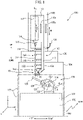
- FIG. 1 is a front view schematically showing primary constituent elements of an electric discharge-machine 100 to which the present invention is applied.
- the three orthogonal axial directions (X-axis direction, Y-axis direction, and Z-axis direction) are defined as the left-right directions, the front-rear directions, and the up-down directions, respectively, as shown in the drawings, and the configuration of each part will be described in accordance with these definitions.
- a column 104 stands on a rear part of an upper surface of a bed 102 serving as a base, and an X slider 106 is attached to an upper surface of the column 104 so as to be movable in the X-axis direction (left-right directions).
- a ram 108 is supported on an upper surface of the X slider 106 so as to be movable in the Y-axis direction (the front-rear directions; the direction orthogonal to the sheet of FIG. 1 ).
- a W-axis slider 110 is attached to a front surface of the ram 108 so as to be reciprocal in the W-axis direction parallel to the Z-axis (the up-down directions).
- a spindle head 112 is supported by the front surface of the W-axis slider 110 so as to be movable in the Z-axis direction.
- a spindle 114 is supported by the spindle head 112 so as to be rotatable about a central axis C L0 extending parallel to the Z-axis.
- An electrode holder 116 is mounted to the tip of the spindle 114 protruding from the bottom surface of the spindle head 112.
- a W-axis guide assembly 140 which will be described later, is attached to the W-axis slider 110.
- the W-axis guide assembly 140 comprises a guide arm 142 attached to the front surface of the W-axis slider 110.
- the guide arm 142 is a rod-shaped or box-shaped member which extends in the Z-axis direction and which moves in the up-down directions along with the W-axis slider 110.
- the movement axis of the W-axis slider 110 and the guide arm 142 is defined as the W-axis.
- the W-axis is parallel to the Z-axis.
- a power supply bar 154 composed of a conductive material is attached to one surface of the guide arm 142, and in the present embodiment, the side surface of the guide arm 142 facing the column 104, the X slider 106, and the ram 108.
- the power supply bar 154 is connected to a machining power supply device (not illustrated) via a cable 156.
- a power supply element assembly 10 is attached to the lower end of the guide arm 142.
- the machining power supply device is connected to a machine controller (not illustrated) of the electric discharge machine 100 and is controlled by the machine controller.
- the power supply element assembly 10 comprises a guide plate 12, a power supply base 20, a power supply brush assembly 30, and a power supply block 22 as primary constituent elements.
- the guide plate 12 is formed from a rectangular plate material, and an engagement hole 12a for engagement with a chuck 160 provided on the lower end 142a of the guide arm 142 is formed in the upper surface of the rear part (the right side in FIG. 5 ) of the guide plate 12. By engaging the chuck 160 with the engagement hole 12a, the guide plate 12 is attached to the lower end of the guide arm 142.
- the power supply base 20 which is composed of a conductive material, is attached to the upper surface of the guide plate 12 via an insulating plate 18.
- a first introduction plate 14 is attached to an upper surface of the power supply base 20 on the tip side.
- the first introduction plate 14 has an introduction hole 14a having a conical surface for guiding a pipe electrode 28 in the power supply base 20.
- the first introduction plate 14 is positioned and affixed to the power supply base 20 so that the apex of the conical surface of the introduction hole 14a is on the lower side and is arranged on the central axis C L0 of the spindle 114.
- An electrode guide 16 is attached to the lower part of the power supply assembly 10 as a positioning guide for inserting the lower end of the pipe electrode 28 movably in the axial direction and supporting the lower end of the pipe electrode 28.
- the electrode guide 16 projects downward from the lower surface of the guide plate 12, i.e., in the direction approaching a table 118, along the central axis C L0 of the spindle 114 at the tip portion on the side opposite the engagement hole 12a of the guide plate 12.
- the electrode guide 16 has an inner cavity 16a extending in the longitudinal direction, and is positioned with respect to the guide plate 12 so that the center of the inner cavity 16a is coaxial with the central axis C L0 .
- the inner cavity 16a has an inner diameter slightly larger than the outer diameter of the pipe electrode 28.
- a power supply brush assembly 30 is arranged on the lower side of the first introduction plate 14 directly above the electrode guide 16.
- the power supply brush assembly 30 comprises a pair of power supply brushes 32, 34.
- the power supply brushes 32, 34 have base parts 32a, 34a which are composed of a conductive material, and a large number of bristles 32b, 34b which are anchored in one side surface of the base parts 32a, 34a, respectively.
- the pair of power supply brushes 32, 34 are arranged symmetrically with respect to the central axis C L0 of the spindle 114, as shown in FIGS. 6 and 7 , so that in the power supply base 20, each of the bristles 32b, 34b extends in the transverse direction and the tip parts thereof face each other.
- the pair of power supply brushes 32, 34 are affixed to the power supply base 20 so as to be detachable and in electrical contact.
- the bristles 32b, 34b are formed from wire rods composed of a relatively flexible conductive material such as brass, and are preferably formed so as to be three-dimensionally wavy, as shown in FIG. 8 .
- a relatively flexible conductive material such as brass
- the bristles 32b, 34b are formed so as to be three-dimensionally wavy, gaps are secured between the bristles 32b, 34b, and as shown in FIG. 9 , it becomes easy to insert the pipe electrode 28 into the dense bristles 32b, 34b while ensuring contact with the pipe electrode 28.
- the pipe electrode 28 is inserted by pressing into the gaps between the bristles 32b, 34b. At this time, by rotating the pipe electrode 28 at high speed, flexibility of the pipe electrode 28 is suppressed. Further, by rotating the pipe electrode 28 at high speed, the friction between the bristles 32b, 34b and the pipe electrode 28 is reduced, whereby the pipe electrode 28 can be inserted into the dense bristles 32b, 34b without bending. By using bristles which are thinner than the pipe electrode, the bristles 32b, 34b can easily be deformed and gaps for inserting the pipe electrode 28 are secured. Further, the bristles 32b, 34b come into contact with the surface of the pipe electrode 28 due to the elastic force thereof. A plurality of bristles 32b, 34b contact the pipe electrode 28 simultaneously, whereby power can be stably supplied.
- the power supply brush assembly 30' has a pair of power supply brushes 32', 34', and the power supply brushes 32', 34' have base parts 32a', 34a' composed of a conductive material, and a large number of bristles 32b', 34b' which are anchored in one side surface of base parts 32a', 34a', respectively.
- the bristles 32b', 34b' may be formed from wire rods composed of a conductive material such as stainless steel, which is more rigid than brass.
- the bristles 32b, 34b of the power supply brushes 32, 34 have lengths such that the tips thereof are in contact or overlap in FIGS. 6 and 7 , in FIGS. 10 and 11 , the power supply brushes 32', 34' have comparatively short bristles 32b', 34b', and the tips of the bristles 32b', 34b' do not contact, whereby a gap G is formed therebetween.
- Appropriate thicknesses, lengths, and materials of the bristles 32b, 34b; 32b', 34b' are selected in accordance with the outer diameter of the pipe electrode 28.
- the gap G can be selected to be a positive value (a state in which the bristles 32b, 34b are spaced from each other), 0 (a state in which the tips of the bristles 32b, 34b contact or do not contact each other), or a negative value (a state in which the bristles 32b, 34b partially overlap each other).
- a second introduction plate 26 composed of an insulating material is arranged between the guide plate 12 and the power supply base 20.
- the second introduction plate 26 has an introduction hole 26a having a conical surface for guiding the pipe electrode 28 from the power supply base 20 into the electrode guide 16.
- the second introduction plate 26 is positioned and affixed to the power supply base 20 so that the apex of the conical surface of the introduction hole 26a faces the electrode guide 16 and is arranged on the central axis C L0 of the spindle 114.
- the power supply base 20 is electrically connected to the power supply bar 154 via a cable 162 and the power supply block 22.
- a bracket 158 protruding from the power supply bar 154 to the upper surface of the power supply base 20 is provided at the lower end of the power supply bar 154, and a coil spring 24 as a biasing means is arranged between the bracket 158 and the power supply block 22.
- the power supply block 22 is pressed against the upper surface of the power supply base 20 by the coil spring 24. It is preferable that an insulating plate 164 be arranged between the coil spring 24 and the bracket 158.
- the pipe electrode 28 extends along the axis C L0 between the electrode holder 116 and the electrode guide 16, and the upper end thereof is retained by the electrode holder 116. As the spindle 114 rotates about the axis C L0 , the pipe electrode 28 rotates about the axis C L0 together with the electrode holder 116.
- each of the electrode retention devices 144, 146, 148, 150, 152 has a pair of fingers 144a, 144b; 146a, 146b; 148a, 148b; 150a, 150b; 152a, 152b extending horizontally from the guide arm 142, and pads 144c, 144d; 146c, 146d; 148c, 148d; 150c, 150d; 152c, 152d attached to tips of the fingers 144a, 144b; 146a, 146b; 148a, 148b; 150a, 150b; 152a, 152b, respectively.
- Each pair of fingers 144a, 144b; 146a, 146b; 148a, 148b; 150a, 150b; 152a, 152b is pivotably attached to the guide arm 142 so as to be close to and spaced from each other in the horizontal direction centered on a common vertical axis.
- the electrode retention devices 144, 146, 148, 150, 152 are in closed positions in which the pads 144c, 144d; 146c, 146d; 148c, 148d; 150c, 150d; 152c, 152d contact each other, and in FIG.
- the material of the pads 144c, 144d; 146c, 146d; 148c, 148d; 150c, 150d; 152c, 152d is preferably a sponge having an appropriate frictional force when the pipe electrode 28 slides in the axial direction or rotates.
- a machining fluid such as, for example, water is supplied to the interior of the pipe electrode 28 via a machining fluid supply conduit (not illustrated) provided in the spindle 114 and a machining fluid supply conduit (not illustrated) formed in the electrode holder 116, and the machining fluid is sprayed from the tip (lower end) of the pipe electrode 28.
- oil may be used as the machining fluid.
- the electric-discharge machine 100 includes a machining fluid supply device (not illustrated) which supplies the machining fluid into the pipe electrode 28.
- the table 118 is arranged on the upper surface of the bed 102 in front of the column 104.
- An inclining rotating table device 120 is mounted on the upper surface of the table 118.
- the inclining rotating table device 120 comprises a pair of front and rear support members 122 projecting upward from the upper surface of the table 118, an inclining member 124 which is supported between the front and rear support members 122 so as to be capable of pivoting in the B-axis direction about a pivot axis C Lb extending in the Y-axis direction, and a rotating table 126 on the left end surface of the inclining member 124 which is rotatably supported in the A-axis direction about the rotation axis C La perpendicular to the pivot axis C Lb .
- a chuck 128 is provided on the rotating table 126, and a workpiece 130 is attached to the chuck 128.
- the workpiece 130 is, for example, a turbine blade or vane used in a gas turbine, and a cooling hole for flowing cooling air for cooling the surface of the turbine blade is formed in the surface of the turbine blade.
- a machining chamber 132 which can be raised and lowered so as to surround the entirety of the table 118 and the inclining rotating table device 120 is provided around the table 118.
- the alternate long and short dashed line in FIG. 1 represents a machining state in which the machining chamber 132 is raised, and in a non-machining state, such as during setup operations, the machining chamber 132 is lowered, as shown by the solid line.
- the electric-discharge machine 100 comprises a machining chamber drive device (not illustrated) which raises and lowers the machining chamber 132. When the machining chamber 132 is raised, the machining fluid is supplied from the machining fluid supply device to the machining chamber 132.
- the machining chamber drive device is connected to the machine controller of the electric-discharge machine 100, and the machine controller controls the supply of the machining fluid to the pipe electrode 28 and the machining chamber 132.
- the electric-discharge machine 100 of FIG. 1 comprises an X-axis drive unit which moves the X slider 106 in the left-right directions, a Y-axis drive unit which moves the ram 108 in the front-rear directions, a W-axis drive unit which moves the W-axis slider 110 in the up-down directions, a Z-axis drive unit which moves the spindle head 112 in the up-down directions, a spindle drive unit which rotates the spindle 114 about the axis C L0 , a B-axis drive unit which inclines the inclining member 124 via the pivot axis C Lb , and an A-axis drive unit which rotates the rotating table 126 via the rotation axis C La .
- the X-axis drive unit, Y-axis drive unit, Z-axis drive unit, and W-axis drive unit are each composed of, for example, a ball screw and a servomotor which rotationally-drives the ball screw
- the spindle drive unit is composed of, for example, a spindle motor
- the B-axis drive unit and A-axis drive unit each are composed of, for example, a DD (direct drive) servomotor.
- the X-axis drive unit, Y-axis drive unit, Z-axis drive unit, W-axis drive unit, spindle drive unit, B-axis drive unit, and A-axis drive unit are controlled by an NC device (not illustrated) of the electric-discharge machine 100.
- the electrode holder 116 and the electrode guide 16 can be moved relative to the workpiece 130 in the X-axis direction, Y-axis direction, and Z-axis direction, and can be moved relative to the workpiece 130 in the B-axis direction and the A-axis direction.
- a W-axis position detector 108a such as a linear scale for detecting the position of the W-axis slider 110 in the up-down directions is provided on the front surface of the ram 108.
- the W-axis position of the electrode guide 16 can be detected by the signal from the W-axis position detector 108a.
- a Z-axis position detector 110a such as a linear scale for detecting the position of the spindle head 112 in the up-down directions relative to the W-axis slider 110 is provided on the front surface of the W-axis slider 110.
- the position of the electrode holder 116 i.e., the position of the upper end portion of the pipe electrode 28, can be detected by the signal from the Z-axis position detector 110a and the signal from the W-axis position detector 108a.
- the W-axis position detector 108a and the Z-axis position detector 110a are connected to the NC device of the electric-discharge machine 100, and the Z-axis drive unit and the W-axis drive unit can be controlled based on the signals from the W-axis position detector 108a and the Z-axis position detector 110a.
- the electric-discharge machine 100 comprises finger drive units (not illustrated) which independently drive the fingers 144a, 144b; 146a, 146b; 148a, 148b; 150a, 150b; 152a, 152b of the electrode retention devices 144, 146, 148, 150, 152.
- the finger drive units are controlled by the machine controller of the electric-discharge machine 100 based on the position of the electrode holder 116 in the up-down directions.
- the distance between the electrode holder 116 and the electrode guide 16 can be adjusted, and regardless of changes in the length of the pipe electrode 28 due to wear of the pipe electrode 28, the upper and lower ends of the pipe electrode 28 can always be supported by the electrode holder 116 and the electrode guide 16 during machining.
- the topmost electrode retention device 144 moves to the open position, and next, the electrode retention device 146 therebelow moves to the open position, and in this manner, the electrode retention devices 144, 146, 148, 150, 152 move to the open position sequentially from the top.
- the electrode retention devices 144, 146, 148, 150, 152 move to the open position sequentially from the top.
- there is no interference between the electrode retention devices 144, 146, 148, 150, 152 which are in the open position, and the spindle head 112, and the electrode holder 116 can be lowered until it comes closest to the power supply element assembly 10.
- an electrode magazine can be provided on the side of the W-axis guide assembly 140.
- the electrode magazine holds a plurality of replacement pipe electrodes 28 mounted on a plurality of electrode holders 116, each having a predetermined initial length, and pipe electrodes 28 can be exchanged between the spindle 114 and the electrode magazine together with the electrode holders 116 by an exchange means (not illustrated).
- Pipe electrodes 28 having various outer diameters may be prepared in the electrode magazine.
- the electric-discharge machine 100 can comprise a guide magazine (not illustrated) for housing a plurality of electrode guides 16.
- the sizes of the electrode guides 16 are selected in accordance with the outer diameter of the pipe electrode 28 to be used, and various electrode guides 16 can be prepared and stored in advance in the guide magazine in a state in which a guide plate 12, an insulating plate 18, a power supply base 20, and a power supply brush assembly 30 in a form suitable for the outer diameter of the pipe electrode 28 to be used are integrated.
- a desired electrode guide 16 is attached to, detached from, and exchanged from the guide arm 142 at a portion of the chuck 160 by an unillustrated guide exchange device.
- the power supply brush assemblies 30, 30' are provided at a predetermined position directly above the electrode guide attached to the guide arm 142 in the present embodiment, as described above, regardless of the length of the pipe electrode 28, the distance L from the power supply position to the tip of the electrode guide 16 is always constant. Thus, the machining current between the pipe electrode 28 and the workpiece 130 becomes constant, the machining speed and the hole diameter to be machined do not change, and narrow holes can be stably machined.
Landscapes
- Engineering & Computer Science (AREA)
- Mechanical Engineering (AREA)
- Chemical & Material Sciences (AREA)
- Chemical Kinetics & Catalysis (AREA)
- Electrochemistry (AREA)
- Electrical Discharge Machining, Electrochemical Machining, And Combined Machining (AREA)
Abstract
Description
- The present invention relates to a narrow-hole electric discharge machine for electric-discharge machining of a narrow hole in a workpiece using a rod-shaped or pipe-shaped elongate electrode.
- In narrow-hole electric-discharge machining, a tip of a rod-shaped or pipe-shaped elongate narrow-hole electrode retained by a rotary spindle is guided toward a machining point of a workpiece surface by an electrode guide arranged near the workpiece, and a narrow hole is machined in the workpiece by relatively feeding the narrow-hole electrode in the Z-axis direction.
- Patent Literature 1 describes an electric-discharge machine which performs electric-discharge machining of a narrow hole in a workpiece by retaining one end of a narrow-hole electrode with a chuck provided on the tip of a machining head which is movable in the Z-axis direction, positioning the other end with an electrode guide part so as to face a workpiece in a machining chamber, and applying a pulse-shaped machining voltage from a power supply part between an electrode-side power supply member provided on an upper part of the chuck of the machining head and a workpiece-side electric conduction member attached to the workpiece while feeding the narrow-hole electrode in the Z-axis direction by the machining head.
- [PTL 1]
Japanese Unexamined Patent Publication (Kokai) No. 7-164249 - In the narrow-hole electric discharge machine of Patent Literature 1, since the machining voltage is applied to both ends of the narrow-hole electrode during electric-discharge machining, substantially the entire length of the narrow-hole electrode forms a part of an electric circuit for the application of the machining voltage. Thus, as the narrow-hole electrode is consumed and the length is reduced in accordance with the progress of machining, the resistance of the electric circuit to which the machining voltage is applied is reduced, whereby the machining current gradually increases. In particular, recently, since narrow-hole electrodes which are longer than in the prior art have been used to reduce the number of replacements of worn electrodes and improve machining efficiency, changes in machining current during machining also become large, whereby changes in machining speed and the diameter of the hole be machined also become large, which cannot be ignored.
- The present invention aims to solve such problems of the prior art, and to provide a narrow-hole electric discharge machine which can stably machine a narrow hole without changes in machining speed or the diameter of the hole to be machined even if the length of the narrow-hole electrode changes during electric-discharge machining.
- In order to achieve the object described above, according to the present invention, there is provided a narrow-hole electric discharge machine which performs electric-discharge machining on a workpiece by moving a narrow-hole electrode mounted on a spindle and a workpiece attached to a table relative to each other, the narrow-hole electric discharge machine comprising a positioning guide which is attached to a guide arm below the spindle and in which a lower part of the narrow-hole electrode is inserted and supported so that the narrow-hole electrode can move in an axial direction, and a power supply element which is provided in a predetermined position directly above the positioning guide of the guide arm and which directly contacts the narrow-hole electrode, which is movable in the axial direction, and supplies power thereto, wherein a distance from a power supply position to a tip of the positioning guide is constant regardless of the length of the narrow-hole electrode.
- According to the present invention, since the power supply element, which directly contacts and supplies power to the narrow-hole electrode, which is movable in the axial direction, is provided in a predetermined position directly above the positioning guide of the guide arm, the distance from the power supply position to the tip of the positioning guide is constant regardless of the length of the narrow-hole electrode, whereby the machining current between the narrow-hole electrode and the workpiece is constant, and a narrow hole can stably be machined without changes in machining speed or the diameter of the hole to be machined.
-
-
FIG. 1 is a front view of a narrow-hole electric discharge machine according to a preferred embodiment of the present invention. -
FIG. 2 is a perspective view showing a Z-axis slider, a spindle head, and a guide arm of the narrow-hole electric discharge machine ofFIG. 1 when an electrode retention device is closed. -
FIG. 3 is a perspective view showing a Z-axis slider, a spindle head, and a guide arm of the narrow-hole electric discharge machine ofFIG. 1 when an electrode retention device is open. -
FIG. 4 is a partially broken perspective view of a power supply element assembly. -
FIG. 5 is a side cross-sectional view of a power supply element assembly shown along with an electrode holder. -
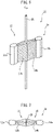
FIG. 6 is a perspective view of a power supply brush assembly shown along with a pipe electrode. -
FIG. 7 is a plan view of the power supply brush assembly ofFIG. 6 . -
FIG. 8 is a perspective view showing an example of a bristle used in the power supply brush. -
FIG. 9 is an enlarged schematic view of bristle tips of a power supply brush shown along with a pipe electrode. -
FIG. 10 is a perspective view identical toFIG. 6 , showing another example of a power supply brush assembly. -
FIG. 11 is a plan view of the power supply brush assembly ofFIG. 10 . - The preferred embodiments of the present invention will be described below with reference to the attached drawings.
-
FIG. 1 is a front view schematically showing primary constituent elements of an electric discharge-machine 100 to which the present invention is applied. Note that below, for convenience, the three orthogonal axial directions (X-axis direction, Y-axis direction, and Z-axis direction) are defined as the left-right directions, the front-rear directions, and the up-down directions, respectively, as shown in the drawings, and the configuration of each part will be described in accordance with these definitions. - In
FIG. 1 , acolumn 104 stands on a rear part of an upper surface of abed 102 serving as a base, and anX slider 106 is attached to an upper surface of thecolumn 104 so as to be movable in the X-axis direction (left-right directions). Aram 108 is supported on an upper surface of theX slider 106 so as to be movable in the Y-axis direction (the front-rear directions; the direction orthogonal to the sheet ofFIG. 1 ). A W-axis slider 110 is attached to a front surface of theram 108 so as to be reciprocal in the W-axis direction parallel to the Z-axis (the up-down directions). - A
spindle head 112 is supported by the front surface of the W-axis slider 110 so as to be movable in the Z-axis direction. Aspindle 114 is supported by thespindle head 112 so as to be rotatable about a central axis CL0 extending parallel to the Z-axis. Anelectrode holder 116 is mounted to the tip of thespindle 114 protruding from the bottom surface of thespindle head 112. A W-axis guide assembly 140, which will be described later, is attached to the W-axis slider 110. - The W-
axis guide assembly 140 comprises aguide arm 142 attached to the front surface of the W-axis slider 110. Theguide arm 142 is a rod-shaped or box-shaped member which extends in the Z-axis direction and which moves in the up-down directions along with the W-axis slider 110. The movement axis of the W-axis slider 110 and theguide arm 142 is defined as the W-axis. The W-axis is parallel to the Z-axis. - A
power supply bar 154 composed of a conductive material is attached to one surface of theguide arm 142, and in the present embodiment, the side surface of theguide arm 142 facing thecolumn 104, theX slider 106, and theram 108. Thepower supply bar 154 is connected to a machining power supply device (not illustrated) via acable 156. A powersupply element assembly 10 is attached to the lower end of theguide arm 142. The machining power supply device is connected to a machine controller (not illustrated) of theelectric discharge machine 100 and is controlled by the machine controller. - Referring to
FIGS. 4 and5 , the powersupply element assembly 10 comprises aguide plate 12, apower supply base 20, a powersupply brush assembly 30, and apower supply block 22 as primary constituent elements. - The
guide plate 12 is formed from a rectangular plate material, and anengagement hole 12a for engagement with achuck 160 provided on thelower end 142a of theguide arm 142 is formed in the upper surface of the rear part (the right side inFIG. 5 ) of theguide plate 12. By engaging thechuck 160 with theengagement hole 12a, theguide plate 12 is attached to the lower end of theguide arm 142. - The
power supply base 20, which is composed of a conductive material, is attached to the upper surface of theguide plate 12 via aninsulating plate 18. Afirst introduction plate 14 is attached to an upper surface of thepower supply base 20 on the tip side. Thefirst introduction plate 14 has anintroduction hole 14a having a conical surface for guiding apipe electrode 28 in thepower supply base 20. Thefirst introduction plate 14 is positioned and affixed to thepower supply base 20 so that the apex of the conical surface of theintroduction hole 14a is on the lower side and is arranged on the central axis CL0 of thespindle 114. - An
electrode guide 16 is attached to the lower part of thepower supply assembly 10 as a positioning guide for inserting the lower end of thepipe electrode 28 movably in the axial direction and supporting the lower end of thepipe electrode 28. Theelectrode guide 16 projects downward from the lower surface of theguide plate 12, i.e., in the direction approaching a table 118, along the central axis CL0 of thespindle 114 at the tip portion on the side opposite theengagement hole 12a of theguide plate 12. Theelectrode guide 16 has aninner cavity 16a extending in the longitudinal direction, and is positioned with respect to theguide plate 12 so that the center of theinner cavity 16a is coaxial with the central axis CL0. Theinner cavity 16a has an inner diameter slightly larger than the outer diameter of thepipe electrode 28. - In the
power supply base 20, a powersupply brush assembly 30 is arranged on the lower side of thefirst introduction plate 14 directly above theelectrode guide 16. The powersupply brush assembly 30 comprises a pair ofpower supply brushes power supply brushes base parts bristles base parts - The pair of
power supply brushes spindle 114, as shown inFIGS. 6 and 7 , so that in thepower supply base 20, each of thebristles power supply brushes power supply base 20 so as to be detachable and in electrical contact. - The
bristles FIG. 8 . By forming thebristles bristles FIG. 9 , it becomes easy to insert thepipe electrode 28 into thedense bristles pipe electrode 28. - The
pipe electrode 28 is inserted by pressing into the gaps between thebristles pipe electrode 28 at high speed, flexibility of thepipe electrode 28 is suppressed. Further, by rotating thepipe electrode 28 at high speed, the friction between thebristles pipe electrode 28 is reduced, whereby thepipe electrode 28 can be inserted into thedense bristles bristles pipe electrode 28 are secured. Further, thebristles pipe electrode 28 due to the elastic force thereof. A plurality ofbristles pipe electrode 28 simultaneously, whereby power can be stably supplied. - When a
thick pipe electrode 28 is used, a short-bristled power supply brush assembly can be used. InFIGS. 10 and 11 , in the same manner as the powersupply brush assembly 30 shown inFIGS. 6 and 7 , the power supply brush assembly 30' has a pair of power supply brushes 32', 34', and the power supply brushes 32', 34' havebase parts 32a', 34a' composed of a conductive material, and a large number ofbristles 32b', 34b' which are anchored in one side surface ofbase parts 32a', 34a', respectively. Thebristles 32b', 34b' may be formed from wire rods composed of a conductive material such as stainless steel, which is more rigid than brass. - Though the
bristles FIGS. 6 and 7 , inFIGS. 10 and 11 , the power supply brushes 32', 34' have comparativelyshort bristles 32b', 34b', and the tips of thebristles 32b', 34b' do not contact, whereby a gap G is formed therebetween. - Appropriate thicknesses, lengths, and materials of the
bristles pipe electrode 28. The gap G can be selected to be a positive value (a state in which thebristles bristles bristles pipe electrode 28 can be inserted into the powersupply brush assemblies 30, 30' without bending and power can be stably supplied. - A
second introduction plate 26 composed of an insulating material is arranged between theguide plate 12 and thepower supply base 20. Thesecond introduction plate 26 has anintroduction hole 26a having a conical surface for guiding thepipe electrode 28 from thepower supply base 20 into theelectrode guide 16. Thesecond introduction plate 26 is positioned and affixed to thepower supply base 20 so that the apex of the conical surface of theintroduction hole 26a faces theelectrode guide 16 and is arranged on the central axis CL0 of thespindle 114. - The
power supply base 20 is electrically connected to thepower supply bar 154 via acable 162 and thepower supply block 22. Abracket 158 protruding from thepower supply bar 154 to the upper surface of thepower supply base 20 is provided at the lower end of thepower supply bar 154, and acoil spring 24 as a biasing means is arranged between thebracket 158 and thepower supply block 22. Thepower supply block 22 is pressed against the upper surface of thepower supply base 20 by thecoil spring 24. It is preferable that an insulatingplate 164 be arranged between thecoil spring 24 and thebracket 158. - The
pipe electrode 28 extends along the axis CL0 between theelectrode holder 116 and theelectrode guide 16, and the upper end thereof is retained by theelectrode holder 116. As thespindle 114 rotates about the axis CL0, thepipe electrode 28 rotates about the axis CL0 together with theelectrode holder 116. - In the
guide arm 142, at least one, and in the illustrated embodiment, fiveelectrode retention devices pipe electrode 28. Each of theelectrode retention devices fingers 144a, 144b; 146a, 146b; 148a, 148b; 150a, 150b; 152a, 152b extending horizontally from theguide arm 142, andpads fingers 144a, 144b; 146a, 146b; 148a, 148b; 150a, 150b; 152a, 152b, respectively. - Each pair of
fingers 144a, 144b; 146a, 146b; 148a, 148b; 150a, 150b; 152a, 152b is pivotably attached to theguide arm 142 so as to be close to and spaced from each other in the horizontal direction centered on a common vertical axis. InFIG. 2 , theelectrode retention devices pads FIG. 3 , are in open positions in which thepads electrode retention devices pipe electrode 28 is slidably retained between thepads pads pipe electrode 28 slides in the axial direction or rotates. - A machining fluid such as, for example, water is supplied to the interior of the
pipe electrode 28 via a machining fluid supply conduit (not illustrated) provided in thespindle 114 and a machining fluid supply conduit (not illustrated) formed in theelectrode holder 116, and the machining fluid is sprayed from the tip (lower end) of thepipe electrode 28. Note that oil may be used as the machining fluid. The electric-discharge machine 100 includes a machining fluid supply device (not illustrated) which supplies the machining fluid into thepipe electrode 28. - The table 118 is arranged on the upper surface of the
bed 102 in front of thecolumn 104. An inclining rotatingtable device 120 is mounted on the upper surface of the table 118. The incliningrotating table device 120 comprises a pair of front andrear support members 122 projecting upward from the upper surface of the table 118, an incliningmember 124 which is supported between the front andrear support members 122 so as to be capable of pivoting in the B-axis direction about a pivot axis CLb extending in the Y-axis direction, and a rotating table 126 on the left end surface of the incliningmember 124 which is rotatably supported in the A-axis direction about the rotation axis CLa perpendicular to the pivot axis CLb. Achuck 128 is provided on the rotating table 126, and aworkpiece 130 is attached to thechuck 128. Theworkpiece 130 is, for example, a turbine blade or vane used in a gas turbine, and a cooling hole for flowing cooling air for cooling the surface of the turbine blade is formed in the surface of the turbine blade. - A
machining chamber 132 which can be raised and lowered so as to surround the entirety of the table 118 and the inclining rotatingtable device 120 is provided around the table 118. The alternate long and short dashed line inFIG. 1 represents a machining state in which themachining chamber 132 is raised, and in a non-machining state, such as during setup operations, themachining chamber 132 is lowered, as shown by the solid line. The electric-discharge machine 100 comprises a machining chamber drive device (not illustrated) which raises and lowers themachining chamber 132. When themachining chamber 132 is raised, the machining fluid is supplied from the machining fluid supply device to themachining chamber 132. The machining chamber drive device is connected to the machine controller of the electric-discharge machine 100, and the machine controller controls the supply of the machining fluid to thepipe electrode 28 and themachining chamber 132. - Though illustration thereof has been omitted, the electric-
discharge machine 100 ofFIG. 1 comprises an X-axis drive unit which moves theX slider 106 in the left-right directions, a Y-axis drive unit which moves theram 108 in the front-rear directions, a W-axis drive unit which moves the W-axis slider 110 in the up-down directions, a Z-axis drive unit which moves thespindle head 112 in the up-down directions, a spindle drive unit which rotates thespindle 114 about the axis CL0, a B-axis drive unit which inclines the incliningmember 124 via the pivot axis CLb, and an A-axis drive unit which rotates the rotating table 126 via the rotation axis CLa. - The X-axis drive unit, Y-axis drive unit, Z-axis drive unit, and W-axis drive unit are each composed of, for example, a ball screw and a servomotor which rotationally-drives the ball screw, the spindle drive unit is composed of, for example, a spindle motor, and the B-axis drive unit and A-axis drive unit each are composed of, for example, a DD (direct drive) servomotor. The X-axis drive unit, Y-axis drive unit, Z-axis drive unit, W-axis drive unit, spindle drive unit, B-axis drive unit, and A-axis drive unit are controlled by an NC device (not illustrated) of the electric-
discharge machine 100. As a result, theelectrode holder 116 and theelectrode guide 16 can be moved relative to theworkpiece 130 in the X-axis direction, Y-axis direction, and Z-axis direction, and can be moved relative to theworkpiece 130 in the B-axis direction and the A-axis direction. - A W-
axis position detector 108a such as a linear scale for detecting the position of the W-axis slider 110 in the up-down directions is provided on the front surface of theram 108. The W-axis position of theelectrode guide 16 can be detected by the signal from the W-axis position detector 108a. A Z-axis position detector 110a such as a linear scale for detecting the position of thespindle head 112 in the up-down directions relative to the W-axis slider 110 is provided on the front surface of the W-axis slider 110. The position of theelectrode holder 116, i.e., the position of the upper end portion of thepipe electrode 28, can be detected by the signal from the Z-axis position detector 110a and the signal from the W-axis position detector 108a. The W-axis position detector 108a and the Z-axis position detector 110a are connected to the NC device of the electric-discharge machine 100, and the Z-axis drive unit and the W-axis drive unit can be controlled based on the signals from the W-axis position detector 108a and the Z-axis position detector 110a. - The electric-
discharge machine 100 comprises finger drive units (not illustrated) which independently drive thefingers 144a, 144b; 146a, 146b; 148a, 148b; 150a, 150b; 152a, 152b of theelectrode retention devices discharge machine 100 based on the position of theelectrode holder 116 in the up-down directions. - In the present embodiment, by raising and lowering the
spindle head 112 with respect to the W-axis slider 110, the distance between theelectrode holder 116 and theelectrode guide 16 can be adjusted, and regardless of changes in the length of thepipe electrode 28 due to wear of thepipe electrode 28, the upper and lower ends of thepipe electrode 28 can always be supported by theelectrode holder 116 and theelectrode guide 16 during machining. At that time, to prevent interference between theelectrode holder 116 and theelectrode retention devices spindle head 112 moves down along the Z axis, first, the topmostelectrode retention device 144 moves to the open position, and next, theelectrode retention device 146 therebelow moves to the open position, and in this manner, theelectrode retention devices electrode retention devices spindle head 112, and theelectrode holder 116 can be lowered until it comes closest to the powersupply element assembly 10. - Though illustration thereof has been omitted, an electrode magazine can be provided on the side of the W-
axis guide assembly 140. The electrode magazine holds a plurality ofreplacement pipe electrodes 28 mounted on a plurality ofelectrode holders 116, each having a predetermined initial length, andpipe electrodes 28 can be exchanged between thespindle 114 and the electrode magazine together with theelectrode holders 116 by an exchange means (not illustrated).Pipe electrodes 28 having various outer diameters may be prepared in the electrode magazine. - The electric-
discharge machine 100 can comprise a guide magazine (not illustrated) for housing a plurality of electrode guides 16. The sizes of the electrode guides 16 are selected in accordance with the outer diameter of thepipe electrode 28 to be used, and various electrode guides 16 can be prepared and stored in advance in the guide magazine in a state in which aguide plate 12, an insulatingplate 18, apower supply base 20, and a powersupply brush assembly 30 in a form suitable for the outer diameter of thepipe electrode 28 to be used are integrated. A desiredelectrode guide 16 is attached to, detached from, and exchanged from theguide arm 142 at a portion of thechuck 160 by an unillustrated guide exchange device. - Since the power
supply brush assemblies 30, 30' are provided at a predetermined position directly above the electrode guide attached to theguide arm 142 in the present embodiment, as described above, regardless of the length of thepipe electrode 28, the distance L from the power supply position to the tip of theelectrode guide 16 is always constant. Thus, the machining current between thepipe electrode 28 and theworkpiece 130 becomes constant, the machining speed and the hole diameter to be machined do not change, and narrow holes can be stably machined. -
- 10
- power supply element assembly
- 12
- guide plate
- 16
- electrode guide
- 20
- power supply base
- 22
- power supply block
- 28
- pipe electrode
- 30
- power supply brush assembly
- 32
- power supply brush
- 34
- power supply brush
- 100
- electric-discharge machine
- 112
- spindle head
- 114
- spindle
- 116
- electrode holder
- 118
- table
- 142
- guide arm
- 144
- electrode retention device
Claims (7)
- A narrow-hole electric discharge machine which performs electric-discharge machining on a workpiece by moving a narrow-hole electrode mounted on a spindle and a workpiece attached to a table relative to each other, the narrow-hole electric discharge machine comprising:a positioning guide which is attached to a guide arm below the spindle and in which a lower part of the narrow-hole electrode is inserted and supported so that the narrow-hole electrode can move in an axial direction, anda power supply element which is provided in a predetermined position directly above the positioning guide of the guide arm and which directly contacts the narrow-hole electrode, which is movable in the axial direction, and supplies power thereto, whereina distance from a power supply position to a tip of the positioning guide is constant regardless of the length of the narrow-hole electrode.
- The narrow-hole electric discharge machine according to claim 1, wherein the power supply element comprises a power supply brush having a large number of bristles composed of a conductive material extending in a transverse direction relative to the axial direction of the narrow-hole electrode, and the narrow-hole electrode is inserted into the power supply element so as to contact the bristles and pass through the power supply brush.
- The narrow-hole electric discharge machine according to claim 2, wherein the power supply element further comprises a first introduction plate which is arranged above the power supply brush and which has a narrow-hole electrode introduction hole having a conical surface, and the first introduction plate is arranged on a movement path of the narrow-hole electrode with an apex of the conical surface facing toward the power supply brush.
- The narrow-hole electric discharge machine according to claim 2, wherein the power supply further comprises a second introduction plate arranged below the power supply brush and having a narrow-hole electrode introduction hole having a conical surface, and the second introduction plate is arranged on a movement path of the narrow-hole electrode with an apex of the conical surface facing toward the positioning guide.
- The narrow-hole electric discharge machine according to claim 1, further comprising at least one electrode retention device which is arranged between the spindle and the power supply element and which retains a side surface of the narrow-hole electrode.
- The narrow-hole electric discharge machine according to claim 5, wherein the electrode retention device comprises a pair of pads provided so as to be capable of contacting the side surface of the narrow-hole electrode and a pair of arms which capable of being driven so as to bring the pair of pads closer to each other and separate them from each other.
- The narrow-hole electric discharge machine according to claim 6, wherein the pair of arms are driven to move the pads away from the movement path of the narrow-hole electrode in accordance with the position of the spindle so that the electrode retention device does not interfere with the spindle during electric-discharge machining.
Applications Claiming Priority (2)
| Application Number | Priority Date | Filing Date | Title |
|---|---|---|---|
| JP2019107312A JP6807984B2 (en) | 2019-06-07 | 2019-06-07 | Small hole electric discharge machine |
| PCT/JP2020/021790 WO2020246469A1 (en) | 2019-06-07 | 2020-06-02 | Narrow-hole electric discharge machine |
Publications (2)
| Publication Number | Publication Date |
|---|---|
| EP3981534A1 true EP3981534A1 (en) | 2022-04-13 |
| EP3981534A4 EP3981534A4 (en) | 2023-08-23 |
Family
ID=73653225
Family Applications (1)
| Application Number | Title | Priority Date | Filing Date |
|---|---|---|---|
| EP20819373.0A Pending EP3981534A4 (en) | 2019-06-07 | 2020-06-02 | Narrow-hole electric discharge machine |
Country Status (5)
| Country | Link |
|---|---|
| US (1) | US12128492B2 (en) |
| EP (1) | EP3981534A4 (en) |
| JP (1) | JP6807984B2 (en) |
| CN (1) | CN113874148B (en) |
| WO (1) | WO2020246469A1 (en) |
Families Citing this family (1)
| Publication number | Priority date | Publication date | Assignee | Title |
|---|---|---|---|---|
| CN118848136B (en) * | 2024-09-20 | 2025-01-14 | 国营川西机器厂 | Self-adaptive positioning method for turbine blade tip electric spark forming |
Family Cites Families (10)
| Publication number | Priority date | Publication date | Assignee | Title |
|---|---|---|---|---|
| JPS60249531A (en) * | 1984-05-21 | 1985-12-10 | Mitsubishi Electric Corp | Electricity feeding apparatus in wire-cut electric discharge machine |
| JP2565680B2 (en) * | 1986-05-27 | 1996-12-18 | 株式会社ソディック | Perforation electric discharge machining attachment |
| JP3241780B2 (en) | 1991-12-17 | 2001-12-25 | 株式会社ソディック | Pore electric discharge machine |
| JPH06143043A (en) * | 1992-11-04 | 1994-05-24 | Murata Mfg Co Ltd | Minute hole electric discharge machining method and device |
| JP3335741B2 (en) | 1993-12-15 | 2002-10-21 | 株式会社ソディック | Small hole electric discharge machine |
| JP3963679B2 (en) * | 2001-09-05 | 2007-08-22 | 株式会社牧野フライス製作所 | Electric discharge machine |
| US10493548B2 (en) * | 2015-03-31 | 2019-12-03 | Makino Milling Machine Co., Ltd. | Fine hole electrical discharge machine |
| WO2016189617A1 (en) * | 2015-05-25 | 2016-12-01 | 三菱電機株式会社 | Support device and electrical discharge machine |
| CN106392217A (en) * | 2016-12-13 | 2017-02-15 | 安徽理工大学 | Micro hole machining method and equipment |
| JP6861864B1 (en) | 2020-01-28 | 2021-04-21 | 株式会社牧野フライス製作所 | Small hole electric discharge machine |
-
2019
- 2019-06-07 JP JP2019107312A patent/JP6807984B2/en active Active
-
2020
- 2020-06-02 WO PCT/JP2020/021790 patent/WO2020246469A1/en not_active Ceased
- 2020-06-02 US US17/616,838 patent/US12128492B2/en active Active
- 2020-06-02 EP EP20819373.0A patent/EP3981534A4/en active Pending
- 2020-06-02 CN CN202080039152.6A patent/CN113874148B/en active Active
Also Published As
| Publication number | Publication date |
|---|---|
| JP6807984B2 (en) | 2021-01-06 |
| CN113874148B (en) | 2024-09-10 |
| JP2020199574A (en) | 2020-12-17 |
| CN113874148A (en) | 2021-12-31 |
| WO2020246469A1 (en) | 2020-12-10 |
| EP3981534A4 (en) | 2023-08-23 |
| US20220347776A1 (en) | 2022-11-03 |
| US12128492B2 (en) | 2024-10-29 |
Similar Documents
| Publication | Publication Date | Title |
|---|---|---|
| CN101589518A (en) | Adjustable power contactor | |
| US12128492B2 (en) | Narrow-hole electric discharge machine | |
| CN217452479U (en) | Numerical control wire-electrode cutting processing equipment | |
| CN220330174U (en) | Automatic threading detection positioning mechanism | |
| EP0083118B1 (en) | Helicoidal guide for wire electrode of an edm apparatus | |
| JP3963679B2 (en) | Electric discharge machine | |
| JPWO2001089752A1 (en) | Electric discharge machining equipment for small hole machining | |
| US20090236318A1 (en) | Wire Electric Discharge Machining Apparatus | |
| JP2671663B2 (en) | Wire electric discharge machine | |
| WO2001089752A1 (en) | Electric dischage machine for making thin hole | |
| CN215034365U (en) | Argon arc welding equipment | |
| KR20100039670A (en) | Electrode replacement apparatus of supper drilling electric discharge machining | |
| JPH11170119A (en) | Holding device for electric discharge machining electrode | |
| JP3161687B2 (en) | EDM equipped with automatic electrode guide changing device | |
| EP0463066A4 (en) | Electrical discharge machine apparatus tilted current pickup | |
| JPS6034219A (en) | Electric discharge machine | |
| JP4147722B2 (en) | EDM machine | |
| JP3575993B2 (en) | Electric discharge machine | |
| EP1393844A2 (en) | Wire electric discharge machine | |
| JP4817364B2 (en) | Contact detection device for machine tools | |
| KR101843289B1 (en) | Method and apparatus for checking electrode bar away from guide of electrical discharge machine | |
| CN119658043B (en) | Electric spark machine tool for machining die | |
| CN104801757A (en) | Machine head of automatic pipe cutting machine | |
| CN223222650U (en) | Semi-automatic micro spot welding machine | |
| JPS58501274A (en) | Reverse automatic stop device in electrical discharge machine |
Legal Events
| Date | Code | Title | Description |
|---|---|---|---|
| STAA | Information on the status of an ep patent application or granted ep patent |
Free format text: STATUS: THE INTERNATIONAL PUBLICATION HAS BEEN MADE |
|
| PUAI | Public reference made under article 153(3) epc to a published international application that has entered the european phase |
Free format text: ORIGINAL CODE: 0009012 |
|
| STAA | Information on the status of an ep patent application or granted ep patent |
Free format text: STATUS: REQUEST FOR EXAMINATION WAS MADE |
|
| 17P | Request for examination filed |
Effective date: 20211203 |
|
| AK | Designated contracting states |
Kind code of ref document: A1 Designated state(s): AL AT BE BG CH CY CZ DE DK EE ES FI FR GB GR HR HU IE IS IT LI LT LU LV MC MK MT NL NO PL PT RO RS SE SI SK SM TR |
|
| DAV | Request for validation of the european patent (deleted) | ||
| DAX | Request for extension of the european patent (deleted) | ||
| RIN1 | Information on inventor provided before grant (corrected) |
Inventor name: SUGAWARA, SUSUMU |
|
| A4 | Supplementary search report drawn up and despatched |
Effective date: 20230720 |
|
| RIC1 | Information provided on ipc code assigned before grant |
Ipc: B23H 7/26 20060101ALI20230714BHEP Ipc: B23H 11/00 20060101ALI20230714BHEP Ipc: B23H 9/14 20060101ALI20230714BHEP Ipc: B23H 7/14 20060101ALI20230714BHEP Ipc: B23H 1/00 20060101AFI20230714BHEP |