EP3981366B1 - Prosthetic foot - Google Patents
Prosthetic foot Download PDFInfo
- Publication number
- EP3981366B1 EP3981366B1 EP21164406.7A EP21164406A EP3981366B1 EP 3981366 B1 EP3981366 B1 EP 3981366B1 EP 21164406 A EP21164406 A EP 21164406A EP 3981366 B1 EP3981366 B1 EP 3981366B1
- Authority
- EP
- European Patent Office
- Prior art keywords
- forefoot
- curved plate
- carbon fiber
- arc
- curve
- Prior art date
- Legal status (The legal status is an assumption and is not a legal conclusion. Google has not performed a legal analysis and makes no representation as to the accuracy of the status listed.)
- Active
Links
Images


Classifications
-
- A—HUMAN NECESSITIES
- A61—MEDICAL OR VETERINARY SCIENCE; HYGIENE
- A61F—FILTERS IMPLANTABLE INTO BLOOD VESSELS; PROSTHESES; DEVICES PROVIDING PATENCY TO, OR PREVENTING COLLAPSING OF, TUBULAR STRUCTURES OF THE BODY, e.g. STENTS; ORTHOPAEDIC, NURSING OR CONTRACEPTIVE DEVICES; FOMENTATION; TREATMENT OR PROTECTION OF EYES OR EARS; BANDAGES, DRESSINGS OR ABSORBENT PADS; FIRST-AID KITS
- A61F2/00—Filters implantable into blood vessels; Prostheses, i.e. artificial substitutes or replacements for parts of the body; Appliances for connecting them with the body; Devices providing patency to, or preventing collapsing of, tubular structures of the body, e.g. stents
- A61F2/50—Prostheses not implantable in the body
- A61F2/60—Artificial legs or feet or parts thereof
- A61F2/66—Feet; Ankle joints
-
- A—HUMAN NECESSITIES
- A61—MEDICAL OR VETERINARY SCIENCE; HYGIENE
- A61F—FILTERS IMPLANTABLE INTO BLOOD VESSELS; PROSTHESES; DEVICES PROVIDING PATENCY TO, OR PREVENTING COLLAPSING OF, TUBULAR STRUCTURES OF THE BODY, e.g. STENTS; ORTHOPAEDIC, NURSING OR CONTRACEPTIVE DEVICES; FOMENTATION; TREATMENT OR PROTECTION OF EYES OR EARS; BANDAGES, DRESSINGS OR ABSORBENT PADS; FIRST-AID KITS
- A61F2/00—Filters implantable into blood vessels; Prostheses, i.e. artificial substitutes or replacements for parts of the body; Appliances for connecting them with the body; Devices providing patency to, or preventing collapsing of, tubular structures of the body, e.g. stents
- A61F2/50—Prostheses not implantable in the body
- A61F2/60—Artificial legs or feet or parts thereof
- A61F2/66—Feet; Ankle joints
- A61F2002/6614—Feet
- A61F2002/665—Soles
-
- A—HUMAN NECESSITIES
- A61—MEDICAL OR VETERINARY SCIENCE; HYGIENE
- A61F—FILTERS IMPLANTABLE INTO BLOOD VESSELS; PROSTHESES; DEVICES PROVIDING PATENCY TO, OR PREVENTING COLLAPSING OF, TUBULAR STRUCTURES OF THE BODY, e.g. STENTS; ORTHOPAEDIC, NURSING OR CONTRACEPTIVE DEVICES; FOMENTATION; TREATMENT OR PROTECTION OF EYES OR EARS; BANDAGES, DRESSINGS OR ABSORBENT PADS; FIRST-AID KITS
- A61F2/00—Filters implantable into blood vessels; Prostheses, i.e. artificial substitutes or replacements for parts of the body; Appliances for connecting them with the body; Devices providing patency to, or preventing collapsing of, tubular structures of the body, e.g. stents
- A61F2/50—Prostheses not implantable in the body
- A61F2/60—Artificial legs or feet or parts thereof
- A61F2/66—Feet; Ankle joints
- A61F2002/6614—Feet
- A61F2002/6657—Feet having a plate-like or strip-like spring element, e.g. an energy-storing cantilever spring keel
- A61F2002/6664—Dual structures made of two connected cantilevered leaf springs
Definitions
- the present invention relates to a prosthetic foot as set out in the claims.
- a carbon fiber prosthetic foot is basically straight in a transverse direction and made by taking longitudinal arch features of a human foot as a reference, carbon fibers are mainly distributed in a length direction of a prosthetic foot, which ensures a strength of the prosthetic foot in the length direction, but makes a strength of the prosthetic foot weak in a transverse direction, and a market generally use thickened carbon fiber plates to solve a strength problem, which increases a weight and cost of the prosthetic foot and reduces a use effect and a comfort level of a prosthesis.
- the document US 2015/0289996 A1 discloses an adjustable length prosthetic foot, a foot prosthesis that includes at least one spring element, an attachment member, and a heel member.
- the at least one spring element has a toe end portion, a heel end portion, an upper surface, and a lower surface.
- the attachment member is mounted to the upper surface and is configured to connect the foot prosthesis to a lower limb prosthesis component.
- a position of the attachment member is adjustable along a length of the at least one spring element.
- the heel member is mounted below the lower surface of the at least one spring element, and a position of the heel member is adjustable along the length of the at least one spring element.
- the present invention provides a prosthetic foot as set out in the claims.
- Three-dimensional curvature features of a longitudinal arch and a transverse arch of a human foot are combined into a design of a prosthetic carbon fiber foot, which changes a conventional design of the carbon fiber foot straight in a transverse direction, on one hand, weight of the prosthetic foot is reduced while overall rigidity of the prosthetic foot is improved, and on the other hand, the rigidity distribution of the foot is changed in a gradient manner due to different curvatures of different transverse positions of the prosthetic foot, which dynamically meets different requirements of different road conditions and different walking stages on the rigidity of different parts of the prosthetic foot.
- Some embodiments of the present invention include a forefoot carbon fiber curved plate A, a heel carbon fiber curved plate B, a connection assembly C, a first bolt set 1, a second bolt set 2 and a third bolt set 3, wherein a square cone joint 6 of the connection assembly C, an upper connection base 7 of the connection assembly C, a rear part of the forefoot carbon fiber curved plate A, an upper part of the heel carbon fiber curved plate B and a lower abutting plate 8 of the connection assembly C are sequentially arranged from top to bottom; a square table 6b of the square cone joint 6 in the connection assembly C is arranged in a square shallow recessed groove 7d of the upper connection base 7 and is fixedly connected by the first bolt set 1, a center of the square cone joint 6 is provided with a stepped hole 6a, the first bolt set 1 is penetrated in the stepped hole 6a; a third left hole 7c of a first arc side wing 7b of the upper connection base 7 in the connection assembly C, a first left hole 4a of
- the forefoot carbon fiber curved plate A includes a rear arc portion 4c, a middle curved surface portion 4d, a left foretoe 4e, a right foretoe 4f, and the forefoot longitudinal curve G, wherein the first left hole 4a and the first right hole 4b are provided in a rear part of the rear arc portion 4c; a shape of a transverse curved surface of the forefoot carbon fiber curved plate A is determined by a first cross-sectional curve D in a rear of the forefoot carbon fiber curved plate A, a second cross-sectional curve E in a middle of the forefoot carbon fiber curved plate A and a third cross-sectional curve F in a front of the curved plate, wherein
- Shapes of the second cross-sectional curve E and the third cross-sectional curve F are drawn according to a basic shape of the transverse arch of the human body, and have a larger curvature of inner sides and a smaller curvature of outer sides;
- the rear arc portion 4c is an arc cylindrical surface which is controlled by the first cross-sectional curve D and has a thickness of 4-5 mm, and the first left hole 4a and the first right hole 4b are provided in a rear part of the rear arc portion 4c;
- the middle curved surface portion 4d is a curved surface formed by the first cross-sectional curve D and the second cross-sectional curve E;
- an entire front part of the forefoot carbon fiber curved plate A is a curved surface formed by the second cross-sectional curve E and the third cross-sectional curve F, and a bottommost part thereof is an upward straight arc surface and is divided into the left foretoe 4e and the right foretoe 4f by a thin groove 41 in a middle of
- the heel carbon fiber curved plate B includes an upper arc portion 5c, a middle transition portion 5d, a lower curved plate portion 5e and a heel longitudinal curve H, wherein the upper arc portion 5a is an arc plate with transversely distributed curvature and has a shape matched with a first cross-sectional curve D in the forefoot carbon fiber curved plate A; two symmetrical through holes, that is, the second left hole 5a and the second right hole 5b, are provided in a left side and a right side of the upper arc portion 5c; a bottommost part of the lower curved plate portion 5e is an upward transverse straight arc surface; the upper arc portion 5c and the lower curved plate potion 5e are smoothly connected together by the middle transition portion 5d; a thickness of a curved plate of the upper arc portion 5c of the heel carbon fiber curved plate B is uniform and is 5-7 mm; and a thickness of the middle transition portion 5d and a thickness of the lower curved plate part 5e are uniformly changed
- the heel longitudinal curve H includes a first heel longitudinal curve section 5f and a second heel longitudinal curve section 5g, wherein the first heel longitudinal curve section 5f includes an inclined straight line and an arc, wherein the arc has a radius r 3 of 70-80 mm and a central angle ⁇ 3 of 130°-150°, and the first heel longitudinal curve section is located on an upper middle part of the heel longitudinal curve H, wherein the second heel longitudinal curve section 5g includes an inclined straight line and an arc, having an arc radius r 4 of 60-70 mm and a central angle ⁇ 4 of 8°-12°, and is located on a lower part of the heel longitudinal curve H, and the first heel longitudinal curve section 5f and the second heel longitudinal curve section 5g are in smooth tangent connection by the straight line.
- the connection assembly C includes the square cone joint 6, the upper connection base 7 and the lower abutting plate 8, wherein a lower part of the square cone joint 6 is the square table 6b;
- the upper connection base 7 includes a middle platform 7a, and the first arc side wing 7b and the second arc side wing 7f which are symmetrically arranged left and right, wherein the middle platform 7a is a hollow triangular pyramid frustum horizontally disposed in a left-right direction, the square shallow recessed groove 7d and a middle hole 7e are provided in a top face of the middle platform 7a, the third left hole 7c is provided in the first arc side wing 7b, and the third right hole 7g is provided in the second arc side wing 7f; the fourth left hole 8a and the fourth right hole 8b are provided in the lower abutting plate 8; and the square cone joint 6, the upper connection base 7 and the lower abutting plate 8 are sequentially arranged from top to bottom.
- a prosthetic foot including a forefoot carbon fiber curved plate, a heel carbon fiber curved plate, a connection assembly C, a first fastening assembly, a second fastening assembly, and a third fastening assembly; a square cone joint of the connection assembly is disposed in a square shallow recessed groove of an upper connection base and is connected by the first fastening assembly, a center of the square cone joint is provided with a stepped hole, the first fastening assembly is penetrated in the stepped hole; a first arc side wing of the upper connection base in the connection assembly, the forefoot carbon fiber curved plate, the heel carbon fiber curved plate and a lower abutting plate in the connection assembly are fixedly connected by the third fastening assembly; a second arc side wing of the upper connection base in the connection assembly, the forefoot carbon fiber curved plate, the heel carbon fiber curved plate and the lower abutting plate in the connection assembly are fixedly connected by the second fastening assembly; and the
- the first fastening assembly is a first bolt set
- the second fastening assembly is a second bolt set
- the third fastening assembly is a third bolt set.
- the square cone joint of the connection assembly, the upper connection base of the connection assembly, the rear part of the forefoot carbon fiber curved plate, the upper part of the heel carbon fiber curved plate and the lower abutting plate of the connection assembly are sequentially arranged from top to bottom.
- the forefoot carbon fiber curved plate has a forefoot longitudinal curve
- the heel carbon fiber curved plate has a heel longitudinal curve
- the forefoot longitudinal curve and the heel longitudinal curve form the longitudinal arch shape
- the forefoot longitudinal curve includes a first forefoot longitudinal curve section and a second forefoot longitudinal curve section, wherein the first forefoot longitudinal curve section is a straight line section with an inclination angle of 23°-30° relative to a horizontal plane, the second forefoot longitudinal curve section is an arc, and has a arc radius r 2 of 70-80 mm and a central angle ⁇ 2 of 50°-60°, the second forefoot longitudinal curve section is located at a tail end of a front part of the forefoot longitudinal curve, and the first forefoot longitudinal curve section and the second forefoot longitudinal curve section are in smooth tangent connection.
- the transverse arch shape of the forefoot carbon fiber curved plate includes a first cross-sectional curve in the rear of the curved plate, a second cross-sectional curve in the middle of the curved plate, and a third cross-sectional curve in the front of the curved plate; and the forefoot carbon fiber curved plate includes a rear arc portion, a middle curved surface portion, a first front portion and a second front portion which are sequentially connected, wherein the first cross-sectional curve is arranged on a connection surface between the rear arc portion and the middle curved surface portion, the second cross-sectional curve is disposed on a connection surface between the middle curved surface portion and the first front portion, the third cross-sectional curve is disposed on a connection surface between the first front portion and the second front potion, and a left foretoe and a right foretoe are arranged on the first front potion and the second front potion.
- third bolt set 4a. first left hole 4b. first right hole 4c. rear arc portion 4d. middle curved surface portion 4e. left foretoe 4f. right foretoe 5a. second left hole 5b. second right hole 5c. upper arc portion 5d. middle transition portion 5e. lower curved plate portion 4g. first forefoot longitudinal curve section 4h. second forefoot longitudinal curve section 5f. first heel longitudinal curve section 5g. second heel longitudinal curve section 6.
- the present invention includes a forefoot carbon fiber curved plate A, a heel carbon fiber curved plate B, a connection assembly C, a first bolt set 1, a second bolt set 2 and a third bolt set 3, wherein a square cone joint 6 of the connection assembly C, an upper connection base 7 of the connection assembly C, a rear part of the forefoot carbon fiber curved plate A, an upper part of the heel carbon fiber curved plate B and a lower abutting plate 8 of the connection assembly C are sequentially arranged from top to bottom; a square table 6b of the square cone joint 6 in the connection assembly C is arranged in a square shallow recessed groove 7d of the upper connection base 7 and is fixedly connected by the first bolt set 1; a third left hole 7c of a first arc side wing 7b of the upper connection base 7 in the connection assembly C, a first left hole 4a of the forefoot carbon fiber curved plate A, a second left hole 5a of the heel carbon fiber curved plate B
- the forefoot carbon fiber curved plate A includes a rear arc portion 4c, a middle curved surface portion 4d, a left foretoe 4e, a right foretoe 4f, and the forefoot longitudinal curve G, wherein the first left hole 4a and the first right hole 4b are provided in a rear part of the rear arc portion 4c; a shape of a transverse curved surface of the forefoot carbon fiber curved plate A is determined by a first cross-sectional curve D in a rear of the forefoot carbon fiber curved plate A, a second cross-sectional curve E in a middle of the forefoot carbon fiber curved plate and a third cross-sectional curve F in the front of the forefoot carbon fiber curved plate, wherein the first cross-sectional curve D is an arc curve, and has an arc radius r 1 of 30-35 mm and a central angle ⁇ 1 of 50°-60°;
- Shapes of the second cross-sectional curve E and the third cross-sectional curve F are drawn according to a basic shape of the transverse arch of the human body, and have a larger curvature of inner sides and a smaller curvature of outer sides;
- the rear arc portion 4c is an arc cylindrical surface which is controlled by the first cross-sectional curve D and has a thickness of 4-5 mm, and the first left hole 4a and the first right hole 4b are provided in a rear part of the rear arc portion 4c;
- the middle curved surface portion 4d is a curved surface formed by the first cross-sectional curve D and the second cross-sectional curve E;
- an entire front part of the forefoot carbon fiber curved plate A is a curved surface formed by the second cross-sectional curve E and the third cross-sectional curve F, and a bottommost part thereof is an upward straight arc surface and is divided into the left foretoe 4e and the right foretoe 4f by a thin groove 4g in the middle of the
- the heel carbon fiber curved plate B includes an upper arc portion 5c, a middle transition portion 5d, a lower curved plate portion 5e and a heel longitudinal curve H, wherein the upper arc portion 5a is an arc plate with transversely distributed curvature and has a shape matched with a first cross-sectional curve D in the forefoot carbon fiber curved plate A; two symmetrical through holes, that is, the second left hole 5a and the second right hole 5b, are provided in a left side and a right side of the upper arc portion 5c; a bottommost part of the lower curved plate portion 5e is an upward transverse straight arc surface; the upper arc portion 5c and the lower curved plate potion 5e are smoothly connected together by the middle transition portion 5d; a thickness of a curved plate of the upper arc portion 5c of the heel carbon fiber curved plate B is uniform and is 5-7 mm; and a thickness of the middle transition portion 5d and a thickness of the
- the heel longitudinal curve H includes a first heel longitudinal curve section 5f and a second heel longitudinal curve section 5g, wherein the first heel longitudinal curve section 5f includes an inclined straight line and an arc, wherein the arc has a radiusr 3 of 70-80 mm and a central angle ⁇ 3 of 130°-150°, and the first heel longitudinal curve section is located on an upper middle part of the heel longitudinal curve H, wherein the second heel longitudinal curve section 5g includes an inclined straight line and an arc, having an arc radius r 4 of 60-70 mm and a central angle ⁇ 4 of 8°-12°, and is located on a lower part of the heel longitudinal curve H, and the first heel longitudinal curve section 5f and the second heel longitudinal curve section 5g are in smooth tangent connection by the straight line.
- the connection assembly C includes the square cone joint 6, the upper connection base 7 and the lower abutting plate 8, wherein a lower part of the square cone joint 6 is the square table 6b, and a center of the square cone joint 6 is provided with a stepped hole 6a;
- the upper connection base 7 includes a middle platform 7a, and the first arc side wing 7b and the second arc side wing 7f which are symmetrically arranged left and right, wherein the middle platform 7a is a hollow triangular pyramid frustum horizontally disposed in a left-right direction, the square shallow recessed groove 7d and a middle hole 7e are provided in a top face of the middle platform 7a, the third left hole 7c is provided in the first arc side wing 7b, and the third right hole 7g is provided in the second arc side wing 7f; the fourth left hole 8a and the fourth right hole 8b are provided in the lower abutting plate 8; and the square cone joint 6, the upper connection base 7 and
- the present invention provides a prosthetic foot, including a forefoot carbon fiber curved plate A, a heel carbon fiber curved plate B, a connection assembly (C), a first fastening assembly, a second fastening assembly, and a third fastening assembly; a square cone joint 6 of the connection assembly C is disposed in a square shallow recessed groove 7d of an upper connection base 7 and is connected by the first fastening assembly; a first arc side wing 7b of the upper connection base 7 in the connection assembly C, the forefoot carbon fiber curved plate A, the heel carbon fiber curved plate B and a lower abutting plate 8 in the connection assembly C are fixedly connected by the third fastening assembly; a second arc side wing 7f of the upper connection base 7 in the connection assembly C, the forefoot carbon fiber curved plate A, the heel carbon fiber curved plate B and the lower abutting plate 8 in the connection assembly C are fixedly connected by the second fastening assembly; and the forefoot carbon fiber curved plate A and the
- the longitudinal arch shape refers to an arch-shaped structure which protrudes upwards in a length direction (that is, a front-back direction) of the human foot or the prosthetic foot and has a certain radian
- the transverse arch refers to an arch-shaped structure which protrudes upwards in a width direction (that is, an inner-outer direction) of the human foot or the prosthetic foot and has a certain radian.
- the first fastening assembly is a first bolt set 1
- the second fastening assembly is a second bolt set 2
- the third fastening assembly is a third bolt set 3.
- connection assembly C the square cone joint 6 of the connection assembly C, the upper connection base 7 of the connection assembly C, a rear part of the forefoot carbon fiber curved plate A, an upper part of the heel carbon fiber curved plate B and the lower abutting plate 8 of the connection assembly C are sequentially arranged from top to bottom.
- the forefoot carbon fiber curved plate A has a forefoot longitudinal curve G
- the heel carbon fiber curved plate B has a heel longitudinal curve H
- the forefoot longitudinal curve g and the heel longitudinal curve H form the longitudinal arch shape
- the forefoot longitudinal curve G includes a first forefoot longitudinal curve section 4g and a second forefoot longitudinal curve section 4h, wherein the first forefoot longitudinal curve section 4g is a straight line section with an inclination angle of 23°-30° relative to a horizontal plane
- the second forefoot longitudinal curve section 4h is an arc, and has a arc radius r 2 of 70-80 mm and a central angle ⁇ 2 of 50°-60°
- the second forefoot longitudinal curve section 4h is located at a tail end of a front part of the forefoot longitudinal curve G
- the first forefoot longitudinal curve section 4g and the second forefoot longitudinal curve section 4h are in smooth tangent connection.
- the transverse arch shape of the forefoot carbon fiber curved plate A includes a first cross-sectional curve D in the rear of the curved plate, a second cross-sectional curve E in the middle of the curved plate, and a third cross-sectional curve F in the front of the curved plate; and the forefoot carbon fiber curved plate A includes a rear arc portion 4c, a middle curved surface portion 4d, a first front portion and a second front portion which are sequentially connected, wherein the first cross-sectional curve D is arranged on a connection surface between the rear arc portion 4c and the middle curved surface portion 4d, the second cross-sectional curve E is disposed on a connection surface between the middle curved surface portion 4d and the first front portion, the third cross-sectional curve F is disposed on a connection surface between the first front portion and the second front potion, and a left foretoe 4e and a right foretoe 4f are disposed on the first front potion and the second front potion.
- the first cross-sectional curve D is an arc curve, and has an arc radius r 1 of 30-35 mm and a central angle ⁇ 1 of 50°-60°;
Landscapes
- Health & Medical Sciences (AREA)
- Transplantation (AREA)
- Vascular Medicine (AREA)
- Life Sciences & Earth Sciences (AREA)
- Oral & Maxillofacial Surgery (AREA)
- Engineering & Computer Science (AREA)
- Biomedical Technology (AREA)
- Heart & Thoracic Surgery (AREA)
- Orthopedic Medicine & Surgery (AREA)
- Cardiology (AREA)
- Animal Behavior & Ethology (AREA)
- General Health & Medical Sciences (AREA)
- Public Health (AREA)
- Veterinary Medicine (AREA)
- Prostheses (AREA)
- Footwear And Its Accessory, Manufacturing Method And Apparatuses (AREA)
Description
- The present invention relates to a prosthetic foot as set out in the claims.
- With a rapid increase of modern social problems of disease, aging, traffic accidents, etc., a number of amputees have been increasing. Installation of a prosthesis is an effective engineering method to make up for a function loss caused by a missing limb, so worldwide attention has been paid to a research and development of prosthetic equipment and life support equipment for disabled people.
- In recent years, carbon fiber-reinforced composite materials have been widely used in a field of prostheses because of their advantages of being lighter and more attractive. At present, a carbon fiber prosthetic foot is basically straight in a transverse direction and made by taking longitudinal arch features of a human foot as a reference, carbon fibers are mainly distributed in a length direction of a prosthetic foot, which ensures a strength of the prosthetic foot in the length direction, but makes a strength of the prosthetic foot weak in a transverse direction, and a market generally use thickened carbon fiber plates to solve a strength problem, which increases a weight and cost of the prosthetic foot and reduces a use effect and a comfort level of a prosthesis.
- Researches show that a transverse arch of a human foot plays an important role in ensuring the overall stiffness of the human foot, which is a key factor in ensuring normal walking of a human body. Therefore, it is necessary to provide a novel prosthetic foot combining the longitudinal arch and transverse arch features of a human foot; on the one hand, the novel prosthetic foot can play a good role in weight bearing and supporting and propelling, so as to ensure rational strength and rational rigidity distribution of a bearing part of the prosthetic foot; and on the other hand, the prosthetic foot is light as much as possible, so as to improve a using effect and comfort level of a prosthesis.
- The document
US 2015/0289996 A1 discloses an adjustable length prosthetic foot, a foot prosthesis that includes at least one spring element, an attachment member, and a heel member. The at least one spring element has a toe end portion, a heel end portion, an upper surface, and a lower surface. The attachment member is mounted to the upper surface and is configured to connect the foot prosthesis to a lower limb prosthesis component. A position of the attachment member is adjustable along a length of the at least one spring element. The heel member is mounted below the lower surface of the at least one spring element, and a position of the heel member is adjustable along the length of the at least one spring element. - As for defects of an existing prosthetic foot, the present invention provides a prosthetic foot as set out in the claims. Three-dimensional curvature features of a longitudinal arch and a transverse arch of a human foot are combined into a design of a prosthetic carbon fiber foot, which changes a conventional design of the carbon fiber foot straight in a transverse direction, on one hand, weight of the prosthetic foot is reduced while overall rigidity of the prosthetic foot is improved, and on the other hand, the rigidity distribution of the foot is changed in a gradient manner due to different curvatures of different transverse positions of the prosthetic foot, which dynamically meets different requirements of different road conditions and different walking stages on the rigidity of different parts of the prosthetic foot.
- Some embodiments of the present invention include a forefoot carbon fiber curved plate A, a heel carbon fiber curved plate B, a connection assembly C, a
first bolt set 1, asecond bolt set 2 and athird bolt set 3, wherein asquare cone joint 6 of the connection assembly C, anupper connection base 7 of the connection assembly C, a rear part of the forefoot carbon fiber curved plate A, an upper part of the heel carbon fiber curved plate B and alower abutting plate 8 of the connection assembly C are sequentially arranged from top to bottom; a square table 6b of thesquare cone joint 6 in the connection assembly C is arranged in a square shallowrecessed groove 7d of theupper connection base 7 and is fixedly connected by thefirst bolt set 1, a center of thesquare cone joint 6 is provided with astepped hole 6a, thefirst bolt set 1 is penetrated in thestepped hole 6a; a thirdleft hole 7c of a firstarc side wing 7b of theupper connection base 7 in the connection assembly C, a firstleft hole 4a of the forefoot carbon fiber curved plate A, a secondleft hole 5a of the heel carbon fiber curved plate B and a fourthleft hole 8a of thelower abutting plate 8 in the connection assembly C are fixedly connected by thethird bolt set 3; a thirdright hole 7g of a secondarc side wing 7f of theupper connection base 7 in the connection assembly C, a firstright hole 4b of the forefoot carbon fiber curved plate A, a secondright hole 5b of the heel carbon fiber curved plate B and a fourthright hole 8b of thelower abutting plate 8 in the connection assembly C are fixedly connected by thesecond bolt set 2; and
a forefoot longitudinal curve G of the forefoot carbon fiber curved plate A and a heel longitudinal curve H of the heel carbon fiber curved plate B integrally form a longitudinal arch shape. - The forefoot carbon fiber curved plate A includes a
rear arc portion 4c, a middlecurved surface portion 4d, aleft foretoe 4e, aright foretoe 4f, and the forefoot longitudinal curve G, wherein the firstleft hole 4a and the firstright hole 4b are provided in a rear part of therear arc portion 4c; a shape of a transverse curved surface of the forefoot carbon fiber curved plate A is determined by a first cross-sectional curve D in a rear of the forefoot carbon fiber curved plate A, a second cross-sectional curve E in a middle of the forefoot carbon fiber curved plate A and a third cross-sectional curve F in a front of the curved plate, wherein - the first cross-sectional curve D is an arc curve, and has an arc radius r1 of 30-35 mm and a central angle θ1 of 50°-60°;
- a mathematical expression of the second cross-sectional curve E is:

- a mathematical expression of the third cross-sectional curve F is:

- Shapes of the second cross-sectional curve E and the third cross-sectional curve F are drawn according to a basic shape of the transverse arch of the human body, and have a larger curvature of inner sides and a smaller curvature of outer sides; the
rear arc portion 4c is an arc cylindrical surface which is controlled by the first cross-sectional curve D and has a thickness of 4-5 mm, and the firstleft hole 4a and the firstright hole 4b are provided in a rear part of therear arc portion 4c; the middlecurved surface portion 4d is a curved surface formed by the first cross-sectional curve D and the second cross-sectional curve E; an entire front part of the forefoot carbon fiber curved plate A is a curved surface formed by the second cross-sectional curve E and the third cross-sectional curve F, and a bottommost part thereof is an upward straight arc surface and is divided into theleft foretoe 4e and the right foretoe 4f by a thin groove 41 in a middle of a front part of the forefoot carbon fiber curved plate A; a thickness from the middlecurved surface portion 4d to top ends of theleft foretoe 4e and theright foretoe 4f is uniformly changed, from large to small, from back to front, a maximum thickness is identical to a thickness of therear arc portion 4c, and a minimum thickness is 2.5 mm; and the forefoot longitudinal curve G includes a first forefootlongitudinal curve section 4g and a second forefootlongitudinal curve section 4h, the first forefootlongitudinal curve section 4g is a straight line section with an inclination angle of 23°-30°, and the second forefootlongitudinal curve section 4h is an arc, having an arc radius r2 of 70-80 mm and a central angle θ2 of 50°-60°, and being located at a tail end of the front part of the forefoot longitudinal curve G, and the first forefootlongitudinal curve section 4g and the second forefootlongitudinal curve section 4h are in smooth tangent connection. - The heel carbon fiber curved plate B includes an
upper arc portion 5c, amiddle transition portion 5d, a lowercurved plate portion 5e and a heel longitudinal curve H, wherein theupper arc portion 5a is an arc plate with transversely distributed curvature and has a shape matched with a first cross-sectional curve D in the forefoot carbon fiber curved plate A; two symmetrical through holes, that is, the secondleft hole 5a and the secondright hole 5b, are provided in a left side and a right side of theupper arc portion 5c; a bottommost part of the lowercurved plate portion 5e is an upward transverse straight arc surface; theupper arc portion 5c and the lowercurved plate potion 5e are smoothly connected together by themiddle transition portion 5d; a thickness of a curved plate of theupper arc portion 5c of the heel carbon fiber curved plate B is uniform and is 5-7 mm; and a thickness of themiddle transition portion 5d and a thickness of the lowercurved plate part 5e are uniformly changed, from large to small, from back to front, a maximum thickness of each of themiddle transition portion 5d and the lowercurved plate part 5e is consistent with a thickness of theupper arc portion 5c, and a minimum thickness is 3 mm. - The heel longitudinal curve H includes a first heel
longitudinal curve section 5f and a second heellongitudinal curve section 5g, wherein the first heellongitudinal curve section 5f includes an inclined straight line and an arc, wherein the arc has a radius r3 of 70-80 mm and a central angle θ3 of 130°-150°, and the first heel longitudinal curve section is located on an upper middle part of the heel longitudinal curve H, wherein the second heellongitudinal curve section 5g includes an inclined straight line and an arc, having an arc radius r4 of 60-70 mm and a central angle θ4 of 8°-12°, and is located on a lower part of the heel longitudinal curve H, and the first heellongitudinal curve section 5f and the second heellongitudinal curve section 5g are in smooth tangent connection by the straight line. - The connection assembly C includes the
square cone joint 6, theupper connection base 7 and thelower abutting plate 8, wherein a lower part of thesquare cone joint 6 is the square table 6b; theupper connection base 7 includes amiddle platform 7a, and the firstarc side wing 7b and the secondarc side wing 7f which are symmetrically arranged left and right, wherein themiddle platform 7a is a hollow triangular pyramid frustum horizontally disposed in a left-right direction, the square shallowrecessed groove 7d and amiddle hole 7e are provided in a top face of themiddle platform 7a, the thirdleft hole 7c is provided in the firstarc side wing 7b, and the thirdright hole 7g is provided in the secondarc side wing 7f; the fourthleft hole 8a and the fourthright hole 8b are provided in thelower abutting plate 8; and thesquare cone joint 6, theupper connection base 7 and the lowerabutting plate 8 are sequentially arranged from top to bottom. - Some embodiments of the present invention provide a prosthetic foot, including a forefoot carbon fiber curved plate, a heel carbon fiber curved plate, a connection assembly C, a first fastening assembly, a second fastening assembly, and a third fastening assembly; a square cone joint of the connection assembly is disposed in a square shallow recessed groove of an upper connection base and is connected by the first fastening assembly, a center of the square cone joint is provided with a stepped hole, the first fastening assembly is penetrated in the stepped hole; a first arc side wing of the upper connection base in the connection assembly, the forefoot carbon fiber curved plate, the heel carbon fiber curved plate and a lower abutting plate in the connection assembly are fixedly connected by the third fastening assembly; a second arc side wing of the upper connection base in the connection assembly, the forefoot carbon fiber curved plate, the heel carbon fiber curved plate and the lower abutting plate in the connection assembly are fixedly connected by the second fastening assembly; and the forefoot carbon fiber curved plate and the heel carbon fiber curved plate form a longitudinal arch shape, and the forefoot carbon fiber curved plate forms a transverse arch shape.
- In some embodiments, the first fastening assembly is a first bolt set, the second fastening assembly is a second bolt set, and the third fastening assembly is a third bolt set.
- In some embodiments, the square cone joint of the connection assembly, the upper connection base of the connection assembly, the rear part of the forefoot carbon fiber curved plate, the upper part of the heel carbon fiber curved plate and the lower abutting plate of the connection assembly are sequentially arranged from top to bottom.
- In some embodiments, the forefoot carbon fiber curved plate has a forefoot longitudinal curve, and the heel carbon fiber curved plate has a heel longitudinal curve, and the forefoot longitudinal curve and the heel longitudinal curve form the longitudinal arch shape, and the forefoot longitudinal curve includes a first forefoot longitudinal curve section and a second forefoot longitudinal curve section, wherein the first forefoot longitudinal curve section is a straight line section with an inclination angle of 23°-30° relative to a horizontal plane, the second forefoot longitudinal curve section is an arc, and has a arc radius r2 of 70-80 mm and a central angle θ2 of 50°-60°, the second forefoot longitudinal curve section is located at a tail end of a front part of the forefoot longitudinal curve, and the first forefoot longitudinal curve section and the second forefoot longitudinal curve section are in smooth tangent connection.
- In some embodiments, the transverse arch shape of the forefoot carbon fiber curved plate includes a first cross-sectional curve in the rear of the curved plate, a second cross-sectional curve in the middle of the curved plate, and a third cross-sectional curve in the front of the curved plate; and the forefoot carbon fiber curved plate includes a rear arc portion, a middle curved surface portion, a first front portion and a second front portion which are sequentially connected, wherein the first cross-sectional curve is arranged on a connection surface between the rear arc portion and the middle curved surface portion, the second cross-sectional curve is disposed on a connection surface between the middle curved surface portion and the first front portion, the third cross-sectional curve is disposed on a connection surface between the first front portion and the second front potion, and a left foretoe and a right foretoe are arranged on the first front potion and the second front potion.
- In some embodiments, the first cross-sectional curve is an arc curve, and has an arc radius r1 of 30-35 mm and a central angle θ1 of 50°-60°; a mathematical expression of the second cross-sectional curve is:y = -0.00009x3 + 0.015x2 + 0.02x + 31.5 ; and a mathematical expression of the third cross-sectional curve is:

- The present invention has the beneficial effects:
- 1. The conventional carbon fiber prosthetic foot straight in the transverse direction is changed, the shape of the transverse curved surface of the prosthetic foot is designed in combination with the three-dimensional curvature features of the longitudinal arch and the transverse arch of the human foot, and a transversely bent carbon fiber plate improves the overall rigidity of the prosthetic foot while reducing the thickness of the carbon fiber plate, so as to achieve better supporting and propelling effects and lighter and more comfortable use experience; and
- 2. according to the three-dimensional curvature change features of the longitudinal arch and the transverse arch of the human foot, a transverse curvature of the carbon fiber prosthetic foot is designed into gradient change, such that the rigidity distribution of the prosthetic foot is changed in a gradient manner, which better meet the human engineering. Generally, the rigidity distribution of the prosthetic foot is as follows: the rigidity of the rear part is larger, and the rigidity of the front part is smaller; and the rigidity of inner partial toes is larger, and the rigidity of outer partial toes is smaller. The present invention is simple in design structure, but can dynamically meet different requirements on the rigidity of a bearing part and a part, for transmitting ground reaction force, of the prosthetic foot under different road conditions and different movement states, such that the response of the prosthetic foot to the movement is more intelligent, timely and reliable.
- The accompanying drawings, forming a part of the present application, of the description serve to provide a further understanding of the present invention, and the illustrative embodiments of the present invention and the description of the illustrative embodiments serve to explain the present invention and are not to be construed as unduly limiting the present invention. In the drawings:
-
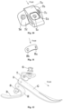
Fig. 1 illustrates an axonometric view (in a rear right direction) of a prosthetic foot with a gradient rigidity change and curvature features of a transverse arch of a human body. -
Fig. 2 illustrates an axonometric view (in a front right direction) of the prosthetic foot with the gradient rigidity change and the curvature features of the transverse arch of the human body. -
Fig. 3 illustrates an axonometric view (in a front right direction) of a forefoot carbon fiber curved plate A. -
Fig. 4 illustrates a structural schematic diagram (a front view) of the forefoot carbon fiber curved plate A. -
Fig. 5 illustrates a cross-sectional view (in a front right direction) of the forefoot carbon fiber curved plate A. -
Fig. 6 illustrates an axonometric view (in a rear right direction) of a heel carbon fiber curved plate B. -
Fig. 7 illustrates a structural schematic diagram (a right view) of a forefoot longitudinal curve G and a heel longitudinal curve H. -
Fig. 8 illustrates an axonometric view of a connection assembly C. -
Fig. 9 illustrates an axonometric view of asquare cone joint 6. -
Fig. 10 illustrates an axonometric view of anupper connection base 7. -
Fig. 11 illustrates an axonometric view of a lowerabutting plate 8. -
Fig. 12 illustrates an axonometric view of an arrangement relation among the forefoot carbon fiber curved plate A, the heel carbon fiber curved plate B, and the connection assembly C. - In the figures: A. forefoot carbon fiber curved plate B. heel carbon fiber curved plate C. connection assembly D. first cross-sectional curve E. second cross-sectional curve F. third cross-sectional curve G. forefoot longitudinal curve H. heel
longitudinal curve 1. first bolt set 2. second bolt set 3. third bolt set 4a. firstleft hole 4b. firstright hole 4c.rear arc portion 4d. middlecurved surface portion 4e. left foretoe 4f. right foretoe 5a. secondleft hole 5b. secondright hole 5c.upper arc portion 5d.middle transition portion 5e. lowercurved plate portion 4g. first forefootlongitudinal curve section 4h. second forefootlongitudinal curve section 5f. first heellongitudinal curve section 5g. second heellongitudinal curve section 6. square cone joint 6a. steppedhole 6b. square table 7.upper connection base 7a.middle platform 7b. firstarc side wing 7c. thirdleft hole 7d. square shallow recessedgroove 7e.middle hole 7f. secondarc side wing 7g. thirdright hole 8. lower abuttingplate 8a. fourthleft hole 8b. fourth right hole - It should be noted that the embodiments of the present application and the features of the embodiments may be combined with one another without conflict. The present invention will be described in detail below with reference to the accompanying drawings and in conjunction with the embodiments.
- The present invention will be described hereafter in conjunction with the accompanying drawings.
- As shown in
Figs. 1, 2 and12 , the present invention includes a forefoot carbon fiber curved plate A, a heel carbon fiber curved plate B, a connection assembly C, a first bolt set 1, a second bolt set 2 and a third bolt set 3, wherein a square cone joint 6 of the connection assembly C, an upper connection base 7 of the connection assembly C, a rear part of the forefoot carbon fiber curved plate A, an upper part of the heel carbon fiber curved plate B and a lower abutting plate 8 of the connection assembly C are sequentially arranged from top to bottom; a square table 6b of the square cone joint 6 in the connection assembly C is arranged in a square shallow recessed groove 7d of the upper connection base 7 and is fixedly connected by the first bolt set 1; a third left hole 7c of a first arc side wing 7b of the upper connection base 7 in the connection assembly C, a first left hole 4a of the forefoot carbon fiber curved plate A, a second left hole 5a of the heel carbon fiber curved plate B and a fourth left hole 8a of the lower abutting plate 8 in the connection assembly C are fixedly connected by the third bolt set 3; a third right hole 7g of a second arc side wing 7f of the upper connection base 7 in the connection assembly C, a first right hole 4b of the forefoot carbon fiber curved plate A, a second right hole 5b of the heel carbon fiber curved plate B and a fourth right hole 8b of the lower abutting plate 8 in the connection assembly C are fixedly connected by the second bolt set 2; and
a forefoot longitudinal curve G of the forefoot carbon fiber curved plate A and a heel longitudinal curve H of the heel carbon fiber curved plate B integrally form a longitudinal arch shape. - As shown in
Figs. 3-5 and7 , the forefoot carbon fiber curved plate A includes arear arc portion 4c, a middlecurved surface portion 4d, a left foretoe 4e, a right foretoe 4f, and the forefoot longitudinal curve G, wherein the firstleft hole 4a and the firstright hole 4b are provided in a rear part of therear arc portion 4c; a shape of a transverse curved surface of the forefoot carbon fiber curved plate A is determined by a first cross-sectional curve D in a rear of the forefoot carbon fiber curved plate A, a second cross-sectional curve E in a middle of the forefoot carbon fiber curved plate and a third cross-sectional curve F in the front of the forefoot carbon fiber curved plate, wherein the first cross-sectional curve D is an arc curve, and has an arc radius r1 of 30-35 mm and a central angle θ1 of 50°-60°; - a mathematical expression of the second cross-sectional curve E is:

- and a mathematical expression of the third cross-sectional curve F is:

- Shapes of the second cross-sectional curve E and the third cross-sectional curve F are drawn according to a basic shape of the transverse arch of the human body, and have a larger curvature of inner sides and a smaller curvature of outer sides; the
rear arc portion 4c is an arc cylindrical surface which is controlled by the first cross-sectional curve D and has a thickness of 4-5 mm, and the firstleft hole 4a and the firstright hole 4b are provided in a rear part of therear arc portion 4c; the middlecurved surface portion 4d is a curved surface formed by the first cross-sectional curve D and the second cross-sectional curve E;
an entire front part of the forefoot carbon fiber curved plate A is a curved surface formed by the second cross-sectional curve E and the third cross-sectional curve F, and a bottommost part thereof is an upward straight arc surface and is divided into the left foretoe 4e and the right foretoe 4f by a thin groove 4g in the middle of the front part of the forefoot carbon fiber curved plate A; a thickness from the middle curved surface portion 4d to the top ends of the left foretoe 4e and the right foretoe 4f is uniformly changed, from large to small, from back to front, a maximum thickness is identical to a thickness of the rear arc portion 4c, and a minimum thickness is 2.5 mm; and the forefoot longitudinal curve G includes a first forefoot longitudinal curve section 4g and a second forefoot longitudinal curve section 4h, the first forefoot longitudinal curve section 4g is a straight line section with an inclination angle of 23°-30°, and the second forefoot longitudinal curve section 4h is an arc, having an arc radius r2 of 70-80 mm and a central angle θ2 of 50°-60°, and is located at a tail end of the front part of the forefoot longitudinal curve G, and the first forefoot longitudinal curve section 4g and the second forefoot longitudinal curve section 4h are in smooth tangent connection. - As shown in
Figs. 6 and7 , the heel carbon fiber curved plate B includes an upper arc portion 5c, a middle transition portion 5d, a lower curved plate portion 5e and a heel longitudinal curve H, wherein the upper arc portion 5a is an arc plate with transversely distributed curvature and has a shape matched with a first cross-sectional curve D in the forefoot carbon fiber curved plate A; two symmetrical through holes, that is, the second left hole 5a and the second right hole 5b, are provided in a left side and a right side of the upper arc portion 5c; a bottommost part of the lower curved plate portion 5e is an upward transverse straight arc surface; the upper arc portion 5c and the lower curved plate potion 5e are smoothly connected together by the middle transition portion 5d; a thickness of a curved plate of the upper arc portion 5c of the heel carbon fiber curved plate B is uniform and is 5-7 mm; and a thickness of the middle transition portion 5d and a thickness of the lower curved plate part 5e are uniformly changed, from large to small, from back to front, a maximum thickness of each of the middle transition portion 5d and the lower curved plate part 5e is consistent with a thickness of the upper arc portion 5c, and a minimum thickness is 3 mm. - The heel longitudinal curve H includes a first heel
longitudinal curve section 5f and a second heellongitudinal curve section 5g, wherein the first heellongitudinal curve section 5f includes an inclined straight line and an arc, wherein the arc has a radiusr3 of 70-80 mm and a central angle θ3 of 130°-150°, and the first heel longitudinal curve section is located on an upper middle part of the heel longitudinal curve H, wherein the second heellongitudinal curve section 5g includes an inclined straight line and an arc, having an arc radius r4 of 60-70 mm and a central angle θ4 of 8°-12°, and is located on a lower part of the heel longitudinal curve H, and the first heellongitudinal curve section 5f and the second heellongitudinal curve section 5g are in smooth tangent connection by the straight line. - As shown in
Figs. 8-11 , the connection assembly C includes thesquare cone joint 6, theupper connection base 7 and thelower abutting plate 8, wherein a lower part of thesquare cone joint 6 is the square table 6b, and a center of thesquare cone joint 6 is provided with a steppedhole 6a; theupper connection base 7 includes amiddle platform 7a, and the firstarc side wing 7b and the secondarc side wing 7f which are symmetrically arranged left and right, wherein themiddle platform 7a is a hollow triangular pyramid frustum horizontally disposed in a left-right direction, the square shallow recessedgroove 7d and amiddle hole 7e are provided in a top face of themiddle platform 7a, the thirdleft hole 7c is provided in the firstarc side wing 7b, and the thirdright hole 7g is provided in the secondarc side wing 7f; the fourthleft hole 8a and the fourthright hole 8b are provided in thelower abutting plate 8; and thesquare cone joint 6, theupper connection base 7 and thelower abutting plate 8 are sequentially arranged from top to bottom. - The present invention provides a prosthetic foot, including a forefoot carbon fiber curved plate A, a heel carbon fiber curved plate B, a connection assembly (C), a first fastening assembly, a second fastening assembly, and a third fastening assembly; a
square cone joint 6 of the connection assembly C is disposed in a square shallow recessedgroove 7d of anupper connection base 7 and is connected by the first fastening assembly; a firstarc side wing 7b of theupper connection base 7 in the connection assembly C, the forefoot carbon fiber curved plate A, the heel carbon fiber curved plate B and alower abutting plate 8 in the connection assembly C are fixedly connected by the third fastening assembly; a secondarc side wing 7f of theupper connection base 7 in the connection assembly C, the forefoot carbon fiber curved plate A, the heel carbon fiber curved plate B and thelower abutting plate 8 in the connection assembly C are fixedly connected by the second fastening assembly; and the forefoot carbon fiber curved plate A and the heel carbon fiber curved plate B form a longitudinal arch shape, and the forefoot carbon fiber curved plate A forms a transverse arch shape. - The longitudinal arch shape refers to an arch-shaped structure which protrudes upwards in a length direction (that is, a front-back direction) of the human foot or the prosthetic foot and has a certain radian, and the transverse arch refers to an arch-shaped structure which protrudes upwards in a width direction (that is, an inner-outer direction) of the human foot or the prosthetic foot and has a certain radian.
- In this embodiment, the first fastening assembly is a first bolt set 1, the second fastening assembly is a second bolt set 2, and the third fastening assembly is a third bolt set 3.
- In the embodiment, the
square cone joint 6 of the connection assembly C, theupper connection base 7 of the connection assembly C, a rear part of the forefoot carbon fiber curved plate A, an upper part of the heel carbon fiber curved plate B and thelower abutting plate 8 of the connection assembly C are sequentially arranged from top to bottom. - In this embodiment, the forefoot carbon fiber curved plate A has a forefoot longitudinal curve G, and the heel carbon fiber curved plate B has a heel longitudinal curve H, and the forefoot longitudinal curve g and the heel longitudinal curve H form the longitudinal arch shape, and the forefoot longitudinal curve G includes a first forefoot
longitudinal curve section 4g and a second forefootlongitudinal curve section 4h, wherein the first forefootlongitudinal curve section 4g is a straight line section with an inclination angle of 23°-30° relative to a horizontal plane, the second forefootlongitudinal curve section 4h is an arc, and has a arc radius r2 of 70-80 mm and a central angle θ2 of 50°-60°, the second forefootlongitudinal curve section 4h is located at a tail end of a front part of the forefoot longitudinal curve G, and the first forefootlongitudinal curve section 4g and the second forefootlongitudinal curve section 4h are in smooth tangent connection. - In the embodiment, the transverse arch shape of the forefoot carbon fiber curved plate A includes a first cross-sectional curve D in the rear of the curved plate, a second cross-sectional curve E in the middle of the curved plate, and a third cross-sectional curve F in the front of the curved plate; and the forefoot carbon fiber curved plate A includes a
rear arc portion 4c, a middlecurved surface portion 4d, a first front portion and a second front portion which are sequentially connected, wherein the first cross-sectional curve D is arranged on a connection surface between therear arc portion 4c and the middlecurved surface portion 4d, the second cross-sectional curve E is disposed on a connection surface between the middlecurved surface portion 4d and the first front portion, the third cross-sectional curve F is disposed on a connection surface between the first front portion and the second front potion, and aleft foretoe 4e and a right foretoe 4f are disposed on the first front potion and the second front potion. - In this embodiment, the first cross-sectional curve D is an arc curve, and has an arc radius r1 of 30-35 mm and a central angle θ1 of 50°-60°; a mathematical expression of the second cross-sectional curve E is: y = -0.00009x3 + 0.015x2 + 0.02x + 31.5 ; and a mathematical expression of the third cross-sectional curve F is:

Claims (14)
- A prosthetic foot, comprising a forefoot carbon fiber curved plate (A), a heel carbon fiber curved plate (B), a connection assembly (C), a first fastening assembly, a second fastening assembly, a third fastening assembly, an upper connection base and a square cone joint,wherein the forefoot carbon fiber curved plate and the heel carbon fiber curved plate form a longitudinal arch shape, and the forefoot carbon fiber curved plate forms a transverse arch shapecharacterized in that:the square cone joint (6) of the connection assembly (C) is disposed in a square shallow recessed groove (7d) of the upper connection base (7) in the connection assembly (C) and is connected by the first fastening assembly, a center of the square cone joint (6) is provided with a stepped hole (6a), the first fastening assembly is penetrated in the stepped hole (6a);a first arc side wing (7b) of the upper connection base (7) in the connection assembly (C), the forefoot carbon fiber curved plate (A), the heel carbon fiber curved plate (B) and a lower abutting plate (8) in the connection assembly (C) are fixedly connected by the third fastening assembly; anda second arc side wing (7f) of the upper connection base (7) in the connection assembly (C), the forefoot carbon fiber curved plate (A), the heel carbon fiber curved plate (B) and the lower abutting plate (8) in the connection assembly (C) are fixedly connected by the second fastening assembly.
- The prosthetic foot according to claim 1, wherein said the first fastening assembly, said the second fastening assembly, and said the third fastening assembly are respectively a first bolt set (1), a second bolt set (2) and a third bolt set (3); a square cone joint (6) of the connection assembly (C), an upper connection base (7) of the connection assembly (C), a rear part of the forefoot carbon fiber curved plate (A), an upper part of the heel carbon fiber curved plate (B) and a lower abutting plate (8) of the connection assembly (C) are sequentially arranged from top to bottom;
a square table (6b) of the square cone joint (6) is arranged in a square shallow recessed groove (7d) of the upper connection base (7) and is fixedly connected by the first bolt set (1), a center of the square cone joint (6) is provided with a stepped hole (6a), the first bolt set (1) is penetrated in the stepped hole (6a); a third left hole (7c) of a first arc side wing (7b) of the upper connection base (7) in the connection assembly (C), a first left hole (4a) of the forefoot carbon fiber curved plate (A), a second left hole (5a) of the heel carbon fiber curved plate (B) and a fourth left hole (8a) of the lower abutting plate (8) in the connection assembly (C) are fixedly connected by the third bolt set (3); a third right hole (7g) of a second arc side wing (7f) of the upper connection base (7) in the connection assembly (C), a first right hole (4b) of the forefoot carbon fiber curved plate (A), a second right hole (5b) of the heel carbon fiber curved plate (B) and a fourth right hole (8b) of the lower abutting plate (8) in the connection assembly (C) are fixedly connected by the second bolt set (2); and a forefoot longitudinal curve (G) of the forefoot carbon fiber curved plate (A) and a heel longitudinal curve (H) of the heel carbon fiber curved plate (B) integrally form a longitudinal arch shape. - The prosthetic foot according to claim 2, wherein the forefoot carbon fiber curved plate (A) comprises a rear arc portion (4c), a middle curved surface portion (4d), a left foretoe (4e), a right foretoe (4f), and the forefoot longitudinal curve (G); wherein the first left hole (4a) and the first right hole (4b) are provided in a rear part of the rear arc portion (4c); a shape of a transverse curved surface of the forefoot carbon fiber curved plate (A) is determined by a first cross-sectional curve (D) in a rear of the forefoot carbon fiber curved plate (A), a second cross-sectional curve (E) in a middle of the forefoot carbon fiber curved plate (A) and a third cross-sectional curve (F) in a front of the forefoot carbon fiber curved plate (A), the first cross-sectional curve (D) is an arc curve, and having an arc radius r1 of 30-35 mm and a central angle θ1 of 50°-60°;a mathematical expression of the second cross-sectional curve (E) is:
 a mathematical expression of the third cross-sectional curve (F) is:
 shapes of the second cross-sectional curve (E) and the third cross-sectional curve (F) are drawn according to a basic shape of a transverse arch of the human body, and have a larger curvature of inner sides and a smaller curvature of outer sides; the rear arc portion (4c) is an arc cylindrical surface which is controlled by the first cross-sectional curve (D) and has a thickness of 4-5 mm; the first left hole (4a) and the first right hole (4b) are provided in a rear part of the rear arc portion (4c); the middle curved surface portion (4d) is a curved surface formed by the first cross-sectional curve (D) and the second cross-sectional curve (E); an entire front part of the forefoot carbon fiber curved plate (A) is a curved surface formed by the second cross-sectional curve (E) and the third cross-sectional curve (F), and a bottommost part thereof is an upward straight arc surface and is divided into the left foretoe (4e) and the right foretoe (4f) by a thin groove (41) in a middle of a front part of the forefoot carbon fiber curved plate (A); a thickness from the middle curved surface portion (4d) to top ends of the left foretoe (4e) and the right foretoe (4f) is uniformly changed, from large to small, from back to front, a maximum thickness is identical to a thickness of the rear arc portion (4c), and a minimum thickness is 2.5 mm; and the forefoot longitudinal curve (G) comprises a first forefoot longitudinal curve section (4g) and a second forefoot longitudinal curve section (4h), the first forefoot longitudinal curve section (4g) is a straight line section with an inclination angle of 23°-30°, and the second forefoot longitudinal curve section (4h) is an arc, having an arc radius r2 of 70-80 mm and a central angle θ2 of 50°-60°, and is located at a tail end of the front part of the forefoot longitudinal curve (G), and the first forefoot longitudinal curve section (4g) and the second forefoot longitudinal curve section (4h) are in smooth tangent connection.
 - The prosthetic foot according to claim 2, wherein the heel carbon fiber curved plate (B) comprises an upper arc portion (5c), a middle transition portion (5d), a lower curved plate portion (5e) and a heel longitudinal curve (H), wherein the upper arc portion (5a) is an arc plate with transversely distributed curvature and has a shape matched with a first cross-sectional curve (D) in the forefoot carbon fiber curved plate (A); two symmetrical through holes, that is, the second left hole (5a) and the second right hole (5b), are provided in a left side and a right side of the upper arc portion (5c); a bottommost part of the lower curved plate portion (5e) is an upward transverse straight arc surface; the upper arc portion (5c) and the lower curved plate potion (5e) are smoothly connected together by the middle transition portion (5d); a thickness of a curved plate of the upper arc portion (5c) of the heel carbon fiber curved plate (B) is uniform and is 5-7 mm; a thickness of the middle transition portion (5d) and a thickness of the lower curved plate part (5e) are uniformly changed, from large to small, from back to front, a maximum thickness of each of the middle transition portion (5d) and the lower curved plate part (5e) is consistent with a thickness of the upper arc portion (5c), and a minimum thickness is 3 mm; and the heel longitudinal curve (H) comprises a first heel longitudinal curve section (5f) and a second heel longitudinal curve section (5g), wherein the first heel longitudinal curve section (5f) comprises an inclined straight line and an arc, has an arc radius r3 of 70-80 mm and a central angle θ3 of 130°-150°, and is located on an upper middle part of the heel longitudinal curve (H), wherein the second heel longitudinal curve section (5g) comprises an inclined straight line and an arc, having an arc radius r4 of 60-70 mm and a central angle θ4 of 8°-12°, and is located on a lower part of the heel longitudinal curve (H), and the first heel longitudinal curve section (5f) and the second heel longitudinal curve section (5g) are in smooth tangent connection by the straight line.
- The prosthetic foot according to claim 2, wherein the connection assembly (C) comprises the square cone joint (6), the upper connection base (7) and the lower abutting plate (8), wherein a lower part of the square cone joint (6) is the square table (6b); the upper connection base (7) comprises a middle platform (7a), and the first arc side wing (7b) and the second arc side wing (7f) which are symmetrically arranged left and right, wherein the middle platform (7a) is a hollow triangular pyramid frustum horizontally disposed in a left-right direction, the square shallow recessed groove (7d) and a middle hole (7e) are provided in a top face of the middle platform (7a), the third left hole (7c) is provided in the first arc side wing (7b), and the third right hole (7g) is provided in the second arc side wing (7f); the fourth left hole (8a) and the fourth right hole (8b) are provided in the lower abutting plate (8); and the square cone joint (6), the upper connection base (7) and the lower abutting plate (8) are sequentially arranged from top to bottom.
- The prosthetic foot according to claim 1, wherein the square cone joint (6) of the connection assembly (C), the upper connection base (7) of the connection assembly (C), the rear part of the forefoot carbon fiber curved plate (A), the upper part of the heel carbon fiber curved plate (B) and the lower abutting plate (8) of the connection assembly (C) are sequentially arranged from top to bottom.
- The prosthetic foot according to claim 1, wherein the forefoot carbon fiber curved plate (A) has a forefoot longitudinal curve (G), and the heel carbon fiber curved plate (B) has a heel longitudinal curve (H), wherein the forefoot longitudinal curve (G) and the heel longitudinal curve (H) form the longitudinal arch shape, and the forefoot longitudinal curve (G) comprises a first forefoot longitudinal curve section (4g) and a second forefoot longitudinal curve section (4h), wherein the first forefoot longitudinal curve section (4g) is a straight line section with an inclination angle of 23°-30° relative to a horizontal plane, the second forefoot longitudinal curve section (4h) is an arc and has an arc radius r2 of 70-80 mm and a central angle θ2 of 50°-60°, the second forefoot longitudinal curve section (4h) is located at a tail end of a front part of the forefoot longitudinal curve (G), and the first forefoot longitudinal curve section (4g) and the second forefoot longitudinal curve section (4h) are in smooth tangent connection.
- The prosthetic foot according to claim 1, wherein the transverse arch shape of the forefoot carbon fiber curved plate (A) comprises a first cross-sectional curve (D) in the rear of the curved plate, a second cross-sectional curve (E) in the middle of the curved plate, and a third cross-sectional curve (F) in the front of the curved plate; and the forefoot carbon fiber curved plate (A) comprises a rear arc portion (4c), a middle curved surface portion (4d), a first front portion and a second front portion which are sequentially connected, wherein the first cross-sectional curve (D) is arranged on a connection surface between the rear arc portion (4c) and the middle curved surface portion (4d), the second cross-sectional curve (E) is disposed on a connection surface between the middle curved surface portion (4d) and the first front portion, the third cross-sectional curve (F) is disposed on a connection surface between the first front portion and the second front potion, and a left foretoe (4e) and a right foretoe (4f) are disposed on the first front potion and the second front potion.
- The prosthetic foot according to claim 8, whereinthe first cross-sectional curve (D) is an arc curve, and has an arc radius r1 of 30-35 mm and a central angle θ1 of 50°-60°;a mathematical expression of the second cross-sectional curve (E) is:
 a mathematical expression of the third cross-sectional curve (F) is:
- The prosthetic foot according to claim 9, wherein
shapes of the second cross-sectional curve (E) and the third cross-sectional curve (F) are drawn according to a basic shape of a transverse arch of the human body, and have a larger curvature of inner sides and a smaller curvature of outer sides. - The prosthetic foot according to claim 9, wherein
the rear arc portion (4c) is an arc cylindrical surface which is controlled by the first cross-sectional curve (D) and has a thickness of 4-5 mm; the first left hole (4a) and the first right hole (4b) are provided in a rear part of the rear arc portion (4c). - The prosthetic foot according to claim 9, wherein
the middle curved surface portion (4d) is a curved surface formed by the first cross-sectional curve (D) and the second cross-sectional curve (E). - The prosthetic foot according to claim 9, whereinan entire front part of the forefoot carbon fiber curved plate (A) is a curved surface formed by the second cross-sectional curve (E) and the third cross-sectional curve (F), and a bottommost part thereof is an upward straight arc surface and is divided into the left foretoe (4e) and the right foretoe (4f) by a thin groove (41) in a middle of a front part of the forefoot carbon fiber curved plate (A);a thickness from the middle curved surface portion (4d) to top ends of the left foretoe (4e) and the right foretoe (4f) is uniformly changed, from large to small, from back to front, a maximum thickness is identical to a thickness of the rear arc portion (4c), and a minimum thickness is 2.5 mm.
- The prosthetic foot according to claim 9, wherein
the forefoot longitudinal curve (G) comprises a first forefoot longitudinal curve section (4g) and a second forefoot longitudinal curve section (4h), the first forefoot longitudinal curve section (4g) is a straight line section with an inclination angle of 23°-30°, and the second forefoot longitudinal curve section (4h) is an arc, having an arc radius r2 of 70-80 mm and a central angle θ2 of 50°-60°, and being located at a tail end of the front part of the forefoot longitudinal curve (G), and the first forefoot longitudinal curve section (4g) and the second forefoot longitudinal curve section (4h) are in smooth tangent connection.
Applications Claiming Priority (1)
| Application Number | Priority Date | Filing Date | Title |
|---|---|---|---|
| CN202011071231.3A CN112206084B (en) | 2020-10-09 | 2020-10-09 | A prosthetic foot plate with stiffness gradient variation with three-dimensional curvature characteristics of human foot arch |
Publications (2)
| Publication Number | Publication Date |
|---|---|
| EP3981366A1 EP3981366A1 (en) | 2022-04-13 |
| EP3981366B1 true EP3981366B1 (en) | 2024-05-01 |
Family
ID=74052861
Family Applications (1)
| Application Number | Title | Priority Date | Filing Date |
|---|---|---|---|
| EP21164406.7A Active EP3981366B1 (en) | 2020-10-09 | 2021-03-23 | Prosthetic foot |
Country Status (2)
| Country | Link |
|---|---|
| EP (1) | EP3981366B1 (en) |
| CN (1) | CN112206084B (en) |
Cited By (1)
| Publication number | Priority date | Publication date | Assignee | Title |
|---|---|---|---|---|
| RU234513U1 (en) * | 2024-12-22 | 2025-05-30 | Федеральное государственное автономное образовательное учреждение высшего образования "Южно-Уральский государственный университет (национальный исследовательский университет)" ФГАОУ ВО "ЮУрГУ (НИУ)" | PROSTHESIS FOOT |
Families Citing this family (2)
| Publication number | Priority date | Publication date | Assignee | Title |
|---|---|---|---|---|
| CN113332010B (en) | 2021-06-16 | 2022-03-29 | 吉林大学 | Separate type transverse arch artificial limb foot plate |
| CN114504409B (en) * | 2022-03-18 | 2024-04-19 | 吉林大学 | Integrated artificial limb foot plate with human body transverse arch feature |
Family Cites Families (8)
| Publication number | Priority date | Publication date | Assignee | Title |
|---|---|---|---|---|
| US6443995B1 (en) * | 2000-12-22 | 2002-09-03 | Barry W. Townsend | Prosthetic foot |
| US20070100466A1 (en) * | 2005-09-24 | 2007-05-03 | Allert Daniel A | Prosthetic foot devices |
| DE102010034893A1 (en) * | 2010-08-19 | 2012-02-23 | Medi Gmbh & Co. Kg | Foot prosthesis |
| US10098762B2 (en) * | 2014-04-14 | 2018-10-16 | Otto Bock Healthcare Lp | Adjustable length prosthetic foot |
| US9999524B2 (en) * | 2014-06-30 | 2018-06-19 | össur hf | Prosthetic feet and foot covers |
| US20160038311A1 (en) * | 2014-08-08 | 2016-02-11 | Board Of Regents, The University Of Texas System | Layering technique for an adjustable, repairable variable stiffness prosthetic foot |
| US10034782B2 (en) * | 2014-09-19 | 2018-07-31 | össur hf | Variable stiffness prosthetic foot |
| JP6405293B2 (en) * | 2015-08-11 | 2018-10-17 | 美津濃株式会社 | Prosthetic leaf spring |
-
2020
- 2020-10-09 CN CN202011071231.3A patent/CN112206084B/en active Active
-
2021
- 2021-03-23 EP EP21164406.7A patent/EP3981366B1/en active Active
Cited By (1)
| Publication number | Priority date | Publication date | Assignee | Title |
|---|---|---|---|---|
| RU234513U1 (en) * | 2024-12-22 | 2025-05-30 | Федеральное государственное автономное образовательное учреждение высшего образования "Южно-Уральский государственный университет (национальный исследовательский университет)" ФГАОУ ВО "ЮУрГУ (НИУ)" | PROSTHESIS FOOT |
Also Published As
| Publication number | Publication date |
|---|---|
| CN112206084B (en) | 2021-07-16 |
| CN112206084A (en) | 2021-01-12 |
| EP3981366A1 (en) | 2022-04-13 |
Similar Documents
| Publication | Publication Date | Title |
|---|---|---|
| EP2538891B1 (en) | Prosthetic foot with a curved split | |
| JP2928247B2 (en) | Modular composite prostheses and prostheses | |
| EP2522311B1 (en) | Prosthetic foot | |
| JP3015920B2 (en) | Ancillary device designed with lower ankle | |
| CA2344345C (en) | Ice skate | |
| EP3981366A1 (en) | Prosthetic foot | |
| US7419509B2 (en) | Prosthetic foot with a resilient ankle | |
| CN113332010B (en) | Separate type transverse arch artificial limb foot plate | |
| EP2593046A2 (en) | Bifurcated, multi-purpose prosthetic foot | |
| CN116744817A (en) | shoe | |
| CA1321297C (en) | Prosthetic foot | |
| CA2293486A1 (en) | Foot prosthesis having cushioned ankle | |
| KR20060072123A (en) | Low profile prosthesis | |
| CN111821076B (en) | A rigid prosthetic foot plate based on human transverse arch and hydraulic transmission | |
| EP0444883A1 (en) | An artificial foot | |
| KR910008959B1 (en) | Sneakers | |
| EP4245271B1 (en) | Integrated prosthetic foot with transverse arch | |
| US11812863B1 (en) | Active sitting chair | |
| CN110292465A (en) | A kind of sacral prosthesis for mitigating weight, increase intensity and Bone Ingrowth and fixing | |
| CN211460686U (en) | Wear-resistant artificial joint local replacement prosthesis | |
| RU237301U1 (en) | Prosthetic foot | |
| CN217365118U (en) | Back of chair frame and seat | |
| NL2037663B1 (en) | Modular foot prosthesis system | |
| CN223730813U (en) | Low-density ultra-light sole | |
| CN216603199U (en) | Comfortable foot plate |
Legal Events
| Date | Code | Title | Description |
|---|---|---|---|
| PUAI | Public reference made under article 153(3) epc to a published international application that has entered the european phase |
Free format text: ORIGINAL CODE: 0009012 |
|
| STAA | Information on the status of an ep patent application or granted ep patent |
Free format text: STATUS: REQUEST FOR EXAMINATION WAS MADE |
|
| 17P | Request for examination filed |
Effective date: 20210323 |
|
| AK | Designated contracting states |
Kind code of ref document: A1 Designated state(s): AL AT BE BG CH CY CZ DE DK EE ES FI FR GB GR HR HU IE IS IT LI LT LU LV MC MK MT NL NO PL PT RO RS SE SI SK SM TR |
|
| STAA | Information on the status of an ep patent application or granted ep patent |
Free format text: STATUS: EXAMINATION IS IN PROGRESS |
|
| 17Q | First examination report despatched |
Effective date: 20220623 |
|
| RIN1 | Information on inventor provided before grant (corrected) |
Inventor name: REN, LUQUAN Inventor name: LIANG, WEI Inventor name: XIU, HAOHUA Inventor name: QIAN, ZHIHUI Inventor name: XUE, YIFENG Inventor name: WANG, KUNYANG Inventor name: REN, LEI |
|
| GRAP | Despatch of communication of intention to grant a patent |
Free format text: ORIGINAL CODE: EPIDOSNIGR1 |
|
| STAA | Information on the status of an ep patent application or granted ep patent |
Free format text: STATUS: GRANT OF PATENT IS INTENDED |
|
| INTG | Intention to grant announced |
Effective date: 20231219 |
|
| GRAS | Grant fee paid |
Free format text: ORIGINAL CODE: EPIDOSNIGR3 |
|
| GRAA | (expected) grant |
Free format text: ORIGINAL CODE: 0009210 |
|
| STAA | Information on the status of an ep patent application or granted ep patent |
Free format text: STATUS: THE PATENT HAS BEEN GRANTED |
|
| P01 | Opt-out of the competence of the unified patent court (upc) registered |
Effective date: 20240307 |
|
| AK | Designated contracting states |
Kind code of ref document: B1 Designated state(s): AL AT BE BG CH CY CZ DE DK EE ES FI FR GB GR HR HU IE IS IT LI LT LU LV MC MK MT NL NO PL PT RO RS SE SI SK SM TR |
|
| REG | Reference to a national code |
Ref country code: GB Ref legal event code: FG4D |
|
| REG | Reference to a national code |
Ref country code: CH Ref legal event code: EP |
|
| REG | Reference to a national code |
Ref country code: DE Ref legal event code: R096 Ref document number: 602021012481 Country of ref document: DE |
|
| REG | Reference to a national code |
Ref country code: IE Ref legal event code: FG4D |
|
| REG | Reference to a national code |
Ref country code: LT Ref legal event code: MG9D |
|
| REG | Reference to a national code |
Ref country code: NL Ref legal event code: MP Effective date: 20240501 |
|
| PG25 | Lapsed in a contracting state [announced via postgrant information from national office to epo] |
Ref country code: IS Free format text: LAPSE BECAUSE OF FAILURE TO SUBMIT A TRANSLATION OF THE DESCRIPTION OR TO PAY THE FEE WITHIN THE PRESCRIBED TIME-LIMIT Effective date: 20240901 |
|
| PG25 | Lapsed in a contracting state [announced via postgrant information from national office to epo] |
Ref country code: BG Free format text: LAPSE BECAUSE OF FAILURE TO SUBMIT A TRANSLATION OF THE DESCRIPTION OR TO PAY THE FEE WITHIN THE PRESCRIBED TIME-LIMIT Effective date: 20240501 |
|
| PG25 | Lapsed in a contracting state [announced via postgrant information from national office to epo] |
Ref country code: HR Free format text: LAPSE BECAUSE OF FAILURE TO SUBMIT A TRANSLATION OF THE DESCRIPTION OR TO PAY THE FEE WITHIN THE PRESCRIBED TIME-LIMIT Effective date: 20240501 Ref country code: FI Free format text: LAPSE BECAUSE OF FAILURE TO SUBMIT A TRANSLATION OF THE DESCRIPTION OR TO PAY THE FEE WITHIN THE PRESCRIBED TIME-LIMIT Effective date: 20240501 |
|
| PG25 | Lapsed in a contracting state [announced via postgrant information from national office to epo] |
Ref country code: GR Free format text: LAPSE BECAUSE OF FAILURE TO SUBMIT A TRANSLATION OF THE DESCRIPTION OR TO PAY THE FEE WITHIN THE PRESCRIBED TIME-LIMIT Effective date: 20240802 |
|
| PG25 | Lapsed in a contracting state [announced via postgrant information from national office to epo] |
Ref country code: PT Free format text: LAPSE BECAUSE OF FAILURE TO SUBMIT A TRANSLATION OF THE DESCRIPTION OR TO PAY THE FEE WITHIN THE PRESCRIBED TIME-LIMIT Effective date: 20240902 |
|
| REG | Reference to a national code |
Ref country code: AT Ref legal event code: MK05 Ref document number: 1681363 Country of ref document: AT Kind code of ref document: T Effective date: 20240501 |
|
| PG25 | Lapsed in a contracting state [announced via postgrant information from national office to epo] |
Ref country code: NL Free format text: LAPSE BECAUSE OF FAILURE TO SUBMIT A TRANSLATION OF THE DESCRIPTION OR TO PAY THE FEE WITHIN THE PRESCRIBED TIME-LIMIT Effective date: 20240501 |
|
| PG25 | Lapsed in a contracting state [announced via postgrant information from national office to epo] |
Ref country code: ES Free format text: LAPSE BECAUSE OF FAILURE TO SUBMIT A TRANSLATION OF THE DESCRIPTION OR TO PAY THE FEE WITHIN THE PRESCRIBED TIME-LIMIT Effective date: 20240501 |
|
| PG25 | Lapsed in a contracting state [announced via postgrant information from national office to epo] |
Ref country code: AT Free format text: LAPSE BECAUSE OF FAILURE TO SUBMIT A TRANSLATION OF THE DESCRIPTION OR TO PAY THE FEE WITHIN THE PRESCRIBED TIME-LIMIT Effective date: 20240501 |
|
| PG25 | Lapsed in a contracting state [announced via postgrant information from national office to epo] |
Ref country code: PL Free format text: LAPSE BECAUSE OF FAILURE TO SUBMIT A TRANSLATION OF THE DESCRIPTION OR TO PAY THE FEE WITHIN THE PRESCRIBED TIME-LIMIT Effective date: 20240501 |
|
| PG25 | Lapsed in a contracting state [announced via postgrant information from national office to epo] |
Ref country code: LV Free format text: LAPSE BECAUSE OF FAILURE TO SUBMIT A TRANSLATION OF THE DESCRIPTION OR TO PAY THE FEE WITHIN THE PRESCRIBED TIME-LIMIT Effective date: 20240501 |
|
| PG25 | Lapsed in a contracting state [announced via postgrant information from national office to epo] |
Ref country code: PT Free format text: LAPSE BECAUSE OF FAILURE TO SUBMIT A TRANSLATION OF THE DESCRIPTION OR TO PAY THE FEE WITHIN THE PRESCRIBED TIME-LIMIT Effective date: 20240902 Ref country code: PL Free format text: LAPSE BECAUSE OF FAILURE TO SUBMIT A TRANSLATION OF THE DESCRIPTION OR TO PAY THE FEE WITHIN THE PRESCRIBED TIME-LIMIT Effective date: 20240501 Ref country code: NO Free format text: LAPSE BECAUSE OF FAILURE TO SUBMIT A TRANSLATION OF THE DESCRIPTION OR TO PAY THE FEE WITHIN THE PRESCRIBED TIME-LIMIT Effective date: 20240801 Ref country code: NL Free format text: LAPSE BECAUSE OF FAILURE TO SUBMIT A TRANSLATION OF THE DESCRIPTION OR TO PAY THE FEE WITHIN THE PRESCRIBED TIME-LIMIT Effective date: 20240501 Ref country code: LV Free format text: LAPSE BECAUSE OF FAILURE TO SUBMIT A TRANSLATION OF THE DESCRIPTION OR TO PAY THE FEE WITHIN THE PRESCRIBED TIME-LIMIT Effective date: 20240501 Ref country code: IS Free format text: LAPSE BECAUSE OF FAILURE TO SUBMIT A TRANSLATION OF THE DESCRIPTION OR TO PAY THE FEE WITHIN THE PRESCRIBED TIME-LIMIT Effective date: 20240901 Ref country code: HR Free format text: LAPSE BECAUSE OF FAILURE TO SUBMIT A TRANSLATION OF THE DESCRIPTION OR TO PAY THE FEE WITHIN THE PRESCRIBED TIME-LIMIT Effective date: 20240501 Ref country code: GR Free format text: LAPSE BECAUSE OF FAILURE TO SUBMIT A TRANSLATION OF THE DESCRIPTION OR TO PAY THE FEE WITHIN THE PRESCRIBED TIME-LIMIT Effective date: 20240802 Ref country code: FI Free format text: LAPSE BECAUSE OF FAILURE TO SUBMIT A TRANSLATION OF THE DESCRIPTION OR TO PAY THE FEE WITHIN THE PRESCRIBED TIME-LIMIT Effective date: 20240501 Ref country code: ES Free format text: LAPSE BECAUSE OF FAILURE TO SUBMIT A TRANSLATION OF THE DESCRIPTION OR TO PAY THE FEE WITHIN THE PRESCRIBED TIME-LIMIT Effective date: 20240501 Ref country code: BG Free format text: LAPSE BECAUSE OF FAILURE TO SUBMIT A TRANSLATION OF THE DESCRIPTION OR TO PAY THE FEE WITHIN THE PRESCRIBED TIME-LIMIT Effective date: 20240501 Ref country code: AT Free format text: LAPSE BECAUSE OF FAILURE TO SUBMIT A TRANSLATION OF THE DESCRIPTION OR TO PAY THE FEE WITHIN THE PRESCRIBED TIME-LIMIT Effective date: 20240501 Ref country code: RS Free format text: LAPSE BECAUSE OF FAILURE TO SUBMIT A TRANSLATION OF THE DESCRIPTION OR TO PAY THE FEE WITHIN THE PRESCRIBED TIME-LIMIT Effective date: 20240801 |
|
| PG25 | Lapsed in a contracting state [announced via postgrant information from national office to epo] |
Ref country code: DK Free format text: LAPSE BECAUSE OF FAILURE TO SUBMIT A TRANSLATION OF THE DESCRIPTION OR TO PAY THE FEE WITHIN THE PRESCRIBED TIME-LIMIT Effective date: 20240501 |
|
| PG25 | Lapsed in a contracting state [announced via postgrant information from national office to epo] |
Ref country code: EE Free format text: LAPSE BECAUSE OF FAILURE TO SUBMIT A TRANSLATION OF THE DESCRIPTION OR TO PAY THE FEE WITHIN THE PRESCRIBED TIME-LIMIT Effective date: 20240501 |
|
| PG25 | Lapsed in a contracting state [announced via postgrant information from national office to epo] |
Ref country code: CZ Free format text: LAPSE BECAUSE OF FAILURE TO SUBMIT A TRANSLATION OF THE DESCRIPTION OR TO PAY THE FEE WITHIN THE PRESCRIBED TIME-LIMIT Effective date: 20240501 |
|
| PG25 | Lapsed in a contracting state [announced via postgrant information from national office to epo] |
Ref country code: RO Free format text: LAPSE BECAUSE OF FAILURE TO SUBMIT A TRANSLATION OF THE DESCRIPTION OR TO PAY THE FEE WITHIN THE PRESCRIBED TIME-LIMIT Effective date: 20240501 Ref country code: SK Free format text: LAPSE BECAUSE OF FAILURE TO SUBMIT A TRANSLATION OF THE DESCRIPTION OR TO PAY THE FEE WITHIN THE PRESCRIBED TIME-LIMIT Effective date: 20240501 |
|
| PG25 | Lapsed in a contracting state [announced via postgrant information from national office to epo] |
Ref country code: SM Free format text: LAPSE BECAUSE OF FAILURE TO SUBMIT A TRANSLATION OF THE DESCRIPTION OR TO PAY THE FEE WITHIN THE PRESCRIBED TIME-LIMIT Effective date: 20240501 |
|
| PG25 | Lapsed in a contracting state [announced via postgrant information from national office to epo] |
Ref country code: SM Free format text: LAPSE BECAUSE OF FAILURE TO SUBMIT A TRANSLATION OF THE DESCRIPTION OR TO PAY THE FEE WITHIN THE PRESCRIBED TIME-LIMIT Effective date: 20240501 Ref country code: SK Free format text: LAPSE BECAUSE OF FAILURE TO SUBMIT A TRANSLATION OF THE DESCRIPTION OR TO PAY THE FEE WITHIN THE PRESCRIBED TIME-LIMIT Effective date: 20240501 Ref country code: RO Free format text: LAPSE BECAUSE OF FAILURE TO SUBMIT A TRANSLATION OF THE DESCRIPTION OR TO PAY THE FEE WITHIN THE PRESCRIBED TIME-LIMIT Effective date: 20240501 Ref country code: EE Free format text: LAPSE BECAUSE OF FAILURE TO SUBMIT A TRANSLATION OF THE DESCRIPTION OR TO PAY THE FEE WITHIN THE PRESCRIBED TIME-LIMIT Effective date: 20240501 Ref country code: DK Free format text: LAPSE BECAUSE OF FAILURE TO SUBMIT A TRANSLATION OF THE DESCRIPTION OR TO PAY THE FEE WITHIN THE PRESCRIBED TIME-LIMIT Effective date: 20240501 Ref country code: CZ Free format text: LAPSE BECAUSE OF FAILURE TO SUBMIT A TRANSLATION OF THE DESCRIPTION OR TO PAY THE FEE WITHIN THE PRESCRIBED TIME-LIMIT Effective date: 20240501 |
|
| REG | Reference to a national code |
Ref country code: DE Ref legal event code: R097 Ref document number: 602021012481 Country of ref document: DE |
|
| PG25 | Lapsed in a contracting state [announced via postgrant information from national office to epo] |
Ref country code: IT Free format text: LAPSE BECAUSE OF FAILURE TO SUBMIT A TRANSLATION OF THE DESCRIPTION OR TO PAY THE FEE WITHIN THE PRESCRIBED TIME-LIMIT Effective date: 20240501 |
|
| PLBE | No opposition filed within time limit |
Free format text: ORIGINAL CODE: 0009261 |
|
| STAA | Information on the status of an ep patent application or granted ep patent |
Free format text: STATUS: NO OPPOSITION FILED WITHIN TIME LIMIT |
|
| 26N | No opposition filed |
Effective date: 20250204 |
|
| PG25 | Lapsed in a contracting state [announced via postgrant information from national office to epo] |
Ref country code: SI Free format text: LAPSE BECAUSE OF FAILURE TO SUBMIT A TRANSLATION OF THE DESCRIPTION OR TO PAY THE FEE WITHIN THE PRESCRIBED TIME-LIMIT Effective date: 20240501 |
|
| PGFP | Annual fee paid to national office [announced via postgrant information from national office to epo] |
Ref country code: DE Payment date: 20250425 Year of fee payment: 5 |
|
| PG25 | Lapsed in a contracting state [announced via postgrant information from national office to epo] |
Ref country code: SE Free format text: LAPSE BECAUSE OF FAILURE TO SUBMIT A TRANSLATION OF THE DESCRIPTION OR TO PAY THE FEE WITHIN THE PRESCRIBED TIME-LIMIT Effective date: 20240501 |
|
| PG25 | Lapsed in a contracting state [announced via postgrant information from national office to epo] |
Ref country code: MC Free format text: LAPSE BECAUSE OF FAILURE TO SUBMIT A TRANSLATION OF THE DESCRIPTION OR TO PAY THE FEE WITHIN THE PRESCRIBED TIME-LIMIT Effective date: 20240501 |
|
| REG | Reference to a national code |
Ref country code: CH Ref legal event code: H13 Free format text: ST27 STATUS EVENT CODE: U-0-0-H10-H13 (AS PROVIDED BY THE NATIONAL OFFICE) Effective date: 20251023 |
|
| PG25 | Lapsed in a contracting state [announced via postgrant information from national office to epo] |
Ref country code: LU Free format text: LAPSE BECAUSE OF NON-PAYMENT OF DUE FEES Effective date: 20250323 |
|
| REG | Reference to a national code |
Ref country code: BE Ref legal event code: MM Effective date: 20250331 |
|
| PG25 | Lapsed in a contracting state [announced via postgrant information from national office to epo] |
Ref country code: BE Free format text: LAPSE BECAUSE OF NON-PAYMENT OF DUE FEES Effective date: 20250331 |
|
| PG25 | Lapsed in a contracting state [announced via postgrant information from national office to epo] |
Ref country code: CH Free format text: LAPSE BECAUSE OF NON-PAYMENT OF DUE FEES Effective date: 20250331 |
|
| PG25 | Lapsed in a contracting state [announced via postgrant information from national office to epo] |
Ref country code: IE Free format text: LAPSE BECAUSE OF NON-PAYMENT OF DUE FEES Effective date: 20250323 |
|
| PGFP | Annual fee paid to national office [announced via postgrant information from national office to epo] |
Ref country code: GB Payment date: 20260330 Year of fee payment: 6 |
|
| PGFP | Annual fee paid to national office [announced via postgrant information from national office to epo] |
Ref country code: FR Payment date: 20260330 Year of fee payment: 6 |