EP3981316A1 - Information processing system and program - Google Patents
Information processing system and program Download PDFInfo
- Publication number
- EP3981316A1 EP3981316A1 EP21773262.7A EP21773262A EP3981316A1 EP 3981316 A1 EP3981316 A1 EP 3981316A1 EP 21773262 A EP21773262 A EP 21773262A EP 3981316 A1 EP3981316 A1 EP 3981316A1
- Authority
- EP
- European Patent Office
- Prior art keywords
- electrocardiogram
- information processing
- processing system
- heart failure
- information
- Prior art date
- Legal status (The legal status is an assumption and is not a legal conclusion. Google has not performed a legal analysis and makes no representation as to the accuracy of the status listed.)
- Ceased
Links
Images









Classifications
-
- A—HUMAN NECESSITIES
- A61—MEDICAL OR VETERINARY SCIENCE; HYGIENE
- A61B—DIAGNOSIS; SURGERY; IDENTIFICATION
- A61B5/00—Measuring for diagnostic purposes; Identification of persons
- A61B5/02—Detecting, measuring or recording for evaluating the cardiovascular system, e.g. pulse, heart rate, blood pressure or blood flow
- A61B5/0205—Simultaneously evaluating both cardiovascular conditions and different types of body conditions, e.g. heart and respiratory condition
-
- A—HUMAN NECESSITIES
- A61—MEDICAL OR VETERINARY SCIENCE; HYGIENE
- A61B—DIAGNOSIS; SURGERY; IDENTIFICATION
- A61B5/00—Measuring for diagnostic purposes; Identification of persons
- A61B5/02—Detecting, measuring or recording for evaluating the cardiovascular system, e.g. pulse, heart rate, blood pressure or blood flow
- A61B5/021—Measuring pressure in heart or blood vessels
-
- A—HUMAN NECESSITIES
- A61—MEDICAL OR VETERINARY SCIENCE; HYGIENE
- A61B—DIAGNOSIS; SURGERY; IDENTIFICATION
- A61B5/00—Measuring for diagnostic purposes; Identification of persons
- A61B5/02—Detecting, measuring or recording for evaluating the cardiovascular system, e.g. pulse, heart rate, blood pressure or blood flow
- A61B5/024—Measuring pulse rate or heart rate
- A61B5/02405—Determining heart rate variability
-
- A—HUMAN NECESSITIES
- A61—MEDICAL OR VETERINARY SCIENCE; HYGIENE
- A61B—DIAGNOSIS; SURGERY; IDENTIFICATION
- A61B5/00—Measuring for diagnostic purposes; Identification of persons
- A61B5/24—Detecting, measuring or recording bioelectric or biomagnetic signals of the body or parts thereof
- A61B5/25—Bioelectric electrodes therefor
- A61B5/271—Arrangements of electrodes with cords, cables or leads, e.g. single leads or patient cord assemblies
-
- A—HUMAN NECESSITIES
- A61—MEDICAL OR VETERINARY SCIENCE; HYGIENE
- A61B—DIAGNOSIS; SURGERY; IDENTIFICATION
- A61B5/00—Measuring for diagnostic purposes; Identification of persons
- A61B5/24—Detecting, measuring or recording bioelectric or biomagnetic signals of the body or parts thereof
- A61B5/316—Modalities, i.e. specific diagnostic methods
- A61B5/318—Heart-related electrical modalities, e.g. electrocardiography [ECG]
- A61B5/339—Displays specially adapted therefor
-
- A—HUMAN NECESSITIES
- A61—MEDICAL OR VETERINARY SCIENCE; HYGIENE
- A61B—DIAGNOSIS; SURGERY; IDENTIFICATION
- A61B5/00—Measuring for diagnostic purposes; Identification of persons
- A61B5/24—Detecting, measuring or recording bioelectric or biomagnetic signals of the body or parts thereof
- A61B5/316—Modalities, i.e. specific diagnostic methods
- A61B5/318—Heart-related electrical modalities, e.g. electrocardiography [ECG]
- A61B5/346—Analysis of electrocardiograms
- A61B5/349—Detecting specific parameters of the electrocardiograph cycle
- A61B5/352—Detecting R peaks, e.g. for synchronising diagnostic apparatus; Estimating R-R interval
-
- A—HUMAN NECESSITIES
- A61—MEDICAL OR VETERINARY SCIENCE; HYGIENE
- A61B—DIAGNOSIS; SURGERY; IDENTIFICATION
- A61B5/00—Measuring for diagnostic purposes; Identification of persons
- A61B5/24—Detecting, measuring or recording bioelectric or biomagnetic signals of the body or parts thereof
- A61B5/316—Modalities, i.e. specific diagnostic methods
- A61B5/318—Heart-related electrical modalities, e.g. electrocardiography [ECG]
- A61B5/346—Analysis of electrocardiograms
- A61B5/349—Detecting specific parameters of the electrocardiograph cycle
- A61B5/361—Detecting fibrillation
-
- A—HUMAN NECESSITIES
- A61—MEDICAL OR VETERINARY SCIENCE; HYGIENE
- A61B—DIAGNOSIS; SURGERY; IDENTIFICATION
- A61B5/00—Measuring for diagnostic purposes; Identification of persons
- A61B5/48—Other medical applications
- A61B5/4842—Monitoring progression or stage of a disease
-
- A—HUMAN NECESSITIES
- A61—MEDICAL OR VETERINARY SCIENCE; HYGIENE
- A61B—DIAGNOSIS; SURGERY; IDENTIFICATION
- A61B5/00—Measuring for diagnostic purposes; Identification of persons
- A61B5/68—Arrangements of detecting, measuring or recording means, e.g. sensors, in relation to patient
- A61B5/6801—Arrangements of detecting, measuring or recording means, e.g. sensors, in relation to patient specially adapted to be attached to or worn on the body surface
- A61B5/6813—Specially adapted to be attached to a specific body part
- A61B5/6825—Hand
-
- G—PHYSICS
- G06—COMPUTING OR CALCULATING; COUNTING
- G06T—IMAGE DATA PROCESSING OR GENERATION, IN GENERAL
- G06T11/00—Two-dimensional [2D] image generation
- G06T11/20—Drawing from basic elements
- G06T11/26—Drawing of charts or graphs
-
- G—PHYSICS
- G16—INFORMATION AND COMMUNICATION TECHNOLOGY [ICT] SPECIALLY ADAPTED FOR SPECIFIC APPLICATION FIELDS
- G16H—HEALTHCARE INFORMATICS, i.e. INFORMATION AND COMMUNICATION TECHNOLOGY [ICT] SPECIALLY ADAPTED FOR THE HANDLING OR PROCESSING OF MEDICAL OR HEALTHCARE DATA
- G16H10/00—ICT specially adapted for the handling or processing of patient-related medical or healthcare data
- G16H10/60—ICT specially adapted for the handling or processing of patient-related medical or healthcare data for patient-specific data, e.g. for electronic patient records
-
- G—PHYSICS
- G16—INFORMATION AND COMMUNICATION TECHNOLOGY [ICT] SPECIALLY ADAPTED FOR SPECIFIC APPLICATION FIELDS
- G16H—HEALTHCARE INFORMATICS, i.e. INFORMATION AND COMMUNICATION TECHNOLOGY [ICT] SPECIALLY ADAPTED FOR THE HANDLING OR PROCESSING OF MEDICAL OR HEALTHCARE DATA
- G16H40/00—ICT specially adapted for the management or administration of healthcare resources or facilities; ICT specially adapted for the management or operation of medical equipment or devices
- G16H40/60—ICT specially adapted for the management or administration of healthcare resources or facilities; ICT specially adapted for the management or operation of medical equipment or devices for the operation of medical equipment or devices
- G16H40/63—ICT specially adapted for the management or administration of healthcare resources or facilities; ICT specially adapted for the management or operation of medical equipment or devices for the operation of medical equipment or devices for local operation
-
- G—PHYSICS
- G16—INFORMATION AND COMMUNICATION TECHNOLOGY [ICT] SPECIALLY ADAPTED FOR SPECIFIC APPLICATION FIELDS
- G16H—HEALTHCARE INFORMATICS, i.e. INFORMATION AND COMMUNICATION TECHNOLOGY [ICT] SPECIALLY ADAPTED FOR THE HANDLING OR PROCESSING OF MEDICAL OR HEALTHCARE DATA
- G16H50/00—ICT specially adapted for medical diagnosis, medical simulation or medical data mining; ICT specially adapted for detecting, monitoring or modelling epidemics or pandemics
- G16H50/20—ICT specially adapted for medical diagnosis, medical simulation or medical data mining; ICT specially adapted for detecting, monitoring or modelling epidemics or pandemics for computer-aided diagnosis, e.g. based on medical expert systems
-
- G—PHYSICS
- G16—INFORMATION AND COMMUNICATION TECHNOLOGY [ICT] SPECIALLY ADAPTED FOR SPECIFIC APPLICATION FIELDS
- G16H—HEALTHCARE INFORMATICS, i.e. INFORMATION AND COMMUNICATION TECHNOLOGY [ICT] SPECIALLY ADAPTED FOR THE HANDLING OR PROCESSING OF MEDICAL OR HEALTHCARE DATA
- G16H50/00—ICT specially adapted for medical diagnosis, medical simulation or medical data mining; ICT specially adapted for detecting, monitoring or modelling epidemics or pandemics
- G16H50/70—ICT specially adapted for medical diagnosis, medical simulation or medical data mining; ICT specially adapted for detecting, monitoring or modelling epidemics or pandemics for mining of medical data, e.g. analysing previous cases of other patients
-
- G—PHYSICS
- G16—INFORMATION AND COMMUNICATION TECHNOLOGY [ICT] SPECIALLY ADAPTED FOR SPECIFIC APPLICATION FIELDS
- G16H—HEALTHCARE INFORMATICS, i.e. INFORMATION AND COMMUNICATION TECHNOLOGY [ICT] SPECIALLY ADAPTED FOR THE HANDLING OR PROCESSING OF MEDICAL OR HEALTHCARE DATA
- G16H70/00—ICT specially adapted for the handling or processing of medical references
- G16H70/60—ICT specially adapted for the handling or processing of medical references relating to pathologies
Definitions
- the present invention relates to an information processing system and a program.
- a method of detecting heart failure has been disclosed in which the electrocardiogram, heart rate, heart rate variability, heart rate interval, and respiratory frequency are obtained from the user, and information thereof is analyzed to determine whether or not the user has heart failure (see Patent Document 1).
- Patent Document 1 does not determine the severity of the heart failure (heart failure stage). Further, since various information needed to be obtained from the user, it is time-consuming to determine the heart failure.
- the present invention has been in view of the above circumstances and provides an information processing system capable of reducing labor of medical staff in determining the heart failure stage.
- an information processing system configured to execute: a reading step of reading out an input first electrocardiogram including an electrocardiogram of a user; and a determination step of determining a heart failure stage of the user based on the first electrocardiogram and reference information, wherein the reference information is information showing a relationship between the second electrocardiogram, including the electrocardiogram obtained beforehand, in which the heart failure stage has been determined by the physician, and a feature quantity of the heart failure, wherein: the reference information is a learned model in which the feature quantity of the heart failure is learned from the second electrocardiogram, and the learned model is a model that learned a content determined in the determination step and corresponding clinical data.
- a program for realizing a software in the present embodiment may be provided as a non-transitory computer readable medium that can be read by a computer, or may be provided for download from an external server, or may be provided so that the program can be activated on an external computer to realize its functions on a client terminal (so-called cloud computing).
- the "unit" may include, for instance, a combination of hardware resources implemented by circuits in a broad sense and information processing of software that can be concretely realized by these hardware resources. Further, although various information is performed in the present embodiment, this information can be represented, for example, by physical signal values representing voltage and current, by high and low signal values as a bit set of binary numbers composed of 0 or 1, or by quantum superposition (so-called quantum bits). In this way, communication/calculation can be performed on a circuit in a broad sense.
- the circuit in a broad sense is a circuit realized by combining at least an appropriate number of a circuit, a circuitry, a processor, a memory, and the like.
- a circuit includes Application Specific Integrated Circuit (ASIC), Programmable Logic Device (e.g., Simple Programmable Logic Device (SPLD), Complex Programmable Logic Device (CPLD), and Field Programmable Gate Array (FPGA)), and the like.
- ASIC Application Specific Integrated Circuit
- SPLD Simple Programmable Logic Device
- CPLD Complex Programmable Logic Device
- FPGA Field Programmable Gate Array
- the first embodiment will be described as follows.
- FIG. 1 is a block diagram showing a configuration of an information processing system 100.
- the information processing system 100 has a controller 110, a storage unit 120, a display unit 130, an input unit 140, and a communication unit 150.
- the controller 110 is a CPU (Central Processing Unit), GPU (Graphics Processing Unit), or the like, and controls the entire information processing system 100.
- the storage unit 120 stores various programs and data, and is configured of, for example, memory, HDD (Hard Disk Drive), ROM (Read Only Memory), RAM (Random Access Memory), and the like.
- the storage unit 120 stores data or the like used when the controller 110 executes processing based on the program. By executing processing by the controller 110 based on the program stored in the storage unit 120, various processing described below are realized. In other words, the program causes the computer to execute each step of the information processing system 100.
- the storage unit 120 at least a part of the information may be stored in an external server other than the storage unit 120, or may be stored in a plurality of terminals in a distributed manner using blockchain technology or the like.
- the display unit 130 displays text or images (including still and moving images) and is configured with any display.
- the input unit 140 inputs various information to the information processing system 100, and is configured of mouse, keyboard, pointing device, and the like.
- the communication unit 150 is a NIC (Network Interface Card) or the like, and connects the information processing system 100 to a network, and is configured to enable data communication with other device or component through wired or wireless connection.
- NIC Network Interface Card
- FIG. 2 is a block diagram showing a functional structure of the information processing system 100.
- the controller 110 comprises a reading unit 111 and a determination unit 112.
- the reading unit 111 is a unit in which information processing by a software (stored in the storage unit 120) is specifically realized by a hardware (the controller 110).
- the reading unit 111 is configured to execute the reading step.
- the reading unit 111 reads out the input first electrocardiogram.
- the first electrocardiogram indicates the electrocardiogram obtained from the user.
- Reading out the first electrocardiogram means, for example, receiving the first electrocardiogram from an external device via the communication unit 150, writing to the storage unit 120 (e.g., RAM) by reading out the first electrocardiogram, reading out the first electrocardiogram stored in the storage unit 120 (e.g., HDD) beforehand in response to an operation of the input unit 140 by the user, and writing to the storage unit 120 (e.g., RAM), or writing the first electrocardiogram transmitted from a predetermined electrocardiogram measurement terminal to a cloud and stored in a storage apparatus (e.g., HDD) of a server to a storage apparatus (e.g., RAM) of a server by a control apparatus (e.g., CPU) of the server, or the like.
- a storage apparatus e.g., HDD
- a storage apparatus e.g., RAM
- CPU control apparatus
- the determination unit 112 is a unit in which information processing by the software (stored in the storage unit 120) is specifically realized by the hardware (the controller 110). The determination unit 112 is configured to perform a determination step. The determination unit 112 determines the heart failure stage based on the first electrocardiogram and the reference information 121.
- the reference information 121 is stored in the storage unit 120 (e.g., ROM).
- the reference information 121 is information that indicates the relationship between the second electrocardiogram and a feature quantity of the heart failure. Examples of the reference information include look-up table, function, mathematical model, learned model, or the like. Of course, these are only examples and are not limited to these.
- the heart failure stage refers to a four-stage classification of heart failure severity based on the degree of subjective symptoms caused by physical activity, created by NYHA (New York Heart Association). Moreover, the second electrocardiogram indicates the electrocardiogram that has been obtained in advance and for which the heart failure stage has been determined by a physician.
- a look-up table is stored in the storage unit 120 (e.g., ROM or HDD) in advance and the controller 110 reads out the look-up table from the storage unit 120 to determine, that a function is stored in the storage unit 120 (e.g., ROM or HDD) in advance and the decision is made by inputting the feature quantity obtained from the first electrocardiogram to the function, that a mathematical model is stored in the storage unit 120 (e.g., ROM or HDD) in advance and the decision is made by inputting the feature quantity obtained from the first electrocardiogram to the mathematical model, or the decision is made by inputting the feature quantity obtained from the first electrocardiogram to the learned model based on the learned model that learned the second electrocardiogram and the feature quantity of the heart failure.
- a function is stored in the storage unit 120 (e.g., ROM or HDD) in advance and the decision is made by inputting the feature quantity obtained from the first electrocardiogram to the function
- a mathematical model is stored in the storage unit 120 (e.g.,
- FIG. 3 is an activity diagram showing information processing of the controller 110.
- the reading unit 111 reads out the input first electrocardiogram (A120).
- the determination unit 112 determines the heart failure stage based on the first electrocardiogram and the reference information (A140).
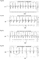
- FIGS. 4A to 4D are diagrams showing determination results of the heart failure stage. Specifically, in FIGS. 4A to 4D , first electrocardiograms 311, 321, 331, 341 are read out by the reading unit 111, and the determination results 312, 322, 332, 342 of the heart failure stage determined by the determination unit 112 are displayed based on the read out first electrocardiograms 311, 321, 331, 341 and the reference information.
- the NYHA corresponding to the determination result 312 shows 0 in all 9 heartbeats, which indicates a case of a healthy person.
- the NYHA corresponding to the determination result 322 shows 1 in all 9 heartbeats, which indicates a case where the heart failure stage is early.
- the NYHA corresponding to the determination result 332 shows 2 in all 11 heartbeats, which indicates a case where the heart failure stage is mild.
- the NYHA corresponding to the determination result 342 shows 2 for the third heartbeat out of 8 heartbeats, but 4 for the other 7 heartbeats, and since 4 is dominant, this indicates a case where the heart failure stage is moderately severe.
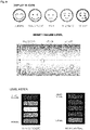
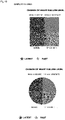
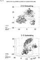
- FIGS. 5 to 14 Various screen examples displayed on the display unit 130 of the information processing system 100 or a second user terminal 220 described below are shown in FIGS. 5 to 14 for reference. According to the screen examples shown in FIGS. 5 to 14 , the user can easily grasp the determination results of the heart failure stage.
- the information processing method is configured to execute the reading step and the determination step.
- the reading step reads out the input first electrocardiogram.
- the determination step determines the heart failure stage based on the first electrocardiogram and the reference information.
- the reference information is information indicating a relationship between the second electrocardiogram and the feature quantity of the heart failure.
- the heart failure stage can be automatically determined. That is, since there is no need to obtain various information from the user, the labor of medical staff in determining the heart failure stage can be reduced.
- the second embodiment will be illustrated hereinafter.
- the description of the parts that overlap with the first embodiment will be appropriately omitted.
- the first electrocardiogram is preferably configured of 1 to 50 beats. Specifically, for example, it is 1, 2, 3, 4, 5, 6, 7, 8, 9, 10, 11, 12, 13, 14, 15, 16, 17, 18, 19, 20, 21, 22, 23, 24, 25, 26, 27, 28, 29, 30, 31, 32, 33, 34, 35, 36, 37, 38, 39, 40, 41, 42, 43, 44, 45, 46, 47, 48, 49, 50 beats, and may be in a range between any two of the numerical values illustrated above. In particular, it is preferably one beat.
- the determination unit 112 determines the heart failure stage based on the first electrocardiogram configured of 1 to 50 beats and the reference information.
- the first electrocardiogram is preferably configured of heartbeats of 5 to 300 seconds. Specifically, for example, it is 5, 10, 15, 20, 25, 30, 35, 40, 45, 50, 55, 60, 65, 70, 75, 80, 85, 90, 95, 100, 105, 110, 115, 120, 125, 130, 135, 140, 145, 150, 155, 160, 165, 170, 175, 180, 185, 190, 195, 200, 205, 210, 215, 220, 225, 230, 235, 240, 245, 250, 255, 260, 265, 270, 275, 280, 285, 290, 295, 300 seconds, and may be in the range between any two of the numerical values illustrated above. In particular, it is preferably 5 seconds.
- the determination unit 112 determines the heart failure stage based on the first electrocardiogram configured of heartbeats of 5 to 300 seconds and the reference information.
- the heart failure stage can be automatically determined if the first electrocardiogram indicating 1 to 50 beats and heartbeats of 5 to 300 seconds exists. Therefore, the time to obtain the first electrocardiogram can be reduced, and the heart failure stage can be determined quickly.
- the third embodiment will be illustrated hereinafter.
- the description of the parts that overlap with the first and second embodiments will be appropriately omitted.
- the first electrocardiogram is preferably configured of one lead.
- the determination unit 112 determines the heart failure stage based on the first electrocardiogram configured of the one lead and the reference information.
- the first electrocardiogram is usually configured of 6 types of limb leads and 6 types of chest leads, and the one lead indicates any one of these leads.
- the heart failure stage can be automatically determined if the first electrocardiogram regarding the one lead exists. That is, since the labor for attaching electrodes to the user can be eliminated, the labor of medical staff can be reduced.
- the fourth embodiment will be illustrated hereinafter.
- the description of the parts that overlap with the first, second and third embodiments will be appropriately omitted.
- FIG. 15 is a block diagram showing the functional structure of the information processing system 100.
- the reference information stored in the storage unit 120 is a learned model 122 in which the feature quantity of heart failure is learned from the second electrocardiogram.
- the learned model 122 is, for example, a learned model in which the feature quantity of heart failure is learned from the second electrocardiogram by deep learning or machine learning such as CNN (Convolutional Neural Network).
- FIG. 16A is an activity diagram showing a generation method of the learned model 122.
- machine learning will be illustrated as an example.
- the controller 110 e.g., CPU
- the controller 110 reads out the second electrocardiogram stored in the storage unit 120 (e.g., HDD) (A210).
- the controller 110 e.g., GPU
- the controller 110 performs machine learning regarding the second electrocardiogram (A220).
- the controller 110 e.g., GPU
- the output processing A230
- the learned model 122 is generated by repeatedly performing A210 to A230.
- the learned model is a model that learned a content determined in the determination unit 112 and corresponding clinical data.
- the clinical data is data including at least one of age, gender, BMI (Body Mass Index), PWTT (Pulse Wave Transit Time), blood pressure, heart rate, SDNN (Standard Deviation of The NN Interval), CVRR (Coefficient of Variation of RR Interval), atrial fibrillation, or HRV (Heart Rate Variability).
- FIG. 16B is an activity diagram showing information processing of the controller 110.
- the reading unit 111 reads out the input first electrocardiogram (A120).
- the determination unit 112 determines the heart failure stage based on the first electrocardiogram and the reference information (A140).
- the controller 110 causes the learned model 122 to machine learn the content determined in A140 and corresponding clinical data (A150).
- the heart failure stage can be determined with a high degree of accuracy by further learning the content determined in the determination unit 112 and corresponding clinical data.
- the fifth embodiment will be illustrated hereinafter.
- the description of the parts that overlap with the first, second, third and fourth embodiments will be appropriately omitted.
- FIG. 17 is a block diagram showing the functional structure of the information processing system 100.
- the controller 110 is preferably further comprises a preprocessor 113.
- the preprocessor 113 is specifically realized by hardware (the controller 110) with information processing by software (stored in the storage unit 120).
- the preprocessor 113 is configured to execute a preprocessing step.
- the preprocessor 113 preprocesses the first electrocardiogram read out by the reading unit 111.
- to preprocess indicates, for example, that a predetermined parameter necessary for removing noise in the first electrocardiogram are stored in the storage unit 120 (e.g., ROM or HDD) in advance, and that the controller 110 reads out the first electrocardiogram and the predetermined parameter from the storage unit 120 and performs processing.
- the preprocessing may include, for example, trend removal, motion artifact removal, noise removal, waveform cutout for each heartbeat, and normalization. These may be combined with each other for preprocessing.
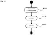
- FIG. 18 is an activity diagram showing the information processing of the controller 110.
- the reading unit 111 reads out the input first electrocardiogram (A120).
- the preprocessor 113 preprocesses the first electrocardiogram (A130).
- the determination unit 112 determines the heart failure stage based on the preprocessed first electrocardiogram and the reference information (A140).
- the heart failure stage can be determined with a high degree of accuracy by preprocessing the first electrocardiogram to make it easier to determine the heart failure stage.
- the sixth embodiment will be illustrated hereinafter.
- the description of the parts that overlap with the first, second, third, fourth, and fifth embodiments will be appropriately omitted.
- the one lead is preferably a lead I.
- the lead I is obtained from a right hand and a left hand of the user and giving a view of the lateral wall of the left ventricle in the heart.
- the heart failure stage can be automatically determined if the first electrocardiogram for the lead I exists.
- the electrodes are attached only to the right hand and the left hand of the user, the labor for attaching electrodes to the user can be eliminated, thus the labor of medical staff can be reduced.
- the seventh embodiment will be illustrated hereinafter.
- the description of the parts that overlap with the first, second, third, fourth, fifth and sixth embodiments will be appropriately omitted.
- FIG. 19 is a block diagram showing the functional structure of the information processing system 100.
- the controller 110 is preferably further comprises a reception unit 115 and a visual information generation unit 116.
- the reception unit 115 is specifically realized by hardware (the controller 110) with information processing by software (stored in the storage unit 120).
- the reception unit 115 is configured to execute a reception step.
- the reception unit 115 receives the first electrocardiogram from a first user terminal 210.
- the first user terminal 210 is, for example, a simple electrocardiograph, a wearable terminal, a 12-lead electrocardiograph, a bedside monitor, or a Holter electrocardiograph.
- to receive indicates, for example, receiving the first electrocardiogram obtained in the first user terminal 210 via the communication unit 150.
- the visual information generation unit 116 is specifically realized by hardware (the controller 110) with information processing by software (stored in the storage unit 120).
- the visual information generation unit 116 is configured to execute a visual information generation step.
- the visual information generation unit 116 generates visual information that can be seen by the second user terminal 220 from a result of the determination unit 112.
- the second user terminal 220 may be, for example, a computer, a smart phone, or a tablet.
- to generate the visual information indicates, for example, generating visual information such as screen, image, rendering information, or the like when displaying the results of the heart failure stage determination stored in the storage unit 120 (e.g., RAM or HDD) on the second user terminal 220.
- the first user terminal 210 and the second user terminal 220 may be the same terminal.
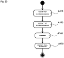
- FIG. 20 is an activity diagram showing the information processing of the controller 110.
- the reception unit 115 receives the first electrocardiogram from the first user terminal 210 (A110).
- the reading unit 111 reads out the input first electrocardiogram (A120).
- the determination unit 112 determines the heart failure stage based on the first electrocardiogram and the reference information (A140).
- the visual information generation unit 116 generates visual information that can be seen by the second user terminal 220 from the result determined in A140 (A170).
- the user can confirm the heart failure stage on his or her own second user terminal 220, thus the user can pay attention to his or her own physical condition without being constrained by time or place. In other words, it is possible to raise awareness of heart failure to the user.
- the clinical data is data including at least one of age, gender, BMI (Body Mass Index), PWTT (Pulse Wave Transit Time), blood pressure, heart rate, SDNN (Standard Deviation of The NN Interval), CVRR (Coefficient of Variation of RR Interval), atrial fibrillation, or HRV (Heart Rate Variability).
- the first electrocardiogram is configured of one lead.
- the one lead is a lead I, obtained from a right hand and a left hand of a user.
- a preprocessing step of preprocessing the first electrocardiogram read out in the reading step wherein the preprocessing is a processing for removing noise in the first electrocardiogram.
- the first electrocardiogram is configured of 1 to 50 beats.
- a reception step of accepting the first electrocardiogram from a first user terminal and a visual information generation step of generating visual information that can be seen by a second user terminal from a result of the determination step.
- a program wherein: the program allows a computer to execute each step of the information processing system.
Landscapes
- Health & Medical Sciences (AREA)
- Life Sciences & Earth Sciences (AREA)
- Engineering & Computer Science (AREA)
- Cardiology (AREA)
- Medical Informatics (AREA)
- Public Health (AREA)
- General Health & Medical Sciences (AREA)
- Biomedical Technology (AREA)
- Pathology (AREA)
- Physics & Mathematics (AREA)
- Animal Behavior & Ethology (AREA)
- Biophysics (AREA)
- Heart & Thoracic Surgery (AREA)
- Molecular Biology (AREA)
- Surgery (AREA)
- Veterinary Medicine (AREA)
- Physiology (AREA)
- Primary Health Care (AREA)
- Epidemiology (AREA)
- Data Mining & Analysis (AREA)
- Databases & Information Systems (AREA)
- Pulmonology (AREA)
- Vascular Medicine (AREA)
- General Business, Economics & Management (AREA)
- General Physics & Mathematics (AREA)
- Theoretical Computer Science (AREA)
- Business, Economics & Management (AREA)
- Measurement And Recording Of Electrical Phenomena And Electrical Characteristics Of The Living Body (AREA)
- Medical Treatment And Welfare Office Work (AREA)
Abstract
Description
- The present invention relates to an information processing system and a program.
- A method of detecting heart failure has been disclosed in which the electrocardiogram, heart rate, heart rate variability, heart rate interval, and respiratory frequency are obtained from the user, and information thereof is analyzed to determine whether or not the user has heart failure (see Patent Document 1).
- [Patent Document 1]
JP 2020-039472 - However, the technology disclosed in
Patent Document 1 does not determine the severity of the heart failure (heart failure stage). Further, since various information needed to be obtained from the user, it is time-consuming to determine the heart failure. - The present invention has been in view of the above circumstances and provides an information processing system capable of reducing labor of medical staff in determining the heart failure stage. Means for Solving Problems
- According to one aspect of the present invention, an information processing system is provided. The information processing system is configured to execute: a reading step of reading out an input first electrocardiogram including an electrocardiogram of a user; and a determination step of determining a heart failure stage of the user based on the first electrocardiogram and reference information, wherein the reference information is information showing a relationship between the second electrocardiogram, including the electrocardiogram obtained beforehand, in which the heart failure stage has been determined by the physician, and a feature quantity of the heart failure, wherein: the reference information is a learned model in which the feature quantity of the heart failure is learned from the second electrocardiogram, and the learned model is a model that learned a content determined in the determination step and corresponding clinical data.
- According to the above disclosure, it is possible to provide an information processing system capable of reducing labor of medical staff in determining the heart failure stage.
-
-
FIG. 1 is a block diagram showing a configuration of aninformation processing system 100. -
FIG. 2 is a block diagram showing a functional structure of theinformation processing system 100. -
FIG. 3 is an activity diagram showing information processing of acontroller 110. -
FIG. 4A is a diagram showing the normalized electrocardiogram and heart failure stage of a healthy person.Figure 4B is a diagram showing the normalized electrocardiogram and heart failure stage at early stage.FIG. 4C is a diagram showing the normalized electrocardiogram and heart failure stage in mild.FIG. 4D is a diagram showing the normalized electrocardiogram and heart failure stage in moderately severe. -
FIG. 5 is a diagram showing a representation method of a determination result of the heart failure stage. -
FIG. 6 is a diagram showing a representation method of a determination result of the heart failure stage. -
FIG. 7 is a diagram showing a representation method of a determination result of the heart failure stage. -
FIG. 8 is a diagram showing a representation method of a determination result of the heart failure stage. -
FIG. 9 is a diagram showing a representation method of a determination result of the heart failure stage. -
FIG. 10 is a diagram showing a representation method of a determination result of the heart failure stage. -
FIG. 11 is a diagram showing a representation method of a determination result of the heart failure stage. -
FIG. 12 is a diagram showing a representation method of a determination result of the heart failure stage. -
FIG. 13 is a diagram showing a representation method of a determination result of the heart failure stage. -
FIG. 14 is a diagram showing a representation method of a determination result of the heart failure stage. -
FIG. 15 is a block diagram showing the functional structure of theinformation processing system 100. -
FIG. 16A is an activity diagram showing a generation method of a learnedmodel 122.FIG. 16B is an activity diagram showing information processing of acontroller 110. -
FIG. 17 is a block diagram showing the functional structure of theinformation processing system 100. -
FIG. 18 is an activity diagram showing the information processing of thecontroller 110. -
FIG. 19 is a block diagram showing the functional structure of theinformation processing system 100. -
FIG. 20 is an activity diagram showing the information processing of thecontroller 110. - Hereinafter, embodiments of the present invention will be described with reference to the drawings. Various features described in the embodiment below can be combined with each other.
- A program for realizing a software in the present embodiment may be provided as a non-transitory computer readable medium that can be read by a computer, or may be provided for download from an external server, or may be provided so that the program can be activated on an external computer to realize its functions on a client terminal (so-called cloud computing).
- In the present embodiment, the "unit" may include, for instance, a combination of hardware resources implemented by circuits in a broad sense and information processing of software that can be concretely realized by these hardware resources. Further, although various information is performed in the present embodiment, this information can be represented, for example, by physical signal values representing voltage and current, by high and low signal values as a bit set of binary numbers composed of 0 or 1, or by quantum superposition (so-called quantum bits). In this way, communication/calculation can be performed on a circuit in a broad sense.
- Further, the circuit in a broad sense is a circuit realized by combining at least an appropriate number of a circuit, a circuitry, a processor, a memory, and the like. In other words, it is a circuit includes Application Specific Integrated Circuit (ASIC), Programmable Logic Device (e.g., Simple Programmable Logic Device (SPLD), Complex Programmable Logic Device (CPLD), and Field Programmable Gate Array (FPGA)), and the like.
- The first embodiment will be described as follows.
-
FIG. 1 is a block diagram showing a configuration of aninformation processing system 100. As shown inFIG. 1 , theinformation processing system 100 has acontroller 110, astorage unit 120, adisplay unit 130, aninput unit 140, and acommunication unit 150. Thecontroller 110 is a CPU (Central Processing Unit), GPU (Graphics Processing Unit), or the like, and controls the entireinformation processing system 100. Thestorage unit 120 stores various programs and data, and is configured of, for example, memory, HDD (Hard Disk Drive), ROM (Read Only Memory), RAM (Random Access Memory), and the like. - The
storage unit 120 stores data or the like used when thecontroller 110 executes processing based on the program. By executing processing by thecontroller 110 based on the program stored in thestorage unit 120, various processing described below are realized. In other words, the program causes the computer to execute each step of theinformation processing system 100. As for thestorage unit 120, at least a part of the information may be stored in an external server other than thestorage unit 120, or may be stored in a plurality of terminals in a distributed manner using blockchain technology or the like. - The
display unit 130 displays text or images (including still and moving images) and is configured with any display. Theinput unit 140 inputs various information to theinformation processing system 100, and is configured of mouse, keyboard, pointing device, and the like. Thecommunication unit 150 is a NIC (Network Interface Card) or the like, and connects theinformation processing system 100 to a network, and is configured to enable data communication with other device or component through wired or wireless connection. -
FIG. 2 is a block diagram showing a functional structure of theinformation processing system 100. As shown inFIG. 2 , thecontroller 110 comprises areading unit 111 and adetermination unit 112. Thereading unit 111 is a unit in which information processing by a software (stored in the storage unit 120) is specifically realized by a hardware (the controller 110). Thereading unit 111 is configured to execute the reading step. Thereading unit 111 reads out the input first electrocardiogram. The first electrocardiogram indicates the electrocardiogram obtained from the user. Reading out the first electrocardiogram means, for example, receiving the first electrocardiogram from an external device via thecommunication unit 150, writing to the storage unit 120 (e.g., RAM) by reading out the first electrocardiogram, reading out the first electrocardiogram stored in the storage unit 120 (e.g., HDD) beforehand in response to an operation of theinput unit 140 by the user, and writing to the storage unit 120 (e.g., RAM), or writing the first electrocardiogram transmitted from a predetermined electrocardiogram measurement terminal to a cloud and stored in a storage apparatus (e.g., HDD) of a server to a storage apparatus (e.g., RAM) of a server by a control apparatus (e.g., CPU) of the server, or the like. Of course, these are only examples and are not limited to these. - The
determination unit 112 is a unit in which information processing by the software (stored in the storage unit 120) is specifically realized by the hardware (the controller 110). Thedetermination unit 112 is configured to perform a determination step. Thedetermination unit 112 determines the heart failure stage based on the first electrocardiogram and thereference information 121. Thereference information 121 is stored in the storage unit 120 (e.g., ROM). Here, thereference information 121 is information that indicates the relationship between the second electrocardiogram and a feature quantity of the heart failure. Examples of the reference information include look-up table, function, mathematical model, learned model, or the like. Of course, these are only examples and are not limited to these. The heart failure stage refers to a four-stage classification of heart failure severity based on the degree of subjective symptoms caused by physical activity, created by NYHA (New York Heart Association). Moreover, the second electrocardiogram indicates the electrocardiogram that has been obtained in advance and for which the heart failure stage has been determined by a physician. - Here, to determine means, for example, that a look-up table is stored in the storage unit 120 (e.g., ROM or HDD) in advance and the
controller 110 reads out the look-up table from thestorage unit 120 to determine, that a function is stored in the storage unit 120 (e.g., ROM or HDD) in advance and the decision is made by inputting the feature quantity obtained from the first electrocardiogram to the function, that a mathematical model is stored in the storage unit 120 (e.g., ROM or HDD) in advance and the decision is made by inputting the feature quantity obtained from the first electrocardiogram to the mathematical model, or the decision is made by inputting the feature quantity obtained from the first electrocardiogram to the learned model based on the learned model that learned the second electrocardiogram and the feature quantity of the heart failure. Of course, these are only examples and are not limited to these. -
FIG. 3 is an activity diagram showing information processing of thecontroller 110. As shown inFIG. 3 , thereading unit 111 reads out the input first electrocardiogram (A120). Next, thedetermination unit 112 determines the heart failure stage based on the first electrocardiogram and the reference information (A140). -
FIGS. 4A to 4D are diagrams showing determination results of the heart failure stage. Specifically, inFIGS. 4A to 4D ,first electrocardiograms reading unit 111, and the determination results 312, 322, 332, 342 of the heart failure stage determined by thedetermination unit 112 are displayed based on the read outfirst electrocardiograms - As shown in
FIG. 4A , the NYHA corresponding to thedetermination result 312shows 0 in all 9 heartbeats, which indicates a case of a healthy person. As shown inFIG. 4B , the NYHA corresponding to thedetermination result 322shows 1 in all 9 heartbeats, which indicates a case where the heart failure stage is early. As shown inFIG. 4C , the NYHA corresponding to thedetermination result 332shows 2 in all 11 heartbeats, which indicates a case where the heart failure stage is mild. As shown inFIG. 4D , the NYHA corresponding to thedetermination result 342shows 2 for the third heartbeat out of 8 heartbeats, but 4 for the other 7 heartbeats, and since 4 is dominant, this indicates a case where the heart failure stage is moderately severe. - Various screen examples displayed on the
display unit 130 of theinformation processing system 100 or asecond user terminal 220 described below are shown inFIGS. 5 to 14 for reference. According to the screen examples shown inFIGS. 5 to 14 , the user can easily grasp the determination results of the heart failure stage. - In summary, the information processing method is configured to execute the reading step and the determination step.
- The reading step reads out the input first electrocardiogram. The determination step determines the heart failure stage based on the first electrocardiogram and the reference information. The reference information is information indicating a relationship between the second electrocardiogram and the feature quantity of the heart failure.
- In the first embodiment, if the input first electrocardiogram exists, the heart failure stage can be automatically determined. That is, since there is no need to obtain various information from the user, the labor of medical staff in determining the heart failure stage can be reduced.
- The second embodiment will be illustrated hereinafter. In the second embodiment, the description of the parts that overlap with the first embodiment will be appropriately omitted.
- The first electrocardiogram is preferably configured of 1 to 50 beats. Specifically, for example, it is 1, 2, 3, 4, 5, 6, 7, 8, 9, 10, 11, 12, 13, 14, 15, 16, 17, 18, 19, 20, 21, 22, 23, 24, 25, 26, 27, 28, 29, 30, 31, 32, 33, 34, 35, 36, 37, 38, 39, 40, 41, 42, 43, 44, 45, 46, 47, 48, 49, 50 beats, and may be in a range between any two of the numerical values illustrated above. In particular, it is preferably one beat. The
determination unit 112 determines the heart failure stage based on the first electrocardiogram configured of 1 to 50 beats and the reference information. - The first electrocardiogram is preferably configured of heartbeats of 5 to 300 seconds. Specifically, for example, it is 5, 10, 15, 20, 25, 30, 35, 40, 45, 50, 55, 60, 65, 70, 75, 80, 85, 90, 95, 100, 105, 110, 115, 120, 125, 130, 135, 140, 145, 150, 155, 160, 165, 170, 175, 180, 185, 190, 195, 200, 205, 210, 215, 220, 225, 230, 235, 240, 245, 250, 255, 260, 265, 270, 275, 280, 285, 290, 295, 300 seconds, and may be in the range between any two of the numerical values illustrated above. In particular, it is preferably 5 seconds. The
determination unit 112 determines the heart failure stage based on the first electrocardiogram configured of heartbeats of 5 to 300 seconds and the reference information. - In the second embodiment, the heart failure stage can be automatically determined if the first electrocardiogram indicating 1 to 50 beats and heartbeats of 5 to 300 seconds exists. Therefore, the time to obtain the first electrocardiogram can be reduced, and the heart failure stage can be determined quickly.
- The third embodiment will be illustrated hereinafter. In the third embodiment, the description of the parts that overlap with the first and second embodiments will be appropriately omitted.
- The first electrocardiogram is preferably configured of one lead. The
determination unit 112 determines the heart failure stage based on the first electrocardiogram configured of the one lead and the reference information. The first electrocardiogram is usually configured of 6 types of limb leads and 6 types of chest leads, and the one lead indicates any one of these leads. - In the third embodiment, the heart failure stage can be automatically determined if the first electrocardiogram regarding the one lead exists. That is, since the labor for attaching electrodes to the user can be eliminated, the labor of medical staff can be reduced.
- The fourth embodiment will be illustrated hereinafter. In the fourth embodiment, the description of the parts that overlap with the first, second and third embodiments will be appropriately omitted.
-
FIG. 15 is a block diagram showing the functional structure of theinformation processing system 100. As shown inFIG. 15 , it is preferable that the reference information stored in thestorage unit 120 is a learnedmodel 122 in which the feature quantity of heart failure is learned from the second electrocardiogram. The learnedmodel 122 is, for example, a learned model in which the feature quantity of heart failure is learned from the second electrocardiogram by deep learning or machine learning such as CNN (Convolutional Neural Network). -
FIG. 16A is an activity diagram showing a generation method of the learnedmodel 122. Here, machine learning will be illustrated as an example. As shown inFIG. 16A , the controller 110 (e.g., CPU) reads out the second electrocardiogram stored in the storage unit 120 (e.g., HDD) (A210). Next, the controller 110 (e.g., GPU) performs machine learning regarding the second electrocardiogram (A220). Then, the controller 110 (e.g., GPU) performs the output processing (A230). Here, the learnedmodel 122 is generated by repeatedly performing A210 to A230. - Here, the learned model is a model that learned a content determined in the
determination unit 112 and corresponding clinical data. The clinical data is data including at least one of age, gender, BMI (Body Mass Index), PWTT (Pulse Wave Transit Time), blood pressure, heart rate, SDNN (Standard Deviation of The NN Interval), CVRR (Coefficient of Variation of RR Interval), atrial fibrillation, or HRV (Heart Rate Variability). -
FIG. 16B is an activity diagram showing information processing of thecontroller 110. As shown inFIG. 16B , thereading unit 111 reads out the input first electrocardiogram (A120). Next, thedetermination unit 112 determines the heart failure stage based on the first electrocardiogram and the reference information (A140). Then, thecontroller 110 causes the learnedmodel 122 to machine learn the content determined in A140 and corresponding clinical data (A150). - In the fourth embodiment, by using the learned
model 122 as reference information, the heart failure stage can be determined with a high degree of accuracy by further learning the content determined in thedetermination unit 112 and corresponding clinical data. - The fifth embodiment will be illustrated hereinafter. In the fifth embodiment, the description of the parts that overlap with the first, second, third and fourth embodiments will be appropriately omitted.
-
FIG. 17 is a block diagram showing the functional structure of theinformation processing system 100. - As shown in
FIG. 17 , thecontroller 110 is preferably further comprises apreprocessor 113. Thepreprocessor 113 is specifically realized by hardware (the controller 110) with information processing by software (stored in the storage unit 120). Thepreprocessor 113 is configured to execute a preprocessing step. Thepreprocessor 113 preprocesses the first electrocardiogram read out by thereading unit 111. Here, to preprocess indicates, for example, that a predetermined parameter necessary for removing noise in the first electrocardiogram are stored in the storage unit 120 (e.g., ROM or HDD) in advance, and that thecontroller 110 reads out the first electrocardiogram and the predetermined parameter from thestorage unit 120 and performs processing. The preprocessing may include, for example, trend removal, motion artifact removal, noise removal, waveform cutout for each heartbeat, and normalization. These may be combined with each other for preprocessing. -
FIG. 18 is an activity diagram showing the information processing of thecontroller 110. As shown inFIG. 18 , thereading unit 111 reads out the input first electrocardiogram (A120). Next, thepreprocessor 113 preprocesses the first electrocardiogram (A130). Then, thedetermination unit 112 determines the heart failure stage based on the preprocessed first electrocardiogram and the reference information (A140). - In the fifth embodiment, the heart failure stage can be determined with a high degree of accuracy by preprocessing the first electrocardiogram to make it easier to determine the heart failure stage.
- The sixth embodiment will be illustrated hereinafter. In the sixth embodiment, the description of the parts that overlap with the first, second, third, fourth, and fifth embodiments will be appropriately omitted.
- The one lead is preferably a lead I. Here, the lead I is obtained from a right hand and a left hand of the user and giving a view of the lateral wall of the left ventricle in the heart.
- In the sixth embodiment, the heart failure stage can be automatically determined if the first electrocardiogram for the lead I exists. In other words, since the electrodes are attached only to the right hand and the left hand of the user, the labor for attaching electrodes to the user can be eliminated, thus the labor of medical staff can be reduced.
- The seventh embodiment will be illustrated hereinafter. In the seventh embodiment, the description of the parts that overlap with the first, second, third, fourth, fifth and sixth embodiments will be appropriately omitted.
-
FIG. 19 is a block diagram showing the functional structure of theinformation processing system 100. As shown inFIG. 19 , thecontroller 110 is preferably further comprises areception unit 115 and a visualinformation generation unit 116. Thereception unit 115 is specifically realized by hardware (the controller 110) with information processing by software (stored in the storage unit 120). Thereception unit 115 is configured to execute a reception step. Thereception unit 115 receives the first electrocardiogram from afirst user terminal 210. Thefirst user terminal 210 is, for example, a simple electrocardiograph, a wearable terminal, a 12-lead electrocardiograph, a bedside monitor, or a Holter electrocardiograph. Here, to receive indicates, for example, receiving the first electrocardiogram obtained in thefirst user terminal 210 via thecommunication unit 150. - The visual
information generation unit 116 is specifically realized by hardware (the controller 110) with information processing by software (stored in the storage unit 120). The visualinformation generation unit 116 is configured to execute a visual information generation step. The visualinformation generation unit 116 generates visual information that can be seen by thesecond user terminal 220 from a result of thedetermination unit 112. Thesecond user terminal 220 may be, for example, a computer, a smart phone, or a tablet. Here, to generate the visual information indicates, for example, generating visual information such as screen, image, rendering information, or the like when displaying the results of the heart failure stage determination stored in the storage unit 120 (e.g., RAM or HDD) on thesecond user terminal 220. Thefirst user terminal 210 and thesecond user terminal 220 may be the same terminal. -
FIG. 20 is an activity diagram showing the information processing of thecontroller 110. As shown inFIG. 20 , thereception unit 115 receives the first electrocardiogram from the first user terminal 210 (A110). Next, thereading unit 111 reads out the input first electrocardiogram (A120). Then, thedetermination unit 112 determines the heart failure stage based on the first electrocardiogram and the reference information (A140). Next, the visualinformation generation unit 116 generates visual information that can be seen by thesecond user terminal 220 from the result determined in A140 (A170). - In the seventh embodiment, the user can confirm the heart failure stage on his or her own
second user terminal 220, thus the user can pay attention to his or her own physical condition without being constrained by time or place. In other words, it is possible to raise awareness of heart failure to the user. - It may be provided in each of the following aspects.
- In the information processing system, the clinical data is data including at least one of age, gender, BMI (Body Mass Index), PWTT (Pulse Wave Transit Time), blood pressure, heart rate, SDNN (Standard Deviation of The NN Interval), CVRR (Coefficient of Variation of RR Interval), atrial fibrillation, or HRV (Heart Rate Variability).
- In the information processing system, the first electrocardiogram is configured of one lead.
- In the information processing system, the one lead is a lead I, obtained from a right hand and a left hand of a user.
- In the information processing system, a preprocessing step of preprocessing the first electrocardiogram read out in the reading step, wherein the preprocessing is a processing for removing noise in the first electrocardiogram.
- In the information processing system, the first electrocardiogram is configured of 1 to 50 beats.
- In the information processing system, a reception step of accepting the first electrocardiogram from a first user terminal, and a visual information generation step of generating visual information that can be seen by a second user terminal from a result of the determination step.
- A program, wherein: the program allows a computer to execute each step of the information processing system.
- Of course, the above embodiments are not limited thereto.
-
- 100:
- Information processing system
- 110:
- Controller
- 111:
- Reading unit
- 112:
- Determination unit
- 113:
- Preprocessor
- 115:
- Reception unit
- 116:
- Visual information generation unit
- 120:
- Storage unit
- 121:
- Reference information
- 122:
- Learned model
- 130:
- Display unit
- 140:
- Input unit
- 150:
- Communication unit
- 210:
- First user terminal
- 220:
- Second user terminal
- 311:
- First electrocardiogram
- 312:
- Determination result
- 321:
- First electrocardiogram
- 322:
- Determination result
- 331:
- First electrocardiogram
- 332:
- Determination result
- 341:
- First electrocardiogram
- 342:
- Determination result
Claims (8)
- An information processing system, configured to execute:a reading step of reading out an input first electrocardiogram including an electrocardiogram of a user; anda determination step of determining a heart failure stage of the user based on the first electrocardiogram and reference information, wherein the reference information is information showing a relationship between the second electrocardiogram, including the electrocardiogram obtained beforehand, in which the heart failure stage has been determined by the physician, and a feature quantity of the heart failure, wherein:the reference information is a learned model in which the feature quantity of the heart failure is learned from the second electrocardiogram, andthe learned model is a model that learned a content determined in the determination step and corresponding clinical data.
- The information processing system according to Claim 1, wherein:
the clinical data is data including at least one of age, gender, BMI (Body Mass Index), PWTT (Pulse Wave Transit Time), blood pressure, heart rate, SDNN (Standard Deviation of The NN Interval), CVRR (Coefficient of Variation of RR Interval), atrial fibrillation, or HRV (Heart Rate Variability). - The information processing system according to Claim 1, wherein:
the first electrocardiogram is configured of one lead. - The information processing system according to Claim 3, wherein:
the one lead is a lead I, obtained from a right hand and a left hand of a user. - The information processing system according to Claim 1, further configured to execute:
a preprocessing step of preprocessing the first electrocardiogram read out in the reading step, wherein the preprocessing is a processing for removing noise in the first electrocardiogram. - The information processing system according to Claim 1, wherein:
the first electrocardiogram is configured of 1 to 50 beats. - The information processing system according to Claim 1, further configured to execute:a reception step of accepting the first electrocardiogram from a first user terminal, anda visual information generation step of generating visual information that can be seen by a second user terminal from a result of the determination step.
- A program, wherein:
the program allows a computer to execute each step of the information processing system according to Claim 1.
Priority Applications (1)
| Application Number | Priority Date | Filing Date | Title |
|---|---|---|---|
| EP24197438.5A EP4446995A3 (en) | 2020-08-31 | 2021-06-21 | Information processing system and program |
Applications Claiming Priority (2)
| Application Number | Priority Date | Filing Date | Title |
|---|---|---|---|
| JP2020145822A JP6893002B1 (en) | 2020-08-31 | 2020-08-31 | Information processing system and program |
| PCT/JP2021/023417 WO2022044509A1 (en) | 2020-08-31 | 2021-06-21 | Information processing system and program |
Related Child Applications (1)
| Application Number | Title | Priority Date | Filing Date |
|---|---|---|---|
| EP24197438.5A Division EP4446995A3 (en) | 2020-08-31 | 2021-06-21 | Information processing system and program |
Publications (2)
| Publication Number | Publication Date |
|---|---|
| EP3981316A1 true EP3981316A1 (en) | 2022-04-13 |
| EP3981316A4 EP3981316A4 (en) | 2022-06-29 |
Family
ID=76464601
Family Applications (2)
| Application Number | Title | Priority Date | Filing Date |
|---|---|---|---|
| EP21773262.7A Ceased EP3981316A4 (en) | 2020-08-31 | 2021-06-21 | Information processing system and program |
| EP24197438.5A Withdrawn EP4446995A3 (en) | 2020-08-31 | 2021-06-21 | Information processing system and program |
Family Applications After (1)
| Application Number | Title | Priority Date | Filing Date |
|---|---|---|---|
| EP24197438.5A Withdrawn EP4446995A3 (en) | 2020-08-31 | 2021-06-21 | Information processing system and program |
Country Status (5)
| Country | Link |
|---|---|
| US (1) | US11412978B2 (en) |
| EP (2) | EP3981316A4 (en) |
| JP (1) | JP6893002B1 (en) |
| CN (2) | CN117838067A (en) |
| WO (1) | WO2022044509A1 (en) |
Families Citing this family (7)
| Publication number | Priority date | Publication date | Assignee | Title |
|---|---|---|---|---|
| JP7075611B1 (en) * | 2021-10-28 | 2022-05-26 | 国立大学法人 東京大学 | Information processing equipment, programs and information processing methods |
| JP7855900B2 (en) * | 2022-03-31 | 2026-05-11 | オムロンヘルスケア株式会社 | Medical support systems, medical support devices, and programs |
| JP2025512817A (en) * | 2022-04-08 | 2025-04-22 | 3 エイム アイピー プロプライエトリー リミテッド | Devices and methods for detecting and monitoring cardiovascular disease - Patents.com |
| WO2024038618A1 (en) | 2022-08-19 | 2024-02-22 | 株式会社UT−Heart研究所 | Method for utilizing in-silico heart disease database, program for utilizing in-silico heart disease database, and information processing device |
| WO2024167018A1 (en) | 2023-02-10 | 2024-08-15 | 公立大学法人横浜市立大学 | Heart failure estimation device, heart failure estimation system, heart failure estimation method, and heart failure estimation program |
| WO2024191246A1 (en) * | 2023-03-13 | 2024-09-19 | 주식회사 메디컬에이아이 | Method, program, and device for prognosis of heart failure |
| JPWO2025095008A1 (en) * | 2023-10-30 | 2025-05-08 |
Family Cites Families (13)
| Publication number | Priority date | Publication date | Assignee | Title |
|---|---|---|---|---|
| JP2003153864A (en) * | 2001-11-26 | 2003-05-27 | Nippon Koden Corp | Electronic medical record system |
| US8768718B2 (en) * | 2006-12-27 | 2014-07-01 | Cardiac Pacemakers, Inc. | Between-patient comparisons for risk stratification of future heart failure decompensation |
| CN102176861B (en) * | 2008-10-10 | 2015-11-25 | 心脏起搏器公司 | For the multi-sensor strategy of heart failure patient management |
| JP5356961B2 (en) * | 2009-09-17 | 2013-12-04 | フクダ電子株式会社 | Medical information service provision device |
| CN103038772B (en) * | 2010-03-15 | 2017-10-24 | 新加坡保健服务集团有限公司 | Systems and devices for predicting patient survivability |
| US10893824B2 (en) * | 2010-12-20 | 2021-01-19 | Cardiac Pacemakers, Inc. | Heart failure detection with a sequential classifier |
| CN102670190A (en) * | 2012-05-21 | 2012-09-19 | 南京大学 | Heart rate variability nonlinear characteristic-based automatic diagnosis method for congestive heart failure |
| JP2015231427A (en) * | 2014-06-09 | 2015-12-24 | 株式会社デンソー | Electrocardiograph |
| AU2016282695B2 (en) * | 2015-06-24 | 2018-11-15 | Cardiac Pacemakers, Inc. | Event detection using a variable threshold |
| US10772570B2 (en) * | 2015-09-18 | 2020-09-15 | Spangler Scientific Llc | Non?invasive prediction of risk for sudden cardiac death |
| US10932726B2 (en) * | 2018-03-16 | 2021-03-02 | Zoll Medical Corporation | Monitoring physiological status based on bio-vibrational and radio frequency data analysis |
| JP7161182B2 (en) * | 2018-09-07 | 2022-10-26 | 国立大学法人大阪大学 | Heart failure detection method and device, detection terminal device, heart failure detection support system, production method thereof, and computer program |
| US11246538B2 (en) * | 2019-03-20 | 2022-02-15 | Zoll Medical Corporation | Single channel and dual channel noise detection systems and techniques |
-
2020
- 2020-08-31 JP JP2020145822A patent/JP6893002B1/en active Active
-
2021
- 2021-06-21 CN CN202311635091.1A patent/CN117838067A/en active Pending
- 2021-06-21 WO PCT/JP2021/023417 patent/WO2022044509A1/en not_active Ceased
- 2021-06-21 CN CN202180002401.9A patent/CN114599272A/en active Pending
- 2021-06-21 EP EP21773262.7A patent/EP3981316A4/en not_active Ceased
- 2021-06-21 US US17/435,974 patent/US11412978B2/en active Active
- 2021-06-21 EP EP24197438.5A patent/EP4446995A3/en not_active Withdrawn
Also Published As
| Publication number | Publication date |
|---|---|
| JP6893002B1 (en) | 2021-06-23 |
| EP4446995A2 (en) | 2024-10-16 |
| EP3981316A4 (en) | 2022-06-29 |
| JP2022040892A (en) | 2022-03-11 |
| EP4446995A3 (en) | 2024-12-18 |
| US11412978B2 (en) | 2022-08-16 |
| CN114599272A (en) | 2022-06-07 |
| CN117838067A (en) | 2024-04-09 |
| US20220061754A1 (en) | 2022-03-03 |
| WO2022044509A1 (en) | 2022-03-03 |
Similar Documents
| Publication | Publication Date | Title |
|---|---|---|
| US11412978B2 (en) | Information processing system and program | |
| US12582315B2 (en) | Electrocardiogram analysis apparatus, electrocardiogram analyzing method, and non-transitory computer-readable storage medium | |
| JP7075611B1 (en) | Information processing equipment, programs and information processing methods | |
| CN116616790B (en) | Cardiac risk assessment method, apparatus, computer device and storage medium | |
| US20210204858A1 (en) | Automatic sensing of features within an electrocardiogram | |
| CN116504398A (en) | Method and system for cardiac arrhythmia prediction using a transformer-based neural network | |
| KR102392760B1 (en) | Electrocardiogram data processing server, method for displaying analysis data of electrocardiogram signal, and computer program | |
| Shusterman et al. | Personalized ECG monitoring and adaptive machine learning | |
| WO2025035641A1 (en) | Electrocardiogram data analysis method and apparatus, and computer device and storage medium | |
| US8103065B2 (en) | Assessment of medical conditions | |
| JP7558556B2 (en) | Medical information processing device, medical information processing method, medical information processing program, and medical information processing system | |
| US11478199B2 (en) | Heart signal waveform processing system and method | |
| KR102392759B1 (en) | Electrocardiogram data processing server, method for handling analysis tasks for signal intervals that meet analysis condition, and computer program | |
| JP7522405B1 (en) | PROGRAM, INFORMATION PROCESSING METHOD AND INFORMATION PROCESSING SYSTEM | |
| JP7537826B2 (en) | Method and system for converting index values based on ECG signals - Patents.com | |
| KR102345009B1 (en) | Electrocardiogram data processing server, method for calculating expected analysis time required for electrocardiogram analysis, and computer program | |
| JP7479106B1 (en) | PROGRAM, OUTPUT DEVICE, AND OUTPUT METHOD | |
| CN113905667A (en) | Monitoring processing method and device and storage medium | |
| Azmi et al. | Monitoring Heart Condition of the Patient with ECG Sensor | |
| Shinde et al. | TinyML Based Detection of Alcohol Induced Abnormalities Using ECG Signals and Metadata | |
| US20200323457A1 (en) | Heartbeat analyzer |
Legal Events
| Date | Code | Title | Description |
|---|---|---|---|
| STAA | Information on the status of an ep patent application or granted ep patent |
Free format text: STATUS: UNKNOWN |
|
| STAA | Information on the status of an ep patent application or granted ep patent |
Free format text: STATUS: THE INTERNATIONAL PUBLICATION HAS BEEN MADE |
|
| PUAI | Public reference made under article 153(3) epc to a published international application that has entered the european phase |
Free format text: ORIGINAL CODE: 0009012 |
|
| STAA | Information on the status of an ep patent application or granted ep patent |
Free format text: STATUS: REQUEST FOR EXAMINATION WAS MADE |
|
| 17P | Request for examination filed |
Effective date: 20210929 |
|
| AK | Designated contracting states |
Kind code of ref document: A1 Designated state(s): AL AT BE BG CH CY CZ DE DK EE ES FI FR GB GR HR HU IE IS IT LI LT LU LV MC MK MT NL NO PL PT RO RS SE SI SK SM TR |
|
| REG | Reference to a national code |
Ref country code: DE Ref legal event code: R079 Free format text: PREVIOUS MAIN CLASS: H99Z9999999999 Ipc: G16H0050700000 |
|
| A4 | Supplementary search report drawn up and despatched |
Effective date: 20220527 |
|
| RIC1 | Information provided on ipc code assigned before grant |
Ipc: G06T 11/20 20060101ALI20220520BHEP Ipc: A61B 5/361 20210101ALI20220520BHEP Ipc: A61B 5/00 20060101ALI20220520BHEP Ipc: A61B 5/0205 20060101ALI20220520BHEP Ipc: A61B 5/352 20210101ALI20220520BHEP Ipc: A61B 5/339 20210101ALI20220520BHEP Ipc: A61B 5/271 20210101ALI20220520BHEP Ipc: A61B 5/024 20060101ALI20220520BHEP Ipc: A61B 5/021 20060101ALI20220520BHEP Ipc: G16H 70/60 20180101ALI20220520BHEP Ipc: G16H 40/63 20180101ALI20220520BHEP Ipc: G16H 50/20 20180101ALI20220520BHEP Ipc: G16H 50/70 20180101AFI20220520BHEP |
|
| STAA | Information on the status of an ep patent application or granted ep patent |
Free format text: STATUS: EXAMINATION IS IN PROGRESS |
|
| 17Q | First examination report despatched |
Effective date: 20230125 |
|
| DAV | Request for validation of the european patent (deleted) | ||
| DAX | Request for extension of the european patent (deleted) | ||
| APBN | Date of receipt of notice of appeal recorded |
Free format text: ORIGINAL CODE: EPIDOSNNOA2E |
|
| APAV | Appeal reference deleted |
Free format text: ORIGINAL CODE: EPIDOSDREFNE |
|
| APAF | Appeal reference modified |
Free format text: ORIGINAL CODE: EPIDOSCREFNE |
|
| APBR | Date of receipt of statement of grounds of appeal recorded |
Free format text: ORIGINAL CODE: EPIDOSNNOA3E |
|
| APAV | Appeal reference deleted |
Free format text: ORIGINAL CODE: EPIDOSDREFNE |
|
| REG | Reference to a national code |
Ref country code: DE Ref legal event code: R003 |
|
| APBT | Appeal procedure closed |
Free format text: ORIGINAL CODE: EPIDOSNNOA9E |
|
| STAA | Information on the status of an ep patent application or granted ep patent |
Free format text: STATUS: THE APPLICATION HAS BEEN REFUSED |
|
| 18R | Application refused |
Effective date: 20250924 |