EP3980833B1 - Diopter adjustment mechanism - Google Patents
Diopter adjustment mechanism Download PDFInfo
- Publication number
- EP3980833B1 EP3980833B1 EP20840681.9A EP20840681A EP3980833B1 EP 3980833 B1 EP3980833 B1 EP 3980833B1 EP 20840681 A EP20840681 A EP 20840681A EP 3980833 B1 EP3980833 B1 EP 3980833B1
- Authority
- EP
- European Patent Office
- Prior art keywords
- thread
- female thread
- pitch
- viewing optic
- female
- Prior art date
- Legal status (The legal status is an assumption and is not a legal conclusion. Google has not performed a legal analysis and makes no representation as to the accuracy of the status listed.)
- Active
Links
Images
Classifications
-
- G—PHYSICS
- G02—OPTICS
- G02B—OPTICAL ELEMENTS, SYSTEMS OR APPARATUS
- G02B23/00—Telescopes, e.g. binoculars; Periscopes; Instruments for viewing the inside of hollow bodies; Viewfinders; Optical aiming or sighting devices
- G02B23/16—Housings; Caps; Mountings; Supports, e.g. with counterweight
-
- F—MECHANICAL ENGINEERING; LIGHTING; HEATING; WEAPONS; BLASTING
- F16—ENGINEERING ELEMENTS AND UNITS; GENERAL MEASURES FOR PRODUCING AND MAINTAINING EFFECTIVE FUNCTIONING OF MACHINES OR INSTALLATIONS; THERMAL INSULATION IN GENERAL
- F16B—DEVICES FOR FASTENING OR SECURING CONSTRUCTIONAL ELEMENTS OR MACHINE PARTS TOGETHER, e.g. NAILS, BOLTS, CIRCLIPS, CLAMPS, CLIPS OR WEDGES; JOINTS OR JOINTING
- F16B33/00—Features common to bolt and nut
- F16B33/02—Shape of thread; Special thread-forms
-
- F—MECHANICAL ENGINEERING; LIGHTING; HEATING; WEAPONS; BLASTING
- F41—WEAPONS
- F41G—WEAPON SIGHTS; AIMING
- F41G1/00—Sighting devices
- F41G1/38—Telescopic sights specially adapted for smallarms or ordnance; Supports or mountings therefor
-
- G—PHYSICS
- G02—OPTICS
- G02B—OPTICAL ELEMENTS, SYSTEMS OR APPARATUS
- G02B23/00—Telescopes, e.g. binoculars; Periscopes; Instruments for viewing the inside of hollow bodies; Viewfinders; Optical aiming or sighting devices
- G02B23/02—Telescopes, e.g. binoculars; Periscopes; Instruments for viewing the inside of hollow bodies; Viewfinders; Optical aiming or sighting devices involving prisms or mirrors
- G02B23/06—Telescopes, e.g. binoculars; Periscopes; Instruments for viewing the inside of hollow bodies; Viewfinders; Optical aiming or sighting devices involving prisms or mirrors having a focussing action, e.g. parabolic mirror
-
- G—PHYSICS
- G02—OPTICS
- G02B—OPTICAL ELEMENTS, SYSTEMS OR APPARATUS
- G02B23/00—Telescopes, e.g. binoculars; Periscopes; Instruments for viewing the inside of hollow bodies; Viewfinders; Optical aiming or sighting devices
- G02B23/14—Viewfinders
-
- G—PHYSICS
- G02—OPTICS
- G02B—OPTICAL ELEMENTS, SYSTEMS OR APPARATUS
- G02B23/00—Telescopes, e.g. binoculars; Periscopes; Instruments for viewing the inside of hollow bodies; Viewfinders; Optical aiming or sighting devices
- G02B23/16—Housings; Caps; Mountings; Supports, e.g. with counterweight
- G02B23/18—Housings; Caps; Mountings; Supports, e.g. with counterweight for binocular arrangements
-
- G—PHYSICS
- G02—OPTICS
- G02B—OPTICAL ELEMENTS, SYSTEMS OR APPARATUS
- G02B25/00—Eyepieces; Magnifying glasses
- G02B25/001—Eyepieces
Definitions
- the disclosure relates to an adjustment mechanism for a female threaded component. In one embodiment, the disclosure relates to an mechanism for a diopter adjustment.
- Diopter adjustments are provided on viewing optics, such as rifle scopes, cameras, etc., to allow the viewing optic to be focused for each user. In some instances when a viewing optic has two eye pieces, a diopter adjustment may be provided on one or both eyepieces to allow each individual eye piece to be adjusted to a user's specific eyes as well.
- the diopter adjustment has a fine thread pitch that allows a user to lock the position tight with a jam nut, but, because of the fine thread, it takes along time for the user to get to the setting they need. Because it takes so long, the user's eye can compensate while changing the focus. When looking through the viewing optic later, the user's eye is no long compensating and the diopter adjustment must be changed again.
- a second type of diopter adjustment is a fast focus diopter adjustment.
- a fast focus diopter adjustment uses a thread with a larger pitch. As a result, adjustments can be made quickly before a user's eye can compensate. Unfortunately, because of the large pitch, it is difficult to securely lock the diopter adjustment in place, and it will self-adjust when bumped or when the gun is fired.
- US9939604B2 relates to optical assemblies, each including a barrel defining a cavity having a center axis, a sleeve inserted in the cavity, one or more optical elements mounted within the sleeve and a retaining ring inserted into the cavity and securing the sleeve.
- the sleeve engages the barrel inner wall through a thread engagement allowing a longitudinal displacement of the sleeve within the cavity.
- the retaining ring is also threadably engaged within the barrel, and the profile of the corresponding threads, as well as the spatial profile of a peripheral transversal surface of the sleeve engaging the retaining ring, are selected to provide centering of the sleeve with respect to the center axis of the cavity throughout the longitudinal displacement of the sleeve.
- US2002/0176180A1 relates to an external helicoid thread comprising a helicoid thread composed of a first ridge whose both flanks are formed at a first flank angle, and a helicoid thread composed of second ridge whose both flanks are formed at a second flank angle, which is different from the first flank angle; and an internal helicoid thread is kept in screwed-state engagement with the external helicoid thread.
- the connection provided by these helicoid threads can thereby remain secured even if a sudden outside force is applied to the lens barrel.
- a viewing optic as defined in claim 1.
- Optional and/or preferable features are defined in the dependent claims.
- first, second, etc. may be used herein to describe various elements, components, regions, and/or sections, these elements, components, regions, and/or sections should not be limited by these terms. These terms are only used to distinguish one element, component, region, or section from another element, component, region, or section. Thus, a first element, component, region, or section discussed below could be termed a second element, component, region, or section without departing from the disclosure.
- spatially relative terms such as “beneath,” “below,” “lower,” “above,” “upper,” and the like, may be used herein for ease of description to describe one element or feature's relationship to another element(s) or feature(s) as illustrated in the figures. It will be understood that the spatially relative terms are intended to encompass different orientations of the device in use or operation in addition to the orientation depicted in the figures. For example, if the device in the figures is turned over, elements described as “below” or “beneath” other elements or features would then be oriented “above” the other elements or features. Thus, the exemplary term “below” can encompass both an orientation of above and below. The device may be otherwise oriented (rotated 90° or at other orientations) and the spatially relative descriptors used herein interpreted accordingly.
- the numerical ranges in this disclosure are approximate, and thus may include values outside of the range unless otherwise indicated. Numerical ranges include all values from and including the lower and the upper values, in increments of one unit, provided that there is a separation of at least two units between any lower value and any higher value. As an example, if a compositional, physical or other property, such as, for example, molecular weight, melt index, temperature etc., is from 100 to 1,000, it is intended that all individual values, such as 100, 101, 102, etc., and sub ranges, such as 100 to 144, 155 to 170, 197 to 200, etc., are expressly enumerated.
- a compositional, physical or other property such as, for example, molecular weight, melt index, temperature etc.
- the term "viewing optic” refers to an apparatus used by a shooter or a spotter to select, identify or monitor a target.
- the “viewing optic” may rely on visual observation of the target, or, for example, on infrared (IR), ultraviolet (UV), radar, thermal, microwave, or magnetic imaging, radiation including X-ray, gamma ray, isotope and particle radiation, night vision, vibrational receptors including ultra-sound, sound pulse, sonar, seismic vibrations, magnetic resonance, gravitational receptors, broadcast frequencies including radio wave, television and cellular receptors, or other image of the target.
- IR infrared
- UV ultraviolet
- radar thermal, microwave, or magnetic imaging
- radiation including X-ray, gamma ray, isotope and particle radiation
- vibrational receptors including ultra-sound, sound pulse, sonar, seismic vibrations, magnetic resonance, gravitational receptors, broadcast frequencies including radio wave, television and cellular receptors, or other image of the target.
- the image of the target presented to the shooter by the "viewing optic" device may be unaltered, or it may be enhanced, for example, by magnification, amplification, subtraction, superimposition, filtration, stabilization, template matching, or other means.
- the target selected, identified or monitored by the "viewing optic” may be within the line of sight of the shooter, or tangential to the sight of the shooter, or the shooter's line of sight may be obstructed while the target acquisition device presents a focused image of the target to the shooter.
- the image of the target acquired by the "viewing optic” may be, for example, analog or digital, and shared, stored, archived, or transmitted within a network of one or more shooters and spotters by, for example, video, physical cable or wire, IR, radio wave, cellular connections, laser pulse, optical, 802.11b or other wireless transmission using, for example, protocols such as html, SML, SOAP, X.25, SNA, etc., Bluetooth TM , Serial, USB or other suitable image distribution method.
- the viewing optic is a riflescope.
- the term "viewing optic" is used interchangeably with "optic sight.”
- pitch refers to the distance between screw threads.
- screw thread refers to the portion between screw threads.
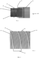
- FIG. 1 is a partial side view of a diopter adjustment 100 for a viewing optic showing the eyepiece 10 and scope tube 20.
- the eyepiece 10 and scope tube 20 are generally cylindrical with a central opening.
- the eyepiece 10 and scope tube 20 are coaxial.
- the eyepiece 10 has an internal surface having a first male thread 15.
- the scope tube 20 has an outer surface with a first female thread 30 which corresponds to the first male thread 15.
- the first male thread 15 engages the first female thread 30, resulting in the eye piece 10 being rotatable around and movable along the scope tube 20.
- the eyepiece 10 will move further onto the scope tube 20 further away from the rest of the viewing optic (not shown) depending on the direction of rotation.
- the first female thread 30 has single trapezoidal valley 36 spiraling around the scope tube 20.
- the first female thread 30 has a pitch 35 from 3.0 mm, or 3.25 mm, or 3.5 mm, or 3.75 mm, or 4.0 mm, or 4.25 mm, or 4.50 mm to 4.75 mm, or 5.0 mm, or 5.25 mm, or 5.5 mm, or 5.75 mm, or 6.0 mm.
- the first female thread 30 has a pitch 35 from 4.0 mm, or 4.25 mm, or 4.5 mm to 4.75 mm, or 5.0 mm.
- the first female thread 30 is trapezoidal, meaning the cross-sectional view of the thread has a generally trapezoidal shape.
- the thread angle A 1 is from 20°, or 25°, or 30° to 35°, or 40°, or 45°. In a further embodiment, the thread angle A 1 is from 25°, or 26°, or 27°, or 28°, or 29° to 30°, or 31°, or 32°, or 33°, or 34°, or 35°.
- a second female thread 40 is provided on the lands 38 of the first female thread 30.
- the pitch 35 of the first female thread 30 is greater than the pitch 45 of the second female thread 40.
- the pitch 35 of the first female thread 30 is from 2x, or 2.5x, or 3x, or 3.5x to 4x, or 4.5x, or 5x the pitch 45 of the second female thread 40.
- the pitch 35 of the first female thread 30 is from 2.5x, or 2.75x, or 3.0x, or 3.25x, or 3.5x, or 3.75x to 4.0x, or 4.25x, or 4.5x, or 4.75x, or 5.0x the pitch 45 of the second thread 40.
- the pitch 45 of the second female thread 40 is from .25 mm, or .5 mm, or .75 mm, or 1.0 mm to 1.25 mm, or 1.5 mm, or 1.75 mm, or 2.0 mm, or 2.25 mm, or 2.5 mm.
- the second female thread 40 has a pitch 45 from .3 mm, or .4 mm, or .5 mm, or .6 mm, or .7 mm to .8 mm, or .9 mm, or 1.0 mm, or 1.1. mm, or 1.2 mm, or 1.3 mm, or 1.4. mm, or 1.5 mm.
- the second female thread 40 is a standard V-thread profile consistent with ISO 261 and Unified Thread Standard.
- the thread angle A 2 is from 40°, or 45°, or 50°, or 55°, or 60° to 65°, or 70°, or 75°, or 80°.
- the thread angle A 2 is from 55°, or 56°, or 57°, or 58°, or 59° to 60°, or 61°, or 62°, or 63°, or 64°, or 65°.
- a jam nut 50 is a generally ring-shaped component having an inner surface having a second male thread (not shown) corresponding to the second female thread 40.
- the jam nut 50 is coaxial with the eyepiece 10 and the scope tube 20.
- the second male thread engages the second female thread 40 of the scope tube 20, resulting in the jam nut 50 being rotatable about and movable along the scope tube 20.
- the eyepiece 10 is first rotated (i.e., rotated either clockwise or counterclockwise depending on the desired adjustment) until the user determines the view is clear.
- the jam nut 50 is then rotated until it is snuggly secured against the eyepiece 10.
- the jam nut 50 acts as a lock.
- the fine pitch 45 of the second female thread 40 relative to the large pitch 35 of the first female thread 30 impedes the jam nut's 50 inadvertent movement when a viewing optic is moved, jostled or in use.
- the viewing optic is a scope for use with a firearm.
- the locking ability of the jam nut 50 prevents the eyepiece 10 from moving when the firearm is fired.
- the diopter adjustment mechanism may be used in association with any viewing optic, including but not limited to, a scope, a rifle scope, binoculars, camera, telescope, and similar viewing optics.
Landscapes
- Physics & Mathematics (AREA)
- Optics & Photonics (AREA)
- Engineering & Computer Science (AREA)
- General Engineering & Computer Science (AREA)
- General Physics & Mathematics (AREA)
- Astronomy & Astrophysics (AREA)
- Mechanical Engineering (AREA)
- Telescopes (AREA)
- Aiming, Guidance, Guns With A Light Source, Armor, Camouflage, And Targets (AREA)
- Transmission Devices (AREA)
- Lenses (AREA)
Description
- This application is a non-provisional application of and claims priority to
U.S. Provisional Patent Application No. 62/857,518 filed June 05, 2019 - The disclosure relates to an adjustment mechanism for a female threaded component. In one embodiment, the disclosure relates to an mechanism for a diopter adjustment.
- People's vision varies greatly from person to person. Even with a given individual, there can be a difference between the right eye's and left eye's vision. Diopter adjustments are provided on viewing optics, such as rifle scopes, cameras, etc., to allow the viewing optic to be focused for each user. In some instances when a viewing optic has two eye pieces, a diopter adjustment may be provided on one or both eyepieces to allow each individual eye piece to be adjusted to a user's specific eyes as well.
- There are two primary types of diopter adjustments. In a first type, the diopter adjustment has a fine thread pitch that allows a user to lock the position tight with a jam nut, but, because of the fine thread, it takes along time for the user to get to the setting they need. Because it takes so long, the user's eye can compensate while changing the focus. When looking through the viewing optic later, the user's eye is no long compensating and the diopter adjustment must be changed again.
- A second type of diopter adjustment is a fast focus diopter adjustment. A fast focus diopter adjustment uses a thread with a larger pitch. As a result, adjustments can be made quickly before a user's eye can compensate. Unfortunately, because of the large pitch, it is difficult to securely lock the diopter adjustment in place, and it will self-adjust when bumped or when the gun is fired.
- For the reasons discussed above, having a "zero stop" turret is a big advantage. Thus, there is a large need for a zero stop turret that can address these concerns.
-
US9939604B2 -
US2002/0176180A1 relates to an external helicoid thread comprising a helicoid thread composed of a first ridge whose both flanks are formed at a first flank angle, and a helicoid thread composed of second ridge whose both flanks are formed at a second flank angle, which is different from the first flank angle; and an internal helicoid thread is kept in screwed-state engagement with the external helicoid thread. In a lens barrel obtained using a connection based on such helicoid threads, the connection provided by these helicoid threads can thereby remain secured even if a sudden outside force is applied to the lens barrel. - In accordance with a first aspect of the present invention there is provided a viewing optic as defined in claim 1. Optional and/or preferable features are defined in the dependent claims.
- Embodiments of the disclosure are disclosed with reference to the accompanying drawings and are for illustrative purposes only. The disclosure is not limited in its application to the details of construction or the arrangement of the components illustrated in the drawings. The disclosure is capable of other embodiments or of being practiced or carried out in other various ways, so long as they fall within the scope of the appended claims. Like reference numerals are used to indicate like components. In the drawings:
-
FIG. 1 is a partial side view of a diopter adjustment mechanism used by embodiments of the present disclosure. -
FIG. 2 is a close-up of the first female thread and second female thread of a scope tube used by embodiments of the present disclosure. -
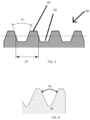
FIG. 3 is a schematic of a first female thread used by embodiments of the present disclosure. -
FIG. 4 is a schematic of a second female thread used by embodiments of the present disclosure. - Before explaining embodiments of the disclosure in detail, it is to be understood that the disclosure is not limited in its application to the details of construction and the arrangement of the components set forth in the following description or illustrated in the drawings. The technology of this present disclosure is capable of other embodiments or being practiced or carried out in various ways. Also, it is to be understood that the phraseology and terminology employed herein is for the purpose of description and should not be regarded as limiting.
- It will be appreciated by those skilled in the art that the set of features and/or capabilities may be readily adapted within the context of a standalone weapons sight, front-mount or rear-mount clip-on weapons sight, and other permutations of filed deployed optical weapons sights. Further, it will be appreciated by those skilled in the art that various combinations of features and capabilities may be incorporated into add-on modules for retrofitting existing fixed or variable weapons sights of any variety.
- It will be understood that when an element or layer is referred to as being "on", "connected to" or "coupled to" another element or layer, it can be directly on, connected or coupled to the other element or layer. Alternatively, intervening elements or layers may be present. In contrast, when an element is referred to as being "directly on," "directly connected to" or "directly coupled to" another element or layer, there are no intervening elements or layers present.
- Like numbers refer to like elements throughout. As used herein, the term "and/or" includes any and all combinations of one or more of the associated listed items.
- It will be understood that, although the terms first, second, etc. may be used herein to describe various elements, components, regions, and/or sections, these elements, components, regions, and/or sections should not be limited by these terms. These terms are only used to distinguish one element, component, region, or section from another element, component, region, or section. Thus, a first element, component, region, or section discussed below could be termed a second element, component, region, or section without departing from the disclosure.
- Spatially relative terms, such as "beneath," "below," "lower," "above," "upper," and the like, may be used herein for ease of description to describe one element or feature's relationship to another element(s) or feature(s) as illustrated in the figures. It will be understood that the spatially relative terms are intended to encompass different orientations of the device in use or operation in addition to the orientation depicted in the figures. For example, if the device in the figures is turned over, elements described as "below" or "beneath" other elements or features would then be oriented "above" the other elements or features. Thus, the exemplary term "below" can encompass both an orientation of above and below. The device may be otherwise oriented (rotated 90° or at other orientations) and the spatially relative descriptors used herein interpreted accordingly.
- The numerical ranges in this disclosure are approximate, and thus may include values outside of the range unless otherwise indicated. Numerical ranges include all values from and including the lower and the upper values, in increments of one unit, provided that there is a separation of at least two units between any lower value and any higher value. As an example, if a compositional, physical or other property, such as, for example, molecular weight, melt index, temperature etc., is from 100 to 1,000, it is intended that all individual values, such as 100, 101, 102, etc., and sub ranges, such as 100 to 144, 155 to 170, 197 to 200, etc., are expressly enumerated. For ranges containing values which are less than one or containing fractional numbers greater than one (e.g., 1.1, 1.5, etc.), one unit is considered to be 0.0001, 0.001, 0.01 or 0.1, as appropriate. For ranges containing single digit numbers less than ten (e.g., 1 to 5), one unit is typically considered to be 0.1. These are only examples of what is specifically intended, and all possible combinations of numerical values between the lowest value and the highest value enumerated, are to be considered to be expressly stated in this disclosure. Numerical ranges are provided within this disclosure for, among other things, relative amounts of components in a mixture, and various temperature and other parameter ranges recited in the description.
- As used herein, the term "viewing optic" refers to an apparatus used by a shooter or a spotter to select, identify or monitor a target. The "viewing optic" may rely on visual observation of the target, or, for example, on infrared (IR), ultraviolet (UV), radar, thermal, microwave, or magnetic imaging, radiation including X-ray, gamma ray, isotope and particle radiation, night vision, vibrational receptors including ultra-sound, sound pulse, sonar, seismic vibrations, magnetic resonance, gravitational receptors, broadcast frequencies including radio wave, television and cellular receptors, or other image of the target. The image of the target presented to the shooter by the "viewing optic" device may be unaltered, or it may be enhanced, for example, by magnification, amplification, subtraction, superimposition, filtration, stabilization, template matching, or other means. The target selected, identified or monitored by the "viewing optic" may be within the line of sight of the shooter, or tangential to the sight of the shooter, or the shooter's line of sight may be obstructed while the target acquisition device presents a focused image of the target to the shooter. The image of the target acquired by the "viewing optic" may be, for example, analog or digital, and shared, stored, archived, or transmitted within a network of one or more shooters and spotters by, for example, video, physical cable or wire, IR, radio wave, cellular connections, laser pulse, optical, 802.11b or other wireless transmission using, for example, protocols such as html, SML, SOAP, X.25, SNA, etc., Bluetooth™, Serial, USB or other suitable image distribution method. In one embodiment, the viewing optic is a riflescope. The term "viewing optic" is used interchangeably with "optic sight."
- As used herein, "pitch" refers to the distance between screw threads.
- As used herein, "land" refers to the portion between screw threads.
-
FIG. 1 is a partial side view of adiopter adjustment 100 for a viewing optic showing theeyepiece 10 andscope tube 20. Theeyepiece 10 andscope tube 20 are generally cylindrical with a central opening. Theeyepiece 10 andscope tube 20 are coaxial. Theeyepiece 10 has an internal surface having a firstmale thread 15. Thescope tube 20 has an outer surface with a firstfemale thread 30 which corresponds to the firstmale thread 15. The firstmale thread 15 engages the firstfemale thread 30, resulting in theeye piece 10 being rotatable around and movable along thescope tube 20. Theeyepiece 10 will move further onto thescope tube 20 further away from the rest of the viewing optic (not shown) depending on the direction of rotation. - As shown more clearly in
FIGS. 2 and3 , the firstfemale thread 30 has singletrapezoidal valley 36 spiraling around thescope tube 20. In an embodiment, the firstfemale thread 30 has apitch 35 from 3.0 mm, or 3.25 mm, or 3.5 mm, or 3.75 mm, or 4.0 mm, or 4.25 mm, or 4.50 mm to 4.75 mm, or 5.0 mm, or 5.25 mm, or 5.5 mm, or 5.75 mm, or 6.0 mm. In a further embodiment, the firstfemale thread 30 has apitch 35 from 4.0 mm, or 4.25 mm, or 4.5 mm to 4.75 mm, or 5.0 mm. - In an embodiment, the first
female thread 30 is trapezoidal, meaning the cross-sectional view of the thread has a generally trapezoidal shape. In an embodiment, the thread angle A1 is from 20°, or 25°, or 30° to 35°, or 40°, or 45°. In a further embodiment, the thread angle A1 is from 25°, or 26°, or 27°, or 28°, or 29° to 30°, or 31°, or 32°, or 33°, or 34°, or 35°. - Referring to
FIGS. 2 and4 , a secondfemale thread 40 is provided on thelands 38 of the firstfemale thread 30. As shown inFIGS. 1 and 2 , thepitch 35 of the firstfemale thread 30 is greater than thepitch 45 of the secondfemale thread 40. In an embodiment, thepitch 35 of the firstfemale thread 30 is from 2x, or 2.5x, or 3x, or 3.5x to 4x, or 4.5x, or 5x thepitch 45 of the secondfemale thread 40. In a further embodiment, thepitch 35 of the firstfemale thread 30 is from 2.5x, or 2.75x, or 3.0x, or 3.25x, or 3.5x, or 3.75x to 4.0x, or 4.25x, or 4.5x, or 4.75x, or 5.0x thepitch 45 of thesecond thread 40. - In an embodiment, the
pitch 45 of the secondfemale thread 40 is from .25 mm, or .5 mm, or .75 mm, or 1.0 mm to 1.25 mm, or 1.5 mm, or 1.75 mm, or 2.0 mm, or 2.25 mm, or 2.5 mm. In a further embodiment, the secondfemale thread 40 has apitch 45 from .3 mm, or .4 mm, or .5 mm, or .6 mm, or .7 mm to .8 mm, or .9 mm, or 1.0 mm, or 1.1. mm, or 1.2 mm, or 1.3 mm, or 1.4. mm, or 1.5 mm. - In an embodiment, the second
female thread 40 is a standard V-thread profile consistent with ISO 261 and Unified Thread Standard. The thread angle A2 is from 40°, or 45°, or 50°, or 55°, or 60° to 65°, or 70°, or 75°, or 80°. In a further embodiment the thread angle A2 is from 55°, or 56°, or 57°, or 58°, or 59° to 60°, or 61°, or 62°, or 63°, or 64°, or 65°. - Referring again to
FIG. 1 , ajam nut 50 is a generally ring-shaped component having an inner surface having a second male thread (not shown) corresponding to the secondfemale thread 40. Thejam nut 50 is coaxial with theeyepiece 10 and thescope tube 20. The second male thread engages the secondfemale thread 40 of thescope tube 20, resulting in thejam nut 50 being rotatable about and movable along thescope tube 20. - To adjust the focus of the
eyepiece 10, theeyepiece 10 is first rotated (i.e., rotated either clockwise or counterclockwise depending on the desired adjustment) until the user determines the view is clear. Thejam nut 50 is then rotated until it is snuggly secured against theeyepiece 10. Thejam nut 50 acts as a lock. Thefine pitch 45 of the secondfemale thread 40 relative to thelarge pitch 35 of the firstfemale thread 30 impedes the jam nut's 50 inadvertent movement when a viewing optic is moved, jostled or in use. For example, in an embodiment, the viewing optic is a scope for use with a firearm. The locking ability of thejam nut 50 prevents theeyepiece 10 from moving when the firearm is fired. - It will be appreciated that the diopter adjustment mechanism may be used in association with any viewing optic, including but not limited to, a scope, a rifle scope, binoculars, camera, telescope, and similar viewing optics.
- While multiple embodiments of the diopter adjustment mechanism features have been described in detail, it should be apparent that modifications and variations thereto are possible, all of which fall within the scope of the claims. With respect to the above description then, it is to be realized that the optimum dimensional relationships for the parts of the disclosed technology, to include variations in size, materials, shape, form, function and manner of operation, assembly and use, are deemed readily apparent and obvious to one skilled in the art. Further, since numerous modifications and changes will readily occur to those skilled in the art, it is not desired to limit the invention to the exact construction and operation shown and described, and accordingly, all suitable modifications may be resorted to, falling within the scope of the claims.
Claims (8)
- A viewing optic comprising:an eyepiece (10) having an inner surface having a first male thread (15);a scope tube (20) having an outer surface with a first female thread (30) and a second female thread (40), the first female thread (30) having a first pitch (35) forming a spiral thread and lands between the spiral threads, and the second female thread (40) having a second pitch (45) and disposed on the lands of the first female thread (30); and
a jam nut (50) rotationally secured to the outer surface of the scope tube (20) and having a second male thread on an inner surface,wherein the first pitch (35) is greater than the second pitch (45),wherein the first male thread (15) corresponds to and engages with the first female thread (30), andwherein the second male thread corresponds to and engages with the second female thread (40). - The viewing optic of claim 1, wherein the first female thread (30) is trapezoidal.
- The viewing optic of claim 1 or claim 2, wherein the second female thread (40) has a V-thread profile.
- The viewing optic of claim 1, claim 2 or claim 3, wherein the first pitch (35) is from 2.5x to 5x the second pitch, and/or wherein the first pitch (35) is from 3.0 mm to 6.0 mm.
- The viewing optic of claim 1 or of any of claims 2 to 4, wherein the second pitch (45) is from .25 mm to 2.5 mm.
- The viewing optic of claim 1 or of any of claims 2 to 5, wherein the thread angle of the first female thread (30) is from 20° to 45°.
- The viewing optic of claim 1 or of any of claims 2 to 6, wherein the thread angle of the second female thread (40) is from 40° to 80°.
- The viewing optic of claim 1 or of any of claims 2 to 7, wherein the viewing optic is selected from a scope, a rifle scope, binoculars, a camera, and a telescope, and/or wherein the viewing optic is adapted for use with a firearm.
Priority Applications (1)
| Application Number | Priority Date | Filing Date | Title |
|---|---|---|---|
| EP25151752.0A EP4517407A3 (en) | 2019-06-05 | 2020-06-05 | Diopter adjustment mechanism |
Applications Claiming Priority (2)
| Application Number | Priority Date | Filing Date | Title |
|---|---|---|---|
| US201962857518P | 2019-06-05 | 2019-06-05 | |
| PCT/US2020/036279 WO2021011110A2 (en) | 2019-06-05 | 2020-06-05 | Diopter adjustment mechanism |
Related Child Applications (1)
| Application Number | Title | Priority Date | Filing Date |
|---|---|---|---|
| EP25151752.0A Division EP4517407A3 (en) | 2019-06-05 | 2020-06-05 | Diopter adjustment mechanism |
Publications (3)
| Publication Number | Publication Date |
|---|---|
| EP3980833A2 EP3980833A2 (en) | 2022-04-13 |
| EP3980833A4 EP3980833A4 (en) | 2023-07-05 |
| EP3980833B1 true EP3980833B1 (en) | 2025-01-15 |
Family
ID=73650234
Family Applications (2)
| Application Number | Title | Priority Date | Filing Date |
|---|---|---|---|
| EP20840681.9A Active EP3980833B1 (en) | 2019-06-05 | 2020-06-05 | Diopter adjustment mechanism |
| EP25151752.0A Pending EP4517407A3 (en) | 2019-06-05 | 2020-06-05 | Diopter adjustment mechanism |
Family Applications After (1)
| Application Number | Title | Priority Date | Filing Date |
|---|---|---|---|
| EP25151752.0A Pending EP4517407A3 (en) | 2019-06-05 | 2020-06-05 | Diopter adjustment mechanism |
Country Status (9)
| Country | Link |
|---|---|
| US (3) | US11624393B2 (en) |
| EP (2) | EP3980833B1 (en) |
| JP (1) | JP7654569B2 (en) |
| KR (1) | KR102895108B1 (en) |
| CN (1) | CN114424107B (en) |
| AU (1) | AU2020315707B2 (en) |
| CA (1) | CA3142734A1 (en) |
| PH (1) | PH12021553048A1 (en) |
| WO (1) | WO2021011110A2 (en) |
Families Citing this family (5)
| Publication number | Priority date | Publication date | Assignee | Title |
|---|---|---|---|---|
| GB201900665D0 (en) * | 2019-01-17 | 2019-03-06 | Deben Group Industries Ltd | 06557607002 |
| KR102895108B1 (en) * | 2019-06-05 | 2025-12-03 | 쉘터드 윙스, 인크. 디/비/에이 보텍스 옵틱스 | Diopter adjustment mechanism |
| JP7260177B2 (en) * | 2020-05-14 | 2023-04-18 | 有限会社 ディオン光学技研 | Sighting scope diopter adjustment mechanism |
| US11493304B1 (en) * | 2021-04-23 | 2022-11-08 | Leupold & Stevens, Inc. | Diopter adjustment for optical device with overlapping left-handed and right-handed threads |
| EP4705818A1 (en) * | 2023-05-03 | 2026-03-11 | Sheltered Wings, Inc. D/b/a/ Vortex Optics | Diopter adjustment and locking mechanism using left and right threading on the same pitch diameter |
Family Cites Families (57)
| Publication number | Priority date | Publication date | Assignee | Title |
|---|---|---|---|---|
| FR1546220A (en) * | 1966-12-05 | 1968-11-15 | United Shoe Machinery Corp | self-locking threaded fastener |
| US3560080A (en) * | 1967-01-09 | 1971-02-02 | Ibm | Apparatus and method for adjustably mounting lenses |
| JPS4712934Y1 (en) * | 1968-08-28 | 1972-05-12 | ||
| US3888568A (en) * | 1974-06-20 | 1975-06-10 | Polaroid Corp | Multi-element lens assembly |
| DE2555953A1 (en) * | 1975-12-12 | 1977-06-16 | Schneider Co Optische Werke | SWITCHING DEVICE ON PHOTOGRAPHICAL AND KINEMATOGRAPHIC LENSES WITH CHANGEABLE FOCAL LENGTH |
| US4248496A (en) * | 1978-11-22 | 1981-02-03 | Bausch & Lomb Incorporated | Riflescope with data display in field of view |
| US4733945A (en) * | 1986-01-15 | 1988-03-29 | The Perkin-Elmer Corporation | Precision lens mounting |
| JPH0238248Y2 (en) * | 1986-06-30 | 1990-10-16 | ||
| JPH083571B2 (en) * | 1986-10-28 | 1996-01-17 | オリンパス光学工業株式会社 | Lens barrel |
| JPH0736334Y2 (en) * | 1988-11-01 | 1995-08-16 | オリンパス光学工業株式会社 | Lens barrel |
| US5121251A (en) * | 1989-04-25 | 1992-06-09 | Edwards Optical Corporation | Telemicroscope with absorbing annular baffle |
| US5076682A (en) * | 1989-06-29 | 1991-12-31 | Pasfield Michael T | Telemicroscopic apparatus on spectacles |
| US5245478A (en) * | 1992-05-06 | 1993-09-14 | New Focus, Inc. | Mount for Berek compensator |
| JPH0886306A (en) * | 1994-09-16 | 1996-04-02 | Kokubu:Kk | Lock screw |
| CN1267796A (en) * | 1999-03-23 | 2000-09-27 | 李青海 | Bolt with thread in both long and short pitches and its matched part |
| EP1150152A1 (en) | 2000-04-25 | 2001-10-31 | Hewlett-Packard Company, A Delaware Corporation | Optical assembly mounting |
| DE10026541A1 (en) * | 2000-05-27 | 2001-11-29 | Zeiss Carl | Device for the precise positioning of a component, in particular an optical component |
| US6461092B2 (en) * | 2001-02-22 | 2002-10-08 | Shao-Chien Tseng | Anti-dead locking, anti-vibration and loosening-proof bolt/nut structure |
| JP2002296476A (en) * | 2001-03-29 | 2002-10-09 | Olympus Optical Co Ltd | Lens frame |
| JP4974418B2 (en) * | 2001-05-23 | 2012-07-11 | オリンパス株式会社 | Lens barrel |
| JP2003279830A (en) * | 2002-03-25 | 2003-10-02 | Fuji Photo Optical Co Ltd | Lens device |
| AU2003270953B2 (en) * | 2002-12-18 | 2006-07-06 | Illinois Tool Works Inc. | Threaded fastener with dual reinforcing leads and improved substrate entry or lead end portion |
| JP4658740B2 (en) * | 2005-08-31 | 2011-03-23 | 明光産業株式会社 | Connecting member |
| KR100794794B1 (en) * | 2006-06-23 | 2008-01-15 | 삼성전자주식회사 | Focusing and projection optics of the optical projection device |
| JP2008173027A (en) * | 2007-01-16 | 2008-07-31 | Shimano Inc | Reel seat and spinning rod |
| US8033671B1 (en) * | 2007-08-10 | 2011-10-11 | Technology Solutions & Invention Llc | Retroreflective structures having a helical geometry |
| JP2010096210A (en) * | 2008-10-14 | 2010-04-30 | Miyoshi Miyamoto | Locknut |
| CN201344997Y (en) * | 2009-01-22 | 2009-11-11 | 重庆梧台科技发展有限公司 | Electric eyepiece with adjustable viewing field for optical microscope |
| CN101576109B (en) * | 2009-04-03 | 2011-11-16 | 孙中强 | Bolt combiner with double threads |
| CN201837777U (en) * | 2010-09-17 | 2011-05-18 | 李建成 | Telescope with ceramic structure |
| CN102590979B (en) * | 2012-01-17 | 2013-10-23 | 博立码杰通讯(深圳)有限公司 | Focal length adjusting device and optical imaging device |
| TWM454469U (en) * | 2012-09-10 | 2013-06-01 | Kwantex Res Inc | Concrete screw |
| CN102878179A (en) | 2012-09-23 | 2013-01-16 | 王超 | Double-thread bolt |
| WO2015066801A1 (en) | 2013-11-08 | 2015-05-14 | Institut National D'optique | Auto-centering of an optical element within a barrel |
| CN203822822U (en) * | 2014-05-07 | 2014-09-10 | 温州瑞强汽车部件有限公司 | Locknut |
| WO2016011544A1 (en) * | 2014-07-25 | 2016-01-28 | Institut National D'optique | Optical assemblies with tilt-controlled mounting of an optical element in a barrel |
| WO2016044927A1 (en) * | 2014-09-22 | 2016-03-31 | Institut National D'optique | Mounting of an optical element in a barrel using a flexible ring |
| CN204256239U (en) * | 2014-12-17 | 2015-04-08 | 孟繁有 | The sealed focusing laser amasthenic lens of a kind of long working distance |
| WO2016154755A1 (en) * | 2015-03-31 | 2016-10-06 | Institut National D'optique | Optical assembly with translatable centered sleeve |
| JP2016211649A (en) | 2015-05-08 | 2016-12-15 | 濱中ナット株式会社 | Sag preventive structure for bolt or nut, and bolt for the same |
| CN204646950U (en) * | 2015-05-22 | 2015-09-16 | 温州科腾紧固件有限公司 | Hexagonal flange band tooth backing-up screw |
| WO2016205346A1 (en) * | 2015-06-17 | 2016-12-22 | Sheltered Wings, Inc. D/B/A/ Vortex Optics | Dual focal plane reticles for optical sighting devices |
| DE102015114203B4 (en) * | 2015-08-26 | 2018-03-15 | Basler Ag | Camera body lens system and method for detecting and detecting the position of a lens |
| CN205176378U (en) * | 2015-11-11 | 2016-04-20 | 南通巨浪光电科技有限公司 | Gun sight eyepiece frame stop device |
| CN205720899U (en) * | 2016-06-29 | 2016-11-23 | 湖北久之洋红外系统股份有限公司 | A micro display device |
| US20180051737A1 (en) * | 2016-08-18 | 2018-02-22 | Research Engineering & Manufacturing Inc. | High performance thread rolling and thread locking fastener |
| CN106291902A (en) * | 2016-08-18 | 2017-01-04 | 河北汉光重工有限责任公司 | A kind of unification telescope round the clock with image co-registration function |
| CN108119508A (en) * | 2016-11-29 | 2018-06-05 | 刘义稳 | The locking combination nut of prefastening |
| TWM550406U (en) * | 2017-07-18 | 2017-10-11 | 尚茂智能科技股份有限公司 | Lens structure |
| CN206930815U (en) * | 2017-07-18 | 2018-01-26 | 尚茂智能科技股份有限公司 | Lens structure |
| CN207114850U (en) * | 2017-07-19 | 2018-03-16 | 南通云天光电科技有限公司 | A kind of eyepiece stalk for gun sight |
| CN207906264U (en) * | 2017-12-15 | 2018-09-25 | 明阳智慧能源集团股份公司 | A kind of Anti-loose locking nut of wind driven generation set main shaft bearing |
| CN207752221U (en) * | 2018-01-10 | 2018-08-21 | 河南金莱进出口有限公司 | A kind of screw thread object lens focusing monocular |
| JP7417616B2 (en) * | 2019-02-18 | 2024-01-18 | アンスティチュ・ナシオナル・ドプティーク | Centering optics using edge-contact mounting |
| KR102895108B1 (en) * | 2019-06-05 | 2025-12-03 | 쉘터드 윙스, 인크. 디/비/에이 보텍스 옵틱스 | Diopter adjustment mechanism |
| CN118310372A (en) * | 2020-01-15 | 2024-07-09 | 夏尔特银斯公司 | Zoom unit |
| US11579431B2 (en) * | 2020-01-15 | 2023-02-14 | Sheltered Wings, Inc. | Viewing optic with contours |
-
2020
- 2020-06-05 KR KR1020217040744A patent/KR102895108B1/en active Active
- 2020-06-05 JP JP2021572462A patent/JP7654569B2/en active Active
- 2020-06-05 EP EP20840681.9A patent/EP3980833B1/en active Active
- 2020-06-05 CN CN202080049001.9A patent/CN114424107B/en active Active
- 2020-06-05 PH PH1/2021/553048A patent/PH12021553048A1/en unknown
- 2020-06-05 EP EP25151752.0A patent/EP4517407A3/en active Pending
- 2020-06-05 US US16/893,688 patent/US11624393B2/en active Active
- 2020-06-05 WO PCT/US2020/036279 patent/WO2021011110A2/en not_active Ceased
- 2020-06-05 CA CA3142734A patent/CA3142734A1/en active Pending
- 2020-06-05 AU AU2020315707A patent/AU2020315707B2/en active Active
-
2023
- 2023-04-10 US US18/298,188 patent/US12209605B2/en active Active
-
2025
- 2025-01-27 US US19/038,019 patent/US20250172169A1/en active Pending
Also Published As
| Publication number | Publication date |
|---|---|
| US12209605B2 (en) | 2025-01-28 |
| WO2021011110A3 (en) | 2021-02-25 |
| EP3980833A4 (en) | 2023-07-05 |
| US11624393B2 (en) | 2023-04-11 |
| WO2021011110A2 (en) | 2021-01-21 |
| EP4517407A3 (en) | 2025-05-14 |
| PH12021553048A1 (en) | 2023-08-23 |
| CN114424107B (en) | 2024-11-01 |
| JP2022535900A (en) | 2022-08-10 |
| EP4517407A2 (en) | 2025-03-05 |
| AU2020315707B2 (en) | 2025-10-09 |
| CA3142734A1 (en) | 2021-01-21 |
| AU2020315707A1 (en) | 2022-01-06 |
| EP3980833A2 (en) | 2022-04-13 |
| CN114424107A (en) | 2022-04-29 |
| US20250172169A1 (en) | 2025-05-29 |
| KR20220016101A (en) | 2022-02-08 |
| US20230272814A1 (en) | 2023-08-31 |
| JP7654569B2 (en) | 2025-04-01 |
| US20200386259A1 (en) | 2020-12-10 |
| KR102895108B1 (en) | 2025-12-03 |
Similar Documents
| Publication | Publication Date | Title |
|---|---|---|
| US12209605B2 (en) | Diopter adjustment mechanism | |
| US20230384057A1 (en) | Zoom cell | |
| JP2024111249A (en) | Column and leg locking assembly for fixed platform | |
| US20230314101A1 (en) | Protective cover with alignment aperture | |
| US20230350174A1 (en) | Viewing Optic with Magnification Adjustment Ring | |
| US20240369823A1 (en) | Diopter adjustment and locking mechanism using left and right threading on the same pitch diameter | |
| JP2026516029A (en) | Diopter adjustment and locking mechanism using left and right threaded sections of the same effective diameter. | |
| CN122074119A (en) | The diopter adjustment and locking mechanism uses left and right threads with the same pitch diameter. | |
| AU2024267271A1 (en) | A viewing optic with digital image capture function |
Legal Events
| Date | Code | Title | Description |
|---|---|---|---|
| STAA | Information on the status of an ep patent application or granted ep patent |
Free format text: STATUS: THE INTERNATIONAL PUBLICATION HAS BEEN MADE |
|
| PUAI | Public reference made under article 153(3) epc to a published international application that has entered the european phase |
Free format text: ORIGINAL CODE: 0009012 |
|
| STAA | Information on the status of an ep patent application or granted ep patent |
Free format text: STATUS: REQUEST FOR EXAMINATION WAS MADE |
|
| 17P | Request for examination filed |
Effective date: 20220105 |
|
| AK | Designated contracting states |
Kind code of ref document: A2 Designated state(s): AL AT BE BG CH CY CZ DE DK EE ES FI FR GB GR HR HU IE IS IT LI LT LU LV MC MK MT NL NO PL PT RO RS SE SI SK SM TR |
|
| DAV | Request for validation of the european patent (deleted) | ||
| DAX | Request for extension of the european patent (deleted) | ||
| REG | Reference to a national code |
Ref country code: DE Ipc: F16B0033020000 Ref country code: DE Ref legal event code: R079 Ref document number: 602020044943 Country of ref document: DE Free format text: PREVIOUS MAIN CLASS: G02B0023000000 Ipc: F16B0033020000 |
|
| A4 | Supplementary search report drawn up and despatched |
Effective date: 20230602 |
|
| RIC1 | Information provided on ipc code assigned before grant |
Ipc: G02B 25/00 20060101ALN20230526BHEP Ipc: G02B 23/14 20060101ALN20230526BHEP Ipc: G02B 23/16 20060101ALI20230526BHEP Ipc: F41G 1/38 20060101ALI20230526BHEP Ipc: F16B 33/02 20060101AFI20230526BHEP |
|
| GRAP | Despatch of communication of intention to grant a patent |
Free format text: ORIGINAL CODE: EPIDOSNIGR1 |
|
| STAA | Information on the status of an ep patent application or granted ep patent |
Free format text: STATUS: GRANT OF PATENT IS INTENDED |
|
| RIC1 | Information provided on ipc code assigned before grant |
Ipc: G02B 25/00 20060101ALN20240729BHEP Ipc: G02B 23/14 20060101ALN20240729BHEP Ipc: G02B 23/16 20060101ALI20240729BHEP Ipc: F41G 1/38 20060101ALI20240729BHEP Ipc: F16B 33/02 20060101AFI20240729BHEP |
|
| INTG | Intention to grant announced |
Effective date: 20240807 |
|
| GRAS | Grant fee paid |
Free format text: ORIGINAL CODE: EPIDOSNIGR3 |
|
| GRAA | (expected) grant |
Free format text: ORIGINAL CODE: 0009210 |
|
| STAA | Information on the status of an ep patent application or granted ep patent |
Free format text: STATUS: THE PATENT HAS BEEN GRANTED |
|
| AK | Designated contracting states |
Kind code of ref document: B1 Designated state(s): AL AT BE BG CH CY CZ DE DK EE ES FI FR GB GR HR HU IE IS IT LI LT LU LV MC MK MT NL NO PL PT RO RS SE SI SK SM TR |
|
| REG | Reference to a national code |
Ref country code: CH Ref legal event code: EP Ref country code: GB Ref legal event code: FG4D |
|
| REG | Reference to a national code |
Ref country code: DE Ref legal event code: R096 Ref document number: 602020044943 Country of ref document: DE |
|
| REG | Reference to a national code |
Ref country code: IE Ref legal event code: FG4D |
|
| REG | Reference to a national code |
Ref country code: NL Ref legal event code: MP Effective date: 20250115 |
|
| PG25 | Lapsed in a contracting state [announced via postgrant information from national office to epo] |
Ref country code: NL Free format text: LAPSE BECAUSE OF FAILURE TO SUBMIT A TRANSLATION OF THE DESCRIPTION OR TO PAY THE FEE WITHIN THE PRESCRIBED TIME-LIMIT Effective date: 20250115 |
|
| PG25 | Lapsed in a contracting state [announced via postgrant information from national office to epo] |
Ref country code: RS Free format text: LAPSE BECAUSE OF FAILURE TO SUBMIT A TRANSLATION OF THE DESCRIPTION OR TO PAY THE FEE WITHIN THE PRESCRIBED TIME-LIMIT Effective date: 20250415 |
|
| PG25 | Lapsed in a contracting state [announced via postgrant information from national office to epo] |
Ref country code: FI Free format text: LAPSE BECAUSE OF FAILURE TO SUBMIT A TRANSLATION OF THE DESCRIPTION OR TO PAY THE FEE WITHIN THE PRESCRIBED TIME-LIMIT Effective date: 20250115 |
|
| PG25 | Lapsed in a contracting state [announced via postgrant information from national office to epo] |
Ref country code: PL Free format text: LAPSE BECAUSE OF FAILURE TO SUBMIT A TRANSLATION OF THE DESCRIPTION OR TO PAY THE FEE WITHIN THE PRESCRIBED TIME-LIMIT Effective date: 20250115 |
|
| PGFP | Annual fee paid to national office [announced via postgrant information from national office to epo] |
Ref country code: DE Payment date: 20250627 Year of fee payment: 6 |
|
| PG25 | Lapsed in a contracting state [announced via postgrant information from national office to epo] |
Ref country code: ES Free format text: LAPSE BECAUSE OF FAILURE TO SUBMIT A TRANSLATION OF THE DESCRIPTION OR TO PAY THE FEE WITHIN THE PRESCRIBED TIME-LIMIT Effective date: 20250115 |
|
| PGFP | Annual fee paid to national office [announced via postgrant information from national office to epo] |
Ref country code: GB Payment date: 20250627 Year of fee payment: 6 |
|
| REG | Reference to a national code |
Ref country code: LT Ref legal event code: MG9D |
|
| PG25 | Lapsed in a contracting state [announced via postgrant information from national office to epo] |
Ref country code: NO Free format text: LAPSE BECAUSE OF FAILURE TO SUBMIT A TRANSLATION OF THE DESCRIPTION OR TO PAY THE FEE WITHIN THE PRESCRIBED TIME-LIMIT Effective date: 20250415 Ref country code: IS Free format text: LAPSE BECAUSE OF FAILURE TO SUBMIT A TRANSLATION OF THE DESCRIPTION OR TO PAY THE FEE WITHIN THE PRESCRIBED TIME-LIMIT Effective date: 20250515 |
|
| PG25 | Lapsed in a contracting state [announced via postgrant information from national office to epo] |
Ref country code: HR Free format text: LAPSE BECAUSE OF FAILURE TO SUBMIT A TRANSLATION OF THE DESCRIPTION OR TO PAY THE FEE WITHIN THE PRESCRIBED TIME-LIMIT Effective date: 20250115 |
|
| PG25 | Lapsed in a contracting state [announced via postgrant information from national office to epo] |
Ref country code: LV Free format text: LAPSE BECAUSE OF FAILURE TO SUBMIT A TRANSLATION OF THE DESCRIPTION OR TO PAY THE FEE WITHIN THE PRESCRIBED TIME-LIMIT Effective date: 20250115 Ref country code: PT Free format text: LAPSE BECAUSE OF FAILURE TO SUBMIT A TRANSLATION OF THE DESCRIPTION OR TO PAY THE FEE WITHIN THE PRESCRIBED TIME-LIMIT Effective date: 20250515 |
|
| PGFP | Annual fee paid to national office [announced via postgrant information from national office to epo] |
Ref country code: FR Payment date: 20250625 Year of fee payment: 6 |
|
| PG25 | Lapsed in a contracting state [announced via postgrant information from national office to epo] |
Ref country code: GR Free format text: LAPSE BECAUSE OF FAILURE TO SUBMIT A TRANSLATION OF THE DESCRIPTION OR TO PAY THE FEE WITHIN THE PRESCRIBED TIME-LIMIT Effective date: 20250416 Ref country code: BG Free format text: LAPSE BECAUSE OF FAILURE TO SUBMIT A TRANSLATION OF THE DESCRIPTION OR TO PAY THE FEE WITHIN THE PRESCRIBED TIME-LIMIT Effective date: 20250115 |
|
| PGFP | Annual fee paid to national office [announced via postgrant information from national office to epo] |
Ref country code: AT Payment date: 20250620 Year of fee payment: 6 |
|
| PG25 | Lapsed in a contracting state [announced via postgrant information from national office to epo] |
Ref country code: SE Free format text: LAPSE BECAUSE OF FAILURE TO SUBMIT A TRANSLATION OF THE DESCRIPTION OR TO PAY THE FEE WITHIN THE PRESCRIBED TIME-LIMIT Effective date: 20250115 |
|
| PG25 | Lapsed in a contracting state [announced via postgrant information from national office to epo] |
Ref country code: SM Free format text: LAPSE BECAUSE OF FAILURE TO SUBMIT A TRANSLATION OF THE DESCRIPTION OR TO PAY THE FEE WITHIN THE PRESCRIBED TIME-LIMIT Effective date: 20250115 |
|
| PG25 | Lapsed in a contracting state [announced via postgrant information from national office to epo] |
Ref country code: DK Free format text: LAPSE BECAUSE OF FAILURE TO SUBMIT A TRANSLATION OF THE DESCRIPTION OR TO PAY THE FEE WITHIN THE PRESCRIBED TIME-LIMIT Effective date: 20250115 |
|
| PG25 | Lapsed in a contracting state [announced via postgrant information from national office to epo] |
Ref country code: IT Free format text: LAPSE BECAUSE OF FAILURE TO SUBMIT A TRANSLATION OF THE DESCRIPTION OR TO PAY THE FEE WITHIN THE PRESCRIBED TIME-LIMIT Effective date: 20250115 |
|
| REG | Reference to a national code |
Ref country code: DE Ref legal event code: R097 Ref document number: 602020044943 Country of ref document: DE |
|
| PG25 | Lapsed in a contracting state [announced via postgrant information from national office to epo] |
Ref country code: CZ Free format text: LAPSE BECAUSE OF FAILURE TO SUBMIT A TRANSLATION OF THE DESCRIPTION OR TO PAY THE FEE WITHIN THE PRESCRIBED TIME-LIMIT Effective date: 20250115 Ref country code: EE Free format text: LAPSE BECAUSE OF FAILURE TO SUBMIT A TRANSLATION OF THE DESCRIPTION OR TO PAY THE FEE WITHIN THE PRESCRIBED TIME-LIMIT Effective date: 20250115 |
|
| PGFP | Annual fee paid to national office [announced via postgrant information from national office to epo] |
Ref country code: RO Payment date: 20250701 Year of fee payment: 6 |
|
| PG25 | Lapsed in a contracting state [announced via postgrant information from national office to epo] |
Ref country code: SK Free format text: LAPSE BECAUSE OF FAILURE TO SUBMIT A TRANSLATION OF THE DESCRIPTION OR TO PAY THE FEE WITHIN THE PRESCRIBED TIME-LIMIT Effective date: 20250115 |
|
| PLBE | No opposition filed within time limit |
Free format text: ORIGINAL CODE: 0009261 |
|
| STAA | Information on the status of an ep patent application or granted ep patent |
Free format text: STATUS: NO OPPOSITION FILED WITHIN TIME LIMIT |
|
| REG | Reference to a national code |
Ref country code: CH Ref legal event code: L10 Free format text: ST27 STATUS EVENT CODE: U-0-0-L10-L00 (AS PROVIDED BY THE NATIONAL OFFICE) Effective date: 20251126 |
|
| 26N | No opposition filed |
Effective date: 20251016 |
|
| REG | Reference to a national code |
Ref country code: CH Ref legal event code: H13 Free format text: ST27 STATUS EVENT CODE: U-0-0-H10-H13 (AS PROVIDED BY THE NATIONAL OFFICE) Effective date: 20260127 |
|
| PG25 | Lapsed in a contracting state [announced via postgrant information from national office to epo] |
Ref country code: MC Free format text: LAPSE BECAUSE OF FAILURE TO SUBMIT A TRANSLATION OF THE DESCRIPTION OR TO PAY THE FEE WITHIN THE PRESCRIBED TIME-LIMIT Effective date: 20250115 |
|
| PG25 | Lapsed in a contracting state [announced via postgrant information from national office to epo] |
Ref country code: LU Free format text: LAPSE BECAUSE OF NON-PAYMENT OF DUE FEES Effective date: 20250605 |
|
| REG | Reference to a national code |
Ref country code: BE Ref legal event code: MM Effective date: 20250630 |
|
| REG | Reference to a national code |
Ref country code: AT Ref legal event code: UEP Ref document number: 1760009 Country of ref document: AT Kind code of ref document: T Effective date: 20250115 |
|
| PG25 | Lapsed in a contracting state [announced via postgrant information from national office to epo] |
Ref country code: IE Free format text: LAPSE BECAUSE OF NON-PAYMENT OF DUE FEES Effective date: 20250605 |
|
| PG25 | Lapsed in a contracting state [announced via postgrant information from national office to epo] |
Ref country code: BE Free format text: LAPSE BECAUSE OF NON-PAYMENT OF DUE FEES Effective date: 20250630 |
|
| PG25 | Lapsed in a contracting state [announced via postgrant information from national office to epo] |
Ref country code: CH Free format text: LAPSE BECAUSE OF NON-PAYMENT OF DUE FEES Effective date: 20250630 |