EP3980232B1 - Method of forming a cut in a polymeric component - Google Patents
Method of forming a cut in a polymeric component Download PDFInfo
- Publication number
- EP3980232B1 EP3980232B1 EP20746469.4A EP20746469A EP3980232B1 EP 3980232 B1 EP3980232 B1 EP 3980232B1 EP 20746469 A EP20746469 A EP 20746469A EP 3980232 B1 EP3980232 B1 EP 3980232B1
- Authority
- EP
- European Patent Office
- Prior art keywords
- polymeric
- blade
- mandrel
- closure
- polymeric component
- Prior art date
- Legal status (The legal status is an assumption and is not a legal conclusion. Google has not performed a legal analysis and makes no representation as to the accuracy of the status listed.)
- Active
Links
Images
Classifications
-
- B—PERFORMING OPERATIONS; TRANSPORTING
- B29—WORKING OF PLASTICS; WORKING OF SUBSTANCES IN A PLASTIC STATE IN GENERAL
- B29D—PRODUCING PARTICULAR ARTICLES FROM PLASTICS OR FROM SUBSTANCES IN A PLASTIC STATE
- B29D99/00—Subject matter not provided for in other groups of this subclass
- B29D99/0096—Producing closure members for containers, e.g. closure caps or stoppers
-
- B—PERFORMING OPERATIONS; TRANSPORTING
- B26—HAND CUTTING TOOLS; CUTTING; SEVERING
- B26D—CUTTING; DETAILS COMMON TO MACHINES FOR PERFORATING, PUNCHING, CUTTING-OUT, STAMPING-OUT OR SEVERING
- B26D3/00—Cutting work characterised by the nature of the cut made; Apparatus therefor
- B26D3/16—Cutting rods or tubes transversely
- B26D3/164—Cutting rods or tubes transversely characterised by means for supporting the tube from the inside
-
- B—PERFORMING OPERATIONS; TRANSPORTING
- B29—WORKING OF PLASTICS; WORKING OF SUBSTANCES IN A PLASTIC STATE IN GENERAL
- B29C—SHAPING OR JOINING OF PLASTICS; SHAPING OF MATERIAL IN A PLASTIC STATE, NOT OTHERWISE PROVIDED FOR; AFTER-TREATMENT OF THE SHAPED PRODUCTS, e.g. REPAIRING
- B29C69/00—Combinations of shaping techniques not provided for in a single one of main groups B29C39/00 - B29C67/00, e.g. associations of moulding and joining techniques; Apparatus therefore
- B29C69/001—Combinations of shaping techniques not provided for in a single one of main groups B29C39/00 - B29C67/00, e.g. associations of moulding and joining techniques; Apparatus therefore a shaping technique combined with cutting, e.g. in parts or slices combined with rearranging and joining the cut parts
-
- B—PERFORMING OPERATIONS; TRANSPORTING
- B65—CONVEYING; PACKING; STORING; HANDLING THIN OR FILAMENTARY MATERIAL
- B65D—CONTAINERS FOR STORAGE OR TRANSPORT OF ARTICLES OR MATERIALS, e.g. BAGS, BARRELS, BOTTLES, BOXES, CANS, CARTONS, CRATES, DRUMS, JARS, TANKS, HOPPERS, FORWARDING CONTAINERS; ACCESSORIES, CLOSURES, OR FITTINGS THEREFOR; PACKAGING ELEMENTS; PACKAGES
- B65D41/00—Caps, e.g. crown caps or crown seals, i.e. members having parts arranged for engagement with the external periphery of a neck or wall defining a pouring opening or discharge aperture; Protective cap-like covers for closure members, e.g. decorative covers of metal foil or paper
- B65D41/32—Caps or cap-like covers with lines of weakness, tearing-strips, tags, or like opening or removal devices, e.g. to facilitate formation of pouring openings
- B65D41/34—Threaded or like caps or cap-like covers provided with tamper elements formed in, or attached to, the closure skirt
- B65D41/3423—Threaded or like caps or cap-like covers provided with tamper elements formed in, or attached to, the closure skirt with flexible tabs, or elements rotated from a non-engaging to an engaging position, formed on the tamper element or in the closure skirt
- B65D41/3428—Threaded or like caps or cap-like covers provided with tamper elements formed in, or attached to, the closure skirt with flexible tabs, or elements rotated from a non-engaging to an engaging position, formed on the tamper element or in the closure skirt the tamper element being integrally connected to the closure by means of bridges
-
- B—PERFORMING OPERATIONS; TRANSPORTING
- B26—HAND CUTTING TOOLS; CUTTING; SEVERING
- B26D—CUTTING; DETAILS COMMON TO MACHINES FOR PERFORATING, PUNCHING, CUTTING-OUT, STAMPING-OUT OR SEVERING
- B26D1/00—Cutting through work characterised by the nature or movement of the cutting member or particular materials not otherwise provided for; Apparatus or machines therefor; Cutting members therefor
- B26D1/0006—Cutting members therefor
- B26D2001/002—Materials or surface treatments therefor, e.g. composite materials
-
- B—PERFORMING OPERATIONS; TRANSPORTING
- B26—HAND CUTTING TOOLS; CUTTING; SEVERING
- B26F—PERFORATING; PUNCHING; CUTTING-OUT; STAMPING-OUT; SEVERING BY MEANS OTHER THAN CUTTING
- B26F2210/00—Perforating, punching, cutting-out, stamping-out, severing by means other than cutting of specific products
- B26F2210/04—Making plastic pilferproof screw caps by cutting a tamper ring
Definitions
- the present invention relates generally to a method of forming a cut (e.g., a slit) in a polymeric component. More specifically, the present invention relates to a method of forming a cut in a polymeric component such as a polymeric closure using a mandrel.
- Polymeric components have been used in many applications over the years. Some polymeric components need to have cuts (e.g., slits) formed therein.
- a polymeric closure is a polymeric closure.
- Polymeric closures often include a tamper-evident feature to indicate to a user that the closure may have been opened. Tamper-evident features may include frangible connections. These frangible connections are typically formed by a cutting process using one or more blades and a mandrel with gaps or spaces formed therein to receive the one or more blades.
- the blade is typically a single continuous blade or a single continuous blade containing notched interruptions.
- the mandrel uses a narrow gap formed therein to receive the blade during the cutting process.
- the upper and lower bounds of the gap in the mandrel assist in preventing or inhibiting wall deflection greater than the blade overlap distance. This can achieve stable results using thinner blades when the gap in the mandrel and the blade overlap into the gap are appropriately dimensioned.
- WO 95/24299 A1 discloses a method and apparatus for vertically scoring a tamper-indicating plastic closure includes a rotatably-driven carousel which includes mandrel assemblies at the periphery thereof.
- Each mandrel assembly includes a rotatable mandrel on which a respectively closure is positioned in operative association, so that the mandrel and closure are moved relative to an associated scoring mechanism.
- the scoring mechanism includes a rotatably driven scoring blade arranged to engage and cut the pilfer band of a respective closure.
- the invention relates to a method according to claim 1.
- the invention relates to a method according to claim 10.
- a method of forming a cut in a polymeric component includes providing a mandrel and a blade assembly including at least one blade.
- the mandrel includes a rigid portion and a conformal support ring.
- the conformal support ring comprises a material being softer than the material forming the at least one blade.
- a polymeric component is also provided.
- the polymeric component may be a polymeric closure according to one method. It is contemplated that the polymeric component may be other items such as a polymeric sheet, polymeric block or other polymeric objects.
- the polymeric component is positioned between the mandrel and the at least one blade.
- the mandrel is moved towards the blade assembly.
- the blade assembly is moved towards the mandrel.
- the mandrel and the blade assembly are moved towards each other.
- the polymeric component is cut via the at least one blade.
- the at least one blade is configured and positioned to extend into the conformal support ring after the at least one blade has penetrated through the polymeric component.
- the methods of the present application are desirable in their ability to cut paths in multiple horizontal directions.
- the cut may be in the form a slit.
- the methods of the present application are especially desirable in their ability to cut paths in at least one horizontal direction and at least one vertical direction.
- the cuts may be a diagonal cut or a spiral cut.
- These cuts may be in the form of frangible connections in one embodiment.
- Some frangible connections include scoring or scored lines, notches, leaders, nicks or line of weaknesses. It is contemplated that the cuts do not form frangible connections in another embodiment. For example, there may be multiple cuts formed by the methods without any frangible connections.
- the methods of the present application overcome the problems associated with providing support to the wall of the polymeric component, while achieving full depth cut penetration, while cutting over a wide area using multiple blades.
- the methods of the present application for cutting polymeric components provide an efficient, cost-effective solution.
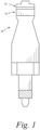
- a mandrel 10 is shown according to one embodiment.
- the mandrel functions to provide support to a polymeric component during the cutting process. More specifically, the mandrel assists in (1) bracing a wall of the polymeric component (e.g., a sidewall or a skirt portion of a closure) and (2) preventing or inhibiting the wall from deflecting out of the blade path during the cutting process. Ultimately, the mandrel assists in producing a properly sized, shaped and located cut(s) in the polymeric component in conjunction with the blade assembly.
- the general exterior shape of the mandrel generally corresponds with the shape of the polymeric component. It is contemplated that the shape and size of the mandrel may be different than that shown in FIG. 1 .
- the mandrel 10 includes a rigid portion 12 and a conformal support ring 14.
- the rigid portion 12 of the mandrel 10 is typically metal.
- Non-limiting examples of metallic materials that may be used in forming the mandrel include aluminum, steel or the combination thereof. It is contemplated that other metallic materials may be used in forming the mandrel. It is contemplated that the mandrel may be non-metallic.
- One contemplated non-metallic material that may be used to form the mandrel is a fiber-filled polymeric material.
- the conformal support ring 14 is sized and shaped to receive the at least one blade.
- the conformal support ring is designed to support an inner wall of the polymeric component to assist in preventing or inhibiting the wall from deflecting out of the blade path during the cutting process. By reducing or eliminating the any deflection, a full depth, repeatable cut can be more consistently obtained in the polymeric component.
- the mandrel, including the conformal support ring has the ability to support the inner wall of the polymeric component to achieve full depth, repeatable cuts over a wide area with a plurality of blades.
- the blade(s) are typically in a horizontal orientation and/or a vertical orientation. It is contemplated that the blades may be in other orientations such as diagonal or spiral orientations.
- the conformal support ring may be formed or processed by different methods in the mandrel.
- the conformal support ring may be cast in place or snapped into an opening or grove formed in the mandrel.
- the conformal support ring 14 comprises a material being softer than the material forming the blade(s). It is desirable for the conformal support ring material to be formed from a non-metallic material.
- One especially desirable material for forming the conformal support ring is a polymeric material.
- polymeric materials that may be used in forming the conformal support ring are urethanes (e.g., polyurethanes such as a thermoplastic polyurethane (TPU)), elastomers (e.g., thermoplastic elastomers), plastomers, rubber or rubber-like material (e.g., natural rubber, silicone rubber, neoprene rubber, nitrile rubber, butyl rubber, synthetic rubber) or combinations thereof.
- TPU thermoplastic polyurethane
- elastomers e.g., thermoplastic elastomers
- plastomers plastomers
- rubber or rubber-like material e.g., natural rubber, silicone rubber, neopren
- One non-limiting commercial example for forming a conformal support ring is Prodways' TPU-70A thermoplastic urethane.
- Another non-limiting commercial example for forming a conformal support ring is Hei-Cast's 8400 and 8400N multi-component polyurethane system that can be obtained through ICOMold. It is contemplated that other polymeric materials may be used in forming the conformal support ring.
- non-polymeric materials may be used in forming the conformal support ring.
- Non-limiting examples of the same include softer metals (e.g., copper), and wood.
- the conformal support ring is sized with respect to the blade(s).
- the sizes of the conformal support ring can be wide ranging and are dependent on the blade and the material properties of the conformal support ring.
- a conformal support ring may be configured with a thermoplastic polyurethane (TPU) material of 70-A shore durometer having a thickness of about 1 mm with a 0.35 mm of blade overlap into the conformal support ring.
- TPU thermoplastic polyurethane
- a 50-A shore durometer TPU material having a ring thickness of 2 mm is used with a blade overlap of 0.15 mm.
- the conformal support ring may be configured with materials with a hardness range from about 40 shore A to about 75 shore D.
- materials for forming a conformal support ring are cast urethanes.
- the material forming the conformal support ring is generally flexible and tough. These material properties of the conformal support ring may be shown in various tests such as the hardness test, toughness test, and elongation at break XY (average of XY).
- the material forming the conformal support ring generally has a hardness test as measured by Shore A of from about 30 to about 100 and, more specifically, from about 50 to about 90 and, even more specifically, from about 60 to about 80.
- the material forming the conformal support ring generally has an elongation at break XY (average XY) as measured by ISO 527 of at least about 200% and, more specifically, at least about 350%.
- the material forming the conformal support ring generally has an elongation of break XY (average XY) as measured by ISO 527 of from about 250 to about 500%, and, more specifically, from about 300 to about 400%.
- the material forming the conformal support ring generally has a low compressibility and a desirable cut resistance.
- the compressibility of the conformal support ring as measured by ASTM D575-91 is generally from about 5% to about 50% and, more specifically, from about 10% to about 40%, and even more specifically from about 10% to about 30%.
- a blade assembly includes at least one blade.
- the at least one blade assists in forming one or more cuts in the polymeric component.
- the cuts may be in the form of frangible connections. Some frangible connections include scoring or scored lines, notches, leaders, nicks or line of weaknesses.
- the cuts may be made without any frangible connections.
- the blade may be a single continuous blade or a plurality of multiple individual blades.
- a single continuous blade may be used with notched interruptions that act effectively as multiple blades.
- the blades are designed to provide full depth, repeatable cut penetration into the polymeric component.
- the at least one blade includes a horizontal blade configured to cut the polymeric component in a general horizontal direction.
- the at least one blade includes a plurality of horizontal blades configured to cut the polymeric component in multiple general horizontal directions.
- the at least one blade also may be a vertical blade or a plurality of vertical blades that are configured to cut the polymeric component in a generally vertical direction.
- the least one blade may be a combination of one or more horizontal blades and one or more vertical blades. It is contemplated that the cuts may be formed in directions other than being generally in a horizontal or generally vertical direction. For example, other directions, for example, can be diagonal or spiral.
- the thickness of the blades varies depending on the desired cuts to be formed.
- the blades typically have a thickness of from about 0.5 mm to about 2 mm and, more specifically, from about 0.5 mm to about 1.2 mm.
- the blades are typically made of a hardened material.
- a material forming the blade(s) is a hardened tool steel with hardness from 57 to 62 HRC such as A2. It is contemplated that other materials may be used in forming the blades.
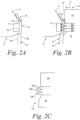
- a blade assembly is typically moved with respect to the mandrel. This is shown in FIGS. 2A, 2B where a blade assembly 30 is moved with respect to a mandrel 10 in the direction of arrow A. It is contemplated that the mandrel may be moved with respect to the blade assembly in another method. In this method, the mandrel would move in an opposite direction to arrow A. It is also contemplated that the mandrel and the blade assembly may be moved with respect to each other.
- FIG. 2A is a cross-sectional view before the blades have penetrated the polymeric closure
- FIG. 2B is a cross-sectional view after the blades have penetrated the polymeric closure.
- FIG. 2A shows the mandrel 10 including the rigid portion 12 and the conformal support ring 14, and the polymeric closure 20.
- the polymeric closure 20 is shown abutting the mandrel 10.
- the polymeric closure 20 is a polymeric closure that includes an inner surface 20a and an outer surface 20b.
- the inner surface 20a of the polymeric closure 20 abuts exterior surfaces 12a, 14a of the mandrel 10.
- the mandrel supports the polymeric closure during the cutting.
- the polymeric closure 20 includes a top wall portion (not shown in FIG. 2A ), an annular polymeric skirt 24 and a tamper-evident band 26.
- FIG. 2B the mandrel 10, the polymeric closure 20 and the blade assembly 30 are shown during the cutting process. More specifically, FIG. 2B shows the mandrel 10, the polymeric closure 20 and the blade assembly 30 after the blades have penetrated the polymeric closure 20. The blade assembly 30 of FIG. 2B has moved in the direction of arrow A towards the mandrel 10.
- the blade assembly 30 includes a first supporting section 32, a second supporting section 34, and three horizontal blades 36a-c.
- the horizontal blades 36a-c cut in a generally horizontal direction.
- the three horizontal blades 36a-c are shown as being connected to each other in FIG. 2B .
- the first supporting section 32 supports the annular polymeric skirt 24 of the polymeric closure 20 and the second supporting section 34 supports the tamper-evident band 26 of the polymeric closure 20.
- the supporting sections 32, 34 of the blade assembly 30 work in combination with the mandrel 10 in supporting the walls of the polymeric closure 20.
- the blades may be a single continuous blade with two notched interruptions that form three individual points. This is shown, for example, in FIG. 2C with blade assembly 130 that includes a first supporting section 132, a second supporting section 134 and a plurality of individual blade points 136a-c. Such an embodiment would function in a similar manner as the three individual blades 36a-c of FIG. 2B .
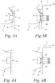
- FIGS. 3A, 3B disclose the mandrel 10, the polymeric closure 20 and a blade assembly 230.
- the blade assembly 230 includes a first supporting section 232, a second supporting section 234, and a plurality of individual blades 236a, 236b and 238. Blades 236a, 236b cut in the generally horizontal direction, while blade 238 cuts in the generally vertical direction.
- FIGS. 4A, 4B disclose a mandrel 310, a polymeric component 350 and the blade assembly 230.
- the polymeric component is a generally straight component. It is contemplated that the polymeric component may be sized or shaped differently.
- the shape of the mandrel corresponds to the shape of the polymeric component.
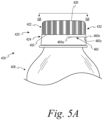
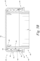
- FIGS. 5A , 5B illustrate a package 400 that includes a container 408 and a polymeric closure 420.
- FIG. 5A depicts the closure 420 and the container 408 in an unopened position.
- the polymeric closure 420 is one non-limiting example of a polymeric component that may be formed using the methods of the present invention.
- the closures are configured to be placed on a container or bottle that contain product.
- the product is typically a liquid product, but also may be a solid product or a combination of a liquid and solid product.
- the polymeric closure 420 is a one-piece closure assembly. It is contemplated that a two-piece closure assembly may be formed using the methods of the present invention.
- the polymeric closure 420 is generally cylindrically shaped.
- the polymeric closure 420 includes a first closure portion or lid 422 and a second closure portion or base 424.
- the first closure portion 422 includes a polymeric top wall portion 426 and a polymeric annular skirt portion 432.
- the second closure portion 424 includes a polymeric tamper-evident band 440.
- the polymeric tamper-evident band 440 depends from and is partially detachably connected to the polymeric annular skirt portion 432 by a first frangible connection 450.
- the first closure portion 422 further includes a polymeric continuous plug seal 428 and an outer seal 430.
- the polymeric annular skirt portion 432 includes an internal thread formation 434 for mating engagement with an external thread formation of a container.
- the internal thread formation 434 includes a first closure lead 436 and a second closure lead 438.
- the first and second closure leads may be continuous or discontinuous.
- the internal thread formation of the closure may be a helical thread formation or other thread formations.
- the polymeric closure 420 of FIG. 5A includes the first frangible connection 450 and a second frangible connection 460.
- the frangible connection 450 is in a generally horizontal direction, while the second frangible connection 460 has horizontal portions 460a, 460c and a vertical direction portion 460b.
- the closure 420 is made of polymeric material and is typically made of an olefin (e.g., polyethylene (PE), polypropylene (PP)), polyethylene terephthalate (PET) or blends thereof.
- PE polyethylene
- PP polypropylene
- PET polyethylene terephthalate
- the closures are typically formed by processes such as injection or compression molding, extrusion or the combination thereof.
Landscapes
- Engineering & Computer Science (AREA)
- Mechanical Engineering (AREA)
- Life Sciences & Earth Sciences (AREA)
- Forests & Forestry (AREA)
- Closures For Containers (AREA)
- Details Of Cutting Devices (AREA)
- Nonmetal Cutting Devices (AREA)
- Perforating, Stamping-Out Or Severing By Means Other Than Cutting (AREA)
- Shaping Of Tube Ends By Bending Or Straightening (AREA)
Description
- The present invention relates generally to a method of forming a cut (e.g., a slit) in a polymeric component. More specifically, the present invention relates to a method of forming a cut in a polymeric component such as a polymeric closure using a mandrel.
- Polymeric components have been used in many applications over the years. Some polymeric components need to have cuts (e.g., slits) formed therein. One non-limiting example of such a polymeric component is a polymeric closure. Polymeric closures often include a tamper-evident feature to indicate to a user that the closure may have been opened. Tamper-evident features may include frangible connections. These frangible connections are typically formed by a cutting process using one or more blades and a mandrel with gaps or spaces formed therein to receive the one or more blades. The blade is typically a single continuous blade or a single continuous blade containing notched interruptions. The mandrel uses a narrow gap formed therein to receive the blade during the cutting process. The upper and lower bounds of the gap in the mandrel assist in preventing or inhibiting wall deflection greater than the blade overlap distance. This can achieve stable results using thinner blades when the gap in the mandrel and the blade overlap into the gap are appropriately dimensioned.
- International patent application
WO 95/24299 A1 - A problem arises with this method when thicker blades (e.g., 1.0 mm) are needed to be stacked or inverted to achieve a multi-level cutting geometry. Under these situations, this method becomes very difficult and unpractical. This method is also more difficult when a vertical cut is needed because this requires reliable timing such that the vertical blade is aligned with the gap in the mandrel.
- It would be desirable to provide efficient methods of forming a cut in a polymeric component that is adaptable under different cutting requirements.
- According to one aspect the invention relates to a method according to claim 1.
- According to another aspect, the invention relates to a method according to
claim 10. - The above summary is not intended to represent each embodiment or every aspect of the present invention. Additional features and benefits of the present invention are apparent from the detailed description and figures set forth below.
- Other advantages of the invention will become apparent upon reading the following detailed description and upon reference to the drawings in which:
-
FIG. 1 is a front view of a mandrel that is used in one method of the present application. -
FIG. 2A is a side cross-sectional view of a mandrel and a polymeric closure used in one method before the blade penetration. -
FIG. 2B is a side cross-sectional view of the mandrel and the polymeric closure ofFIG. 2A after the blade penetration. -
FIG. 2C is a side cross-sectional view of a blade assembly according to one embodiment. -
FIG. 3A is a side cross-sectional view of a mandrel and a polymeric closure used in one method before the blade penetration. -
FIG. 3B is a side cross-sectional view of the mandrel and the polymeric closure ofFIG. 3A after the blade penetration. -
FIG. 4A is a side cross-sectional view of a mandrel and a polymeric component used in one method before the blade penetration. -
FIG. 4B is a side cross-sectional view of the mandrel and the polymeric component ofFIG. 4A after the blade penetration. -
FIG. 5A is a side view of a package including a closure and a container. -
FIG. 5B is a cross-sectional view taken generally alongline 5B-5B inFIG. 5A . - While the invention is susceptible to various modifications and alternative forms, specific embodiments thereof have been shown by way of example in the drawings and will herein be described in detail. It should be understood, however, that it is not intended to limit the invention to the particular forms disclosed, but on the contrary, the intention is to cover all modifications, equivalents, and alternatives falling within the scope of the invention as defined by the appended claims.
- A method of forming a cut in a polymeric component includes providing a mandrel and a blade assembly including at least one blade. The mandrel includes a rigid portion and a conformal support ring. The conformal support ring comprises a material being softer than the material forming the at least one blade. A polymeric component is also provided. The polymeric component may be a polymeric closure according to one method. It is contemplated that the polymeric component may be other items such as a polymeric sheet, polymeric block or other polymeric objects.
- The polymeric component is positioned between the mandrel and the at least one blade. In one method, the mandrel is moved towards the blade assembly. In another method, the blade assembly is moved towards the mandrel. In a further method, the mandrel and the blade assembly are moved towards each other. The polymeric component is cut via the at least one blade. The at least one blade is configured and positioned to extend into the conformal support ring after the at least one blade has penetrated through the polymeric component.
- The methods of the present application are desirable in their ability to cut paths in multiple horizontal directions. The cut may be in the form a slit. The methods of the present application are especially desirable in their ability to cut paths in at least one horizontal direction and at least one vertical direction. In addition to horizontal and vertical direction cuts, it is contemplated that the cuts may be a diagonal cut or a spiral cut.
- These cuts may be in the form of frangible connections in one embodiment. Some frangible connections include scoring or scored lines, notches, leaders, nicks or line of weaknesses. It is contemplated that the cuts do not form frangible connections in another embodiment. For example, there may be multiple cuts formed by the methods without any frangible connections.
- The methods of the present application overcome the problems associated with providing support to the wall of the polymeric component, while achieving full depth cut penetration, while cutting over a wide area using multiple blades. The methods of the present application for cutting polymeric components provide an efficient, cost-effective solution.
- Referring to
FIG. 1 , amandrel 10 is shown according to one embodiment. The mandrel functions to provide support to a polymeric component during the cutting process. More specifically, the mandrel assists in (1) bracing a wall of the polymeric component (e.g., a sidewall or a skirt portion of a closure) and (2) preventing or inhibiting the wall from deflecting out of the blade path during the cutting process. Ultimately, the mandrel assists in producing a properly sized, shaped and located cut(s) in the polymeric component in conjunction with the blade assembly. The general exterior shape of the mandrel generally corresponds with the shape of the polymeric component. It is contemplated that the shape and size of the mandrel may be different than that shown inFIG. 1 . - The
mandrel 10 includes arigid portion 12 and aconformal support ring 14. Therigid portion 12 of themandrel 10 is typically metal. Non-limiting examples of metallic materials that may be used in forming the mandrel include aluminum, steel or the combination thereof. It is contemplated that other metallic materials may be used in forming the mandrel. It is contemplated that the mandrel may be non-metallic. One contemplated non-metallic material that may be used to form the mandrel is a fiber-filled polymeric material. - The
conformal support ring 14 is sized and shaped to receive the at least one blade. The conformal support ring is designed to support an inner wall of the polymeric component to assist in preventing or inhibiting the wall from deflecting out of the blade path during the cutting process. By reducing or eliminating the any deflection, a full depth, repeatable cut can be more consistently obtained in the polymeric component. The mandrel, including the conformal support ring, has the ability to support the inner wall of the polymeric component to achieve full depth, repeatable cuts over a wide area with a plurality of blades. The blade(s) are typically in a horizontal orientation and/or a vertical orientation. It is contemplated that the blades may be in other orientations such as diagonal or spiral orientations. - It is contemplated that the conformal support ring may be formed or processed by different methods in the mandrel. For example, the conformal support ring may be cast in place or snapped into an opening or grove formed in the mandrel.
- The
conformal support ring 14 comprises a material being softer than the material forming the blade(s). It is desirable for the conformal support ring material to be formed from a non-metallic material. One especially desirable material for forming the conformal support ring is a polymeric material. Non-limiting examples of polymeric materials that may be used in forming the conformal support ring are urethanes (e.g., polyurethanes such as a thermoplastic polyurethane (TPU)), elastomers (e.g., thermoplastic elastomers), plastomers, rubber or rubber-like material (e.g., natural rubber, silicone rubber, neoprene rubber, nitrile rubber, butyl rubber, synthetic rubber) or combinations thereof. - One non-limiting commercial example for forming a conformal support ring is Prodways' TPU-70A thermoplastic urethane. Another non-limiting commercial example for forming a conformal support ring is Hei-Cast's 8400 and 8400N multi-component polyurethane system that can be obtained through ICOMold. It is contemplated that other polymeric materials may be used in forming the conformal support ring.
- It is also contemplated that other non-polymeric materials may be used in forming the conformal support ring. Non-limiting examples of the same include softer metals (e.g., copper), and wood.
- The conformal support ring is sized with respect to the blade(s). The sizes of the conformal support ring can be wide ranging and are dependent on the blade and the material properties of the conformal support ring. For example, a conformal support ring may be configured with a thermoplastic polyurethane (TPU) material of 70-A shore durometer having a thickness of about 1 mm with a 0.35 mm of blade overlap into the conformal support ring. In another example, a 50-A shore durometer TPU material having a ring thickness of 2 mm is used with a blade overlap of 0.15 mm.
- The conformal support ring may be configured with materials with a hardness range from about 40 shore A to about 75 shore D. One example of such a material for forming a conformal support ring are cast urethanes.
- The material forming the conformal support ring is generally flexible and tough. These material properties of the conformal support ring may be shown in various tests such as the hardness test, toughness test, and elongation at break XY (average of XY).
- The material forming the conformal support ring generally has a hardness test as measured by Shore A of from about 30 to about 100 and, more specifically, from about 50 to about 90 and, even more specifically, from about 60 to about 80.
- The material forming the conformal support ring generally has an elongation at break XY (average XY) as measured by ISO 527 of at least about 200% and, more specifically, at least about 350%. The material forming the conformal support ring generally has an elongation of break XY (average XY) as measured by ISO 527 of from about 250 to about 500%, and, more specifically, from about 300 to about 400%.
- The material forming the conformal support ring generally has a low compressibility and a desirable cut resistance. The compressibility of the conformal support ring as measured by ASTM D575-91 is generally from about 5% to about 50% and, more specifically, from about 10% to about 40%, and even more specifically from about 10% to about 30%.
- In the methods of the present application, a blade assembly includes at least one blade. The at least one blade assists in forming one or more cuts in the polymeric component. The cuts may be in the form of frangible connections. Some frangible connections include scoring or scored lines, notches, leaders, nicks or line of weaknesses. The cuts may be made without any frangible connections.
- The blade may be a single continuous blade or a plurality of multiple individual blades. In another embodiment, a single continuous blade may be used with notched interruptions that act effectively as multiple blades. The blades are designed to provide full depth, repeatable cut penetration into the polymeric component.
- In one method, the at least one blade includes a horizontal blade configured to cut the polymeric component in a general horizontal direction. In another method, the at least one blade includes a plurality of horizontal blades configured to cut the polymeric component in multiple general horizontal directions. The at least one blade also may be a vertical blade or a plurality of vertical blades that are configured to cut the polymeric component in a generally vertical direction. In other method, the least one blade may be a combination of one or more horizontal blades and one or more vertical blades. It is contemplated that the cuts may be formed in directions other than being generally in a horizontal or generally vertical direction. For example, other directions, for example, can be diagonal or spiral.
- The thickness of the blades varies depending on the desired cuts to be formed. The blades typically have a thickness of from about 0.5 mm to about 2 mm and, more specifically, from about 0.5 mm to about 1.2 mm. The blades are typically made of a hardened material. One non-limiting example of a material forming the blade(s) is a hardened tool steel with hardness from 57 to 62 HRC such as A2. It is contemplated that other materials may be used in forming the blades.
- To perform cutting in the polymeric component, a blade assembly is typically moved with respect to the mandrel. This is shown in
FIGS. 2A, 2B where ablade assembly 30 is moved with respect to amandrel 10 in the direction of arrow A. It is contemplated that the mandrel may be moved with respect to the blade assembly in another method. In this method, the mandrel would move in an opposite direction to arrow A. It is also contemplated that the mandrel and the blade assembly may be moved with respect to each other. - Referring still to
FIGS. 2A, 2B , themandrel 10, thepolymeric closure 20 and theblade assembly 30 are shown in cross-sectional views.FIG. 2A is a cross-sectional view before the blades have penetrated the polymeric closure, whileFIG. 2B is a cross-sectional view after the blades have penetrated the polymeric closure.FIG. 2A shows themandrel 10 including therigid portion 12 and theconformal support ring 14, and thepolymeric closure 20. Thepolymeric closure 20 is shown abutting themandrel 10. Thepolymeric closure 20 is a polymeric closure that includes aninner surface 20a and anouter surface 20b. Theinner surface 20a of thepolymeric closure 20 abutsexterior surfaces mandrel 10. The mandrel supports the polymeric closure during the cutting. Thepolymeric closure 20 includes a top wall portion (not shown inFIG. 2A ), anannular polymeric skirt 24 and a tamper-evident band 26. - Referring to
FIG. 2B , themandrel 10, thepolymeric closure 20 and theblade assembly 30 are shown during the cutting process. More specifically,FIG. 2B shows themandrel 10, thepolymeric closure 20 and theblade assembly 30 after the blades have penetrated thepolymeric closure 20. Theblade assembly 30 ofFIG. 2B has moved in the direction of arrow A towards themandrel 10. - The
blade assembly 30 includes a first supportingsection 32, a second supportingsection 34, and threehorizontal blades 36a-c. Thehorizontal blades 36a-c cut in a generally horizontal direction. The threehorizontal blades 36a-c are shown as being connected to each other inFIG. 2B . During the cutting process, the first supportingsection 32 supports theannular polymeric skirt 24 of thepolymeric closure 20 and the second supportingsection 34 supports the tamper-evident band 26 of thepolymeric closure 20. The supportingsections blade assembly 30 work in combination with themandrel 10 in supporting the walls of thepolymeric closure 20. - It is contemplated that the blades may be a single continuous blade with two notched interruptions that form three individual points. This is shown, for example, in
FIG. 2C withblade assembly 130 that includes a first supportingsection 132, a second supportingsection 134 and a plurality ofindividual blade points 136a-c. Such an embodiment would function in a similar manner as the threeindividual blades 36a-c ofFIG. 2B . - Referring to
FIGS. 3A, 3B , a different blade assembly is shown.FIGS. 3A, 3B disclose themandrel 10, thepolymeric closure 20 and ablade assembly 230. Theblade assembly 230 includes a first supportingsection 232, a second supportingsection 234, and a plurality ofindividual blades Blades blade 238 cuts in the generally vertical direction. -
FIGS. 4A, 4B disclose amandrel 310, apolymeric component 350 and theblade assembly 230. The polymeric component is a generally straight component. It is contemplated that the polymeric component may be sized or shaped differently. The shape of the mandrel corresponds to the shape of the polymeric component. -
FIGS. 5A ,5B illustrate apackage 400 that includes acontainer 408 and apolymeric closure 420.FIG. 5A depicts theclosure 420 and thecontainer 408 in an unopened position. Thepolymeric closure 420 is one non-limiting example of a polymeric component that may be formed using the methods of the present invention. The closures are configured to be placed on a container or bottle that contain product. The product is typically a liquid product, but also may be a solid product or a combination of a liquid and solid product. Thepolymeric closure 420 is a one-piece closure assembly. It is contemplated that a two-piece closure assembly may be formed using the methods of the present invention. Thepolymeric closure 420 is generally cylindrically shaped. - The
polymeric closure 420 includes a first closure portion orlid 422 and a second closure portion orbase 424. Thefirst closure portion 422 includes a polymerictop wall portion 426 and a polymericannular skirt portion 432. As shown inFIG. 5B , thesecond closure portion 424 includes a polymeric tamper-evident band 440. The polymeric tamper-evident band 440 depends from and is partially detachably connected to the polymericannular skirt portion 432 by a firstfrangible connection 450. - Referring still to
FIG. 5B , a cross-sectional view of a portion of thepackage 400 is shown. Thefirst closure portion 422 further includes a polymericcontinuous plug seal 428 and anouter seal 430. - The polymeric
annular skirt portion 432 includes aninternal thread formation 434 for mating engagement with an external thread formation of a container. Theinternal thread formation 434 includes afirst closure lead 436 and asecond closure lead 438. The first and second closure leads may be continuous or discontinuous. The internal thread formation of the closure may be a helical thread formation or other thread formations. - The
polymeric closure 420 ofFIG. 5A includes the firstfrangible connection 450 and a secondfrangible connection 460. Thefrangible connection 450 is in a generally horizontal direction, while the secondfrangible connection 460 hashorizontal portions vertical direction portion 460b. - The
closure 420 is made of polymeric material and is typically made of an olefin (e.g., polyethylene (PE), polypropylene (PP)), polyethylene terephthalate (PET) or blends thereof. One example of a polyethylene that may be used in high density polyethylene (HDPE). It is contemplated that the top wall portion and the annular skirt portion may be made of other polymeric materials. - The closures are typically formed by processes such as injection or compression molding, extrusion or the combination thereof.
- While the foregoing written description of the invention enables one of ordinary skill to make and use what is considered presently to be the best mode thereof, those of ordinary skill will understand and appreciate the existence of variations, combinations, and equivalents of the specific embodiment, method, and examples herein. The invention should therefore not be limited by the above described embodiment, method, and examples, but by all embodiments and methods within the scope of the invention as defined by the appending claims.
Claims (15)
- A method of forming a cut in a polymeric component using a mandrel, the method comprising:providing a blade assembly (30, 130, 230) including at least one blade (36a-c, 136a-c, 236a,b, 238);providing the mandrel (10, 310), the mandrel (10, 310) including a rigid portion (12);providing the polymeric component (20, 420);positioning the polymeric component (20, 420) between the mandrel (10, 310) and the at least one blade (36a-c, 136a-c, 236a,b, 238);moving the mandrel (10, 310) towards the blade assembly (30, 130, 230), moving the blade assembly (30, 130, 230) towards the mandrel (10, 310), or moving the mandrel (10, 310) and the blade assembly (30, 130, 230) towards each other;characterized in that the mandrel (10, 310) further includes a conformal support ring (14), the conformal support ring (14) comprising a material being softer than the material forming the at least one blade (36a-c, 136a-c, 236a,b, 238); and in thatthe method comprises cutting the polymeric component (20, 420) via the at least one blade (36a-c, 136a-c, 236a,b, 238), the at least one blade (36a-c, 136a-c, 236a,b, 238) extending into the conformal support ring after the at least one blade (36a-c, 136a-c, 236a,b, 238) has penetrated through the polymeric component (20, 420).
- The method of claim 1, wherein the polymeric component (20, 420) is a polymeric closure (20, 420), the polymeric closure (20, 420) including a polymeric top wall portion (426), a polymeric annular skirt portion (24, 432) depending from the polymeric top wall portion (426), and a polymeric tamper-evident band (26, 440), and
wherein the cutting forms a frangible connection (450) between the polymeric annular skirt portion (24, 432) and the polymeric tamper-evident band (26, 440). - The method of claim 1, wherein the cutting forms a frangible connection (450), and wherein preferably the at least one blade (36a-c, 136a-c, 236a,b, 238) is a plurality of blades (236a, b).
- The method of claim 1, wherein the at least one blade (36a-c, 136a-c, 236a,b, 238) includes a plurality of blades (236a, b) configured to cut the polymeric component (20, 420) in a generally horizontal direction, wherein the at least one blade (36a-c, 136a-c, 236a,b, 238) includes at least one blade (36a-c, 136a-c, 236a,b, 238) configured to cut the polymeric component (20, 420) in a generally vertical direction, or, wherein the at least one blade (36a-c, 136a-c, 236a,b, 238) includes at least one blade (36a-c, 136a-c, 236a,b, 238) configured to cut the polymeric component (20, 420) in a generally vertical direction and at least one blade (36a-c, 136a-c, 236a,b, 238) configured to cut the polymeric component (20, 420) in a generally horizontal direction.
- The method of claim 1, wherein the conformal support ring (14) comprises polymeric material, wherein the conformal ring preferably comprises urethanes, elastomers, plastomers, rubber or rubber-like material, or combinations thereof.
- The method of claim 1, wherein the rigid portion (12) of the mandrel (10, 310) is a metallic portion, wherein the metallic portion preferably comprises aluminum, steel or the combination thereof.
- The method of claim 1, wherein before the cutting, the mandrel (10, 310) is moved towards the blade assembly (30, 130, 230), wherein before the cutting, the blade assembly (30, 130, 230) is moved towards the mandrel (10, 310), or wherein before the cutting, the mandrel (10, 310) and the blade assembly (30, 130, 230) are moved towards each other.
- The method of claim 1, wherein the conformal support ring (14) has a hardness test measured by Shore A of from about 30 to about 100, preferably a hardness test measured by Shore A of from about 50 to about 90.
- The method of claim 1, wherein the conformal support ring (14) has an elongation at break XY (average XY) as measured by ISO 527 of at least about 200, preferably an elongation at break XY (average XY) as measured by ISO 527 of from 250 to about 500has and more preferably an elongation at break XY (average XY) as measured by ISO 527 of from 300 to about 400%.
- A method according to claim 1, wherein the polymeric component comprises is a polymeric closure (420) comprising a first closure portion and a second closure portion,, the method comprising:molding the first closure portion (422) and the second closure (424) portion of the polymeric closure (420), the first closure portion (422) including a polymeric top wall portion (426) and a polymeric annular skirt portion (432) depending from the polymeric top wall portion (426), the annular skirt portion (432) including an internal thread formation for mating engagement with an external thread formation of a container, the second closure portion (424) including a polymeric tamper-evident band (440); andthe step of cutting the polymeric component comprises cutting a portion of the annular skirt portion (432) to form a frangible connection (450) that partially detachable connects the annular skirt portion (432) and the tamper-evident band (440) using a blade assembly (230) including at least one blade (36a-c, 136a-c, 236a,b, 238) and a mandrel (10, 310), the mandrel (10, 310) including a rigid portion (12);the material of the ring being softer than the material forming the at least one blade being a polymeric portion, and the at least one blade (36a-c, 136a-c, 236a,b, 238) extending into the conformal support ring (14) after the at least one blade (36a-c, 136a-c, 236a,b, 238) has penetrated through the polymeric closure (420).
- The method of claim 10, wherein the molding is injection molding.
- The method of claim 10, wherein the at least one blade (36a-c, 136a-c, 236a,b, 238) includes a plurality of blades (236a, b) configured to cut the polymeric component (20, 420) in a generally horizontal direction and a vertical direction.
- The method of claim 10, wherein the conformal ring comprises urethanes, elastomers, plastomers, rubber or rubber-like material, or combinations thereof.
- The method of claim 10, wherein the rigid portion (12) of the mandrel (10, 310) is a metallic portion.
- The method of claim 10, wherein the conformal support ring (14) has a hardness test measured by Shore A of from about 30 to about 100, preferably an elongation at break XY (average XY) as measured by ISO 527 of at least about 200%has and even more preferably an elongation at break XY (average XY) as measured by ISO 527 of from 250 to about 500%.
Applications Claiming Priority (2)
| Application Number | Priority Date | Filing Date | Title |
|---|---|---|---|
| US201962856854P | 2019-06-04 | 2019-06-04 | |
| PCT/US2020/035595 WO2020247319A1 (en) | 2019-06-04 | 2020-06-01 | Method of forming a cut in a polymeric component |
Publications (2)
| Publication Number | Publication Date |
|---|---|
| EP3980232A1 EP3980232A1 (en) | 2022-04-13 |
| EP3980232B1 true EP3980232B1 (en) | 2024-07-31 |
Family
ID=71787164
Family Applications (1)
| Application Number | Title | Priority Date | Filing Date |
|---|---|---|---|
| EP20746469.4A Active EP3980232B1 (en) | 2019-06-04 | 2020-06-01 | Method of forming a cut in a polymeric component |
Country Status (7)
| Country | Link |
|---|---|
| US (1) | US11718056B2 (en) |
| EP (1) | EP3980232B1 (en) |
| JP (1) | JP7576574B2 (en) |
| CA (1) | CA3142407A1 (en) |
| ES (1) | ES2991470T3 (en) |
| MX (1) | MX2021014413A (en) |
| WO (1) | WO2020247319A1 (en) |
Families Citing this family (13)
| Publication number | Priority date | Publication date | Assignee | Title |
|---|---|---|---|---|
| US11312544B2 (en) * | 2020-03-30 | 2022-04-26 | ThisCap, Inc. | Cap for container |
| US12371235B2 (en) * | 2015-04-02 | 2025-07-29 | ThisCap, Inc. | Tool for manufacturing a cap for a container |
| EP4249204A3 (en) | 2019-10-23 | 2023-11-29 | Novembal USA Inc. | Tethered plastic screw stopper and method for making thereof |
| US20220097935A1 (en) * | 2020-09-28 | 2022-03-31 | Closure Systems International Inc. | Package and closure with tamper-evident band |
| IT202000024511A1 (en) * | 2020-10-16 | 2022-04-16 | Sacmi | CAPSULE ENGRAVING KNIFE |
| IT202100001118A1 (en) * | 2021-01-22 | 2022-07-22 | Sacmi | APPARATUS AND METHOD OF CUTTING FOR CAPSULES |
| USD996968S1 (en) * | 2021-05-17 | 2023-08-29 | Closure Systems International Inc. | Closure |
| USD996967S1 (en) * | 2021-05-17 | 2023-08-29 | Closure Systems International Inc. | Closure |
| TWI909064B (en) | 2021-07-21 | 2025-12-21 | 義大利商沙克米機械商業合作艾莫勒精簡公司 | Apparatus and method for cutting closures for containers |
| IT202100019310A1 (en) | 2021-07-21 | 2023-01-21 | Sacmi | Apparatus and method for cutting closures for containers |
| IT202200008678A1 (en) | 2022-04-29 | 2023-10-29 | Sacmi | Apparatus and method for cutting container closures |
| US20250091242A1 (en) | 2023-09-20 | 2025-03-20 | Packsys Global Ag | Apparatus And Method For Producing A Locking Ring On A Closure Cap For A Container |
| EP4684933A3 (en) * | 2024-07-05 | 2026-04-15 | SACMI Cooperativa Meccanici Imola Società Cooperativa | Method for cutting closures for containers |
Citations (12)
| Publication number | Priority date | Publication date | Assignee | Title |
|---|---|---|---|---|
| US4881656A (en) | 1988-10-24 | 1989-11-21 | Sandusky Plastics, Inc. | Tamper evident container lid and method of making the same |
| EP0228618B1 (en) * | 1985-12-19 | 1990-10-10 | Pharma-Gummi Wimmer West GmbH | Origin-protected container closure |
| EP0533633A2 (en) | 1991-09-19 | 1993-03-24 | CMB ITALCAPS TECHNOLOGY s.r.l. | Machine and method for making weakening cuts, particularly on container caps |
| WO1996011856A1 (en) * | 1994-10-12 | 1996-04-25 | Carnaudmetalbox Plc | Closures for containers |
| JPH10119000A (en) | 1996-10-25 | 1998-05-12 | Sintokogio Ltd | Trimming type |
| WO1999017911A1 (en) | 1997-10-07 | 1999-04-15 | Sacmi Cooperativa Meccanici Imola S.C.R.L. | Device for producing a scoring line in the cylindrical wall of a plastic cup, particularly of a plastic cup for closing a container, and machine using said device |
| JP2009034764A (en) | 2007-08-01 | 2009-02-19 | Nisca Corp | Sheet cutting device and book binding device |
| US20100258520A1 (en) | 2007-11-06 | 2010-10-14 | Tetra Laval Holdings & Finance S.A. | Method and machine for making a stopper for the neck of a container, and stopper as produced by this method |
| US20150069007A1 (en) | 2013-09-11 | 2015-03-12 | Phoenix Closures, Inc. | Slitting tool |
| EP3000584A1 (en) * | 2014-09-23 | 2016-03-30 | Tetra Laval Holdings & Finance S.A. | Sealing element for heat sealing packaging material for producing sealed packages |
| US20170066164A1 (en) | 2014-05-12 | 2017-03-09 | Novembal Usa Inc. | Method for Manufacturing a Plug for a Container Neck |
| US20170362003A1 (en) * | 2015-04-02 | 2017-12-21 | Michael Joseph MAGUIRE | Manufacture of cap for container |
Family Cites Families (5)
| Publication number | Priority date | Publication date | Assignee | Title |
|---|---|---|---|---|
| JP3161606B2 (en) * | 1991-05-14 | 2001-04-25 | 株式会社柴崎製作所 | Synthetic resin cap and method of manufacturing the same |
| IT1266234B1 (en) * | 1993-01-29 | 1996-12-27 | Sacmi | DEVICE FOR FORMING A FRACTURE INCISION IN THE GUARANTEE RING IN SCREW CAPS MADE OF PLASTIC MATERIAL. |
| US5651299A (en) * | 1994-03-08 | 1997-07-29 | H-C Industries, Inc. | Method for scoring a tamper-indicating plastic closure |
| JPH09322991A (en) * | 1996-06-04 | 1997-12-16 | Fujimiya Seisakusho:Kk | Cutter |
| JP4791060B2 (en) | 2005-03-16 | 2011-10-12 | ユニバーサル製缶株式会社 | Method for forming cap for pilfer proof and apparatus for forming cap for pilfer proof |
-
2020
- 2020-06-01 EP EP20746469.4A patent/EP3980232B1/en active Active
- 2020-06-01 CA CA3142407A patent/CA3142407A1/en active Pending
- 2020-06-01 US US16/889,276 patent/US11718056B2/en active Active
- 2020-06-01 MX MX2021014413A patent/MX2021014413A/en unknown
- 2020-06-01 JP JP2021571958A patent/JP7576574B2/en active Active
- 2020-06-01 ES ES20746469T patent/ES2991470T3/en active Active
- 2020-06-01 WO PCT/US2020/035595 patent/WO2020247319A1/en not_active Ceased
Patent Citations (12)
| Publication number | Priority date | Publication date | Assignee | Title |
|---|---|---|---|---|
| EP0228618B1 (en) * | 1985-12-19 | 1990-10-10 | Pharma-Gummi Wimmer West GmbH | Origin-protected container closure |
| US4881656A (en) | 1988-10-24 | 1989-11-21 | Sandusky Plastics, Inc. | Tamper evident container lid and method of making the same |
| EP0533633A2 (en) | 1991-09-19 | 1993-03-24 | CMB ITALCAPS TECHNOLOGY s.r.l. | Machine and method for making weakening cuts, particularly on container caps |
| WO1996011856A1 (en) * | 1994-10-12 | 1996-04-25 | Carnaudmetalbox Plc | Closures for containers |
| JPH10119000A (en) | 1996-10-25 | 1998-05-12 | Sintokogio Ltd | Trimming type |
| WO1999017911A1 (en) | 1997-10-07 | 1999-04-15 | Sacmi Cooperativa Meccanici Imola S.C.R.L. | Device for producing a scoring line in the cylindrical wall of a plastic cup, particularly of a plastic cup for closing a container, and machine using said device |
| JP2009034764A (en) | 2007-08-01 | 2009-02-19 | Nisca Corp | Sheet cutting device and book binding device |
| US20100258520A1 (en) | 2007-11-06 | 2010-10-14 | Tetra Laval Holdings & Finance S.A. | Method and machine for making a stopper for the neck of a container, and stopper as produced by this method |
| US20150069007A1 (en) | 2013-09-11 | 2015-03-12 | Phoenix Closures, Inc. | Slitting tool |
| US20170066164A1 (en) | 2014-05-12 | 2017-03-09 | Novembal Usa Inc. | Method for Manufacturing a Plug for a Container Neck |
| EP3000584A1 (en) * | 2014-09-23 | 2016-03-30 | Tetra Laval Holdings & Finance S.A. | Sealing element for heat sealing packaging material for producing sealed packages |
| US20170362003A1 (en) * | 2015-04-02 | 2017-12-21 | Michael Joseph MAGUIRE | Manufacture of cap for container |
Non-Patent Citations (2)
| Title |
|---|
| DE, S. K., & WHITE, J. R: "Rubber Technologist's Handbook, volume 1", 1 January 2001, RAPRA TECHNOLOGY LTD. , Shrewsbury UK , ISBN: 1-85957-262-6, article DE, SADHAN K.: "4.2 Block copolymers", pages: 95 - 106, XP009561666 |
| SHERIDAN, M. F: "The Vanderbilt rubber handbook", 1 April 2010, RT VANDERBILT COMPANY, INC., article SHERIDAN, MARTIN F.: "Ethylene Propylene Rubbers (EPM, EPDM)", pages: 138 - 198, XP009561669 |
Also Published As
| Publication number | Publication date |
|---|---|
| WO2020247319A1 (en) | 2020-12-10 |
| US20200384714A1 (en) | 2020-12-10 |
| JP7576574B2 (en) | 2024-10-31 |
| MX2021014413A (en) | 2022-01-11 |
| CA3142407A1 (en) | 2020-12-10 |
| JP2022535551A (en) | 2022-08-09 |
| EP3980232A1 (en) | 2022-04-13 |
| US11718056B2 (en) | 2023-08-08 |
| ES2991470T3 (en) | 2024-12-03 |
Similar Documents
| Publication | Publication Date | Title |
|---|---|---|
| EP3980232B1 (en) | Method of forming a cut in a polymeric component | |
| KR102766076B1 (en) | Twist and Flip Closure | |
| EP3584189A1 (en) | Tethered bridge closure | |
| EP4090604B1 (en) | Package with tethered closure | |
| EP2170720B1 (en) | Closing means | |
| US9731857B2 (en) | Laminated, blow-molded container and process for forming one or more air intake holes | |
| US4427126A (en) | Vented closure | |
| EP3584190A1 (en) | Tethered closure | |
| EP0263699B1 (en) | Vented beverage closure | |
| EP0949156B1 (en) | Plastic cap | |
| US20060261028A1 (en) | Closure device for a container made of laminated paper or cardboard | |
| EP4031461B1 (en) | A closing cap for a container | |
| EP3833610B1 (en) | Closure with 2-stage tag | |
| EP1981771B1 (en) | Container means with opening indicating (anti-tamper) elements | |
| US12409575B2 (en) | Knife for cutting caps | |
| AU665770B2 (en) | Plastic closure for containers with tamper indicating element | |
| US5937726A (en) | Method for cutting vertical incision in container cap | |
| JP4447733B2 (en) | cap | |
| EP2949594A1 (en) | Self-piercing closure with a self-closing valve | |
| US20240043187A1 (en) | Ejection cap | |
| JP5271650B2 (en) | Plastic cap for beverage containers | |
| AU2010100650A4 (en) | Tamper proof closure and a tamper proof closure and container assembly | |
| US20050127023A1 (en) | Push-off cap of plastic | |
| WO2024206530A1 (en) | Package and closure with tamper-evident band | |
| JP7348789B2 (en) | Synthetic resin cap |
Legal Events
| Date | Code | Title | Description |
|---|---|---|---|
| STAA | Information on the status of an ep patent application or granted ep patent |
Free format text: STATUS: UNKNOWN |
|
| STAA | Information on the status of an ep patent application or granted ep patent |
Free format text: STATUS: THE INTERNATIONAL PUBLICATION HAS BEEN MADE |
|
| TPAC | Observations filed by third parties |
Free format text: ORIGINAL CODE: EPIDOSNTIPA |
|
| PUAI | Public reference made under article 153(3) epc to a published international application that has entered the european phase |
Free format text: ORIGINAL CODE: 0009012 |
|
| STAA | Information on the status of an ep patent application or granted ep patent |
Free format text: STATUS: REQUEST FOR EXAMINATION WAS MADE |
|
| 17P | Request for examination filed |
Effective date: 20211110 |
|
| AK | Designated contracting states |
Kind code of ref document: A1 Designated state(s): AL AT BE BG CH CY CZ DE DK EE ES FI FR GB GR HR HU IE IS IT LI LT LU LV MC MK MT NL NO PL PT RO RS SE SI SK SM TR |
|
| TPAC | Observations filed by third parties |
Free format text: ORIGINAL CODE: EPIDOSNTIPA |
|
| DAV | Request for validation of the european patent (deleted) | ||
| DAX | Request for extension of the european patent (deleted) | ||
| STAA | Information on the status of an ep patent application or granted ep patent |
Free format text: STATUS: EXAMINATION IS IN PROGRESS |
|
| 17Q | First examination report despatched |
Effective date: 20230110 |
|
| TPAC | Observations filed by third parties |
Free format text: ORIGINAL CODE: EPIDOSNTIPA |
|
| GRAP | Despatch of communication of intention to grant a patent |
Free format text: ORIGINAL CODE: EPIDOSNIGR1 |
|
| STAA | Information on the status of an ep patent application or granted ep patent |
Free format text: STATUS: GRANT OF PATENT IS INTENDED |
|
| INTG | Intention to grant announced |
Effective date: 20240304 |
|
| GRAS | Grant fee paid |
Free format text: ORIGINAL CODE: EPIDOSNIGR3 |
|
| GRAA | (expected) grant |
Free format text: ORIGINAL CODE: 0009210 |
|
| STAA | Information on the status of an ep patent application or granted ep patent |
Free format text: STATUS: THE PATENT HAS BEEN GRANTED |
|
| AK | Designated contracting states |
Kind code of ref document: B1 Designated state(s): AL AT BE BG CH CY CZ DE DK EE ES FI FR GB GR HR HU IE IS IT LI LT LU LV MC MK MT NL NO PL PT RO RS SE SI SK SM TR |
|
| REG | Reference to a national code |
Ref country code: CH Ref legal event code: EP Ref country code: GB Ref legal event code: FG4D |
|
| REG | Reference to a national code |
Ref country code: DE Ref legal event code: R096 Ref document number: 602020034884 Country of ref document: DE |
|
| REG | Reference to a national code |
Ref country code: IE Ref legal event code: FG4D |
|
| P01 | Opt-out of the competence of the unified patent court (upc) registered |
Free format text: CASE NUMBER: APP_54824/2024 Effective date: 20241004 |
|
| REG | Reference to a national code |
Ref country code: LT Ref legal event code: MG9D |
|
| REG | Reference to a national code |
Ref country code: ES Ref legal event code: FG2A Ref document number: 2991470 Country of ref document: ES Kind code of ref document: T3 Effective date: 20241203 |
|
| REG | Reference to a national code |
Ref country code: NL Ref legal event code: MP Effective date: 20240731 |
|
| PG25 | Lapsed in a contracting state [announced via postgrant information from national office to epo] |
Ref country code: PT Free format text: LAPSE BECAUSE OF FAILURE TO SUBMIT A TRANSLATION OF THE DESCRIPTION OR TO PAY THE FEE WITHIN THE PRESCRIBED TIME-LIMIT Effective date: 20241202 |
|
| REG | Reference to a national code |
Ref country code: AT Ref legal event code: MK05 Ref document number: 1708070 Country of ref document: AT Kind code of ref document: T Effective date: 20240731 |
|
| PG25 | Lapsed in a contracting state [announced via postgrant information from national office to epo] |
Ref country code: PT Free format text: LAPSE BECAUSE OF FAILURE TO SUBMIT A TRANSLATION OF THE DESCRIPTION OR TO PAY THE FEE WITHIN THE PRESCRIBED TIME-LIMIT Effective date: 20241202 |
|
| PG25 | Lapsed in a contracting state [announced via postgrant information from national office to epo] |
Ref country code: NO Free format text: LAPSE BECAUSE OF FAILURE TO SUBMIT A TRANSLATION OF THE DESCRIPTION OR TO PAY THE FEE WITHIN THE PRESCRIBED TIME-LIMIT Effective date: 20241031 |
|
| PG25 | Lapsed in a contracting state [announced via postgrant information from national office to epo] |
Ref country code: FI Free format text: LAPSE BECAUSE OF FAILURE TO SUBMIT A TRANSLATION OF THE DESCRIPTION OR TO PAY THE FEE WITHIN THE PRESCRIBED TIME-LIMIT Effective date: 20240731 Ref country code: NL Free format text: LAPSE BECAUSE OF FAILURE TO SUBMIT A TRANSLATION OF THE DESCRIPTION OR TO PAY THE FEE WITHIN THE PRESCRIBED TIME-LIMIT Effective date: 20240731 Ref country code: PL Free format text: LAPSE BECAUSE OF FAILURE TO SUBMIT A TRANSLATION OF THE DESCRIPTION OR TO PAY THE FEE WITHIN THE PRESCRIBED TIME-LIMIT Effective date: 20240731 Ref country code: GR Free format text: LAPSE BECAUSE OF FAILURE TO SUBMIT A TRANSLATION OF THE DESCRIPTION OR TO PAY THE FEE WITHIN THE PRESCRIBED TIME-LIMIT Effective date: 20241101 |
|
| PG25 | Lapsed in a contracting state [announced via postgrant information from national office to epo] |
Ref country code: BG Free format text: LAPSE BECAUSE OF FAILURE TO SUBMIT A TRANSLATION OF THE DESCRIPTION OR TO PAY THE FEE WITHIN THE PRESCRIBED TIME-LIMIT Effective date: 20240731 |
|
| PG25 | Lapsed in a contracting state [announced via postgrant information from national office to epo] |
Ref country code: LV Free format text: LAPSE BECAUSE OF FAILURE TO SUBMIT A TRANSLATION OF THE DESCRIPTION OR TO PAY THE FEE WITHIN THE PRESCRIBED TIME-LIMIT Effective date: 20240731 |
|
| PG25 | Lapsed in a contracting state [announced via postgrant information from national office to epo] |
Ref country code: IS Free format text: LAPSE BECAUSE OF FAILURE TO SUBMIT A TRANSLATION OF THE DESCRIPTION OR TO PAY THE FEE WITHIN THE PRESCRIBED TIME-LIMIT Effective date: 20241130 Ref country code: AT Free format text: LAPSE BECAUSE OF FAILURE TO SUBMIT A TRANSLATION OF THE DESCRIPTION OR TO PAY THE FEE WITHIN THE PRESCRIBED TIME-LIMIT Effective date: 20240731 |
|
| PG25 | Lapsed in a contracting state [announced via postgrant information from national office to epo] |
Ref country code: HR Free format text: LAPSE BECAUSE OF FAILURE TO SUBMIT A TRANSLATION OF THE DESCRIPTION OR TO PAY THE FEE WITHIN THE PRESCRIBED TIME-LIMIT Effective date: 20240731 |
|
| PG25 | Lapsed in a contracting state [announced via postgrant information from national office to epo] |
Ref country code: RS Free format text: LAPSE BECAUSE OF FAILURE TO SUBMIT A TRANSLATION OF THE DESCRIPTION OR TO PAY THE FEE WITHIN THE PRESCRIBED TIME-LIMIT Effective date: 20241031 |
|
| PG25 | Lapsed in a contracting state [announced via postgrant information from national office to epo] |
Ref country code: RS Free format text: LAPSE BECAUSE OF FAILURE TO SUBMIT A TRANSLATION OF THE DESCRIPTION OR TO PAY THE FEE WITHIN THE PRESCRIBED TIME-LIMIT Effective date: 20241031 Ref country code: PL Free format text: LAPSE BECAUSE OF FAILURE TO SUBMIT A TRANSLATION OF THE DESCRIPTION OR TO PAY THE FEE WITHIN THE PRESCRIBED TIME-LIMIT Effective date: 20240731 Ref country code: NO Free format text: LAPSE BECAUSE OF FAILURE TO SUBMIT A TRANSLATION OF THE DESCRIPTION OR TO PAY THE FEE WITHIN THE PRESCRIBED TIME-LIMIT Effective date: 20241031 Ref country code: NL Free format text: LAPSE BECAUSE OF FAILURE TO SUBMIT A TRANSLATION OF THE DESCRIPTION OR TO PAY THE FEE WITHIN THE PRESCRIBED TIME-LIMIT Effective date: 20240731 Ref country code: LV Free format text: LAPSE BECAUSE OF FAILURE TO SUBMIT A TRANSLATION OF THE DESCRIPTION OR TO PAY THE FEE WITHIN THE PRESCRIBED TIME-LIMIT Effective date: 20240731 Ref country code: IS Free format text: LAPSE BECAUSE OF FAILURE TO SUBMIT A TRANSLATION OF THE DESCRIPTION OR TO PAY THE FEE WITHIN THE PRESCRIBED TIME-LIMIT Effective date: 20241130 Ref country code: HR Free format text: LAPSE BECAUSE OF FAILURE TO SUBMIT A TRANSLATION OF THE DESCRIPTION OR TO PAY THE FEE WITHIN THE PRESCRIBED TIME-LIMIT Effective date: 20240731 Ref country code: GR Free format text: LAPSE BECAUSE OF FAILURE TO SUBMIT A TRANSLATION OF THE DESCRIPTION OR TO PAY THE FEE WITHIN THE PRESCRIBED TIME-LIMIT Effective date: 20241101 Ref country code: FI Free format text: LAPSE BECAUSE OF FAILURE TO SUBMIT A TRANSLATION OF THE DESCRIPTION OR TO PAY THE FEE WITHIN THE PRESCRIBED TIME-LIMIT Effective date: 20240731 Ref country code: BG Free format text: LAPSE BECAUSE OF FAILURE TO SUBMIT A TRANSLATION OF THE DESCRIPTION OR TO PAY THE FEE WITHIN THE PRESCRIBED TIME-LIMIT Effective date: 20240731 Ref country code: AT Free format text: LAPSE BECAUSE OF FAILURE TO SUBMIT A TRANSLATION OF THE DESCRIPTION OR TO PAY THE FEE WITHIN THE PRESCRIBED TIME-LIMIT Effective date: 20240731 |
|
| PG25 | Lapsed in a contracting state [announced via postgrant information from national office to epo] |
Ref country code: RO Free format text: LAPSE BECAUSE OF FAILURE TO SUBMIT A TRANSLATION OF THE DESCRIPTION OR TO PAY THE FEE WITHIN THE PRESCRIBED TIME-LIMIT Effective date: 20240731 Ref country code: DK Free format text: LAPSE BECAUSE OF FAILURE TO SUBMIT A TRANSLATION OF THE DESCRIPTION OR TO PAY THE FEE WITHIN THE PRESCRIBED TIME-LIMIT Effective date: 20240731 Ref country code: SM Free format text: LAPSE BECAUSE OF FAILURE TO SUBMIT A TRANSLATION OF THE DESCRIPTION OR TO PAY THE FEE WITHIN THE PRESCRIBED TIME-LIMIT Effective date: 20240731 |
|
| PG25 | Lapsed in a contracting state [announced via postgrant information from national office to epo] |
Ref country code: EE Free format text: LAPSE BECAUSE OF FAILURE TO SUBMIT A TRANSLATION OF THE DESCRIPTION OR TO PAY THE FEE WITHIN THE PRESCRIBED TIME-LIMIT Effective date: 20240731 |
|
| PG25 | Lapsed in a contracting state [announced via postgrant information from national office to epo] |
Ref country code: CZ Free format text: LAPSE BECAUSE OF FAILURE TO SUBMIT A TRANSLATION OF THE DESCRIPTION OR TO PAY THE FEE WITHIN THE PRESCRIBED TIME-LIMIT Effective date: 20240731 |
|
| PG25 | Lapsed in a contracting state [announced via postgrant information from national office to epo] |
Ref country code: SK Free format text: LAPSE BECAUSE OF FAILURE TO SUBMIT A TRANSLATION OF THE DESCRIPTION OR TO PAY THE FEE WITHIN THE PRESCRIBED TIME-LIMIT Effective date: 20240731 |
|
| REG | Reference to a national code |
Ref country code: DE Ref legal event code: R026 Ref document number: 602020034884 Country of ref document: DE |
|
| PLBI | Opposition filed |
Free format text: ORIGINAL CODE: 0009260 |
|
| PLAX | Notice of opposition and request to file observation + time limit sent |
Free format text: ORIGINAL CODE: EPIDOSNOBS2 |
|
| 26 | Opposition filed |
Opponent name: ARNOLD & SIEDSMA B.V. Effective date: 20250430 |
|
| PGFP | Annual fee paid to national office [announced via postgrant information from national office to epo] |
Ref country code: DE Payment date: 20250520 Year of fee payment: 6 |
|
| PGFP | Annual fee paid to national office [announced via postgrant information from national office to epo] |
Ref country code: GB Payment date: 20250520 Year of fee payment: 6 |
|
| PGFP | Annual fee paid to national office [announced via postgrant information from national office to epo] |
Ref country code: IT Payment date: 20250520 Year of fee payment: 6 |
|
| PGFP | Annual fee paid to national office [announced via postgrant information from national office to epo] |
Ref country code: FR Payment date: 20250521 Year of fee payment: 6 |
|
| PGFP | Annual fee paid to national office [announced via postgrant information from national office to epo] |
Ref country code: TR Payment date: 20250522 Year of fee payment: 6 |
|
| PG25 | Lapsed in a contracting state [announced via postgrant information from national office to epo] |
Ref country code: SE Free format text: LAPSE BECAUSE OF FAILURE TO SUBMIT A TRANSLATION OF THE DESCRIPTION OR TO PAY THE FEE WITHIN THE PRESCRIBED TIME-LIMIT Effective date: 20240731 |
|
| PGFP | Annual fee paid to national office [announced via postgrant information from national office to epo] |
Ref country code: ES Payment date: 20250701 Year of fee payment: 6 |
|
| PGFP | Annual fee paid to national office [announced via postgrant information from national office to epo] |
Ref country code: CH Payment date: 20250701 Year of fee payment: 6 |
|
| RDAF | Communication despatched that patent is revoked |
Free format text: ORIGINAL CODE: EPIDOSNREV1 |
|
| REG | Reference to a national code |
Ref country code: DE Ref legal event code: R064 Ref document number: 602020034884 Country of ref document: DE Ref country code: DE Ref legal event code: R103 Ref document number: 602020034884 Country of ref document: DE |
|
| PG25 | Lapsed in a contracting state [announced via postgrant information from national office to epo] |
Ref country code: MC Free format text: LAPSE BECAUSE OF FAILURE TO SUBMIT A TRANSLATION OF THE DESCRIPTION OR TO PAY THE FEE WITHIN THE PRESCRIBED TIME-LIMIT Effective date: 20240731 |
|
| PG25 | Lapsed in a contracting state [announced via postgrant information from national office to epo] |
Ref country code: LU Free format text: LAPSE BECAUSE OF NON-PAYMENT OF DUE FEES Effective date: 20250601 |
|
| REG | Reference to a national code |
Ref country code: BE Ref legal event code: MM Effective date: 20250630 |
|
| RDAG | Patent revoked |
Free format text: ORIGINAL CODE: 0009271 |
|
| STAA | Information on the status of an ep patent application or granted ep patent |
Free format text: STATUS: PATENT REVOKED |
|
| REG | Reference to a national code |
Ref country code: CH Ref legal event code: N12 Free format text: ST27 STATUS EVENT CODE: U-0-0-N10-N12 (AS PROVIDED BY THE NATIONAL OFFICE) Effective date: 20260402 |
|
| PG25 | Lapsed in a contracting state [announced via postgrant information from national office to epo] |
Ref country code: IE Free format text: LAPSE BECAUSE OF NON-PAYMENT OF DUE FEES Effective date: 20250601 |
|
| PG25 | Lapsed in a contracting state [announced via postgrant information from national office to epo] |
Ref country code: BE Free format text: LAPSE BECAUSE OF NON-PAYMENT OF DUE FEES Effective date: 20250630 |