EP3979385A1 - Electrolyte for lithium-ion battery, lithium-ion battery, battery module, battery pack, and device - Google Patents
Electrolyte for lithium-ion battery, lithium-ion battery, battery module, battery pack, and device Download PDFInfo
- Publication number
- EP3979385A1 EP3979385A1 EP20877732.6A EP20877732A EP3979385A1 EP 3979385 A1 EP3979385 A1 EP 3979385A1 EP 20877732 A EP20877732 A EP 20877732A EP 3979385 A1 EP3979385 A1 EP 3979385A1
- Authority
- EP
- European Patent Office
- Prior art keywords
- lithium
- electrolyte
- ion battery
- positive electrode
- battery
- Prior art date
- Legal status (The legal status is an assumption and is not a legal conclusion. Google has not performed a legal analysis and makes no representation as to the accuracy of the status listed.)
- Granted
Links
Images

Classifications
-
- H—ELECTRICITY
- H01—ELECTRIC ELEMENTS
- H01M—PROCESSES OR MEANS, e.g. BATTERIES, FOR THE DIRECT CONVERSION OF CHEMICAL ENERGY INTO ELECTRICAL ENERGY
- H01M10/00—Secondary cells; Manufacture thereof
- H01M10/05—Accumulators with non-aqueous electrolyte
- H01M10/056—Accumulators with non-aqueous electrolyte characterised by the materials used as electrolytes, e.g. mixed inorganic/organic electrolytes
- H01M10/0564—Accumulators with non-aqueous electrolyte characterised by the materials used as electrolytes, e.g. mixed inorganic/organic electrolytes the electrolyte being constituted of organic materials only
- H01M10/0566—Liquid materials
- H01M10/0567—Liquid materials characterised by the additives
-
- H—ELECTRICITY
- H01—ELECTRIC ELEMENTS
- H01M—PROCESSES OR MEANS, e.g. BATTERIES, FOR THE DIRECT CONVERSION OF CHEMICAL ENERGY INTO ELECTRICAL ENERGY
- H01M10/00—Secondary cells; Manufacture thereof
- H01M10/05—Accumulators with non-aqueous electrolyte
- H01M10/052—Li-accumulators
- H01M10/0525—Rocking-chair batteries, i.e. batteries with lithium insertion or intercalation in both electrodes; Lithium-ion batteries
-
- H—ELECTRICITY
- H01—ELECTRIC ELEMENTS
- H01M—PROCESSES OR MEANS, e.g. BATTERIES, FOR THE DIRECT CONVERSION OF CHEMICAL ENERGY INTO ELECTRICAL ENERGY
- H01M10/00—Secondary cells; Manufacture thereof
- H01M10/05—Accumulators with non-aqueous electrolyte
- H01M10/056—Accumulators with non-aqueous electrolyte characterised by the materials used as electrolytes, e.g. mixed inorganic/organic electrolytes
- H01M10/0564—Accumulators with non-aqueous electrolyte characterised by the materials used as electrolytes, e.g. mixed inorganic/organic electrolytes the electrolyte being constituted of organic materials only
- H01M10/0566—Liquid materials
- H01M10/0569—Liquid materials characterised by the solvents
-
- H—ELECTRICITY
- H01—ELECTRIC ELEMENTS
- H01M—PROCESSES OR MEANS, e.g. BATTERIES, FOR THE DIRECT CONVERSION OF CHEMICAL ENERGY INTO ELECTRICAL ENERGY
- H01M10/00—Secondary cells; Manufacture thereof
- H01M10/42—Methods or arrangements for servicing or maintenance of secondary cells or secondary half-cells
- H01M10/4235—Safety or regulating additives or arrangements in electrodes, separators or electrolyte
-
- H—ELECTRICITY
- H01—ELECTRIC ELEMENTS
- H01M—PROCESSES OR MEANS, e.g. BATTERIES, FOR THE DIRECT CONVERSION OF CHEMICAL ENERGY INTO ELECTRICAL ENERGY
- H01M4/00—Electrodes
- H01M4/02—Electrodes composed of, or comprising, active material
- H01M4/36—Selection of substances as active materials, active masses, active liquids
- H01M4/48—Selection of substances as active materials, active masses, active liquids of inorganic oxides or hydroxides
- H01M4/50—Selection of substances as active materials, active masses, active liquids of inorganic oxides or hydroxides of manganese
- H01M4/505—Selection of substances as active materials, active masses, active liquids of inorganic oxides or hydroxides of manganese of mixed oxides or hydroxides containing manganese for inserting or intercalating light metals, e.g. LiMn2O4 or LiMn2OxFy
-
- H—ELECTRICITY
- H01—ELECTRIC ELEMENTS
- H01M—PROCESSES OR MEANS, e.g. BATTERIES, FOR THE DIRECT CONVERSION OF CHEMICAL ENERGY INTO ELECTRICAL ENERGY
- H01M4/00—Electrodes
- H01M4/02—Electrodes composed of, or comprising, active material
- H01M4/36—Selection of substances as active materials, active masses, active liquids
- H01M4/48—Selection of substances as active materials, active masses, active liquids of inorganic oxides or hydroxides
- H01M4/52—Selection of substances as active materials, active masses, active liquids of inorganic oxides or hydroxides of nickel, cobalt or iron
- H01M4/525—Selection of substances as active materials, active masses, active liquids of inorganic oxides or hydroxides of nickel, cobalt or iron of mixed oxides or hydroxides containing iron, cobalt or nickel for inserting or intercalating light metals, e.g. LiNiO2, LiCoO2 or LiCoOxFy
-
- H—ELECTRICITY
- H01—ELECTRIC ELEMENTS
- H01M—PROCESSES OR MEANS, e.g. BATTERIES, FOR THE DIRECT CONVERSION OF CHEMICAL ENERGY INTO ELECTRICAL ENERGY
- H01M50/00—Constructional details or processes of manufacture of the non-active parts of electrochemical cells other than fuel cells, e.g. hybrid cells
- H01M50/20—Mountings; Secondary casings or frames; Racks, modules or packs; Suspension devices; Shock absorbers; Transport or carrying devices; Holders
- H01M50/204—Racks, modules or packs for multiple batteries or multiple cells
-
- H—ELECTRICITY
- H01—ELECTRIC ELEMENTS
- H01M—PROCESSES OR MEANS, e.g. BATTERIES, FOR THE DIRECT CONVERSION OF CHEMICAL ENERGY INTO ELECTRICAL ENERGY
- H01M50/00—Constructional details or processes of manufacture of the non-active parts of electrochemical cells other than fuel cells, e.g. hybrid cells
- H01M50/20—Mountings; Secondary casings or frames; Racks, modules or packs; Suspension devices; Shock absorbers; Transport or carrying devices; Holders
- H01M50/249—Mountings; Secondary casings or frames; Racks, modules or packs; Suspension devices; Shock absorbers; Transport or carrying devices; Holders specially adapted for aircraft or vehicles, e.g. cars or trains
-
- H—ELECTRICITY
- H01—ELECTRIC ELEMENTS
- H01M—PROCESSES OR MEANS, e.g. BATTERIES, FOR THE DIRECT CONVERSION OF CHEMICAL ENERGY INTO ELECTRICAL ENERGY
- H01M4/00—Electrodes
- H01M4/02—Electrodes composed of, or comprising, active material
- H01M2004/026—Electrodes composed of, or comprising, active material characterised by the polarity
- H01M2004/028—Positive electrodes
-
- H—ELECTRICITY
- H01—ELECTRIC ELEMENTS
- H01M—PROCESSES OR MEANS, e.g. BATTERIES, FOR THE DIRECT CONVERSION OF CHEMICAL ENERGY INTO ELECTRICAL ENERGY
- H01M2220/00—Batteries for particular applications
- H01M2220/20—Batteries in motive systems, e.g. vehicle, ship, plane
-
- H—ELECTRICITY
- H01—ELECTRIC ELEMENTS
- H01M—PROCESSES OR MEANS, e.g. BATTERIES, FOR THE DIRECT CONVERSION OF CHEMICAL ENERGY INTO ELECTRICAL ENERGY
- H01M2300/00—Electrolytes
- H01M2300/0017—Non-aqueous electrolytes
- H01M2300/0025—Organic electrolyte
-
- H—ELECTRICITY
- H01—ELECTRIC ELEMENTS
- H01M—PROCESSES OR MEANS, e.g. BATTERIES, FOR THE DIRECT CONVERSION OF CHEMICAL ENERGY INTO ELECTRICAL ENERGY
- H01M2300/00—Electrolytes
- H01M2300/0017—Non-aqueous electrolytes
- H01M2300/0025—Organic electrolyte
- H01M2300/0028—Organic electrolyte characterised by the solvent
- H01M2300/0037—Mixture of solvents
- H01M2300/004—Three solvents
-
- Y—GENERAL TAGGING OF NEW TECHNOLOGICAL DEVELOPMENTS; GENERAL TAGGING OF CROSS-SECTIONAL TECHNOLOGIES SPANNING OVER SEVERAL SECTIONS OF THE IPC; TECHNICAL SUBJECTS COVERED BY FORMER USPC CROSS-REFERENCE ART COLLECTIONS [XRACs] AND DIGESTS
- Y02—TECHNOLOGIES OR APPLICATIONS FOR MITIGATION OR ADAPTATION AGAINST CLIMATE CHANGE
- Y02E—REDUCTION OF GREENHOUSE GAS [GHG] EMISSIONS, RELATED TO ENERGY GENERATION, TRANSMISSION OR DISTRIBUTION
- Y02E60/00—Enabling technologies; Technologies with a potential or indirect contribution to GHG emissions mitigation
- Y02E60/10—Energy storage using batteries
Definitions
- This application relates to the field of batteries, and in particular, to an electrolyte for lithium-ion battery, a lithium-ion battery, a battery module, a battery pack, and an apparatus.
- lithium-ion batteries have been applied as a power source on a large scale in the automobile industry.
- lithium-ion batteries are a good alternative to fuel, people are imposing higher requirements on their service life.
- Increasing energy density of lithium-ion batteries can not only improve their endurance capability, but also reduce the cost per unit power.
- One of effective methods to increase the energy density of lithium-ion batteries is to develop positive electrode materials with high specific capacity for lithium-ion batteries.
- the energy density can be increased by, for example, increasing gram capacity of active materials, or reducing weight of structural parts and auxiliary materials.
- High-nickel positive electrode materials are one of the best solutions to improve the energy density for their higher theoretical specific capacity than other positive electrode materials.
- the purpose of this application is to provide an electrolyte for lithium-ion battery, a lithium-ion battery, a battery module, a battery pack, and an apparatus. Storage performance and cycling performance of the lithium-ion battery under high temperature have been significantly improved.
- a first aspect of this application provides an electrolyte for lithium-ion battery, including a non-aqueous solvent, and a lithium salt and an additive that are dissolved in the non-aqueous solvent, and the additive includes a cyclosiloxane and a fluoroether.
- a second aspect of this application provides a lithium-ion battery including a positive electrode plate, a negative electrode plate, a separator between the positive electrode plate and the negative electrode plate, and an electrolyte, where the electrolyte is the electrolyte provided in the first aspect of this application.
- a third aspect of this application provides a battery module including the lithium-ion battery in the second aspect of this application.
- a fourth aspect of this application provides a battery pack including the battery module in the third aspect of this application.
- a fifth aspect of this application provides an apparatus including the lithium-ion battery in the second aspect of this application, and the lithium-ion battery serves as a power source for the apparatus.
- the electrolyte provided in this application includes the cyclosiloxane additive and the fluoroether additive. Since silicon is more stable than carbon, the cyclosiloxane can have ring-opening polymerization reaction at high temperature to form a film on a surface of the positive electrode of the lithium-ion battery, thereby stabilizing a positive electrode interface. In addition, epoxy groups, with strong electron-withdrawing properties, can capture metal ions such as cobalt and manganese, thereby inhibiting deterioration of battery performance caused by dissolution of these ions.
- the fluoroether Since oxidation potential of the fluoroether is lower than that of the non-aqueous solvent, the fluoroether will preferentially form a film on a surface of the positive electrode of the lithium-ion battery, thereby inhibiting oxidative decomposition of the non-aqueous solvent.
- the interface film formed by the fluoroether on the positive electrode of the lithium-ion battery has good thermal stability.
- the interface film formed by the fluoroether on the positive electrode is not dense enough to stabilize its appearance when the positive electrode changes in volume due to intercalation and deintercalation of lithium ions.
- the interface film formed by the cyclosiloxane on the positive electrode is prone to be decomposed during operation of the battery due to the poor oxidation resistance of alkyl groups.
- the cyclosiloxane and the fluoroether are used together to synergistically react on a surface of the positive electrode, combining silicon (and oxygen) containing groups and fluorine (and oxygen) containing groups to form an interface film containing silicon, oxygen, and fluorine, which not only ensures density of the interface film, but also strengthens oxidation resistance and thermal stability of the interface film, greatly improving both storage performance and cycling performance of the lithium-ion battery under high temperature.
- the battery module, the battery pack, and the apparatus in this application include the lithium-ion battery, and therefore have at least the same advantages as that of the lithium-ion battery.
- the following describes in detail an electrolyte for lithium-ion battery, a lithium-ion battery, a battery module, a battery pack, and an apparatus according to this application.
- An electrolyte for lithium-ion battery in a first aspect of this application includes a non-aqueous solvent, and a lithium salt and an additive that are dissolved in the non-aqueous solvent, where the additive includes a cyclosiloxane and a fluoroether.
- the cyclosiloxane and the fluoroether are used together to synergistically react on a surface of the positive electrode of the lithium-ion battery, combining silicon (and oxygen) containing groups and fluorine (and oxygen) containing groups to form an interface film containing silicon, oxygen, and fluorine on the surface of the positive electrode.
- the interface film has not only great density, but also better oxidation resistance and thermal stability, greatly improving both storage performance and cycling performance of the lithium-ion battery under high temperature.
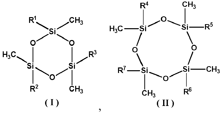
- the cyclosiloxane is selected from cyclotrisiloxane represented by formula I and/or cyclotetrasiloxane represented by formula II: where R 1 to R 7 are each independently selected from C1 to C4 alkyl or vinyl. Further optionally, the cyclosiloxane is selected from one or more of hexamethylcyclotrisiloxane represented by formula 1-1, octamethylcyclotetrasiloxane represented by formula II-1, or tetramethyltetravinylcyclotetrasiloxane represented by formula II-2.
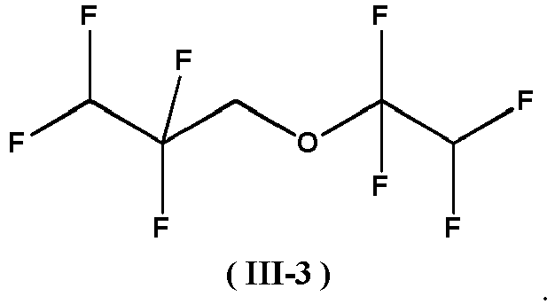
- the fluoroether has a structure represented by formula III: where R 8 and R 9 are each independently selected from a hydrogen atom, a fluorine atom, or a fluoroalkyl group that has 1 to 6 carbon atoms.
- the fluoroether is selected from one or more of 1H,1H,5H-octafluoropentyl-1,1,2,2-tetrafluoroethyl ether represented by formula III-1, 1,1,2,2-tetrafluoroethyl-2,2,2-trifluoroethyl ether represented by formula III-2, or 1,1,2,2-tetrafluoroethyl-2,2,3,3-tetrafluoropropyl ether represented by formula III-3:
- a mass percentage of the cyclosiloxane in the electrolyte is 0.1% to 2%.
- a mass percentage of the fluoroether in the electrolyte is 0.2% to 2%.
- the mass percentage of the cyclosiloxane in the electrolyte is 0.1% to 2%; and the mass percentage of the fluoroether in the electrolyte is 0.2% to 2%.
- Adjusting percentages of the cyclosiloxane compound and the fluoroether in the electrolyte can mediate and improve high-temperature cycling performance and high-temperature storage performance. Amounts of the cyclosiloxane compound and fluoroether used have great impact on high-temperature storage volume swelling rate, low-temperature discharge, and high-temperature cycling performance of the lithium-ion battery. In a case that the additive contents go beyond the ranges provided by this application, the high-temperature storage volume swelling rate, low-temperature discharge, and high-temperature cycling performance of the lithium-ion battery cannot be obviously improved.
- the additive of the electrolyte provided by this application further includes one or more of ethylene sulfate, methylene disulfonate, tris(trimethylsilane) phosphate, or tris(trimethylsilane) borate.
- the foregoing additive may further change contents of the positive electrode interface film and reduce the interface film impedance to improve the low-temperature performance of the lithium-ion battery.
- the mass percentage of the additive in the electrolyte may optionally be 0.1% to 2%.
- the non-aqueous solvent is selected from one or more of propylene carbonate, ethylene carbonate, dimethyl carbonate, diethyl carbonate, dipropyl carbonate, ethyl methyl carbonate, methyl propyl carbonate, vinylene carbonate, ethylene carbonate, fluoroethylene carbonate, methyl formate, ethyl acetate, methyl butyrate, methyl acrylate, ethylene sulfite, acrylic sulfite, dimethyl sulfate, diethylsulfite, 1,3-propanesulfonate, methylene disulfonate, anhydride, N-methylpyrrolidone, N-methylformamide, N-methylacetamide, acetonitrile, N,N-dimethylformamide, sulfolane, dimethyl sulfoxide, methyl sulfide, ⁇ -butyrolactone, tetrahydrofuran, fluorinecyclic-containing organic esters
- a lithium-ion battery in a second aspect of this application includes a positive electrode plate, a negative electrode plate, a separator between the positive electrode plate and the negative electrode plate, and an electrolyte, where the electrolyte is the electrolyte in the first aspect of this application.
- FIG. 1 is a perspective view of an embodiment of a lithium-ion battery 5.
- FIG. 2 is an exploded view of FIG. 1 .
- the lithium-ion battery 5 includes a housing 51, an electrode assembly 52, a top cover assembly 53, and an electrolyte (not shown).
- the electrode assembly 52 is accommodated in the housing 51.
- the quantity of electrode assemblies 52 is not limited, which may be one or more.
- the lithium-ion battery 5 shown in FIG. 1 is a tank type battery, but is not limited thereto.
- the lithium-ion battery 5 may be a pouch type battery, which means that the housing 51 is replaced by a metal plastic film and the top cover assembly 53 is omitted.
- the positive electrode plate contains a material that can extract and accept lithium ions
- the negative electrode plate contains a material that can accept and extract lithium ions.
- the electrolyte provided in this application is applicable to various lithium-ion battery systems, helping to improve high-temperature performance and low-temperature performance of various lithium-ion batteries.
- the positive electrode plate includes a positive electrode current collector and a positive electrode active material layer arranged on at least one surface of the positive electrode current collector, and the positive electrode active material layer includes LiNi (1-x-y) Co x M y O 2 , M being selected from Mn or Al, where 0 ⁇ x ⁇ 0.5, 0 ⁇ y ⁇ 0.5, and 0 ⁇ x+y ⁇ 0.5.
- the high-nickel material LiNi (1-x-y) Co x M y O 2 included in the positive electrode active material layer has become one of selectable positive electrode active materials for lithium-ion batteries with high energy density due to its higher theoretical specific capacity than other positive electrode active materials.
- the high-nickel positive electrode active material has some problems in use.
- a high nickel content makes oxidation of the high-nickel positive electrode active material extremely strong, resulting that the electrolyte is prone to have side reactions on a surface of the positive electrode; stronger alkaline of the material promotes side reactions; and unstable structure of the material makes it easy to elute nickel, cobalt, and manganese ions. All these problems lead to safety risks such as shorter service life and gassing of the lithium-ion battery.
- the cyclosiloxane compound included in the electrolyte in this application can capture metal ions.
- the interface film formed by using the cyclosiloxane and the fluoroether together can well stabilize a positive electrode interface. Therefore, the electrolyte in this application allows the lithium-ion battery including the high-nickel positive electrode active material to have better high-temperature performance.
- the following steps may be included: mixing the positive electrode active material, a binder, and a conductive agent to form a slurry, and applying the slurry on the positive electrode current collector.
- the positive electrode active material layer may further include a conductive agent and a binder.
- the conductive agent and the binder are not limited to any specific types or proportions, but may be selected according to actual needs.
- the binder typically includes fluorine-containing polyolefin binders. With respect to the fluorine-containing polyolefin binders, water is usually a good solvent. In other words, the fluorine-containing polyolefin binders usually exhibit good solubility in water.
- the fluorine-containing polyolefin binders may include but not be limited to polyvinylidene fluoride (PVDF), vinylidene fluoride copolymer or their modified (for example, modified by carboxylic acid, acrylic acid, or acrylonitrile) derivatives.
- PVDF polyvinylidene fluoride
- the amount of the binder used may not be too high because of the poor conductivity of the binder.
- the mass percentage of the binder in the positive electrode active substance layer is less than or equal to 2wt%, so as to obtain lower impedance of the electrode plate.
- the conductive agent of the positive electrode plate may be various conductive agents suitable for lithium-ion batteries in the field, and for example, may include but not be limited to a combination of one or more of acetylene black, conductive carbon black, vapor grown carbon fiber (VGCF), carbon nanotubes (CNT), Ketjen black, or the like.
- the weight of the conductive agent may be 1wt% to 10wt% of a total mass of the positive electrode material layer. More optionally, a weight ratio of the conductive agent to the positive electrode active substance in the positive electrode plate is greater than or equal to 1.5:95.5.
- the positive electrode current collector is also not limited to any specific type, but may be selected according to actual needs. In this application, the positive electrode current collector may typically be a layered body.
- the positive electrode current collector may typically be a structure or part that can collect current.
- the positive electrode current collector may be made of various materials suitable to serve as a positive electrode current collector for lithium-ion batteries in the field.
- the positive electrode current collector may include but not be limited to metal foil, and more specifically, may include but not be limited to nickel foil or aluminum foil.
- the negative electrode plate typically includes a negative electrode current collector and a negative electrode active material layer on a surface of the negative electrode current collector, and the negative electrode active material layer typically includes a negative electrode active material.
- the negative electrode active material may be various materials suitable to be the negative electrode active material of a lithium-ion battery in the art, for example, may be but is not limited to a combination of one or more of graphite, soft carbon, hard carbon, carbon fiber, mesophase carbon microspheres, silicon-based material, tin-based material, lithium titanate, or other metals that can form an alloy with lithium.
- the graphite may be selected from a combination of one or more of artificial graphite, natural graphite, or modified graphite.
- the silicon-based material may be selected from a combination of one or more of elemental silicon, a silicon-oxygen compound, a silicon-carbon composite, or a silicon alloy.
- the tin-based material may be selected from a combination of one or more of elemental tin, a tin-oxygen compound, or a tin alloy.
- the negative electrode current collector may typically be a structure or part that can collect current.
- the negative electrode current collector may be a variety of materials suitable to serve as the negative electrode current collector of a lithium-ion battery in the art.
- the negative electrode current collector may include but is not limited to metal foil, and more specifically, may include but not be limited to copper foil and the like.
- the negative electrode plate may be a lithium plate.
- the separator may be various materials suitable for lithium-ion batteries in the field, and for example, may include but not be limited to a combination of one or more of polyethylene, polypropylene, polyvinylidene fluoride, kevlar, polyethylene terephthalate, polytetrafluoroethylene, polyacrylonitrile, polyimide, polyamide, polyester, or natural fibers.
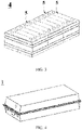
- FIG. 3 is a perspective view of an embodiment of a battery module 4.
- the battery module 4 includes a plurality of lithium-ion batteries 5.
- the plurality of batteries 5 are arranged in a longitudinal direction.
- the battery module 4 may be used as a power source or an energy storage device.
- the quantity of lithium-ion batteries 5 included in the battery module 4 may be adjusted based on use and capacity of the battery module 4.
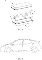
- FIG. 4 is a perspective view of an embodiment of a battery pack 1.
- FIG. 5 is an exploded view of FIG. 4 .
- the battery pack 1 includes an upper box body 2, a lower box body 3, and a battery module 4.
- the upper box body 2 and the lower box body 3 are combined to form a space for accommodating the battery module 4.
- the battery module 4 is disposed in the space formed by the upper box body 2 and the lower box body 3 that are combined.
- An output electrode of the battery module 4 penetrates through one or both of the upper box body 2 and the lower box body 3 to output power or receive charge from an outer source.
- the quantity and arrangement of the battery modules 4 used in the battery pack 1 may be determined depending on an actual need.
- the battery pack 1 may be used as a power source or an energy storage device.
- an apparatus that uses the battery 5 is an electric car.
- the apparatus that uses the battery 5 is not limited thereto. Rather, it may be any electric vehicles other than electric cars (for example, an electric bus, a tramcar, an electric bicycle, an electric motorbike, an electric scooter, an electric golf cart, and an electric truck), electric ships, electric tools, electronic devices, and energy storage systems.
- the electric car may be a battery electric car, a hybrid electric car, or a plug-in hybrid electric car.
- the apparatus provided in the fifth aspect of this application may include the battery module 4 described in the third aspect of this application.
- the apparatus provided in the fifth aspect of this application may alternatively include the battery pack 1 according to the fourth aspect of this application.
- the battery was discharged at 1C to 2.8V, and then was subjected to a high-temperature cycling test.
- the thermostat is heated to 60°C.
- the battery was charged at a constant current of 1C to 4.3V, then charged to a current of 0.05C, and discharged at a constant current of 1C to 2.8V
- a capacity retention rate (%) of the battery was calculated after 500 cycles of such charge and discharge at 60°C.
- Capacity retention rate (%) of the battery after 500 cycles at 60°C discharge capacity at the 500 th cycle/discharge capacity at the first cycle ⁇ 100%.
- Table 2 shows performance test results of Examples 1 to 19 and Comparative Examples 1 to 11. Table 2 Performance test results of Examples and Comparative Examples Volume swelling rate after storage for 3 days at 80°C Capacity retention rate under low-temperature discharge at -20°C Capacity retention rate after 500 cycles at 60°C Comparative Example 1 57.00% 62.90% 67.60% Comparative Example 2 56.50% 63.10% 68.00% Comparative Example 3 55.20% 64.10% 68.90% Comparative Example 4 35.80% 68.40% 74.60% Comparative Example 5 32.80% 70.50% 78.50% Comparative Example 6 32.40% 71.00% 78.80% Comparative Example 7 56.40% 62.80% 67.90% Comparative Example 8 56.30% 62.70% 68.80% Comparative Example 9 50.30% 60.50% 70.40% Comparative Example 10 46.30% 57.60% 71.80% Comparative Example 11 44.10% 55.90% 72.00% Example 1 53.40% 63.80% 69.40% Example 2 28.70% 65.70% 77.80%
- Example 2 and Comparative Examples 4 and 9 It can be seen from the test results of Example 2 and Comparative Examples 4 and 9 that the high-temperature cycling performance and high-temperature storage performance of the lithium-ion battery were significantly better when using the cyclosiloxane and fluoroether together than using only the cyclosiloxane or only the fluoroether. This is because when only the fluoroether is added in the electrolyte, the interface film formed by the fluoroether on the positive electrode plate is not dense enough to stabilize its appearance when the positive electrode changes in volume due to intercalation and deintercalation of lithium ions.
- the interface film formed by the cyclosiloxane on the positive electrode plate is prone to be decomposed during operation due to poor oxidation resistance of alkyl groups.
- the two additives will synergistically react on the surface of the positive electrode, combining silicon (and oxygen) containing groups and fluorine (and oxygen) containing groups to form an interface film containing silicon, oxygen, and fluorine, which not only ensures density of the interface film, but also strengthens oxidation resistance and thermal stability of the interface film, greatly improving both storage performance and cycling performance of the lithium-ion battery under high temperature.
Landscapes
- Chemical & Material Sciences (AREA)
- General Chemical & Material Sciences (AREA)
- Chemical Kinetics & Catalysis (AREA)
- Electrochemistry (AREA)
- Engineering & Computer Science (AREA)
- Manufacturing & Machinery (AREA)
- Inorganic Chemistry (AREA)
- General Physics & Mathematics (AREA)
- Condensed Matter Physics & Semiconductors (AREA)
- Physics & Mathematics (AREA)
- Materials Engineering (AREA)
- Aviation & Aerospace Engineering (AREA)
- Secondary Cells (AREA)
Abstract
Description
- This application claims priority to
Chinese Patent Application No. 201910996078.6, filed with the China National Intellectual Property Administration on October 18, 2019 - This application relates to the field of batteries, and in particular, to an electrolyte for lithium-ion battery, a lithium-ion battery, a battery module, a battery pack, and an apparatus.
- At present, lithium-ion batteries have been applied as a power source on a large scale in the automobile industry. As lithium-ion batteries are a good alternative to fuel, people are imposing higher requirements on their service life. Increasing energy density of lithium-ion batteries can not only improve their endurance capability, but also reduce the cost per unit power. One of effective methods to increase the energy density of lithium-ion batteries is to develop positive electrode materials with high specific capacity for lithium-ion batteries. The energy density can be increased by, for example, increasing gram capacity of active materials, or reducing weight of structural parts and auxiliary materials. High-nickel positive electrode materials are one of the best solutions to improve the energy density for their higher theoretical specific capacity than other positive electrode materials.
- However, present lithium-ion batteries still have problems such as unsatisfactory storage performance and cycling performance under high temperature.
- In view of the problems described in the background, the purpose of this application is to provide an electrolyte for lithium-ion battery, a lithium-ion battery, a battery module, a battery pack, and an apparatus. Storage performance and cycling performance of the lithium-ion battery under high temperature have been significantly improved.
- To achieve the above objective, a first aspect of this application provides an electrolyte for lithium-ion battery, including a non-aqueous solvent, and a lithium salt and an additive that are dissolved in the non-aqueous solvent, and the additive includes a cyclosiloxane and a fluoroether.
- A second aspect of this application provides a lithium-ion battery including a positive electrode plate, a negative electrode plate, a separator between the positive electrode plate and the negative electrode plate, and an electrolyte, where the electrolyte is the electrolyte provided in the first aspect of this application.
- A third aspect of this application provides a battery module including the lithium-ion battery in the second aspect of this application.
- A fourth aspect of this application provides a battery pack including the battery module in the third aspect of this application.
- A fifth aspect of this application provides an apparatus including the lithium-ion battery in the second aspect of this application, and the lithium-ion battery serves as a power source for the apparatus.
- Compared with the prior art, this application includes at least the following beneficial effects. The electrolyte provided in this application includes the cyclosiloxane additive and the fluoroether additive. Since silicon is more stable than carbon, the cyclosiloxane can have ring-opening polymerization reaction at high temperature to form a film on a surface of the positive electrode of the lithium-ion battery, thereby stabilizing a positive electrode interface. In addition, epoxy groups, with strong electron-withdrawing properties, can capture metal ions such as cobalt and manganese, thereby inhibiting deterioration of battery performance caused by dissolution of these ions. Since oxidation potential of the fluoroether is lower than that of the non-aqueous solvent, the fluoroether will preferentially form a film on a surface of the positive electrode of the lithium-ion battery, thereby inhibiting oxidative decomposition of the non-aqueous solvent. In addition, due to existence of fluoroalkyl atoms, the interface film formed by the fluoroether on the positive electrode of the lithium-ion battery has good thermal stability. However, the interface film formed by the fluoroether on the positive electrode is not dense enough to stabilize its appearance when the positive electrode changes in volume due to intercalation and deintercalation of lithium ions. The interface film formed by the cyclosiloxane on the positive electrode is prone to be decomposed during operation of the battery due to the poor oxidation resistance of alkyl groups. In the electrolyte provided in this application, the cyclosiloxane and the fluoroether are used together to synergistically react on a surface of the positive electrode, combining silicon (and oxygen) containing groups and fluorine (and oxygen) containing groups to form an interface film containing silicon, oxygen, and fluorine, which not only ensures density of the interface film, but also strengthens oxidation resistance and thermal stability of the interface film, greatly improving both storage performance and cycling performance of the lithium-ion battery under high temperature.
- The battery module, the battery pack, and the apparatus in this application include the lithium-ion battery, and therefore have at least the same advantages as that of the lithium-ion battery.
-
-
FIG. 1 is a perspective view of an embodiment of a battery; -
FIG. 2 is an exploded view of an embodiment of the battery; -
FIG. 3 is a perspective view of an embodiment of a battery module; -
FIG. 4 is a perspective view of an embodiment of a battery pack; -
FIG. 5 is an exploded view ofFIG. 4 ; and -
FIG. 6 is a schematic diagram of an embodiment of an apparatus using a battery as a power source. - Reference signs are described as follows:
- 1. battery pack;
- 2. upper box body;
- 3. lower box body;
- 4. battery module;
- 5. battery;
- 51. housing;
- 52. electrode assembly; and
- 53. top cover assembly.
- The following describes in detail an electrolyte for lithium-ion battery, a lithium-ion battery, a battery module, a battery pack, and an apparatus according to this application.
- An electrolyte for lithium-ion battery in a first aspect of this application includes a non-aqueous solvent, and a lithium salt and an additive that are dissolved in the non-aqueous solvent, where the additive includes a cyclosiloxane and a fluoroether.
- In the electrolyte provided in this application, the cyclosiloxane and the fluoroether are used together to synergistically react on a surface of the positive electrode of the lithium-ion battery, combining silicon (and oxygen) containing groups and fluorine (and oxygen) containing groups to form an interface film containing silicon, oxygen, and fluorine on the surface of the positive electrode. The interface film has not only great density, but also better oxidation resistance and thermal stability, greatly improving both storage performance and cycling performance of the lithium-ion battery under high temperature.
- Optionally, the cyclosiloxane is selected from cyclotrisiloxane represented by formula I and/or cyclotetrasiloxane represented by formula II:


- Optionally, the fluoroether has a structure represented by formula III:

- Further optionally, the fluoroether is selected from one or more of 1H,1H,5H-octafluoropentyl-1,1,2,2-tetrafluoroethyl ether represented by formula III-1, 1,1,2,2-tetrafluoroethyl-2,2,2-trifluoroethyl ether represented by formula III-2, or 1,1,2,2-tetrafluoroethyl-2,2,3,3-tetrafluoropropyl ether represented by formula III-3:


- Optionally, a mass percentage of the cyclosiloxane in the electrolyte is 0.1% to 2%.
- Optionally, a mass percentage of the fluoroether in the electrolyte is 0.2% to 2%.
- Optionally, the mass percentage of the cyclosiloxane in the electrolyte is 0.1% to 2%; and the mass percentage of the fluoroether in the electrolyte is 0.2% to 2%.
- Adjusting percentages of the cyclosiloxane compound and the fluoroether in the electrolyte can mediate and improve high-temperature cycling performance and high-temperature storage performance. Amounts of the cyclosiloxane compound and fluoroether used have great impact on high-temperature storage volume swelling rate, low-temperature discharge, and high-temperature cycling performance of the lithium-ion battery. In a case that the additive contents go beyond the ranges provided by this application, the high-temperature storage volume swelling rate, low-temperature discharge, and high-temperature cycling performance of the lithium-ion battery cannot be obviously improved. Moreover, when the cyclosiloxane compound content is excessively high, performance of the battery will not be significantly improved due to lower solubility; and when the fluoroether content is excessively high, the interface film impedance will increase, even deteriorating the low-temperature performance of the battery.
- Optionally, the additive of the electrolyte provided by this application further includes one or more of ethylene sulfate, methylene disulfonate, tris(trimethylsilane) phosphate, or tris(trimethylsilane) borate. The foregoing additive may further change contents of the positive electrode interface film and reduce the interface film impedance to improve the low-temperature performance of the lithium-ion battery. The mass percentage of the additive in the electrolyte may optionally be 0.1% to 2%.
- Optionally, the non-aqueous solvent is selected from one or more of propylene carbonate, ethylene carbonate, dimethyl carbonate, diethyl carbonate, dipropyl carbonate, ethyl methyl carbonate, methyl propyl carbonate, vinylene carbonate, ethylene carbonate, fluoroethylene carbonate, methyl formate, ethyl acetate, methyl butyrate, methyl acrylate, ethylene sulfite, acrylic sulfite, dimethyl sulfate, diethylsulfite, 1,3-propanesulfonate, methylene disulfonate, anhydride, N-methylpyrrolidone, N-methylformamide, N-methylacetamide, acetonitrile, N,N-dimethylformamide, sulfolane, dimethyl sulfoxide, methyl sulfide, γ-butyrolactone, tetrahydrofuran, fluorinecyclic-containing organic esters, sulfur-containing cyclic organic esters, or cyclic organic esters with unsaturated bonds.
- A lithium-ion battery in a second aspect of this application includes a positive electrode plate, a negative electrode plate, a separator between the positive electrode plate and the negative electrode plate, and an electrolyte, where the electrolyte is the electrolyte in the first aspect of this application.
-
FIG. 1 is a perspective view of an embodiment of a lithium-ion battery 5.FIG. 2 is an exploded view ofFIG. 1 . With reference toFIG. 1 and FIG. 2 , the lithium-ion battery 5 includes ahousing 51, anelectrode assembly 52, atop cover assembly 53, and an electrolyte (not shown). Theelectrode assembly 52 is accommodated in thehousing 51. The quantity ofelectrode assemblies 52 is not limited, which may be one or more. - It is noted that the lithium-
ion battery 5 shown inFIG. 1 is a tank type battery, but is not limited thereto. The lithium-ion battery 5 may be a pouch type battery, which means that thehousing 51 is replaced by a metal plastic film and thetop cover assembly 53 is omitted. - In the lithium-ion battery in this application, the positive electrode plate contains a material that can extract and accept lithium ions, and the negative electrode plate contains a material that can accept and extract lithium ions. The electrolyte provided in this application is applicable to various lithium-ion battery systems, helping to improve high-temperature performance and low-temperature performance of various lithium-ion batteries.
- Optionally, in the lithium-ion battery provided in this application, the positive electrode plate includes a positive electrode current collector and a positive electrode active material layer arranged on at least one surface of the positive electrode current collector, and the positive electrode active material layer includes LiNi(1-x-y)CoxMyO2, M being selected from Mn or Al, where 0≤x≤0.5, 0≤y≤0.5, and 0≤x+y≤0.5. The high-nickel material LiNi(1-x-y)CoxMyO2 included in the positive electrode active material layer has become one of selectable positive electrode active materials for lithium-ion batteries with high energy density due to its higher theoretical specific capacity than other positive electrode active materials. However, the high-nickel positive electrode active material has some problems in use. A high nickel content makes oxidation of the high-nickel positive electrode active material extremely strong, resulting that the electrolyte is prone to have side reactions on a surface of the positive electrode; stronger alkaline of the material promotes side reactions; and unstable structure of the material makes it easy to elute nickel, cobalt, and manganese ions. All these problems lead to safety risks such as shorter service life and gassing of the lithium-ion battery. The cyclosiloxane compound included in the electrolyte in this application can capture metal ions. In addition, the interface film formed by using the cyclosiloxane and the fluoroether together can well stabilize a positive electrode interface. Therefore, the electrolyte in this application allows the lithium-ion battery including the high-nickel positive electrode active material to have better high-temperature performance.
- Those skilled in the art may select a suitable method to prepare the positive electrode plate. For example, the following steps may be included: mixing the positive electrode active material, a binder, and a conductive agent to form a slurry, and applying the slurry on the positive electrode current collector.
- In the positive electrode plate in this application, the positive electrode active material layer may further include a conductive agent and a binder. The conductive agent and the binder are not limited to any specific types or proportions, but may be selected according to actual needs. The binder typically includes fluorine-containing polyolefin binders. With respect to the fluorine-containing polyolefin binders, water is usually a good solvent. In other words, the fluorine-containing polyolefin binders usually exhibit good solubility in water. For example, the fluorine-containing polyolefin binders may include but not be limited to polyvinylidene fluoride (PVDF), vinylidene fluoride copolymer or their modified (for example, modified by carboxylic acid, acrylic acid, or acrylonitrile) derivatives. In the positive electrode material layer, for the mass percentage of the binder, the amount of the binder used may not be too high because of the poor conductivity of the binder. Optionally, the mass percentage of the binder in the positive electrode active substance layer is less than or equal to 2wt%, so as to obtain lower impedance of the electrode plate. The conductive agent of the positive electrode plate may be various conductive agents suitable for lithium-ion batteries in the field, and for example, may include but not be limited to a combination of one or more of acetylene black, conductive carbon black, vapor grown carbon fiber (VGCF), carbon nanotubes (CNT), Ketjen black, or the like. The weight of the conductive agent may be 1wt% to 10wt% of a total mass of the positive electrode material layer. More optionally, a weight ratio of the conductive agent to the positive electrode active substance in the positive electrode plate is greater than or equal to 1.5:95.5. The positive electrode current collector is also not limited to any specific type, but may be selected according to actual needs. In this application, the positive electrode current collector may typically be a layered body. The positive electrode current collector may typically be a structure or part that can collect current. The positive electrode current collector may be made of various materials suitable to serve as a positive electrode current collector for lithium-ion batteries in the field. For example, the positive electrode current collector may include but not be limited to metal foil, and more specifically, may include but not be limited to nickel foil or aluminum foil. In the lithium-ion battery in this application, the negative electrode plate typically includes a negative electrode current collector and a negative electrode active material layer on a surface of the negative electrode current collector, and the negative electrode active material layer typically includes a negative electrode active material. The negative electrode active material may be various materials suitable to be the negative electrode active material of a lithium-ion battery in the art, for example, may be but is not limited to a combination of one or more of graphite, soft carbon, hard carbon, carbon fiber, mesophase carbon microspheres, silicon-based material, tin-based material, lithium titanate, or other metals that can form an alloy with lithium. The graphite may be selected from a combination of one or more of artificial graphite, natural graphite, or modified graphite. The silicon-based material may be selected from a combination of one or more of elemental silicon, a silicon-oxygen compound, a silicon-carbon composite, or a silicon alloy. The tin-based material may be selected from a combination of one or more of elemental tin, a tin-oxygen compound, or a tin alloy. The negative electrode current collector may typically be a structure or part that can collect current. The negative electrode current collector may be a variety of materials suitable to serve as the negative electrode current collector of a lithium-ion battery in the art. For example, the negative electrode current collector may include but is not limited to metal foil, and more specifically, may include but not be limited to copper foil and the like.
- In the lithium-ion battery in this application, the negative electrode plate may be a lithium plate. In the lithium-ion battery of this application, the separator may be various materials suitable for lithium-ion batteries in the field, and for example, may include but not be limited to a combination of one or more of polyethylene, polypropylene, polyvinylidene fluoride, kevlar, polyethylene terephthalate, polytetrafluoroethylene, polyacrylonitrile, polyimide, polyamide, polyester, or natural fibers.
-
FIG. 3 is a perspective view of an embodiment of abattery module 4. - Referring to
FIG. 3 , thebattery module 4 includes a plurality of lithium-ion batteries 5. The plurality ofbatteries 5 are arranged in a longitudinal direction. Thebattery module 4 may be used as a power source or an energy storage device. The quantity of lithium-ion batteries 5 included in thebattery module 4 may be adjusted based on use and capacity of thebattery module 4. -
FIG. 4 is a perspective view of an embodiment of abattery pack 1.FIG. 5 is an exploded view ofFIG. 4 . - Referring to
FIG. 4 andFIG. 5 , thebattery pack 1 includes anupper box body 2, alower box body 3, and abattery module 4. - The
upper box body 2 and thelower box body 3 are combined to form a space for accommodating thebattery module 4. Thebattery module 4 is disposed in the space formed by theupper box body 2 and thelower box body 3 that are combined. An output electrode of thebattery module 4 penetrates through one or both of theupper box body 2 and thelower box body 3 to output power or receive charge from an outer source. The quantity and arrangement of thebattery modules 4 used in thebattery pack 1 may be determined depending on an actual need. Thebattery pack 1 may be used as a power source or an energy storage device. - In
FIG. 6 , an apparatus that uses thebattery 5 is an electric car. Certainly, the apparatus that uses thebattery 5 is not limited thereto. Rather, it may be any electric vehicles other than electric cars (for example, an electric bus, a tramcar, an electric bicycle, an electric motorbike, an electric scooter, an electric golf cart, and an electric truck), electric ships, electric tools, electronic devices, and energy storage systems. The electric car may be a battery electric car, a hybrid electric car, or a plug-in hybrid electric car. Certainly, depending on an actual use form, the apparatus provided in the fifth aspect of this application may include thebattery module 4 described in the third aspect of this application. Certainly, the apparatus provided in the fifth aspect of this application may alternatively include thebattery pack 1 according to the fourth aspect of this application. - This application is further described with reference to specific Examples. It should be understood that these embodiments are merely used to describe this application but not to limit the scope of this application.
- The electrolytes and lithium-ion batteries in Examples 1 to 19 and Comparative Examples 1 to 11 were all prepared according to the following method.
- (1) Preparation of a positive electrode plate: A positive electrode active material, a conductive agent carbon black (Super P), and a binder polyvinylidene fluoride (PVDF) were mixed at a mass ratio of 97:1.5:1.5, and added to a solvent N-methylpyrrolidone (NMP). The mixture was stirred by a vacuum mixer to obtain a uniform and transparent positive electrode active material slurry. Then the positive electrode active material slurry was uniformly applied on an aluminum foil positive electrode current collector and dried, followed by cold pressing, edge trimming, cutting, and slitting, to obtain a positive electrode plate.
- (2) Preparation of a negative electrode plate: A negative electrode active material, a conductive agent carbon black (Super P), a thickener sodium carboxymethyl cellulose (CMC), and a binder styrene butadiene rubber (SBR) were mixed at a mass ratio of 96.4:1.5:0.5:1.6, and added to a solvent deionized water. The mixture was stirred by a vacuum mixer to obtain a uniform negative electrode active material slurry. Then the negative electrode active material slurry was uniformly applied on a copper foil negative electrode current collector and dried, followed by cold pressing, edge trimming, cutting, and slitting, to obtain a negative electrode plate.
- (3) Preparation of a separator: A polyethylene film (PE) was used as a separator.
- (4) Preparation of an electrolyte: Ethylene carbonate (EC), ethyl methyl carbonate (EMC), and diethyl carbonate (DEC) were mixed at a mass ratio of 27:3:30:40, and a lithium salt which was 1.1 mol/L LiPF6 was resolved in the mixture solvent. Then cyclosiloxane and fluoroether were added and other additives were added optionally. The resulting mixture was mixed thoroughly to obtain a uniform electrolyte. The specific types and contents in the electrolyte are shown in Table 1. In Table 1, the cyclosiloxane compound content and the fluoroether content are both weight percentages calculated based on a total weight of the electrolyte.
- (5) Preparation of a lithium-ion battery: The positive electrode plate, the separator, and the negative electrode plate were stacked in sequence, so that the separator was located between the positive electrode plate and the negative electrode plate, and the stack was wound into a battery cell. The battery cell was packed into a packing housing, with the electrolyte made above injected, followed by sealing, standing, hot pressing, cold pressing, and formation to obtain a lithium-ion battery.
- Parameters of secondary lithium-ion batteries in Examples 1 to 19 and Comparative Examples 1 to 11 are shown in Table 1.
Table 1 Specific parameters of Examples and Comparative Examples Battery system Additive 1: cyclosiloxa ne compound Additive 2: fluoroether Additive 3: others Ty pe Conte nt Ty pe Conte nt Type Content Comparative Example 1 LiNi0.8Co0.1Mn0.1O2/graphi te / / / / / / Comparative Example 2 LiNi0.8Co0.1Mn0.1O2/graphi te 1-1 0.05 % / / / / Comparative Example 3 LiNi0.8Co0.1Mn0.1O2/graphi te 1-1 0.10 % / / / / Comparative Example 4 LiNi0.8Co0.1Mn0.1O2/graphi te 1-1 1.00 % / / / / Comparative Example 5 LiNi0.8Co0.1Mn0.1O2/graphi te 1-1 2.00 % / / / / Comparative Example 6 LiNi0.8Co0.1Mm0.1O2/graphi te 1-1 2.50 % / / / / Comparative Example 7 LiNi0.8Co0.1Mn0.1O2/graphi te / / III-1 0.10 % / / Comparative Example 8 LiNi0.8Co0.1Mn0.1O2/graphi te / / III-1 0.20 % / / Comparative Example 9 LiNi0.8Co0.1Mn0.1O2/graphi te / / III-1 1.00 % / / Comparative Example 10 LiNi0.8Co0.1Mn0.1O2/graphi te / / III-1 2.00 % / / Comparative Example 11 LiNi0.8Co0.1Mn0.1O2/graphi te / / III-1 2.50 % / / Example 1 LiNi0.8Co0.1Mn0.1O2/graphi te 1-1 0.10 % III-1 0.20 % / / Example 2 LiNi0.8Co0.1Mn0.1O2/graphi te 1-1 1.00 % III-1 1.00 % / / Example 3 LiNi0.8Co0.1Mn0.1O2/graphi te 1-1 1.00 % III-1 2.00 % / / Example 4 LiNi0.8Co0.1Mn0.1O2/graphi te 1-1 1.00 % III-1 2.00 % Methylene disulfonate 0.30% Example 5 LiNi0.8Co0.1Mn0.1O2/graphi te 1-1 2.00 % III-1 1.00 % / / Example 6 LiNi0.8Co0.1Mn0.1O2/graphi te 1-1 2.00 % III-1 1.00 % Methylene disulfonate 0.50% Example 7 LiNi0.8Co0.1Mn0.1O2/graphi te II-1 1.00 % III-1 2.00 % / / Example 8 LiNi0.8Co0.1Mn0.1O2/graphi te II-2 1.00 % III-1 2.00 % / / Example 9 LiNi0.8Co0.1Mn0.1O2/graphi te II-2 1.00 % III-1 2.00 % Tris(trimethylsilane) borate 0.50% Example 10 LiNi0.8Co0.1Mn0.1O2/graphi te II-1 1.00 % III-2 2.00 % / / Example 11 LiNi0.8Co0.1Mn0.1O2/graphi te II-1 1.00 % III-2 2.00 % Tris(trimethylsilane) phosphate 0.50% Example 12 LiNi0.8Co0.1Mn0.1O2/graphi te II-1 1.00 % III-3 2.00 % / / Example 13 LiNi0.8Co0.1Mn0.1O2/graphi te II-1 1.50 % III-3 1.50 % / / Example 14 LiNi0.8Co0.1Mn0.1O2/graphi te 1-1 1.00 % III-2 0.50 % Methylene disulfonate 0.30% Example 15 LiNi0.8Co0.1Mn0.1O2/graphi te II-2 2.00 % III-3 1.00 % Tris(trimethylsilane) borate 0.50% Example 16 LiNi0.6Co0.2Mn0.2O2/graphi te 1-1 1.50 % III-1 0.50 % Methylene disulfonate 0.50% Example 18 LiNi0.5Co0.2Mn0.3O2/graphi te II-1 1.00 % III-3 0.50 % Tris(trimethylsilane) borate 0.30% Example 19 LiNi0.8Co0.1Mn0.1O2/graphi te+SiO) C1 2.00 % III-2 1.00 % Tris(trimethylsilane) phosphate 0.30% (Note: "/" means no addition of the corresponding substance, and contents of additive 1, additive 2, and additive 3 all mean mass percentages of the additives in the electrolyte.) - The lithium-ion batteries in Examples 1 to 19 and Comparative Examples 1 to 11 were tested separately as follows.
- The lithium-ion battery was left at 25°C for 30 min. After that, it was charged at a constant current of 1C to a voltage of 4.3V, and then charged at a constant voltage of 4.3V to a current of 0.05C. A volume of the lithium-ion battery was measured then and recorded as V0. The lithium-ion battery was placed in a 80°C thermostat and was taken out 3 days later. A volume of the lithium-ion battery was measured then and recorded as V1. (In this test, the volume of the lithium-ion battery was measured by using a drainage method.)

- At 25°C, the lithium-ion battery was discharged to 2.8V at 1C, then charged at a constant current of 0.05C to 4.3V, and its charge capacity was recorded as CC. Then the temperature of the thermostat was adjusted to -20°C, the lithium-ion battery was discharged to 2.8V at a constant current of 1C, and its discharge capacity was recorded as CDT. A ratio of the discharge capacity to the charge capacity is a discharge capacity retention rate.

- At 25 °C, the battery was discharged at 1C to 2.8V, and then was subjected to a high-temperature cycling test. The thermostat is heated to 60°C. The battery was charged at a constant current of 1C to 4.3V, then charged to a current of 0.05C, and discharged at a constant current of 1C to 2.8V A capacity retention rate (%) of the battery was calculated after 500 cycles of such charge and discharge at 60°C.
- Capacity retention rate (%) of the battery after 500 cycles at 60°C = discharge capacity at the 500th cycle/discharge capacity at the first cycle × 100%.
- Table 2 shows performance test results of Examples 1 to 19 and Comparative Examples 1 to 11.
Table 2 Performance test results of Examples and Comparative Examples Volume swelling rate after storage for 3 days at 80°C Capacity retention rate under low-temperature discharge at -20°C Capacity retention rate after 500 cycles at 60°C Comparative Example 1 57.00% 62.90% 67.60% Comparative Example 2 56.50% 63.10% 68.00% Comparative Example 3 55.20% 64.10% 68.90% Comparative Example 4 35.80% 68.40% 74.60% Comparative Example 5 32.80% 70.50% 78.50% Comparative Example 6 32.40% 71.00% 78.80% Comparative Example 7 56.40% 62.80% 67.90% Comparative Example 8 56.30% 62.70% 68.80% Comparative Example 9 50.30% 60.50% 70.40% Comparative Example 10 46.30% 57.60% 71.80% Comparative Example 11 44.10% 55.90% 72.00% Example 1 53.40% 63.80% 69.40% Example 2 28.70% 65.70% 77.80% Example 3 25.50% 61.70% 79.40% Example 4 25.20% 63.70% 80.50% Example 5 21.40% 69.20% 81.30% Example 6 20.90% 73.20% 82.50% Example 7 24.70% 62.30% 80.10% Example 8 22.30% 55.20% 83.10% Example 9 21.80% 62.90% 84.00% Example 10 25.00% 63.40% 79.60% Example 11 24.60% 67.90% 80.20% Example 12 24.30% 67.20% 79.70% Example 13 22.80% 68.40% 80.20% Example 14 31.30% 78.50% 77.50% Example 15 17.90% 61.50% 88.60% Example 16 14.70% 82.30% 90.20% Example 18 13.20% 84.10% 92.50% Example 19 35.70% 67.80% 78.50% - It can be seen from the test results of Comparative Examples 1 to 11 that the amounts of the cyclosiloxane compound and fluoroether used had great impact on high-temperature storage volume swelling rate, low-temperature discharge performance, and high-temperature cycling performance of the lithium-ion battery. In a case that the additive contents went beyond the ranges provided by this application, the high-temperature storage volume swelling rate, low-temperature discharge performance, and high-temperature cycling performance of the lithium-ion battery could not be obviously improved. When the cyclosiloxane compound content was excessively high, performance of the battery would not be significantly improved due to lower solubility; and when the fluoroether content was excessively high, the interface film impedance would increase, deteriorating the low-temperature performance of the battery.
- It can be seen from the test results of Example 2 and Comparative Examples 4 and 9 that the high-temperature cycling performance and high-temperature storage performance of the lithium-ion battery were significantly better when using the cyclosiloxane and fluoroether together than using only the cyclosiloxane or only the fluoroether. This is because when only the fluoroether is added in the electrolyte, the interface film formed by the fluoroether on the positive electrode plate is not dense enough to stabilize its appearance when the positive electrode changes in volume due to intercalation and deintercalation of lithium ions. Similarly, when only the cyclosiloxane is added in the electrolyte, the interface film formed by the cyclosiloxane on the positive electrode plate is prone to be decomposed during operation due to poor oxidation resistance of alkyl groups. When the cyclosiloxane and the fluoroether are added together to the electrolyte, the two additives will synergistically react on the surface of the positive electrode, combining silicon (and oxygen) containing groups and fluorine (and oxygen) containing groups to form an interface film containing silicon, oxygen, and fluorine, which not only ensures density of the interface film, but also strengthens oxidation resistance and thermal stability of the interface film, greatly improving both storage performance and cycling performance of the lithium-ion battery under high temperature.
- It can be seen from the test results of Examples 3 to 15 that adjusting the cyclosiloxane compound and fluoroether contents in the electrolyte could mediate and improve high-temperature cycling performance and high-temperature storage performance. In addition, adding additives with low impedance such as tris(trimethylsilane) borate allowed the lithium-ion battery to have a better low-temperature performance.
- It can be seen from the test results of Examples 16 to 19 that, in lithium-ion battery systems with other positive electrode and negative electrode materials, using the cyclosiloxane compound and fluoroether together in the electrolyte, or further adding other additives with low impedance could also allow the lithium-ion battery to have a better high-temperature performance and a better low-temperature performance.
- According to the disclosure and teaching of this specification, a person skilled in the art may make further changes or modifications to the foregoing embodiments. Therefore, this application is not limited to the foregoing disclosure and the described embodiments, and changes or modifications to this application shall also fall within the protection scope of the claims of this application. In addition, although some specific terms are used in this specification, these terms are used only for ease of description, and do not constitute any limitation on this application.
Claims (14)
- An electrolyte for lithium-ion battery, wherein the electrolyte comprises a non-aqueous solvent, and a lithium salt and an additive that are dissolved in the non-aqueous solvent, and the additive comprises a cyclosiloxane and a fluoroether.
- The electrolyte according to claim 1, wherein the cyclosiloxane is selected from cyclotrisiloxane represented by formula I and/or cyclotetrasiloxane represented by formula II:

- The electrolyte according to claim 2, wherein the cyclosiloxane is selected from one or more of structures represented by formula 1-1, formula II-1, and formula II-2:

- The electrolyte according to any one of claims 1 to 3, wherein the fluoroether has a structure represented by formula III:

- The electrolyte according to claim 4, wherein the fluoroether is selected from one or more of formulas III-1 to III-3:

- The electrolyte according to any one of claims 1 to 5, wherein a mass percentage of the cyclosiloxane in the electrolyte is 0.1% to 2%; and/or a mass percentage of the fluoroether in the electrolyte is 0.2% to 2%.
- The electrolyte according to any one of claims 1 to 6, wherein the additive further comprises one or more of ethylene sulfate, methylene disulfonate, tris(trimethylsilane) phosphate, or tris(trimethylsilane) borate.
- The electrolyte according to any one of claims 1 to 7, wherein the non-aqueous solvent is selected from one or more of propylene carbonate, ethylene carbonate, dimethyl carbonate, diethyl carbonate, dipropyl carbonate, ethyl methyl carbonate, methyl propyl carbonate, vinylene carbonate, ethylene carbonate, fluoroethylene carbonate, methyl formate, ethyl acetate, methyl butyrate, methyl acrylate, ethylene sulfite, acrylic sulfite, dimethyl sulfate, diethylsulfite, 1,3-propanesulfonate, methylene disulfonate, anhydride, N-methylpyrrolidone, N-methylformamide, N-methylacetamide, acetonitrile, N,N-dimethylformamide, sulfolane, dimethyl sulfoxide, methyl sulfide, γ-butyrolactone, tetrahydrofuran, fluorinecyclic-containing organic esters, sulfur-containing cyclic organic esters, or cyclic organic esters with unsaturated bonds.
- A lithium-ion battery, comprising a positive electrode plate, a negative electrode plate, a separator between the positive electrode plate and the negative electrode plate, and an electrolyte, wherein the electrolyte is the electrolyte according to any one of claims 1 to 8.
- The lithium-ion battery according to claim 9, wherein the positive electrode plate comprises a positive electrode current collector and a positive electrode active material layer arranged on at least one surface of the positive electrode current collector, and the positive electrode active material layer comprises LiNi(1-x-y)CoxMyO2, M being selected from Mn or Al, wherein 0≤x≤0.5, 0≤y≤0.5, and 0≤x+y≤0.5.
- A battery module, comprising the lithium-ion battery according to either one of claims 9 and 10.
- A battery pack, comprising the battery module according to claim 11.
- An apparatus, comprising the lithium-ion battery according to either one of claims 9 and 10, wherein the lithium-ion battery serves as a power source for the apparatus.
- The apparatus according to claim 13, wherein the apparatus comprises an electric vehicle, a hybrid electric vehicle, a plug-in hybrid electric vehicle, an electric bicycle, an electric scooter, an electric golf cart, an electric truck, an electric vessel, or an energy storage system.
Applications Claiming Priority (2)
| Application Number | Priority Date | Filing Date | Title |
|---|---|---|---|
| CN201910996078.6A CN110767939B (en) | 2019-10-18 | 2019-10-18 | Electrolyte for lithium ion battery, battery module, battery pack and device |
| PCT/CN2020/120305 WO2021073464A1 (en) | 2019-10-18 | 2020-10-12 | Electrolyte for lithium-ion battery, lithium-ion battery, battery module, battery pack, and device |
Publications (3)
| Publication Number | Publication Date |
|---|---|
| EP3979385A1 true EP3979385A1 (en) | 2022-04-06 |
| EP3979385A4 EP3979385A4 (en) | 2023-08-02 |
| EP3979385B1 EP3979385B1 (en) | 2026-04-08 |
Family
ID=69332428
Family Applications (1)
| Application Number | Title | Priority Date | Filing Date |
|---|---|---|---|
| EP20877732.6A Active EP3979385B1 (en) | 2019-10-18 | 2020-10-12 | Electrolyte for lithium-ion battery, lithium-ion battery, battery module, battery pack, and device |
Country Status (4)
| Country | Link |
|---|---|
| US (1) | US12476280B2 (en) |
| EP (1) | EP3979385B1 (en) |
| CN (1) | CN110767939B (en) |
| WO (1) | WO2021073464A1 (en) |
Cited By (2)
| Publication number | Priority date | Publication date | Assignee | Title |
|---|---|---|---|---|
| US20210328284A1 (en) * | 2019-01-10 | 2021-10-21 | Lg Chem, Ltd. | Battery Pack Manufacturing Method |
| US12438194B2 (en) | 2024-03-06 | 2025-10-07 | Lyten, Inc. | Electrolyte systems including chalcogenides and compound containing electron withdrawing group, and electrochemical cell including the same |
Families Citing this family (13)
| Publication number | Priority date | Publication date | Assignee | Title |
|---|---|---|---|---|
| CN110767939B (en) * | 2019-10-18 | 2021-06-11 | 宁德时代新能源科技股份有限公司 | Electrolyte for lithium ion battery, battery module, battery pack and device |
| CN112400249A (en) * | 2020-03-24 | 2021-02-23 | 宁德新能源科技有限公司 | Electrolyte and electrochemical device |
| KR102888101B1 (en) * | 2020-06-26 | 2025-11-19 | 미쯔비시 케미컬 주식회사 | Non-aqueous electrolyte and non-aqueous electrolyte battery |
| CN112018431B (en) * | 2020-09-02 | 2022-07-15 | 安徽天时新能源科技有限公司 | Electrolyte for high-temperature lithium battery |
| CN112271338B (en) * | 2020-11-27 | 2022-10-11 | 中创新航技术研究院(江苏)有限公司 | Electrolyte and lithium ion battery containing same |
| CN112768770A (en) * | 2021-01-19 | 2021-05-07 | 惠州锂威新能源科技有限公司 | Electrolyte and lithium ion battery containing same |
| CN113328139B (en) * | 2021-04-30 | 2022-05-20 | 惠州锂威新能源科技有限公司 | Electrolyte for lithium ion battery and lithium ion battery |
| CN113839093A (en) * | 2021-09-16 | 2021-12-24 | 湖州昆仑亿恩科电池材料有限公司 | Non-aqueous electrolyte of lithium ion battery and application thereof |
| KR102730191B1 (en) | 2021-09-24 | 2024-11-15 | 컨템포러리 엠퍼렉스 테크놀로지 (홍콩) 리미티드 | Lithium ion batteries, battery modules, battery packs and electrical devices |
| CN114335732A (en) * | 2022-01-06 | 2022-04-12 | 中化国际(控股)股份有限公司 | Lithium ion battery electrolyte |
| CN115954543A (en) * | 2022-12-28 | 2023-04-11 | 珠海冠宇电池股份有限公司 | a battery |
| KR20240136796A (en) * | 2023-03-07 | 2024-09-19 | 주식회사 엘지에너지솔루션 | Lithium secondary battery |
| CN119864501A (en) * | 2023-10-20 | 2025-04-22 | 北京车和家汽车科技有限公司 | Electrolyte and lithium battery comprising same |
Family Cites Families (13)
| Publication number | Priority date | Publication date | Assignee | Title |
|---|---|---|---|---|
| KR101179397B1 (en) * | 2006-11-15 | 2012-09-04 | 주식회사 엘지화학 | Non-aqueous electrolyte and electrochemical device comprising the same |
| JP5245404B2 (en) * | 2007-12-28 | 2013-07-24 | ダイキン工業株式会社 | Non-aqueous electrolyte |
| KR20150034261A (en) * | 2012-07-17 | 2015-04-02 | 도요타지도샤가부시키가이샤 | Lithium secondary cell and method for manufacturing same |
| KR101535865B1 (en) * | 2013-09-17 | 2015-07-14 | 파낙스 이텍(주) | electrolyte for secondary battery containing boron-based lithium salt and a secondary battery containing the same |
| WO2015069271A1 (en) * | 2013-11-08 | 2015-05-14 | Empire Technology Development Llc | Fluorinated siloxanes and methods for their preparation |
| CN105745779B (en) * | 2013-12-25 | 2021-02-05 | 旭化成株式会社 | Composition for addition to electrolyte solution containing silyl group-containing compound, electrolyte solution, and lithium ion secondary battery |
| KR101935013B1 (en) * | 2015-09-25 | 2019-01-03 | 주식회사 엘지화학 | Battery module, battery pack comprising the battery module and vehicle comprising the battery pack |
| CN105355975B (en) * | 2015-10-20 | 2018-08-21 | 宁德新能源科技有限公司 | electrolyte and lithium ion battery including the electrolyte |
| JP6260735B1 (en) * | 2016-07-06 | 2018-01-17 | セントラル硝子株式会社 | Non-aqueous electrolyte and non-aqueous electrolyte secondary battery using the same |
| CN107293792A (en) * | 2017-08-21 | 2017-10-24 | 宁波诺丁汉大学 | A kind of nonaqueous electrolytic solution and nickelic tertiary cathode material battery |
| CA3098915A1 (en) * | 2018-01-09 | 2019-07-18 | South Dakota Board Of Regents | Layered high capacity electrodes |
| CN113690481B (en) * | 2019-07-10 | 2022-08-05 | 宁德时代新能源科技股份有限公司 | Lithium ion battery and electric equipment comprising same |
| CN110767939B (en) * | 2019-10-18 | 2021-06-11 | 宁德时代新能源科技股份有限公司 | Electrolyte for lithium ion battery, battery module, battery pack and device |
-
2019
- 2019-10-18 CN CN201910996078.6A patent/CN110767939B/en active Active
-
2020
- 2020-10-12 WO PCT/CN2020/120305 patent/WO2021073464A1/en not_active Ceased
- 2020-10-12 EP EP20877732.6A patent/EP3979385B1/en active Active
-
2022
- 2022-03-23 US US17/702,653 patent/US12476280B2/en active Active
Cited By (3)
| Publication number | Priority date | Publication date | Assignee | Title |
|---|---|---|---|---|
| US20210328284A1 (en) * | 2019-01-10 | 2021-10-21 | Lg Chem, Ltd. | Battery Pack Manufacturing Method |
| US12119466B2 (en) * | 2019-01-10 | 2024-10-15 | Lg Energy Solution, Ltd. | Battery pack manufacturing method |
| US12438194B2 (en) | 2024-03-06 | 2025-10-07 | Lyten, Inc. | Electrolyte systems including chalcogenides and compound containing electron withdrawing group, and electrochemical cell including the same |
Also Published As
| Publication number | Publication date |
|---|---|
| CN110767939A (en) | 2020-02-07 |
| US20220216518A1 (en) | 2022-07-07 |
| US12476280B2 (en) | 2025-11-18 |
| CN110767939B (en) | 2021-06-11 |
| EP3979385A4 (en) | 2023-08-02 |
| WO2021073464A1 (en) | 2021-04-22 |
| EP3979385B1 (en) | 2026-04-08 |
Similar Documents
| Publication | Publication Date | Title |
|---|---|---|
| EP3979385B1 (en) | Electrolyte for lithium-ion battery, lithium-ion battery, battery module, battery pack, and device | |
| US20220149437A1 (en) | Lithium-ion battery, and related battery module, battery pack, and apparatus | |
| EP2958183B1 (en) | Electrolyte solution and lithium ion secondary battery provided with same | |
| EP3979384A1 (en) | Electrolyte for lithium ion battery, lithium ion battery, battery module, battery pack and device | |
| CN111525190B (en) | Electrolyte and lithium ion battery | |
| EP3951986B1 (en) | Electrolyte, lithium ion battery and device containing lithium ion battery | |
| EP4231407A1 (en) | Electrolyte solution, secondary battery comprising same, and preparation method for secondary battery | |
| US11961969B2 (en) | Nonaqueous electrolyte, lithium-ion battery, battery module, battery pack, and apparatus | |
| US11901511B2 (en) | Nonaqueous electrolyte, lithium-ion battery, battery module, battery pack, and apparatus | |
| EP3836279B1 (en) | Non-aqueous electrolyte, lithium-ion battery, battery module, battery pack, and device | |
| US12107227B2 (en) | Nonaqueous electrolyte, lithium-ion battery, battery module, battery pack, and apparatus | |
| KR20190130488A (en) | Electrolyte and lithium secondary battery comprising the same | |
| WO2024152720A1 (en) | Electrolyte for secondary battery, secondary battery, battery module, battery pack, and electrical device | |
| US20260011786A1 (en) | Electrolyte solution, battery and electrical device | |
| EP3832771B1 (en) | Non-aqueous electrolyte, lithium-ion battery, battery module, battery pack and device | |
| EP4421916A1 (en) | Lithium-ion secondary battery, battery module, battery pack, and electric apparatus | |
| EP4456232A1 (en) | Electrochemical device and electronic device | |
| JP5848587B2 (en) | Lithium secondary battery | |
| US12068457B2 (en) | Nonaqueous electrolyte compositions for lithium-ion battery | |
| EP4607648A1 (en) | Electrolyte, battery and electric device | |
| CN119764560B (en) | Electrolytes, lithium-ion batteries and electrical equipment | |
| EP4723282A1 (en) | Electrolyte, secondary battery, and electrical apparatus | |
| EP4597665A1 (en) | Non-aqueous electrolyte secondary battery | |
| EP4597666A1 (en) | Nonaqueous electrolyte secondary battery | |
| KR20190124505A (en) | Electrolyte and Lithium Metal Electrode Comprising the Same |
Legal Events
| Date | Code | Title | Description |
|---|---|---|---|
| STAA | Information on the status of an ep patent application or granted ep patent |
Free format text: STATUS: THE INTERNATIONAL PUBLICATION HAS BEEN MADE |
|
| PUAI | Public reference made under article 153(3) epc to a published international application that has entered the european phase |
Free format text: ORIGINAL CODE: 0009012 |
|
| STAA | Information on the status of an ep patent application or granted ep patent |
Free format text: STATUS: REQUEST FOR EXAMINATION WAS MADE |
|
| 17P | Request for examination filed |
Effective date: 20211230 |
|
| AK | Designated contracting states |
Kind code of ref document: A1 Designated state(s): AL AT BE BG CH CY CZ DE DK EE ES FI FR GB GR HR HU IE IS IT LI LT LU LV MC MK MT NL NO PL PT RO RS SE SI SK SM TR |
|
| DAV | Request for validation of the european patent (deleted) | ||
| DAX | Request for extension of the european patent (deleted) | ||
| A4 | Supplementary search report drawn up and despatched |
Effective date: 20230704 |
|
| RIC1 | Information provided on ipc code assigned before grant |
Ipc: H01M 10/0525 20100101ALI20230628BHEP Ipc: H01M 50/204 20210101ALI20230628BHEP Ipc: H01M 50/249 20210101ALI20230628BHEP Ipc: H01M 4/525 20100101ALI20230628BHEP Ipc: H01M 10/42 20060101ALI20230628BHEP Ipc: H01M 10/0569 20100101ALI20230628BHEP Ipc: H01M 10/0567 20100101AFI20230628BHEP |
|
| RAP1 | Party data changed (applicant data changed or rights of an application transferred) |
Owner name: CONTEMPORARY AMPEREX TECHNOLOGY(HONG KONG) LIMITED |
|
| RIC1 | Information provided on ipc code assigned before grant |
Ipc: H01M 10/0567 20100101AFI20250623BHEP Ipc: H01M 10/0569 20100101ALI20250623BHEP Ipc: H01M 10/42 20060101ALI20250623BHEP Ipc: H01M 4/525 20100101ALI20250623BHEP Ipc: H01M 50/249 20210101ALI20250623BHEP Ipc: H01M 50/204 20210101ALI20250623BHEP Ipc: H01M 10/0525 20100101ALI20250623BHEP |
|
| STAA | Information on the status of an ep patent application or granted ep patent |
Free format text: STATUS: EXAMINATION IS IN PROGRESS |
|
| 17Q | First examination report despatched |
Effective date: 20250818 |
|
| GRAP | Despatch of communication of intention to grant a patent |
Free format text: ORIGINAL CODE: EPIDOSNIGR1 |
|
| STAA | Information on the status of an ep patent application or granted ep patent |
Free format text: STATUS: GRANT OF PATENT IS INTENDED |
|
| INTG | Intention to grant announced |
Effective date: 20251110 |
|
| GRAS | Grant fee paid |
Free format text: ORIGINAL CODE: EPIDOSNIGR3 |
|
| GRAA | (expected) grant |
Free format text: ORIGINAL CODE: 0009210 |
|
| STAA | Information on the status of an ep patent application or granted ep patent |
Free format text: STATUS: THE PATENT HAS BEEN GRANTED |
|
| AK | Designated contracting states |
Kind code of ref document: B1 Designated state(s): AL AT BE BG CH CY CZ DE DK EE ES FI FR GB GR HR HU IE IS IT LI LT LU LV MC MK MT NL NO PL PT RO RS SE SI SK SM TR |
|
| REG | Reference to a national code |
Ref country code: CH Ref legal event code: F10 Free format text: ST27 STATUS EVENT CODE: U-0-0-F10-F00 (AS PROVIDED BY THE NATIONAL OFFICE) Effective date: 20260408 Ref country code: GB Ref legal event code: FG4D |
|
| REG | Reference to a national code |
Ref country code: DE Ref legal event code: R096 Ref document number: 602020070191 Country of ref document: DE |