EP3979275A1 - Sound and vibration damping system for transformer tanks and reactor tanks - Google Patents
Sound and vibration damping system for transformer tanks and reactor tanks Download PDFInfo
- Publication number
- EP3979275A1 EP3979275A1 EP20199995.0A EP20199995A EP3979275A1 EP 3979275 A1 EP3979275 A1 EP 3979275A1 EP 20199995 A EP20199995 A EP 20199995A EP 3979275 A1 EP3979275 A1 EP 3979275A1
- Authority
- EP
- European Patent Office
- Prior art keywords
- tank
- metal sheet
- viscoelastic layer
- tank wall
- stud bolts
- Prior art date
- Legal status (The legal status is an assumption and is not a legal conclusion. Google has not performed a legal analysis and makes no representation as to the accuracy of the status listed.)
- Pending
Links
Images


Classifications
-
- F—MECHANICAL ENGINEERING; LIGHTING; HEATING; WEAPONS; BLASTING
- F16—ENGINEERING ELEMENTS AND UNITS; GENERAL MEASURES FOR PRODUCING AND MAINTAINING EFFECTIVE FUNCTIONING OF MACHINES OR INSTALLATIONS; THERMAL INSULATION IN GENERAL
- F16F—SPRINGS; SHOCK-ABSORBERS; MEANS FOR DAMPING VIBRATION
- F16F15/00—Suppression of vibrations in systems; Means or arrangements for avoiding or reducing out-of-balance forces, e.g. due to motion
- F16F15/02—Suppression of vibrations of non-rotating, e.g. reciprocating systems; Suppression of vibrations of rotating systems by use of members not moving with the rotating systems
- F16F15/04—Suppression of vibrations of non-rotating, e.g. reciprocating systems; Suppression of vibrations of rotating systems by use of members not moving with the rotating systems using elastic means
- F16F15/08—Suppression of vibrations of non-rotating, e.g. reciprocating systems; Suppression of vibrations of rotating systems by use of members not moving with the rotating systems using elastic means with rubber springs ; with springs made of rubber and metal
-
- B—PERFORMING OPERATIONS; TRANSPORTING
- B32—LAYERED PRODUCTS
- B32B—LAYERED PRODUCTS, i.e. PRODUCTS BUILT-UP OF STRATA OF FLAT OR NON-FLAT, e.g. CELLULAR OR HONEYCOMB, FORM
- B32B15/00—Layered products comprising a layer of metal
- B32B15/04—Layered products comprising a layer of metal comprising metal as the main or only constituent of a layer, which is next to another layer of the same or of a different material
- B32B15/06—Layered products comprising a layer of metal comprising metal as the main or only constituent of a layer, which is next to another layer of the same or of a different material of natural rubber or synthetic rubber
-
- B—PERFORMING OPERATIONS; TRANSPORTING
- B32—LAYERED PRODUCTS
- B32B—LAYERED PRODUCTS, i.e. PRODUCTS BUILT-UP OF STRATA OF FLAT OR NON-FLAT, e.g. CELLULAR OR HONEYCOMB, FORM
- B32B3/00—Layered products comprising a layer with external or internal discontinuities or unevennesses, or a layer of non-planar shape; Layered products comprising a layer having particular features of form
- B32B3/02—Layered products comprising a layer with external or internal discontinuities or unevennesses, or a layer of non-planar shape; Layered products comprising a layer having particular features of form characterised by features of form at particular places, e.g. in edge regions
- B32B3/06—Layered products comprising a layer with external or internal discontinuities or unevennesses, or a layer of non-planar shape; Layered products comprising a layer having particular features of form characterised by features of form at particular places, e.g. in edge regions for securing layers together; for attaching the product to another member, e.g. to a support, or to another product, e.g. groove/tongue, interlocking
-
- F—MECHANICAL ENGINEERING; LIGHTING; HEATING; WEAPONS; BLASTING
- F16—ENGINEERING ELEMENTS AND UNITS; GENERAL MEASURES FOR PRODUCING AND MAINTAINING EFFECTIVE FUNCTIONING OF MACHINES OR INSTALLATIONS; THERMAL INSULATION IN GENERAL
- F16B—DEVICES FOR FASTENING OR SECURING CONSTRUCTIONAL ELEMENTS OR MACHINE PARTS TOGETHER, e.g. NAILS, BOLTS, CIRCLIPS, CLAMPS, CLIPS OR WEDGES; JOINTS OR JOINTING
- F16B37/00—Nuts or like thread-engaging members
- F16B37/04—Devices for fastening nuts to surfaces, e.g. sheets, plates
- F16B37/06—Devices for fastening nuts to surfaces, e.g. sheets, plates by means of welding or riveting
- F16B37/061—Devices for fastening nuts to surfaces, e.g. sheets, plates by means of welding or riveting by means of welding
-
- F—MECHANICAL ENGINEERING; LIGHTING; HEATING; WEAPONS; BLASTING
- F16—ENGINEERING ELEMENTS AND UNITS; GENERAL MEASURES FOR PRODUCING AND MAINTAINING EFFECTIVE FUNCTIONING OF MACHINES OR INSTALLATIONS; THERMAL INSULATION IN GENERAL
- F16B—DEVICES FOR FASTENING OR SECURING CONSTRUCTIONAL ELEMENTS OR MACHINE PARTS TOGETHER, e.g. NAILS, BOLTS, CIRCLIPS, CLAMPS, CLIPS OR WEDGES; JOINTS OR JOINTING
- F16B5/00—Joining sheets or plates, e.g. panels, to one another or to strips or bars parallel to them
- F16B5/08—Joining sheets or plates, e.g. panels, to one another or to strips or bars parallel to them by means of welds or the like
-
- F—MECHANICAL ENGINEERING; LIGHTING; HEATING; WEAPONS; BLASTING
- F16—ENGINEERING ELEMENTS AND UNITS; GENERAL MEASURES FOR PRODUCING AND MAINTAINING EFFECTIVE FUNCTIONING OF MACHINES OR INSTALLATIONS; THERMAL INSULATION IN GENERAL
- F16F—SPRINGS; SHOCK-ABSORBERS; MEANS FOR DAMPING VIBRATION
- F16F9/00—Springs, vibration-dampers, shock-absorbers, or similarly-constructed movement-dampers using a fluid or the equivalent as damping medium
- F16F9/30—Springs, vibration-dampers, shock-absorbers, or similarly-constructed movement-dampers using a fluid or the equivalent as damping medium with solid or semi-solid material, e.g. pasty masses, as damping medium
- F16F9/306—Springs, vibration-dampers, shock-absorbers, or similarly-constructed movement-dampers using a fluid or the equivalent as damping medium with solid or semi-solid material, e.g. pasty masses, as damping medium of the constrained layer type, i.e. comprising one or more constrained viscoelastic layers
-
- G—PHYSICS
- G10—MUSICAL INSTRUMENTS; ACOUSTICS
- G10K—SOUND-PRODUCING DEVICES; METHODS OR DEVICES FOR PROTECTING AGAINST, OR FOR DAMPING, NOISE OR OTHER ACOUSTIC WAVES IN GENERAL; ACOUSTICS NOT OTHERWISE PROVIDED FOR
- G10K11/00—Methods or devices for transmitting, conducting or directing sound in general; Methods or devices for protecting against, or for damping, noise or other acoustic waves in general
- G10K11/16—Methods or devices for protecting against, or for damping, noise or other acoustic waves in general
- G10K11/162—Selection of materials
- G10K11/168—Plural layers of different materials, e.g. sandwiches
-
- H—ELECTRICITY
- H01—ELECTRIC ELEMENTS
- H01F—MAGNETS; INDUCTANCES; TRANSFORMERS; SELECTION OF MATERIALS FOR THEIR MAGNETIC PROPERTIES
- H01F27/00—Details of transformers or inductances, in general
- H01F27/02—Casings
-
- H—ELECTRICITY
- H01—ELECTRIC ELEMENTS
- H01F—MAGNETS; INDUCTANCES; TRANSFORMERS; SELECTION OF MATERIALS FOR THEIR MAGNETIC PROPERTIES
- H01F27/00—Details of transformers or inductances, in general
- H01F27/33—Arrangements for noise damping
-
- B—PERFORMING OPERATIONS; TRANSPORTING
- B32—LAYERED PRODUCTS
- B32B—LAYERED PRODUCTS, i.e. PRODUCTS BUILT-UP OF STRATA OF FLAT OR NON-FLAT, e.g. CELLULAR OR HONEYCOMB, FORM
- B32B2307/00—Properties of the layers or laminate
- B32B2307/50—Properties of the layers or laminate having particular mechanical properties
- B32B2307/56—Damping, energy absorption
-
- B—PERFORMING OPERATIONS; TRANSPORTING
- B32—LAYERED PRODUCTS
- B32B—LAYERED PRODUCTS, i.e. PRODUCTS BUILT-UP OF STRATA OF FLAT OR NON-FLAT, e.g. CELLULAR OR HONEYCOMB, FORM
- B32B2457/00—Electrical equipment
-
- F—MECHANICAL ENGINEERING; LIGHTING; HEATING; WEAPONS; BLASTING
- F16—ENGINEERING ELEMENTS AND UNITS; GENERAL MEASURES FOR PRODUCING AND MAINTAINING EFFECTIVE FUNCTIONING OF MACHINES OR INSTALLATIONS; THERMAL INSULATION IN GENERAL
- F16F—SPRINGS; SHOCK-ABSORBERS; MEANS FOR DAMPING VIBRATION
- F16F2224/00—Materials; Material properties
- F16F2224/02—Materials; Material properties solids
- F16F2224/025—Elastomers
-
- F—MECHANICAL ENGINEERING; LIGHTING; HEATING; WEAPONS; BLASTING
- F16—ENGINEERING ELEMENTS AND UNITS; GENERAL MEASURES FOR PRODUCING AND MAINTAINING EFFECTIVE FUNCTIONING OF MACHINES OR INSTALLATIONS; THERMAL INSULATION IN GENERAL
- F16F—SPRINGS; SHOCK-ABSORBERS; MEANS FOR DAMPING VIBRATION
- F16F2226/00—Manufacturing; Treatments
- F16F2226/04—Assembly or fixing methods; methods to form or fashion parts
- F16F2226/048—Welding
-
- F—MECHANICAL ENGINEERING; LIGHTING; HEATING; WEAPONS; BLASTING
- F16—ENGINEERING ELEMENTS AND UNITS; GENERAL MEASURES FOR PRODUCING AND MAINTAINING EFFECTIVE FUNCTIONING OF MACHINES OR INSTALLATIONS; THERMAL INSULATION IN GENERAL
- F16F—SPRINGS; SHOCK-ABSORBERS; MEANS FOR DAMPING VIBRATION
- F16F2228/00—Functional characteristics, e.g. variability, frequency-dependence
- F16F2228/08—Functional characteristics, e.g. variability, frequency-dependence pre-stressed
-
- F—MECHANICAL ENGINEERING; LIGHTING; HEATING; WEAPONS; BLASTING
- F16—ENGINEERING ELEMENTS AND UNITS; GENERAL MEASURES FOR PRODUCING AND MAINTAINING EFFECTIVE FUNCTIONING OF MACHINES OR INSTALLATIONS; THERMAL INSULATION IN GENERAL
- F16F—SPRINGS; SHOCK-ABSORBERS; MEANS FOR DAMPING VIBRATION
- F16F2236/00—Mode of stressing of basic spring or damper elements or devices incorporating such elements
- F16F2236/04—Compression
Definitions
- the present invention relates to a tank, particularly a transformer tank or a reactor tank, said tank comprising
- the present invention relates to a method for producing at least one damped tank wall of a tank, particularly a transformer tank or a reactor tank.
- Stationary induction devices such as transformers and reactors are commonly used in utility substations for electric power transmission.
- Transformers are passive electrical devices that transfer electrical energy between two or more circuits.
- a varying current in one coil of the transformer produces a varying magnetic flux, which, in turn, induces a varying electromotive force across a second coil wound around the same core. Electrical energy can be transferred between the two coils, without a metallic connection between the two circuits. Therefore, transformers are used for increasing or decreasing alternating voltages in electric power applications.
- Reactors are passive two-terminal electrical components that store energy in a magnetic field when electric current flows through them. Typically they consist of an insulated wire wound into a coil around a core.
- Both transformers and reactors in operation produce a low-frequency hum that is a source of noise pollution for persons working or living near the substations.
- the noise is mainly caused by vibration of the core and the coil as well as by vibration of the cooling device. These vibrations are being transmitted to the transformer tank or reactor tank, particularly to the tank wall, so that the tank vibrates and generates noise which is uniformly emitted to the surroundings.
- a tank particularly a transformer tank or a reactor tank, said tank comprising
- the damping system is placed inside the transformer tank on the inner side of the at least one tank wall.
- the damping system avoids openings, pipes, reinforcement parts and other components that are placed on the inner side of the at least one tank wall.
- the damping system comprises at least one viscoelastic layer which is arranged directly on the inner side of the at least one tank wall and at least one metal sheet which is arranged on the at least one viscoelastic layer. This means that, seen in the direction from the at least one wall to the internal space, the at least one viscoelastic layer is located behind the at least one tank wall and the at least one metal sheet is located behind the at least one viscoelastic layer. I.e. the at least one viscoelastic layer is sandwiched between the inner side of the at least one wall and the at least one metal plate.
- the at least one viscoelastic layer dissipates system energy due to the fact that it returns to its normal state more slowly than it is deformed.
- the at least one viscoelastic layer comprises polymers which allow a wide range of different compositions resulting in different material properties and behavior.
- the at least one viscoelastic layer can be developed and tailored efficiently for specific applications.
- transformer and reactor tanks are filled with oil which has a temperature up to 80°C in average. Since the metal sheet is in direct contact with the oil and also transfers the heat to the at least one viscoelastic layer, both the at least one metal sheet and the at least one viscoelastic layer have to retain appropriate physical and chemical properties in the range of the temperature of the oil.
- the thickness of the at least one viscoelastic layer is between 1 mm to 8 mm, preferably between 3 mm to 5 mm. Due to the very limited space available in the internal space of the tank, a thickness of the at least one viscoelastic layer in this range is the optimum for vibration and noise reduction.
- viscoelastic layers with a thickness between 1 mm to 8 mm, preferably between 3 mm to 5 mm, can be produced cost-effectively.
- the thickness of the at least one metal sheet is at least 5 mm.
- a thickness of at least 5 mm is necessary to ensure that the metal sheet has a corresponding flash-over resistance.
- At least two stud bolts are welded to the inner side of the at least one tank wall, wherein the at least one viscoelastic layer and the at least one metal sheet being attached to the inner side of the at least one tank wall by means of the at least two stud bolts.
- Such stud bolts are particularly simple and inexpensive to manufacture. Furthermore, they are resistant and withstand the stresses during operation of the transformer or the reactor.
- Welded joints between the at least two stud bolts and the inner side of the at least one tank wall ensure a secure connection and are characterized by particularly easy producibility. In addition, they can also withstand the high temperatures during operation.
- the at least two stud bolts being placed in respective openings in the at least one viscoelastic layer and in the at least one metal sheet.
- the at least two stud bolts have a maximum distance which is smaller than a distance between two opposite edges of the metal sheet. This serves the simple arrangement of the at least one viscoelastic layer and the at least one metal sheet on the inner side of the at least one tank wall.
- the at least one metal sheet is welded to the at least two stud bolts, wherein a contact pressure between the at least one viscoelastic layer and the inner side of the at least one tank wall as well as between the at least one metal sheet and the at least one viscoelastic layer is between 0,3 N/mm 2 to 1 N/mm 2 , preferably between 0,4 N/mm 2 to 0,6 N/mm 2 .
- the contact pressure between the at least one viscoelastic layer and the inner side of the at least one tank wall as well as between the at least one metal sheet and the at least one viscoelastic layer has to be between 0,3 N/mm 2 to 1 N/mm 2 , preferably between 0,4 N/mm 2 to 0,6 N/mm 2 .
- the welded joints between the at least two stud bolts and the at least one metal sheet ensure that the contact pressure is maintained during operation.
- Welded joints are characterized by special safety and by particularly easy producibility. In addition, they can also withstand the high temperatures during operation.
- the maximum distance between the at least two stud bolts is 500 mm. This ensures a secure arrangement of the at least one viscoelastic layer and the at least one metal sheet on the inner side of the at least one tank wall.
- a maximum distance of 500 mm also ensures an even pressure distribution.
- each of the at least two stud bolts has a minimum distance of 50 mm from an edge of the metal sheet. This distance ensures that the edges of the at least one metal sheet are not damaged by the welding process. This is of particular importance since damaged edges would no longer guarantee uniform pressure distribution.
- the at least one metal sheet has a planar surface facing towards the internal space.
- a planar surface is advantageous, because it avoids a potential sparkover. Furthermore, there is no turbulence of the oil in the internal space.
- a planar surface allows for a balanced magnetic field as well as easier installation of magnetic shields (magnetic shunts).
- a transformer which includes a tank according to the invention.
- the method includes the following steps:
- the contact pressure between the at least one viscoelastic layer and the inner side of the at least one tank wall as well as between the at least one metal sheet and the at least one viscoelastic layer is between 0,3 N/mm 2 to 1 N/mm 2 , preferably between 0,4 N/mm 2 to 0,6 N/mm 2 .
- the method comprises the following steps in order to apply the pressure on the at least one metal sheet:
- the nuts comprise an opening, through which opening the welding, preferably a spot welding, can be created for fixation of the at least one viscoelastic layer and the at least one metal sheet. This ensures that the contact pressure is maintained.
- the invention also comprises a tank obtainable by the method according to the invention.
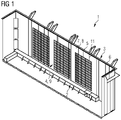
- Fig. 1 schematically presents an axonometric representation of an embodiment of a tank 1 according to the invention.
- This embodiment shows a transformer tank 1 comprising an internal space 2, a tank wall 3 surrounding the internal space 2, wherein the tank wall 3 comprises an inner side 4 facing towards the internal space 2, and a damping system.
- the damping system comprises a viscoelastic layer 5, which is located on the inner side 4 of the tank wall 3, and a metal sheet 6, which is located on the viscoelastic layer 5.
- the viscoelastic layer 5 is located behind the tank wall 3 and the metal sheet 6 is located behind the viscoelastic layer 5.
- a multitude of stud bolts 7 are welded to the inner side 4 of the tank wall 3. Both the viscoelastic layer 5 as well as the metal sheet 6 is attached to the inner side 4 of the tank wall 3, wherein the stud bolts 7 being placed in respective openings 8 in the viscoelastic layer 5 and in the metal sheet 6.
- the metal sheet 6 is welded to the stud bolts 7, wherein a contact pressure between the viscoelastic layer 5 and the inner side 4 of the tank wall 3 as well as between the metal sheet 6 and the viscoelastic layer 5 is between 0,3 N/mm 2 and 1 N/mm 2 .
- the metal sheet 6 has a planar surface 9 facing towards the internal space 2, wherein magnetic shunts 11 are attached to the surface 9.
- Fig. 2 schematically shows the metal sheet 6 which has a thickness T of at least 5 mm in this embodiment.
- the metal sheet 6 comprises several openings 8 to position and fix the metal sheet 6 on the stud bolts 7, wherein the openings preferably have a diameter of 20 mm.
- the maximum distance D1 between two adjacent openings 8 is 500 mm and the minimum distance D2 between an opening 8 and an edge of the metal sheet 6 is 50 mm.
- the viscoelastic layer 5 has the same dimensions and openings as the metal sheet 6, but the diameter of the openings 8 is slightly larger, preferably 25 mm.
- the tank wall 3 of the transformer is manufactured with a method according to the invention as follows: At the beginning, the stud bolts 7 are welded to the inner side 4 of the tank wall 3. The viscoelastic layer 5 and the metal sheet 6 are arranged on the stud bolts 7, whereby it would be conceivable that openings, pipes, reinforcement parts and other components that are arranged on the inner side 4 of the tank wall 3 are avoided.
- Fig. 3 schematically shows a sectional view of the tank wall 3 comprising the viscoelastic layer 5 and the metal sheet 6 before welding according to the invention.
- a nut 10 is mounted on each of the stud bolts 7, wherein each nut 10 is tightened with a torque of 75 Nm.
- Fig. 4 schematically shows a sectional view of the tank wall 3 comprising the viscoelastic layer 5, the metal sheet 6 and a nut 10 before welding according to the invention.
- each nut 10 comprises an opening, through which opening a spot welding is created for fixation of the viscoelastic layer 5 and the metal sheet 6.
- Fig. 5 schematically shows a corresponding sectional view of the tank wall 3 comprising the viscoelastic layer 5 and the metal sheet 6 after welding according to the invention.
- the tank wall 3 according to the invention reduces vibrations and noise due to the damping system on the inner side 4 of the tank wall 3.
Landscapes
- Engineering & Computer Science (AREA)
- General Engineering & Computer Science (AREA)
- Mechanical Engineering (AREA)
- Power Engineering (AREA)
- Physics & Mathematics (AREA)
- Acoustics & Sound (AREA)
- Multimedia (AREA)
- Chemical & Material Sciences (AREA)
- Combustion & Propulsion (AREA)
- Aviation & Aerospace Engineering (AREA)
- Regulation Of General Use Transformers (AREA)
Abstract
Description
- The present invention relates to a tank, particularly a transformer tank or a reactor tank, said tank comprising
- an internal space,
- at least one tank wall which surrounds the internal space preferably completely, wherein the at least one tank wall comprises an inner side facing towards the internal space, and
- a damping system.
- Furthermore, the present invention relates to a method for producing at least one damped tank wall of a tank, particularly a transformer tank or a reactor tank.
- Stationary induction devices such as transformers and reactors are commonly used in utility substations for electric power transmission.
- Transformers are passive electrical devices that transfer electrical energy between two or more circuits. A varying current in one coil of the transformer produces a varying magnetic flux, which, in turn, induces a varying electromotive force across a second coil wound around the same core. Electrical energy can be transferred between the two coils, without a metallic connection between the two circuits. Therefore, transformers are used for increasing or decreasing alternating voltages in electric power applications.
- Reactors are passive two-terminal electrical components that store energy in a magnetic field when electric current flows through them. Typically they consist of an insulated wire wound into a coil around a core.
- Both transformers and reactors in operation produce a low-frequency hum that is a source of noise pollution for persons working or living near the substations. The noise is mainly caused by vibration of the core and the coil as well as by vibration of the cooling device. These vibrations are being transmitted to the transformer tank or reactor tank, particularly to the tank wall, so that the tank vibrates and generates noise which is uniformly emitted to the surroundings.
- Hence, it is an objective of the present invention to reduce the vibrations as well as the noise of stationary induction devices in operation.
- In order to achieve the above-mentioned objective, in a tank, particularly a transformer tank or a reactor tank, said tank comprising
- an internal space,
- at least one tank wall which surrounds the internal space preferably completely, wherein the at least one tank wall comprises an inner side facing towards the internal space, and
- a damping system,
according to the present invention it is provided that the damping system comprises - at least one viscoelastic layer and
- at least one metal sheet, wherein
the damping system is arranged on the inner side of the at least one tank wall, so that the at least one viscoelastic layer is located behind the at least one tank wall and the at least one metal sheet is located behind the at least one viscoelastic layer seen in the direction from the at least one tank wall to the internal space. - For decreasing vibrations on the at least one tank wall as well as for attenuating the transmission of sound the damping system is placed inside the transformer tank on the inner side of the at least one tank wall.
- It would be conceivable that the damping system avoids openings, pipes, reinforcement parts and other components that are placed on the inner side of the at least one tank wall.
- The damping system comprises at least one viscoelastic layer which is arranged directly on the inner side of the at least one tank wall and at least one metal sheet which is arranged on the at least one viscoelastic layer. This means that, seen in the direction from the at least one wall to the internal space, the at least one viscoelastic layer is located behind the at least one tank wall and the at least one metal sheet is located behind the at least one viscoelastic layer. I.e. the at least one viscoelastic layer is sandwiched between the inner side of the at least one wall and the at least one metal plate.
- The at least one viscoelastic layer dissipates system energy due to the fact that it returns to its normal state more slowly than it is deformed.
- It would be conceivable that the at least one viscoelastic layer comprises polymers which allow a wide range of different compositions resulting in different material properties and behavior. Thus, the at least one viscoelastic layer can be developed and tailored efficiently for specific applications.
- In operation transformer and reactor tanks are filled with oil which has a temperature up to 80°C in average. Since the metal sheet is in direct contact with the oil and also transfers the heat to the at least one viscoelastic layer, both the at least one metal sheet and the at least one viscoelastic layer have to retain appropriate physical and chemical properties in the range of the temperature of the oil.
- In a preferred embodiment of the tank according to the present invention, it is provided that the thickness of the at least one viscoelastic layer is between 1 mm to 8 mm, preferably between 3 mm to 5 mm. Due to the very limited space available in the internal space of the tank, a thickness of the at least one viscoelastic layer in this range is the optimum for vibration and noise reduction.
- In addition, viscoelastic layers with a thickness between 1 mm to 8 mm, preferably between 3 mm to 5 mm, can be produced cost-effectively.
- Furthermore, a certain thickness is necessary for both the viscoelastic layer and the metal sheet, since both must withstand the operating temperatures of the transformer or reactor. Therefore, in a preferred embodiment of the tank according to the invention, it is provided that the thickness of the at least one metal sheet is at least 5 mm.
- Besides, a thickness of at least 5 mm is necessary to ensure that the metal sheet has a corresponding flash-over resistance.
- In a preferred embodiment of the tank according to the present invention, it is provided that at least two stud bolts are welded to the inner side of the at least one tank wall, wherein the at least one viscoelastic layer and the at least one metal sheet being attached to the inner side of the at least one tank wall by means of the at least two stud bolts. Such stud bolts are particularly simple and inexpensive to manufacture. Furthermore, they are resistant and withstand the stresses during operation of the transformer or the reactor.
- Welded joints between the at least two stud bolts and the inner side of the at least one tank wall ensure a secure connection and are characterized by particularly easy producibility. In addition, they can also withstand the high temperatures during operation.
- In a preferred embodiment of the tank according to the present invention, it is provided that the at least two stud bolts being placed in respective openings in the at least one viscoelastic layer and in the at least one metal sheet. I.e. the at least two stud bolts have a maximum distance which is smaller than a distance between two opposite edges of the metal sheet. This serves the simple arrangement of the at least one viscoelastic layer and the at least one metal sheet on the inner side of the at least one tank wall.
- In a preferred embodiment of the tank according to the present invention, it is provided that the at least one metal sheet is welded to the at least two stud bolts, wherein a contact pressure between the at least one viscoelastic layer and the inner side of the at least one tank wall as well as between the at least one metal sheet and the at least one viscoelastic layer is between 0,3 N/mm2 to 1 N/mm2, preferably between 0,4 N/mm2 to 0,6 N/mm2.
- In order to keep the desired performance - i.e. vibration and noise damping - the contact pressure between the at least one viscoelastic layer and the inner side of the at least one tank wall as well as between the at least one metal sheet and the at least one viscoelastic layer has to be between 0,3 N/mm2 to 1 N/mm2, preferably between 0,4 N/mm2 to 0,6 N/mm2.
- The welded joints between the at least two stud bolts and the at least one metal sheet ensure that the contact pressure is maintained during operation. Welded joints are characterized by special safety and by particularly easy producibility. In addition, they can also withstand the high temperatures during operation.
- In a preferred embodiment of the tank according to the present invention, it is provided that the maximum distance between the at least two stud bolts is 500 mm. This ensures a secure arrangement of the at least one viscoelastic layer and the at least one metal sheet on the inner side of the at least one tank wall.
- A maximum distance of 500 mm also ensures an even pressure distribution.
- In a preferred embodiment of the tank according to the present invention, it is provided that each of the at least two stud bolts has a minimum distance of 50 mm from an edge of the metal sheet. This distance ensures that the edges of the at least one metal sheet are not damaged by the welding process. This is of particular importance since damaged edges would no longer guarantee uniform pressure distribution.
- In a preferred embodiment of the tank according to the present invention, it is provided that the at least one metal sheet has a planar surface facing towards the internal space.
- A planar surface is advantageous, because it avoids a potential sparkover. Furthermore, there is no turbulence of the oil in the internal space.
- In addition, a planar surface allows for a balanced magnetic field as well as easier installation of magnetic shields (magnetic shunts).
- Accordingly, a transformer is provided, which includes a tank according to the invention.
- In a method for producing at least one damped tank wall of a tank, particularly a transformer tank or a reactor tank, which at least one tank wall surrounds an internal space preferably completely, wherein the at least one tank wall comprises an inner side facing towards the internal space, it is provided that the method includes the following steps:
- welding at least two stud bolts to the inner side of the at least one tank wall,
- placing at least one viscoelastic layer on the at least two stud bolts and on the inner side of the at least one tank wall,
- placing at least one metal sheet on the at least two stud bolts and on the at least one viscoelastic layer,
- applying a pressure on the at least one metal sheet so that a predefined contact pressure between the at least one viscoelastic layer and the inner side of the at least one tank wall as well as between the at least one metal sheet and the at least one viscoelastic layer is obtained,
- welding the at least one metal sheet to the at least two stud bolts, and
- cutting and grinding a surface of the at least one metal sheet facing towards the internal space so that the at least two remaining stud bolts are level with the at least one metal sheet and the at least one metal sheet has a planar surface.
- It would be conceivable that the welding processes are carried out by means of electric resistance welding.
- In a preferred embodiment of the method according to the present invention, it is provided that the contact pressure between the at least one viscoelastic layer and the inner side of the at least one tank wall as well as between the at least one metal sheet and the at least one viscoelastic layer is between 0,3 N/mm2 to 1 N/mm2, preferably between 0,4 N/mm2 to 0,6 N/mm2.
- In a preferred embodiment of the method according to the present invention, it is provided that the method comprises the following steps in order to apply the pressure on the at least one metal sheet:
- mounting a nut on each of the at least two stud bolts,
- tightening the nuts with a torque between 70 Nm to 80 Nm, preferably between 74 Nm to 76 Nm, and
- removing the nuts after welding of the at least one metal sheet to the at least two stud bolts.
- It would be conceivable that the nuts comprise an opening, through which opening the welding, preferably a spot welding, can be created for fixation of the at least one viscoelastic layer and the at least one metal sheet. This ensures that the contact pressure is maintained.
- The invention also comprises a tank obtainable by the method according to the invention.
- The invention will be explained in closer detail by reference to preferred embodiments. The drawings are, however, only exemplary and are not meant to restrict the scope of the invention as described above.
- Fig. 1
- schematically showing an axonometric representation of an embodiment of a tank according to the invention
- Fig. 2
- schematically showing a metal plate according to the invention
- Fig. 3
- schematically showing a sectional view of the tank wall comprising a viscoelastic layer and a metal sheet before welding according to the invention
- Fig. 4
- schematically showing a sectional view of the tank wall comprising the viscoelastic layer, the metal sheet and a nut before welding according to the invention
- Fig. 5
- schematically showing a sectional view of the tank wall comprising the viscoelastic layer and the metal sheet after welding according to the invention
-
Fig. 1 schematically presents an axonometric representation of an embodiment of a tank 1 according to the invention. This embodiment shows a transformer tank 1 comprising aninternal space 2, atank wall 3 surrounding theinternal space 2, wherein thetank wall 3 comprises an inner side 4 facing towards theinternal space 2, and a damping system. The damping system comprises aviscoelastic layer 5, which is located on the inner side 4 of thetank wall 3, and ametal sheet 6, which is located on theviscoelastic layer 5. This means that - seen in the direction from thetank wall 3 to the internal space 2 - theviscoelastic layer 5 is located behind thetank wall 3 and themetal sheet 6 is located behind theviscoelastic layer 5. - In this embodiment a multitude of
stud bolts 7 are welded to the inner side 4 of thetank wall 3. Both theviscoelastic layer 5 as well as themetal sheet 6 is attached to the inner side 4 of thetank wall 3, wherein thestud bolts 7 being placed inrespective openings 8 in theviscoelastic layer 5 and in themetal sheet 6. - The
metal sheet 6 is welded to thestud bolts 7, wherein a contact pressure between theviscoelastic layer 5 and the inner side 4 of thetank wall 3 as well as between themetal sheet 6 and theviscoelastic layer 5 is between 0,3 N/mm2 and 1 N/mm2. - The
metal sheet 6 has aplanar surface 9 facing towards theinternal space 2, whereinmagnetic shunts 11 are attached to thesurface 9. -
Fig. 2 schematically shows themetal sheet 6 which has a thickness T of at least 5 mm in this embodiment. Themetal sheet 6 comprisesseveral openings 8 to position and fix themetal sheet 6 on thestud bolts 7, wherein the openings preferably have a diameter of 20 mm. The maximum distance D1 between twoadjacent openings 8 is 500 mm and the minimum distance D2 between anopening 8 and an edge of themetal sheet 6 is 50 mm. - The
viscoelastic layer 5 has the same dimensions and openings as themetal sheet 6, but the diameter of theopenings 8 is slightly larger, preferably 25 mm. - The
tank wall 3 of the transformer is manufactured with a method according to the invention as follows:
At the beginning, thestud bolts 7 are welded to the inner side 4 of thetank wall 3. Theviscoelastic layer 5 and themetal sheet 6 are arranged on thestud bolts 7, whereby it would be conceivable that openings, pipes, reinforcement parts and other components that are arranged on the inner side 4 of thetank wall 3 are avoided.Fig. 3 schematically shows a sectional view of thetank wall 3 comprising theviscoelastic layer 5 and themetal sheet 6 before welding according to the invention. - Then, pressure is exerted on the
metal sheet 6 so that a defined contact pressure is created between themetal sheet 6 and theviscoelastic layer 5 and between theviscoelastic layer 5 and the inner side 4 of thetank wall 3. In order to create the corresponding pressure, anut 10 is mounted on each of thestud bolts 7, wherein eachnut 10 is tightened with a torque of 75 Nm.Fig. 4 schematically shows a sectional view of thetank wall 3 comprising theviscoelastic layer 5, themetal sheet 6 and anut 10 before welding according to the invention. - Then, the
metal sheet 6 is welded to thestud bolts 7 while the defined pressure is maintained via the nuts 10. For the welding process, eachnut 10 comprises an opening, through which opening a spot welding is created for fixation of theviscoelastic layer 5 and themetal sheet 6. - Finally, the nuts 10 are removed and the
stud bolts 7 and the corresponding weld seams are machined - i.e. cut and ground - so that themetal plate 6 has aplanar surface 9.Fig. 5 schematically shows a corresponding sectional view of thetank wall 3 comprising theviscoelastic layer 5 and themetal sheet 6 after welding according to the invention. - The
tank wall 3 according to the invention reduces vibrations and noise due to the damping system on the inner side 4 of thetank wall 3. -
- 1
- tank
- 2
- internal space
- 3
- tank wall
- 4
- inner side
- 5
- viscoelastic layer
- 6
- metal sheet
- 7
- stud bolt
- 8
- openings
- 9
- surface
- 10
- nut
- 11
- magnetic shunt
- D1
- maximum distance
- D2
- minimum distance
- T
- thickness
Claims (14)
- Tank (1), particularly a transformer tank or a reactor tank, said tank (1) comprising- an internal space (2),- at least one tank wall (3) which surrounds the internal space (2) preferably completely, wherein the at least one tank wall (3) comprises an inner side (4) facing towards the internal space (2), and- a damping system,
characterized in that
the damping system comprises- at least one viscoelastic layer (5) and- at least one metal sheet (6), wherein
the damping system is arranged on the inner side (4) of the at least one tank wall (3), so that the at least one viscoelastic layer (5) is located behind the at least one tank wall (3) and the at least one metal sheet (6) is located behind the at least one viscoelastic layer (5) seen in the direction from the at least one tank wall (3) to the internal space (2). - Tank (1) according to claim 1, characterized in that the thickness of the at least one viscoelastic layer (5) is between 1 mm to 8 mm, preferably between 3 mm to 5 mm.
- Tank (1) according to any of the claims 1 to 2, characterized in that the thickness (T) of the at least one metal sheet (6) is at least 5 mm.
- Tank (1) according to any of the claims 1 to 3, characterized in that at least two stud bolts (7) are welded to the inner side (4) of the at least one tank wall (3), wherein the at least one viscoelastic layer (5) and the at least one metal sheet (6) being attached to the inner side (4) of the at least one tank wall (3) by means of the at least two stud bolts (7).
- Tank (1) according to claim 4, characterized in that the at least two stud bolts (7) being placed in respective openings (8) in the at least one viscoelastic layer (5) and in the at least one metal sheet (6).
- Tank (1) according to any of the claims 4 to 5, characterized in that the at least one metal sheet (6) is welded to the at least two stud bolts (7), wherein a contact pressure between the at least one viscoelastic layer (5) and the inner side (4) of the at least one tank wall (3) as well as between the at least one metal sheet (6) and the at least one viscoelastic layer (5) is between 0,3 N/mm2 to 1 N/mm2, preferably between 0,4 N/mm2 to 0,6 N/mm2.
- Tank (1) according to any of the claims 4 to 6, characterized in that the maximum distance (D1) between the at least two stud bolts (7) is 500 mm.
- Tank (1) according to any of the claims 4 to 7, characterized in that each of the at least two stud bolts (7) has a minimum distance (D2) of 50 mm from an edge of the metal sheet (6).
- Tank (1) according to any of the claims 4 to 8, characterized in that the at least one metal sheet (6) has a planar surface (9) facing towards the internal space (2).
- Transformer or reactor comprising a tank (1) according to any of the claims 1 to 9.
- A method for producing at least one damped tank wall (3) of a tank (1), particularly a transformer tank or a reactor tank, which at least one tank wall (3) surrounds an internal space (2) preferably completely, wherein the at least one tank wall (3) comprises an inner side (4) facing towards the internal space (2), wherein the method includes the following steps:- welding at least two stud bolts (7) to the inner side (4) of the at least one tank wall (3),- placing at least one viscoelastic layer (5) on the at least two stud bolts (7) and on the inner side (4) of the at least one tank wall (3),- placing at least one metal sheet (6) on the at least two stud bolts (7) and on the at least one viscoelastic layer (5),- applying a pressure on the at least one metal sheet (6) so that a predefined contact pressure between the at least one viscoelastic layer (5) and the inner side (4) of the at least one tank wall (3) as well as between the at least one metal sheet (6) and the at least one viscoelastic layer (5) is obtained,- welding the at least one metal sheet (6) to the at least two stud bolts (7), and- cutting and grinding a surface (9) of the at least one metal sheet (6) facing towards the internal space (2) so that the at least two remaining stud bolts (7) are level with the at least one metal sheet (6) and the at least one metal sheet (6) has a planar surface (9).
- Method according to claim 11, characterized in that the contact pressure between the at least one viscoelastic layer (5) and the inner side (4) of the at least one tank wall (3) as well as between the at least one metal sheet (6) and the at least one viscoelastic layer (5) is between 0,3 N/mm2 to 1 N/mm2, preferably between 0,4 N/mm2 to 0,6 N/mm2.
- Method according to any of the claims 11 to 12, characterized in that the method comprises the following steps in order to apply the pressure on the at least one metal sheet (6):- mounting a nut (10) on each of the at least two stud bolts (7),- tightening the nuts (10) with a torque between 70 Nm to 80 Nm, preferably between 74 Nm to 76 Nm, and- removing the nuts (10) after welding of the at least one metal sheet (6) to the at least two stud bolts (7) .
- Tank (1) obtainable by a method according to any of the claims 11 to 13.
Priority Applications (1)
| Application Number | Priority Date | Filing Date | Title |
|---|---|---|---|
| EP20199995.0A EP3979275A1 (en) | 2020-10-05 | 2020-10-05 | Sound and vibration damping system for transformer tanks and reactor tanks |
Applications Claiming Priority (1)
| Application Number | Priority Date | Filing Date | Title |
|---|---|---|---|
| EP20199995.0A EP3979275A1 (en) | 2020-10-05 | 2020-10-05 | Sound and vibration damping system for transformer tanks and reactor tanks |
Publications (1)
| Publication Number | Publication Date |
|---|---|
| EP3979275A1 true EP3979275A1 (en) | 2022-04-06 |
Family
ID=72752294
Family Applications (1)
| Application Number | Title | Priority Date | Filing Date |
|---|---|---|---|
| EP20199995.0A Pending EP3979275A1 (en) | 2020-10-05 | 2020-10-05 | Sound and vibration damping system for transformer tanks and reactor tanks |
Country Status (1)
| Country | Link |
|---|---|
| EP (1) | EP3979275A1 (en) |
Citations (10)
| Publication number | Priority date | Publication date | Assignee | Title |
|---|---|---|---|---|
| US3102246A (en) * | 1958-12-17 | 1963-08-27 | Mc Graw Edison Co | Noise reducing means for transformer |
| JPS6397220U (en) * | 1986-12-15 | 1988-06-23 | ||
| US5579986A (en) * | 1993-10-29 | 1996-12-03 | Avdel Systems Limited | Dual-function fastener and method of use |
| JPH09106921A (en) * | 1995-10-12 | 1997-04-22 | Meidensha Corp | Noiseproof transformer |
| JP2000150262A (en) * | 1998-11-11 | 2000-05-30 | Daihen Corp | Magnetic shield type static induction electric equipment |
| US6177173B1 (en) * | 1998-07-01 | 2001-01-23 | 3M Innovative Properties Company | Damped laminates having welded through holes and/or edges with decreased spring back and improved fastener force retention and, a method of making |
| US20090031655A1 (en) * | 2004-05-21 | 2009-02-05 | Stephen John Kennedy | Structural sandwich plate members |
| DE102012012442A1 (en) * | 2012-06-22 | 2013-12-24 | Loos & Co. Kg | Sound-absorbing sandwich-like composite metal sheet for installation between core of oil-cooled transformer and transformer kettle walls, has plastic layer designed as shield against electromagnetic scattering fields in inner side of kettle |
| WO2017038459A1 (en) * | 2015-08-28 | 2017-03-09 | 株式会社明電舎 | Vibration control structure of stationary induction device |
| EP2856477B1 (en) * | 2012-06-05 | 2017-10-18 | Siemens Aktiengesellschaft | Tank for liquid-filled transformers or inductors |
-
2020
- 2020-10-05 EP EP20199995.0A patent/EP3979275A1/en active Pending
Patent Citations (10)
| Publication number | Priority date | Publication date | Assignee | Title |
|---|---|---|---|---|
| US3102246A (en) * | 1958-12-17 | 1963-08-27 | Mc Graw Edison Co | Noise reducing means for transformer |
| JPS6397220U (en) * | 1986-12-15 | 1988-06-23 | ||
| US5579986A (en) * | 1993-10-29 | 1996-12-03 | Avdel Systems Limited | Dual-function fastener and method of use |
| JPH09106921A (en) * | 1995-10-12 | 1997-04-22 | Meidensha Corp | Noiseproof transformer |
| US6177173B1 (en) * | 1998-07-01 | 2001-01-23 | 3M Innovative Properties Company | Damped laminates having welded through holes and/or edges with decreased spring back and improved fastener force retention and, a method of making |
| JP2000150262A (en) * | 1998-11-11 | 2000-05-30 | Daihen Corp | Magnetic shield type static induction electric equipment |
| US20090031655A1 (en) * | 2004-05-21 | 2009-02-05 | Stephen John Kennedy | Structural sandwich plate members |
| EP2856477B1 (en) * | 2012-06-05 | 2017-10-18 | Siemens Aktiengesellschaft | Tank for liquid-filled transformers or inductors |
| DE102012012442A1 (en) * | 2012-06-22 | 2013-12-24 | Loos & Co. Kg | Sound-absorbing sandwich-like composite metal sheet for installation between core of oil-cooled transformer and transformer kettle walls, has plastic layer designed as shield against electromagnetic scattering fields in inner side of kettle |
| WO2017038459A1 (en) * | 2015-08-28 | 2017-03-09 | 株式会社明電舎 | Vibration control structure of stationary induction device |
Similar Documents
| Publication | Publication Date | Title |
|---|---|---|
| KR101320170B1 (en) | Reactor | |
| US6531946B2 (en) | Low noise and low loss reactor | |
| EP3979275A1 (en) | Sound and vibration damping system for transformer tanks and reactor tanks | |
| JPH10116741A (en) | Magnetic shield for stationary induction device and method of mounting the same | |
| CN112383979B (en) | Medium-frequency heating device and method for special-shaped thick-wall end socket | |
| JP6191666B2 (en) | Vibration control structure of static induction equipment | |
| CN112769304B (en) | High-torque separation process for rotor core of stepping motor | |
| KR20110039786A (en) | Column transformer with cooling pipe | |
| CN110783069A (en) | Folder with circulating water cooling function and transformer thereof | |
| KR101768849B1 (en) | Oil type phase shift transformer in medium voltage inverter system | |
| KR200412228Y1 (en) | Soundproof structure inside transformer enclosure | |
| US20240055179A1 (en) | Power transformer having a noise reduction function | |
| JP7154397B2 (en) | Power converter for railway vehicles | |
| CN117524681A (en) | Resonant leakage inductance transformer for plate-type ozone generator | |
| KR102160183B1 (en) | Amorphous outdoor transformer and manufacturing method thereof | |
| JP3053322B2 (en) | Amorphous iron core transformer | |
| US20170110239A1 (en) | Acoustic Panels for Transformers | |
| CN221550750U (en) | An adjustable short-circuit device for transformer | |
| JPH07142268A (en) | High frequency induction heating transformer | |
| KR102684157B1 (en) | Transducer assembly with improved heating characteristics and electromagnetic shock wave therapy device using the same | |
| JPH0722257A (en) | Stationary induction | |
| CN1126421A (en) | Electromagnetic Shielding Device for AC Induction Motor Used in Railway | |
| CN223665278U (en) | A type of through-type current transformer | |
| Solanki | Transformer Noise | |
| JP2015023167A (en) | Stationary induction electric device |
Legal Events
| Date | Code | Title | Description |
|---|---|---|---|
| PUAI | Public reference made under article 153(3) epc to a published international application that has entered the european phase |
Free format text: ORIGINAL CODE: 0009012 |
|
| STAA | Information on the status of an ep patent application or granted ep patent |
Free format text: STATUS: THE APPLICATION HAS BEEN PUBLISHED |
|
| AK | Designated contracting states |
Kind code of ref document: A1 Designated state(s): AL AT BE BG CH CY CZ DE DK EE ES FI FR GB GR HR HU IE IS IT LI LT LU LV MC MK MT NL NO PL PT RO RS SE SI SK SM TR |
|
| STAA | Information on the status of an ep patent application or granted ep patent |
Free format text: STATUS: REQUEST FOR EXAMINATION WAS MADE |
|
| 17P | Request for examination filed |
Effective date: 20221004 |
|
| RBV | Designated contracting states (corrected) |
Designated state(s): AL AT BE BG CH CY CZ DE DK EE ES FI FR GB GR HR HU IE IS IT LI LT LU LV MC MK MT NL NO PL PT RO RS SE SI SK SM TR |
|
| RAP3 | Party data changed (applicant data changed or rights of an application transferred) |
Owner name: SIEMENS ENERGY GLOBAL GMBH & CO. KG |
|
| GRAP | Despatch of communication of intention to grant a patent |
Free format text: ORIGINAL CODE: EPIDOSNIGR1 |
|
| STAA | Information on the status of an ep patent application or granted ep patent |
Free format text: STATUS: GRANT OF PATENT IS INTENDED |