EP3979260B1 - Test system, and heating and temperature measuring device for simulating reactor pressure vessel heat exchange characteristics of nuclear power plant - Google Patents
Test system, and heating and temperature measuring device for simulating reactor pressure vessel heat exchange characteristics of nuclear power plant Download PDFInfo
- Publication number
- EP3979260B1 EP3979260B1 EP19957791.7A EP19957791A EP3979260B1 EP 3979260 B1 EP3979260 B1 EP 3979260B1 EP 19957791 A EP19957791 A EP 19957791A EP 3979260 B1 EP3979260 B1 EP 3979260B1
- Authority
- EP
- European Patent Office
- Prior art keywords
- heating
- simulator
- lower head
- temperature measuring
- measuring device
- Prior art date
- Legal status (The legal status is an assumption and is not a legal conclusion. Google has not performed a legal analysis and makes no representation as to the accuracy of the status listed.)
- Active
Links
Images


Classifications
-
- G—PHYSICS
- G21—NUCLEAR PHYSICS; NUCLEAR ENGINEERING
- G21C—NUCLEAR REACTORS
- G21C17/00—Monitoring; Testing ; Maintaining
- G21C17/001—Mechanical simulators
-
- G—PHYSICS
- G21—NUCLEAR PHYSICS; NUCLEAR ENGINEERING
- G21C—NUCLEAR REACTORS
- G21C17/00—Monitoring; Testing ; Maintaining
-
- G—PHYSICS
- G06—COMPUTING OR CALCULATING; COUNTING
- G06F—ELECTRIC DIGITAL DATA PROCESSING
- G06F30/00—Computer-aided design [CAD]
- G06F30/10—Geometric CAD
- G06F30/13—Architectural design, e.g. computer-aided architectural design [CAAD] related to design of buildings, bridges, landscapes, production plants or roads
-
- G—PHYSICS
- G06—COMPUTING OR CALCULATING; COUNTING
- G06F—ELECTRIC DIGITAL DATA PROCESSING
- G06F30/00—Computer-aided design [CAD]
- G06F30/20—Design optimisation, verification or simulation
-
- G—PHYSICS
- G21—NUCLEAR PHYSICS; NUCLEAR ENGINEERING
- G21C—NUCLEAR REACTORS
- G21C9/00—Emergency protection arrangements structurally associated with the reactor, e.g. safety valves provided with pressure equalisation devices
- G21C9/016—Core catchers
-
- G—PHYSICS
- G06—COMPUTING OR CALCULATING; COUNTING
- G06F—ELECTRIC DIGITAL DATA PROCESSING
- G06F2119/00—Details relating to the type or aim of the analysis or the optimisation
- G06F2119/08—Thermal analysis or thermal optimisation
-
- G—PHYSICS
- G21—NUCLEAR PHYSICS; NUCLEAR ENGINEERING
- G21C—NUCLEAR REACTORS
- G21C15/00—Cooling arrangements within the pressure vessel containing the core; Selection of specific coolants
- G21C15/18—Emergency cooling arrangements; Removing shut-down heat
-
- Y—GENERAL TAGGING OF NEW TECHNOLOGICAL DEVELOPMENTS; GENERAL TAGGING OF CROSS-SECTIONAL TECHNOLOGIES SPANNING OVER SEVERAL SECTIONS OF THE IPC; TECHNICAL SUBJECTS COVERED BY FORMER USPC CROSS-REFERENCE ART COLLECTIONS [XRACs] AND DIGESTS
- Y02—TECHNOLOGIES OR APPLICATIONS FOR MITIGATION OR ADAPTATION AGAINST CLIMATE CHANGE
- Y02E—REDUCTION OF GREENHOUSE GAS [GHG] EMISSIONS, RELATED TO ENERGY GENERATION, TRANSMISSION OR DISTRIBUTION
- Y02E30/00—Energy generation of nuclear origin
- Y02E30/30—Nuclear fission reactors
Definitions
- the present invention relates to the technical field of nuclear power, more particularly, to a test system, and a heating and temperature measuring device for simulating RPV heat exchange characteristics of a nuclear power plant.
- RPV reactor pressure vessel
- a reactor pit water injection system is designed in current nuclear power plant to inject water into the reactor pit to submergie the pit, such that the lower head of the RPV is cooled.
- the design and construction of the reactor pit water injection system in the prior art is obtained through one-dimensional and two-dimensional test and theoretical design.
- a test section in a prior art for processing a two-dimensional heating test consists of a copper heating section 1 and a stainless-steel flow channel 2.
- the copper heating section 1 is used to simulate a wall surface of the RPV heated by the core melt when an accident occurs
- the stainless-steel flow channel 2 is used to simulate a flow channel outside the lower head of the RPV
- a width of the copper heating section 1 is the same from the top to the bottom, and a heating rod and a thermocouple are inserted from a side surface and are arranged parallel to a heating surface.
- a technical problem to be solved in the present invention is to provide a heating and temperature measuring device for simulating PRV heat exchange characteristics when an accident occurs, and a test system for simulating RPV heat exchange characteristics of a nuclear power plant.
- a technical solution adopted by the present invention to solve the technical problem is to provide a heating and temperature measuring device for simulating RPV heat exchange characteristics when an accident occurs, wherein the heating and temperature measuring device includes a tube portion, a hemispherical lower head connected to a lower end of the tube portion, a heating assembly for heating the lower head, and a temperature measuring assembly disposed in the lower head; the temperature measuring assembly is configured to monitor a temperature change in a wall thickness direction of the lower head to monitor a surface temperature change of the lower head.
- An inner wall surface of the lower head is provided with a number of temperature measuring holes along a spherical center direction of the lower head.
- a number of heating holes are provided in the inner wall surface of the lower head along a spherical center direction of the lower head.
- the temperature measuring assembly includes a number of sets of thermocouples, and each set of thermocouple includes two thermocouples, and the thermocouple is inserted in the lower head perpendicular to an inner wall surface of the lower head.
- thermocouples are inserted in the temperature measuring holes one by one; depths of the two temperature measuring holes corresponding to each set of thermocouples are different.
- the depths of the two temperature measuring holes corresponding to each set of thermocouples are 102mm-107mm, 112 mm-117mm respectively.
- the lower head is provided with an annular recess on an inner wall surface adjacent to an opening side, and the lower head is separated into a non-heating section and a heating section respectively on an upper side and a lower side of the recess; the lower head is connected with the tube portion via the non-heating section, and the heating assembly and the temperature measuring assembly are disposed in the heating section.
- the heating and temperature measuring device further includes a sealing assembly disposed between the tube portion and the lower head;
- the sealing assembly includes a sealing flange, a high temperature resistant elastic gasket and a number of sets of locking members; a lower end surface of the tube portion is welded to an upper surface of the sealing flange; a lower surface of the sealing flange is provided with a convex annular step, an end surface of the opening side of the lower head is provided with an annular groove, the high temperature resistant elastic gasket is disposed in the annular groove, and the annular step is tightly abutted against the high temperature resistant elastic gasket and fits within the annular groove; the locking members extends through the sealing flange and the non-heating section of the lower head.
- a number of first locking holes are provided in the sealing flange spaced along a circumference direction of the sealing flange and extending through an upper surface and a lower surface thereof, the non-heating section of the lower head is provided with a number of second locking holes spaced along a circumference direction of the lower head and communicated with the first locking holes correspondingly, and the second locking hole extends downward to be communicated with the recess from the end surface of the opening side of the lower head.
- the annular groove is located outside the second locking hole.
- the tube portion is a stainless-steel tube
- the lower head is a hemispherical copper shell.
- the cooling tank simulator includes an annular tank body and a first heat exchanger, a liquid level of the tank body is kept below the exhaust outlet, and the first heat exchanger is disposed in the tank body and below the liquid level thereof.
- the cooling tank simulator further includes a spray mechanism and/or a second heat exchanger disposed in the tank body and located above the exhaust outlet.
- a pit wall of the pit simulator is provided with at least one water inlet communicated with the water injection space for accessing the cooling water.
- the pit simulator, the RPV simulator, the insulation layer simulator and the cooling tank simulator are arranged in a ratio of 1:5 to sizes of the corresponding prototypes respectively.
- the test system further includes a water return line disposed outside the pit simulator; an upper end of the water return line is communicated with the cooling tank simulator, and a lower end of the water return line is communicated with the water injection space.
- the present invention has the following beneficial effects: the present invention is configured to simulate a process that a high temperature core melt is transferred to a wall surface of the RPV(reactor pressure vessel) and flows outside the wall surface of the RPV under a severe accident condition of a nuclear power plant, so that to study the distribution of CHF(critical heat flux) and three-dimensional cooling water flow characteristics at different positions on an outer wall surface of the RPV under a three-dimensional flow condition, thereby providing data support for studying the effectiveness of a severe accident mitigation system -a pit water injection system.
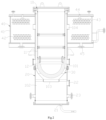
- a test system for simulating RPV heat exchange characteristics of a nuclear power plant in an embodiment of the present invention includes a heating and temperature measuring device 10, a pit simulator 20, an insulation layer simulator 30, and a cooling tank simulator 40.
- the heating and temperature measuring device 10 serves as a RPV simulator and is suspended in the pit simulator 20.
- the insulation layer simulator 30 is provided on an outer periphery of the RPV simulator.
- the cooling tank simulator 40 is disposed on an outer periphery of an upper end of the RPV simulator.
- a cooling water flow channel 101 is defined between the insulation layer simulator 30 and the RPV simulator (the heating and temperature measuring device 10), and a water injection space 102 is defined between the insulation layer simulator 30 and an inner wall surface of the pit simulator 20.
- a water inlet 103 is provided at a bottom of the insulation layer simulator 30 and communicates the cooling water flow channel 101 with the water injection space 102, so that the cooling water in the water injection space 102 is able to enter the cooling water flow channel 101 through the water inlet 103.
- An upper end of the insulation layer simulator 30 is provided with an exhaust outlet 104 communicated with the cooling water flow channel 101.
- the cooling water in the cooling water flow channel 101 is heated outside the RPV simulator to form a steam-water two-phase flow, and the steam-water two-phase flow flows upward along the cooling water flow channel 101 and then is separated to steam and water when flowing through the exhaust outlet 104, and the liquid water falls into the cooling tank simulator 40.
- the pit simulator 20, the RPV simulator (the heating and temperature measuring device 10), the insulation layer simulator 30 and the cooling tank simulator 40 are respectively arranged in a ratio of 1:5 to the corresponding prototypes.
- the heating assembly may be disposed in the lower head 12, and may include a number of heating rods to heat the lower head 12.
- the heating rods are inserted into the lower head 12 vertical to an inner wall surface of the lower head 12.
- the high temperature resistant elastic gasket 132 is disposed in the annular groove 124, and the annular step 134 is tightly abutted against the high temperature resistant elastic gasket 132 and fits within the annular groove 124, to realize a concace-convex sealing fit between the sealing flange 131 and the lower head 12.
- a number of sets of the locking members 133 are spaced distributed along a circumference direction of the sealing flange 131.
- Each set of locking member 133 extends through the sealing flange 131 and the non-heating section 121 of the lower head 12, to firmly lock the sealing flange 131 with the lower head 12, thereby to firmly lock the tube portion 11 with the lower head 12.
- the locking member 133 may include a bolt and at least one nut mating therewith.
- the two temperature measuring holes 126 corresponding to each set of thermocouples are arranged in a center position of a region surrounded by four heating holes 120, so that each set of thermocouples is located in a center position of a region surrounded by four heating rods.
- the area enclosed by four heating rods has the largest space, thus to facilitate the arrangement and insertion of the thermocouples, and the four heating rods are of the same power.
- the test system of the present invention can simulate a whole process of a pit water injection of a nuclear power plant when a severe accident occurs, mainly simulate a process and a flow direction of the cooling water when being injected into the pit and then being heated in the channel outside the lower head of the RPV and the insulation layer of the RPV to form steam-water two-phase flow, and obtain the heat flux of the lower head by real time monitor, thereby the heating characteristics of different regions of a wall surface of the RPV and the two-phase flow characteristics of an outer wall surface of the lower head of the RPV can be studied. Meanwhile, a test, such as a CHF experiment under natural cycle and forced cycle conditions, or a temperature response test under false water injection condition or the like, can be conducted.
Landscapes
- Engineering & Computer Science (AREA)
- Physics & Mathematics (AREA)
- General Engineering & Computer Science (AREA)
- Geometry (AREA)
- Theoretical Computer Science (AREA)
- General Physics & Mathematics (AREA)
- Computer Hardware Design (AREA)
- Plasma & Fusion (AREA)
- High Energy & Nuclear Physics (AREA)
- Evolutionary Computation (AREA)
- Structural Engineering (AREA)
- Computational Mathematics (AREA)
- Mathematical Analysis (AREA)
- Mathematical Optimization (AREA)
- Pure & Applied Mathematics (AREA)
- Civil Engineering (AREA)
- Architecture (AREA)
- Monitoring And Testing Of Nuclear Reactors (AREA)
Description
- The present invention relates to the technical field of nuclear power, more particularly, to a test system, and a heating and temperature measuring device for simulating RPV heat exchange characteristics of a nuclear power plant.
- When a severe accident occurs in a nuclear power plant, a core is exposed and finally melt due to a coolant loss of a primary loop system of the nuclear power plant, and the core corium will eventually collapse into the lower head of RPV (reactor pressure vessel). If the core corium cannot be cooled in time, the corium will eventually melt through the lower head of the RPV because of the core decay heat, thus the core melt falls in the reactor pit and may possibly melt through a bottom plate of a containment, resulting in a large leakage of radioactive substance in the end.
- To solve the problems above, a reactor pit water injection system is designed in current nuclear power plant to inject water into the reactor pit to submergie the pit, such that the lower head of the RPV is cooled. The design and construction of the reactor pit water injection system in the prior art is obtained through one-dimensional and two-dimensional test and theoretical design.
- As shown in
Fig. 1 , a test section in a prior art for processing a two-dimensional heating test consists of acopper heating section 1 and a stainless-steel flow channel 2. Thecopper heating section 1 is used to simulate a wall surface of the RPV heated by the core melt when an accident occurs, and the stainless-steel flow channel 2 is used to simulate a flow channel outside the lower head of the RPV A width of thecopper heating section 1 is the same from the top to the bottom, and a heating rod and a thermocouple are inserted from a side surface and are arranged parallel to a heating surface. During the test, all cooling water entering theflow channel 2 of the test section from an inlet at a bottom of the test section can only flow in one direction from the bottom to the top of the test section in the narrow flow channel, so that the three-dimensional flow state of an outer wall surface of the lower head of the RPV under a real condition cannot be simulated, thereby a great difference is existed with the actual flow condition. - Examples of devices for simulating the heat flux of a nuclear reactor are described in the
applications CN 103 594 133 B ,CN 106 251 919 A andKR 2010 0125147 A - A technical problem to be solved in the present invention is to provide a heating and temperature measuring device for simulating PRV heat exchange characteristics when an accident occurs, and a test system for simulating RPV heat exchange characteristics of a nuclear power plant.
- A technical solution adopted by the present invention to solve the technical problem is to provide a heating and temperature measuring device for simulating RPV heat exchange characteristics when an accident occurs, wherein the heating and temperature measuring device includes a tube portion, a hemispherical lower head connected to a lower end of the tube portion, a heating assembly for heating the lower head, and a temperature measuring assembly disposed in the lower head;
the temperature measuring assembly is configured to monitor a temperature change in a wall thickness direction of the lower head to monitor a surface temperature change of the lower head. An inner wall surface of the lower head is provided with a number of temperature measuring holes along a spherical center direction of the lower head. Corresponding to the heating assembly, a number of heating holes are provided in the inner wall surface of the lower head along a spherical center direction of the lower head. - Preferably, the temperature measuring assembly includes a number of sets of thermocouples, and each set of thermocouple includes two thermocouples, and the thermocouple is inserted in the lower head perpendicular to an inner wall surface of the lower head.
- Preferably, the thermocouples are inserted in the temperature measuring holes one by one; depths of the two temperature measuring holes corresponding to each set of thermocouples are different.
- Preferably, the depths of the two temperature measuring holes corresponding to each set of thermocouples are 102mm-107mm, 112 mm-117mm respectively.
- Preferably, the lower head is provided with an annular recess on an inner wall surface adjacent to an opening side, and the lower head is separated into a non-heating section and a heating section respectively on an upper side and a lower side of the recess; the lower head is connected with the tube portion via the non-heating section, and the heating assembly and the temperature measuring assembly are disposed in the heating section.
- Preferably, the heating and temperature measuring device further includes a sealing assembly disposed between the tube portion and the lower head; the sealing assembly includes a sealing flange, a high temperature resistant elastic gasket and a number of sets of locking members;
a lower end surface of the tube portion is welded to an upper surface of the sealing flange; a lower surface of the sealing flange is provided with a convex annular step, an end surface of the opening side of the lower head is provided with an annular groove, the high temperature resistant elastic gasket is disposed in the annular groove, and the annular step is tightly abutted against the high temperature resistant elastic gasket and fits within the annular groove; the locking members extends through the sealing flange and the non-heating section of the lower head. - Preferably, a number of first locking holes are provided in the sealing flange spaced along a circumference direction of the sealing flange and extending through an upper surface and a lower surface thereof, the non-heating section of the lower head is provided with a number of second locking holes spaced along a circumference direction of the lower head and communicated with the first locking holes correspondingly, and the second locking hole extends downward to be communicated with the recess from the end surface of the opening side of the lower head.
- Preferably, the annular groove is located outside the second locking hole.
- Preferably, the high temperature resistant elastic gasket is a graphite gasket.
- Preferably, the tube portion is a stainless-steel tube, and the lower head is a hemispherical copper shell.
- The present invention further provides a test system for simulating RPV heat exchange characteristics of a nuclear power plant, including the heating and temperature measuring device, a pit simulator, an insulation layer simulator and a cooling tank simulator; wherein the heating and temperature measuring device is configured as a RPV simulator and is suspended in the pit simulator, the insulation layer simulator is disposed on an outer periphery of the RPV simulator, and the cooling tank simulator is disposed on an outer periphery of an upper end of the RPV simulator;
a cooling water flow channel is defined between the insulation layer simulator and the RPV simulator, and a water injection space is defined between the insulation layer simulator and an inner wall surface of the pit simulator; a water inlet communicating the cooling water flow channel with the water injection space is provided at a bottom of the insulation layer simulator, so that cooling water in the water injection space is able to enter the cooling water flow channel through the water inlet, and the cooling water is heated outside the lower head of the RPV simulator to generate a steam-water two-phase flow; an upper end of the insulation layer simulator is provided with an exhaust outlet communicated with the cooling water flow channel, the steam-water two-phase flow flows upward along the cooling water flow channel and then is separated to steam and water when flowing through the exhaust outlet, and the liquid water falls into the cooling tank simulator. - Preferably, the cooling tank simulator includes an annular tank body and a first heat exchanger, a liquid level of the tank body is kept below the exhaust outlet, and the first heat exchanger is disposed in the tank body and below the liquid level thereof.
- Preferably, the cooling tank simulator further includes a spray mechanism and/or a second heat exchanger disposed in the tank body and located above the exhaust outlet.
- Preferably, a pit wall of the pit simulator is provided with at least one water inlet communicated with the water injection space for accessing the cooling water.
- Preferably, the pit simulator, the RPV simulator, the insulation layer simulator and the cooling tank simulator are arranged in a ratio of 1:5 to sizes of the corresponding prototypes respectively.
- Preferably, the test system further includes a water return line disposed outside the pit simulator; an upper end of the water return line is communicated with the cooling tank simulator, and a lower end of the water return line is communicated with the water injection space.
- The present invention has the following beneficial effects: the present invention is configured to simulate a process that a high temperature core melt is transferred to a wall surface of the RPV(reactor pressure vessel) and flows outside the wall surface of the RPV under a severe accident condition of a nuclear power plant, so that to study the distribution of CHF(critical heat flux) and three-dimensional cooling water flow characteristics at different positions on an outer wall surface of the RPV under a three-dimensional flow condition, thereby providing data support for studying the effectiveness of a severe accident mitigation system -a pit water injection system.
- The present invention will now be further described with reference to the accompanying drawings and embodiments, and in the drawings:
-
Fig. 1 is a schematic structural view of a test section of a two-dimensional heating test in a prior art; -
Fig. 2 is a cross-sectional view of a test system according to an embodiment of the present invention; -
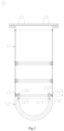
Fig. 3 is a cross-sectional view of a heating and temperature measuring device of the test system inFig. 2 ; -
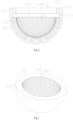
Fig. 4 is a cross-sectional view of a lower head of the heating and temperature measuring device inFig. 3 ; -
Fig. 5 is a schematic view of a heating section of the lower head inFig. 4 ; -
Fig. 6 is an enlarged schematic view of part A of the heating and temperature measuring device inFig. 4 ; and -
Fig. 7 is a partial cross-sectional view of the heating section of the lower head inFig. 5 . - To clearly understand the technical features, objectives and effects of the invention, specific embodiments of the invention will now be described in detail with reference to the accompanying drawings.
- As shown in
Fig. 2 , a test system for simulating RPV heat exchange characteristics of a nuclear power plant in an embodiment of the present invention includes a heating andtemperature measuring device 10, apit simulator 20, aninsulation layer simulator 30, and acooling tank simulator 40. The heating andtemperature measuring device 10 serves as a RPV simulator and is suspended in thepit simulator 20. Theinsulation layer simulator 30 is provided on an outer periphery of the RPV simulator. Thecooling tank simulator 40 is disposed on an outer periphery of an upper end of the RPV simulator. - A cooling
water flow channel 101 is defined between theinsulation layer simulator 30 and the RPV simulator (the heating and temperature measuring device 10), and awater injection space 102 is defined between theinsulation layer simulator 30 and an inner wall surface of thepit simulator 20. Awater inlet 103 is provided at a bottom of theinsulation layer simulator 30 and communicates the coolingwater flow channel 101 with thewater injection space 102, so that the cooling water in thewater injection space 102 is able to enter the coolingwater flow channel 101 through thewater inlet 103. An upper end of theinsulation layer simulator 30 is provided with anexhaust outlet 104 communicated with the coolingwater flow channel 101. The cooling water in the coolingwater flow channel 101 is heated outside the RPV simulator to form a steam-water two-phase flow, and the steam-water two-phase flow flows upward along the coolingwater flow channel 101 and then is separated to steam and water when flowing through theexhaust outlet 104, and the liquid water falls into thecooling tank simulator 40. - As an embodiment, the
pit simulator 20, the RPV simulator (the heating and temperature measuring device 10), theinsulation layer simulator 30 and thecooling tank simulator 40 are respectively arranged in a ratio of 1:5 to the corresponding prototypes. - Wherein, the heating and
temperature measuring device 10 serves as the RPV simulator and is configured to simulate heat exchange characteristics of the reactor pressure vessel (RPV) under an accident. As shown inFig. 2 andFig. 3 , the heating andtemperature measuring device 10 includes atube portion 11, a hemisphericallower head 12, a heating assembly (not shown in the drawings) and a temperature measuring assembly. Thetube portion 11 is a non-heating portion, and an upper end thereof is enclosed by an end cover, etc. Thelower head 12 is connected to a lower end of thetube portion 11 to enclose the lower end of thetube portion 11. The heating assembly heats thelower head 12, enabling a three-dimensional heating section formed on thelower head 12, thereby a heat transfer of the lower head of the RPV and a three-dimensional flow characteristics of an outer wall surface of the RPV can be completely simulated when a serious accident occurs. The temperature measuring assembly is disposed in thelower head 12, and is configured to monitor a temperature change in a wall thickness direction of thelower head 12 to monitor a surface temperature change of thelower head 12. Thereby, a real-time temperature measuring, a real-time monitor of a heating state and a stable measurement of a heat flux of different regions within aheating section 122 are realized, and the disturbance of a heating rod to the temperature measuring is avoided. - The cooling water in the cooling
water flow channel 101 is generally heated outside thelower head 12 to generate a steam-water two-phase flow. The cooling water can flow in any direction outside a spherical surface of thelower head 12, thus a three-dimensional flow state of an outer wall surface of the lower head of the RPV is able to be simulated under a real condition, which is more consistent with the actual flow situation. - Specifically, the
tube portion 11 may be formed by two or more axial sections sequentially connected in an axial direction, thereby facilitating providing sufficient space for installing the heating assembly and arranging wires and the like, and realizing the operability for an operator. - Alternatively, in the heating and
temperature measuring device 10, thetube portion 11 may be a stainless-steel tube, and thelower head 12 may be a hemispherical copper shell. - The heating assembly may be disposed in the
lower head 12, and may include a number of heating rods to heat thelower head 12. The heating rods are inserted into thelower head 12 vertical to an inner wall surface of thelower head 12. By a uniform arrangement of a plurality of (eg. hundreds of, or thousands of) the heating rods in thelower head 12, regional fine heating can be achieved with a maximum heating heat flux of 2.0MW/m2. - As shown in
Figs. 3 to 5 , corresponding to the heating assembly, a number ofheating holes 120 are uniformly provided in an inner wall surface of thelower head 12 along a spherical center direction of thelower head 12. Theheating hole 120 is a blind hole not extending through an outer wall surface of thelower head 12. Each heating rod is inserted into acorresponding heating hole 120. - Since the
heating hole 120 into which the heating rod is inserted is a blind hole, the processing and installation error of the heating rod and theheating hole 120 needs to be strictly controlled, to prevent the heating rod from being pushed out by remaining air in the blind hole when heating, and to ensure sufficient contact between the heating rod and an inner wall surface of theheating hole 120 when being expanded. By controlling a distance between the heating rod and theheating hole 120, the influence of the blind hole on ejection of the heating rod when being heated is achieved, and the heating expansion fitness is achieved, and the burnout possibility of the heating rod is effectively reduced. - Furthermore, in the heating and
temperature measuring device 10, thelower head 12 is connected to the lower end of thetube portion 11 in a sealing mode. During a test process, thelower head 12 and thetube portion 11 are submerged in water, and a large number of heating rods are installed in thelower head 12. During the test operation, a body of thelower head 12 has a great temperature gradient and a sealing surface being deformed, thus a good sealing of a contact surface between thelower head 12 and thetube portion 11 is required, to prevent leakage of the contact surface from damaging the device. - To achieve a sealed connection between the
lower head 12 and thetube portion 11, the heating andtemperature measuring device 10 further includes a sealingassembly 13 disposed between thetube portion 11 and thelower head 12. To reduce the deformation of the sealing surface caused by the transmission of the heat generated by the heating assembly to the sealing assembly, thelower head 12 may include anon-heating section 121 and aheating section 122. Thenon-heating section 121 is located adjacent to and configured for being matched with the sealingassembly 13, and theheating section 122 is configured for installing the heating assembly therein. Theheating hole 120 is defined in theheating section 122. - A thickness of the
heating section 122 of thelower head 12 is determined by a length of the heating rod, a heating capacity, the number of the heating holes 120 and a required space of the heating holes 120. If the wall thickness of theheating section 122 is larger, then the length of the heating rod is larger, and the inner space of theheating section 122 is less, thus there is no enough space for drilling a larger number of the heating holes 120. If the wall thickness of theheating section 122 is smaller, then there is enough space inside theheating section 122 for drilling, but the heating capacity and the surface heating power of the heating rod have higher requirement since the length of the heating rod is smaller. Therefore, factors such as the heating design capacity of the heating rods and the number of the heating rods etc. should be fully considered in selecting the wall thickness of theheating section 122. The relationship of the thickness of thelower head 12 and the depth and the quantity of theheating hole 120 are mutual coupling: 1) when a radius of thelower head 12 is defined, the thickness of thelower head 12 determines the depth of theheating hole 120, and the installation spaces and amounts of the heating holes 120 and heating rod wires; 2) a diameter and a heating length of the heating rod are determined by a power, a heating section and a manufacturing process of the heating rod. The thickness of thelower head 12 and the depth and the quantity of theheating hole 120 can be determined by considering the above factors overall. - In the present embodiment, the wall thickness of the lower head 12 (the wall thickness of the heating section 122) is 100mm-120mm. The
heating hole 120 has a depth of 85mm-100mm with a tolerance of ± 0.1mm, an inner diameter of 10mm-15mm with a tolerance of -0.00mm to +0.02mm, and a perpendicularity of 0.01mm. The inner wall surface of theheating hole 120 should be smooth, scratch free and has a roughness of <Ra1.6. Correspondingly, the heating rod has a total length of ≤ 120mm, a heating length of 80mm-90mm, and an outer diameter of 10mm-15mm with a tolerance of -0mm to +0.4mm. A rated power of the heating rod can be selected at ~1.8kW. - Specifically, the
lower head 12 is provided with anannular recess 123 on an inner wall surface adjacent to an opening side thereof, and the lower head is separated by therecess 123 into thenon-heating section 121 and theheating section 122 respectively on an upper side and a lower side of therecess 123. Thelower head 12 is connected with thetube portion 11 via thenon-heating section 121, and the heating assembly is disposed in theheating section 122. Theheating section 122 occupies a large volume of thelower head 12 and is a hemispherical three-dimensional section. Thenon-heating section 121 and theheating section 122 are connected by a side wall thinned by therecess 123, thereby reducing a contact area between thenon-heating section 121 and theheating section 122. Thenon-heating section 121 acts as an isolation function and provides conditions for the installation of the sealingassembly 13 at the same time. - In the
heating section 122 of thelower head 12, a number of the heating rods are evenly spaced and inserted into the corresponding heating holes 120. Theheating section 122 may further include a number of heating units, and each heating unit has a plurality of the heating rods therein. To facilitate a power control of each heating unit, the heating rods of different heating units may be connected to different power controllers according to the actual requirements. For example, the powers of the heating rods of the adjacent heating units are different, and by performing heating power controls of different units, to control the temperatures of different units in theentire heating section 122. - As shown in
Fig. 3 andFig. 4 , the sealingassembly 13 includes a sealingflange 131, a high temperature resistantelastic gasket 132 and a number of sets of lockingmembers 133. The sealingflange 131 fits between thetube portion 11 and thelower head 12, and a lower end surface of thetube portion 11 is welded to an upper surface of the sealingflange 131. A lower surface of the sealingflange 131 cooperates with an end surface of the opening side of thelower head 12. Specifically, the lower surface of the sealingflange 131 is provided with a convexannular step 134, and the end surface of the opening side of thelower head 12 is provided with anannular groove 124. The high temperature resistantelastic gasket 132 is disposed in theannular groove 124, and theannular step 134 is tightly abutted against the high temperature resistantelastic gasket 132 and fits within theannular groove 124, to realize a concace-convex sealing fit between the sealingflange 131 and thelower head 12. - Preferably, in the present embodiment, the high temperature resistant
elastic gasket 132 is a graphite gasket. - A number of sets of the locking
members 133 are spaced distributed along a circumference direction of the sealingflange 131. Each set of lockingmember 133 extends through the sealingflange 131 and thenon-heating section 121 of thelower head 12, to firmly lock the sealingflange 131 with thelower head 12, thereby to firmly lock thetube portion 11 with thelower head 12. The lockingmember 133 may include a bolt and at least one nut mating therewith. - Corresponding to the locking
member 133, a number of first locking holes 135 are provided in the sealingflange 131 spaced along the circumference direction of the sealingflange 131 and extending through an upper surface and a lower surface thereof. Thenon-heating section 121 of thelower head 12 is provided with a number of second locking holes 125 spaced along the circumference direction of thelower head 12, and thesecond locking hole 125 is communicated with thefirst locking hole 135 correspondingly. - Wherein, the
first locking hole 135 is located inside theannular step 134 along a radial direction of the sealingflange 131. Correspondingly, thesecond locking hole 125 is inside theannular groove 124 along a radial direction of thelower head 12. Otherwise, theannular groove 124 is located outside thesecond locking hole 125. - Particularly, the
second locking hole 125 extends downward to be communicated with therecess 123 from the end surface of the opening side of thelower head 12, forming a shape of through hole. Thesecond locking hole 125, of a through hole shape, enables a lower end of the bolt of the lockingmember 133 to extend into therecess 123, thereby a nut can be screwed with the lower end of the bolt, combined with a nut assembled on an upper end of the bolt, to form a double head locking. It provides a better bolt fastening than in a blind hole, and improves the fastening between the sealingflange 131 and thelower head 12. - Furthermore, since the
heating section 122 of thelower head 12 is located below therecess 123, therecess 123 is able to reduce the heat transfer of theheating section 122 to a flange surface, thereby to decrease the expansion degree of the sealingflange 131, and to ensure the connection sealing performance. - The temperature measuring assembly may include a number of sets of thermocouples, and each set of thermocouple includes two thermocouples. The thermocouples are inserted in the
lower head 12 perpendicular to an inner wall surface of thelower head 12. Specifically, the thermocouple is inserted in theheating section 122 of thelower head 12. - Corresponding to the temperature measuring assembly, an inner wall surface of the
lower head 12 is provided with a number oftemperature measuring holes 126 along a spherical center direction of thelower head 12, and each thermocouple is inserted into a correspondingtemperature measuring hole 126. Corresponding to two thermocouples being configured as one set, every twotemperature measuring holes 126 are also configured as one set, and are arranged corresponding to the two thermocouples of each set of thermocouples. Depths of the twotemperature measuring holes 126 corresponding to each set of thermocouples are different, so that insertion depths of the two thermocouples of each set of thermocouples are different and serve as a set of temperature measuring points. - In the present embodiment, corresponding to the wall thickness of the
lower head 12, the depths of the twotemperature measuring holes 126 corresponding to each set of thermocouples may be 102mm-107mm, 112 mm-117mm respectively. - As shown in
Figs. 4-6 , in the present embodiment, the twotemperature measuring holes 126 corresponding to each set of thermocouples are arranged in a center position of a region surrounded by fourheating holes 120, so that each set of thermocouples is located in a center position of a region surrounded by four heating rods. In thelower head 12, the area enclosed by four heating rods has the largest space, thus to facilitate the arrangement and insertion of the thermocouples, and the four heating rods are of the same power. - The two thermocouples of each set of thermocouples are arranged along the spherical center direction with the same tilt angle.
- As shown in
Fig. 7 , by the insertion of the plurality of heating rods in the corresponding heating holes 120 and the uniform arrangement of the plurality of heating rods in thelower head 12, theheating section 122 of thelower head 12 can be divided into a plurality of equal temperature distribution regions 127 (the regions defined by dashed lines inFig. 7 ) along the spherical center direction. In thelower head 12, the temperature measuring points of the twothermocouples 128 are arranged in the equaltemperature distribution region 127, and the depths of the temperature measuring holes corresponding to the twothermocouples 128 are different. - During the test, a thermal flow density qi of the equal
temperature distribution region 127 is obtained by Fourier formula:

- In the above formula, qi is the thermal flow density of the equal
temperature distribution region 127, in W/m2; ti is a measured value of the thermocouple with a smaller depth of one set of thermocouples, and t0 is a measured value of the thermocouple with a larger depth of one set of thermocouples;λ is a thermal conductivity (integral average) of a copper; and △l is a depth difference of the two thermocouples in one set of thermocouples, in mm. - Wherein
λ is obtained by the following formula:

- Furthermore, as shown in
Fig. 2 , in the test system, thecooling tank simulator 40 includes anannular tank body 41 disposed at an outer periphery of an upper end of the heating andtemperature measuring device 10 and afirst heat exchanger 42 disposed in thetank body 41. - The
exhaust outlet 104 is communicated with an inner space of thetank body 41, and the liquid level of thetank body 41 is kept below theexhaust outlet 104 to keep theexhaust outlet 104 clear during the test. Thefirst heat exchanger 42 is disposed below the liquid level in thetank body 41. Thefirst heat exchanger 42 may include a plurality of cooling tubes for the cooling water flowing and heat exchanging with the water in thetank body 41. The cooling tube may be annularly arround the outer periphery of the upper end of the heating andtemperature measuring device 10. - The
cooling tank simulator 40 further includes aspray mechanism 44 and / or asecond heat exchanger 43 disposed in thetank body 41 and located above theexhaust outlet 104, and is configured for cooling the vapor discharged from theexhaust outlet 104, so that the vapor condenses into liquid and falls into thetank body 41. Thesecond heat exchanger 43 may be arranged with reference to thefirst heat exchanger 42. - A pit wall of the
pit simulator 20 may be provided with at least one water inlet (not shown in the drawings) communicated with thewater injection space 102 for accessing cooling water. During the test, the cooling water is fed into thewater injection space 102 through the water inlet. When the test is finished, the water inlet may act as a water outlet to drain off water, or awater outlet 21 can be provided at a bottom of thepit simulator 20 to drain off water. Of course, the cooling water may alternatively be fed into thetank body 41 through thespray mechanism 44 of thecooling tank simulator 40 or a interface of thetank body 41, and then the cooling water flows into thewater injection space 102. - To facilitate observing the inner condition of the
pit simulator 20 during the test, at least one observingwindow 22 may be provided on a pit wall of thepit simulator 20. Observing window may also be provided on a wall surface of thetank body 41 of thecooling tank simulator 40. - Furthermore, the test system of the invention further includes a water return line (not shown in the drawings) disposed outside the
pit simulator 20. An upper end of the water return line is communicated with thecooling tank simulator 40, and a lower end of the water return line is communicated with thewater injection space 102. Corresponding to the water return line, afirst interface 45 is provided at a lower end of thetank body 41 of thecooling tank simulator 40, and asecond interface 23 is provided at a lower end of a pit wall of thepit simulator 20, and the water return line is formed by communicating the pipe between thefirst interface 45 and thesecond interface 23. During the test, the cooling water of thetank body 41 can flow back into thewater injection space 102 through the water return line. - The test system of the present invention can simulate a whole process of a pit water injection of a nuclear power plant when a severe accident occurs, mainly simulate a process and a flow direction of the cooling water when being injected into the pit and then being heated in the channel outside the lower head of the RPV and the insulation layer of the RPV to form steam-water two-phase flow, and obtain the heat flux of the lower head by real time monitor, thereby the heating characteristics of different regions of a wall surface of the RPV and the two-phase flow characteristics of an outer wall surface of the lower head of the RPV can be studied. Meanwhile, a test, such as a CHF experiment under natural cycle and forced cycle conditions, or a temperature response test under false water injection condition or the like, can be conducted.
- The above are only embodiments of the present invention, and thus do not limit the scope of the present invention. The scope of protection of the present application is defined by the appended claims.
Claims (16)
- A heating and temperature measuring device (10), for simulating reactor pressure vessel (RPV) heat exchangecharacteristics when an accident occurs, wherein the heating and temperature measuring device (10) comprises a tube portion (11), a hemispherical lower head (12) connected to a lower end of the tube portion (11), a heating assembly for heating the lower head (12) and a temperature measuring assembly disposed in the lower head (12);
andthe temperature measuring assembly is configured to monitor a temperature change of the lower head (12) in a wall thickness direction to monitor a temperature change of a surface of the lower head (12),wherein an inner wall surface of the lower head (12) is provided with a number of temperature measuring holes (126) along a spherical center direction of the lower head (12), andcorresponding to the heating assembly, a number of heating holes (120) are provided in the inner wall surface of the lower head (12) along a spherical center direction of the lower head (12). - The heating and temperature measuring device according to claim 1, wherein the temperature measuring assembly comprises a number of sets of thermocouples, each set of thermocouple comprises two thermocouples, and the thermocouples are inserted in the lower head (12) perpendicular to an inner wall surface of the lower head (12).
- The heating and temperature measuring device according to claim 1, wherein the thermocouples are inserted in the temperature measuring holes (126) one by one; depths of the two temperature measuring holes (126) corresponding to each set of thermocouples are different.
- The heating and temperature measuring device according to claim 3, wherein the depths of the two temperature measuring holes (126) corresponding to each set of thermocouples are 102mm-107mm, 112 mm-117mm respectively.
- The heating and temperature measuring device according to claim 1, wherein the lower head (12) is provided with an annular recess (123) on an inner wall surface adjacent to an opening side thereof, and the lower head (12) is separated by the recess (123) into a non-heating section (121) and a heating section (122) respectively on an upper side and a lower side of the recess (123); the lower head (12) is connected with the tube portion (11) via the non-heating section (121), and the heating assembly and the temperature measuring assembly are disposed in the heating section (122).
- The heating and temperature measuring device according to claim 5, wherein the heating and temperature measuring device (10) further comprises a sealing assembly (13) disposed between the tube portion (11) and the lower head (12); the sealing assembly (13) comprises a sealing flange (131), a high temperature resistant elastic gasket (132) and a number of sets of locking members (133); and
a lower end surface of the tube portion (11) is welded to an upper surface of the sealing flange (131); a lower surface of the sealing flange (131) is provided with a convex annular step (134), an end surface of the opening side of the lower head (12) is provided with an annular groove (124), the high temperature resistant elastic gasket (132) is disposed in the annular groove (124), and the annular step (134) is abutted against the high temperature resistant elastic gasket (132) and fits within the annular groove (124); the locking member (133) extends through the sealing flange (131) and the non-heating section (121) of the lower head (12). - The heating and temperature measuring device according to claim 6, wherein a number of first locking holes (135) are provided in the sealing flange (131) spaced along a circumference direction of the sealing flange (131) and extending through an upper surface and a lower surface thereof, the non-heating section (121) of the lower head (12) is provided with a number of second locking holes (125) spaced along a circumference direction of the lower head (12) and communicated with the first locking holes (135) correspondingly, and the second locking hole (125) extends downward to be communicated with the recess (123) from the end surface of the opening side of the lower head (12).
- The heating and temperature measuring device according to claim 7, wherein the annular groove (124) is located outside the second locking hole (125).
- The heating and temperature measuring device according to claim 6, wherein the high temperature resistant elastic gasket (132) is a graphite gasket.
- The heating and temperature measuring device according to any one of claims 1 to 9, wherein the tube portion (11) is a stainless-steel tube, and the lower head (12) is a hemispherical copper shell.
- A test system for simulating RPV heat exchange characteristics of a nuclear power plant, wherein the test system comprises the above heating and temperature measuring device (10) according to any one of claims 1 to 10, a pit simulator (20), an insulation layer simulator (30) and a cooling tank simulator (40); the heating and temperature measuring device (10) is configured as a RPV simulator and is suspended in the pit simulator (20), the insulation layer simulator (30) is disposed on an outer periphery of the RPV simulator, and the cooling tank simulator (40) is disposed on an outer periphery of an upper end of the RPV simulator; and
a cooling water flow channel (101) is defined between the insulation layer simulator (30) and the RPV simulator, and a water injection space (102) is defined between the insulation layer simulator (30) and an inner wall surface of the pit simulator (20); a water inlet (103) communicating the cooling water flow channel (101) with the water injection space (102) is provided at a bottom of the insulation layer simulator (30), so that cooling water in the water injection space (102) is able to enter the cooling water flow channel (10) through the water inlet (103), and the cooling water is heated outside the lower head of the RPV simulator to generate a steam-water two-phase flow; an upper end of the insulation layer simulator (30) is provided with an exhaust outlet (104) communicated with the cooling water flow channel (101), the steam-water two-phase flow flows upward along the cooling water flow channel (101) and then is separated to steam and water when flowing through the exhaust outlet (104), and the liquid water falls into the cooling tank simulator (40). - The test system according to claim 11, wherein the cooling tank simulator (40) comprises an annular tank body (41) with a liquid level thereof below the exhaust outlet (104), and a first heat exchanger (42) disposed in the tank body (41) and below the liquid level thereof.
- The test system according to claim 12, wherein the cooling tank simulator (40) further comprises a spray mechanism (44) and/or a second heat exchanger (43) disposed in the tank body (41) and located above the exhaust outlet (104).
- The test system according to claim 11, wherein a pit wall of the pit simulator (20) is provided with at least one water inlet communicated with the water injection space (102) for accessing the cooling water.
- The test system according to any one of claims 11 to 14, wherein the pit simulator (20), the RPV simulator, the insulation layer simulator (30) and the cooling tank simulator (40) are arranged in a ratio of 1:5 to sizes of corresponding prototypes respectively.
- The test system according to any one of claims 11 to 14, wherein the test system further comprises a water return line disposed outside the pit simulator (20); an upper end of the water return line is communicated with the cooling tank simulator (40), and a lower end of the water return line is communicated with the water injection space (102).
Applications Claiming Priority (1)
| Application Number | Priority Date | Filing Date | Title |
|---|---|---|---|
| PCT/CN2019/128261 WO2021128059A1 (en) | 2019-12-25 | 2019-12-25 | Test system for simulating rpv heat exchange characteristics of nuclear power plant, and heating and temperature measuring device |
Publications (3)
| Publication Number | Publication Date |
|---|---|
| EP3979260A1 EP3979260A1 (en) | 2022-04-06 |
| EP3979260A4 EP3979260A4 (en) | 2022-08-17 |
| EP3979260B1 true EP3979260B1 (en) | 2024-11-20 |
Family
ID=76575009
Family Applications (1)
| Application Number | Title | Priority Date | Filing Date |
|---|---|---|---|
| EP19957791.7A Active EP3979260B1 (en) | 2019-12-25 | 2019-12-25 | Test system, and heating and temperature measuring device for simulating reactor pressure vessel heat exchange characteristics of nuclear power plant |
Country Status (4)
| Country | Link |
|---|---|
| EP (1) | EP3979260B1 (en) |
| CN (1) | CN113728399B (en) |
| GB (1) | GB2606246B (en) |
| WO (1) | WO2021128059A1 (en) |
Families Citing this family (6)
| Publication number | Priority date | Publication date | Assignee | Title |
|---|---|---|---|---|
| CN114295923B (en) * | 2021-12-22 | 2023-06-16 | 上海临港电力电子研究有限公司 | Testing device and application method of power module |
| CN114354010B (en) * | 2021-12-28 | 2025-05-13 | 沈阳鼓风机集团核电泵业有限公司 | A fluid-solid coupling temperature field testing device for nuclear main pump insulation device |
| CN115014820A (en) * | 2022-04-21 | 2022-09-06 | 中国核电工程有限公司 | Method for testing heat dissipation characteristic of nuclear power station pit ventilation system |
| CN115274148B (en) * | 2022-08-09 | 2025-07-29 | 中国核电工程有限公司 | Nuclear power plant containment tightness simulation test system |
| CN116434984A (en) * | 2023-02-13 | 2023-07-14 | 中广核研究院有限公司 | Experimental Apparatus and Method for Studying Heat Transfer Characteristics of Melting Pool |
| CN119650116A (en) * | 2024-11-28 | 2025-03-18 | 上海交通大学 | A two-phase boiling structure measurement system under inclined downward heating flow boiling conditions |
Family Cites Families (8)
| Publication number | Priority date | Publication date | Assignee | Title |
|---|---|---|---|---|
| KR101034216B1 (en) * | 2009-05-20 | 2011-05-12 | (주)필로소피아 | Reactor Vessel Bottom Head High Heat Velocity Simulator |
| CN103594133B (en) * | 2013-10-21 | 2015-12-02 | 西安交通大学 | The experimental provision that after the fusing of simulation nuclear reactor, in heap, fused mass is detained and method |
| CN204760047U (en) * | 2015-06-30 | 2015-11-11 | 浙江工业大学 | Structural integrity test platform under reactor pressure vessel IVR condition |
| CN105161145A (en) * | 2015-08-03 | 2015-12-16 | 上海核工程研究设计院 | Method for improving effectiveness of IVR (in-vessel retention) of melt |
| CN106251919B (en) * | 2016-08-24 | 2018-06-01 | 浙江工业大学 | Reactor pressure vessel security test system under major accident operating mode |
| CN106952669B (en) * | 2017-03-09 | 2019-03-01 | 华北电力大学 | A test bench for external cooling of a pressure vessel retained in a melt reactor |
| CN109211969B (en) * | 2018-10-31 | 2019-07-12 | 西安交通大学 | A kind of triaxial ellipsoid shape fusion pool heat transfer characteristic measurement experiment device |
| CN109509564A (en) * | 2018-12-11 | 2019-03-22 | 西安交通大学 | A kind of nuclear reactor engineering magnitude bilayer Bath Heat-Transfer characteristic test apparatus |
-
2019
- 2019-12-25 CN CN201980095341.2A patent/CN113728399B/en active Active
- 2019-12-25 WO PCT/CN2019/128261 patent/WO2021128059A1/en not_active Ceased
- 2019-12-25 GB GB2118592.1A patent/GB2606246B/en active Active
- 2019-12-25 EP EP19957791.7A patent/EP3979260B1/en active Active
Also Published As
| Publication number | Publication date |
|---|---|
| EP3979260A4 (en) | 2022-08-17 |
| EP3979260A1 (en) | 2022-04-06 |
| WO2021128059A1 (en) | 2021-07-01 |
| CN113728399A (en) | 2021-11-30 |
| GB2606246B (en) | 2025-06-25 |
| CN113728399B (en) | 2022-12-27 |
| GB2606246A (en) | 2022-11-02 |
Similar Documents
| Publication | Publication Date | Title |
|---|---|---|
| EP3979260A1 (en) | Test system for simulating rpv heat exchange characteristics of nuclear power plant, and heating and temperature measuring device | |
| EP3979261B1 (en) | Three-dimensional test system, and three-dimensional test device for simulating rpv heat exchange characteristics of nuclear power plant | |
| KR20170030615A (en) | Thermo-acoustic nuclear power distribution measurement assembly | |
| Introini et al. | A complete CFD study on natural convection in the TRIGA Mark II reactor | |
| CN110223790B (en) | A test bench for external cooling of a molten-retention pressure vessel | |
| Lu et al. | Overview on critical heat flux experiment for the reactor fuel assemblies | |
| Liang et al. | Three-dimensional numerical research on natural circulation characteristics of decay heat removal system in pool-type fast reactor CEFR | |
| Ding et al. | Experimental study on flow characteristic of thimble heat exchanger applied to passive residual heat removal system of molten salt reactor | |
| KR101926649B1 (en) | Pressure Vessel for Heat Transfer and Flow Control Experiments of Reactor Building | |
| Zhang et al. | Progress on the development of DAYU3D code for HTR thermal-hydraulic design and system analysis | |
| CN118942745A (en) | An overall effect test device and its design method and application of a scaled-down passive heat exchanger | |
| Swain et al. | Numerical study on the effect of moderator depletion on thermal behaviour of fully voided 220 MWe IPHWR channel during LOCA | |
| Yilgor et al. | Steam Generators: Thermal Hydraulic Measurements and Instrumentation | |
| KR102927524B1 (en) | Experimental apparatus for testing containment vessel cooling system of SMR and Experimental method using the same | |
| US20260104163A1 (en) | Approach temperature steam generator control | |
| Herer | Questions relative to chf testing for new pressurized water reactor advanced fuel assemblies | |
| Liu et al. | Critical power characteristics in 37-rod tight lattice bundles under transient conditions | |
| Narcisi et al. | Installazione della sezione di prova Hero nella facility Circe: sviluppo nodalizzazione e progettazione della campagna sperimentale | |
| Huang et al. | Development of a CFD-Based Accident Analysis Tool and Its Applications | |
| Liu et al. | Experimental Investigation on the Reflooding in a 5× 5 Rod Bundle | |
| Amina Lyria Deghal et al. | Two-phase flow modeling of a vertical channel by Relap5 code system | |
| Lombardo et al. | COBRA-SFS predictions of single assembly spent fuel heat transfer data | |
| Gao et al. | Experimental Study on Natural Circulation Characteristics of Decay Heat Removal of Penetrating Decay Heat Exchanger in Pool-Type Fast Reactor | |
| Yu et al. | Advanced UZrH Research Reactor design, Part II: coolant and irradiation loop systems | |
| Carrilho | Experimental and Computational study of roughened surface for PWR rod bundles |
Legal Events
| Date | Code | Title | Description |
|---|---|---|---|
| STAA | Information on the status of an ep patent application or granted ep patent |
Free format text: STATUS: THE INTERNATIONAL PUBLICATION HAS BEEN MADE |
|
| PUAI | Public reference made under article 153(3) epc to a published international application that has entered the european phase |
Free format text: ORIGINAL CODE: 0009012 |
|
| STAA | Information on the status of an ep patent application or granted ep patent |
Free format text: STATUS: REQUEST FOR EXAMINATION WAS MADE |
|
| 17P | Request for examination filed |
Effective date: 20211227 |
|
| AK | Designated contracting states |
Kind code of ref document: A1 Designated state(s): AL AT BE BG CH CY CZ DE DK EE ES FI FR GB GR HR HU IE IS IT LI LT LU LV MC MK MT NL NO PL PT RO RS SE SI SK SM TR |
|
| REG | Reference to a national code |
Ref country code: DE Free format text: PREVIOUS MAIN CLASS: G21C0017000000 Ipc: G21C0009016000 Ref country code: DE Ref legal event code: R079 Ref document number: 602019062444 Country of ref document: DE Free format text: PREVIOUS MAIN CLASS: G21C0017000000 Ipc: G21C0009016000 |
|
| A4 | Supplementary search report drawn up and despatched |
Effective date: 20220714 |
|
| RIC1 | Information provided on ipc code assigned before grant |
Ipc: G21C 15/18 20060101ALN20220711BHEP Ipc: G21C 17/00 20060101ALI20220711BHEP Ipc: G21C 9/016 20060101AFI20220711BHEP |
|
| DAV | Request for validation of the european patent (deleted) | ||
| DAX | Request for extension of the european patent (deleted) | ||
| RIC1 | Information provided on ipc code assigned before grant |
Ipc: G06F 119/08 20200101ALN20240705BHEP Ipc: G21C 15/18 20060101ALN20240705BHEP Ipc: G06F 30/13 20200101ALI20240705BHEP Ipc: G06F 30/20 20200101ALI20240705BHEP Ipc: G21C 17/00 20060101ALI20240705BHEP Ipc: G21C 9/016 20060101AFI20240705BHEP |
|
| GRAP | Despatch of communication of intention to grant a patent |
Free format text: ORIGINAL CODE: EPIDOSNIGR1 |
|
| STAA | Information on the status of an ep patent application or granted ep patent |
Free format text: STATUS: GRANT OF PATENT IS INTENDED |
|
| GRAS | Grant fee paid |
Free format text: ORIGINAL CODE: EPIDOSNIGR3 |
|
| GRAA | (expected) grant |
Free format text: ORIGINAL CODE: 0009210 |
|
| STAA | Information on the status of an ep patent application or granted ep patent |
Free format text: STATUS: THE PATENT HAS BEEN GRANTED |
|
| INTG | Intention to grant announced |
Effective date: 20240923 |
|
| RIC1 | Information provided on ipc code assigned before grant |
Ipc: G06F 119/08 20200101ALN20240913BHEP Ipc: G21C 15/18 20060101ALN20240913BHEP Ipc: G06F 30/13 20200101ALI20240913BHEP Ipc: G06F 30/20 20200101ALI20240913BHEP Ipc: G21C 17/00 20060101ALI20240913BHEP Ipc: G21C 9/016 20060101AFI20240913BHEP |
|
| AK | Designated contracting states |
Kind code of ref document: B1 Designated state(s): AL AT BE BG CH CY CZ DE DK EE ES FI FR GB GR HR HU IE IS IT LI LT LU LV MC MK MT NL NO PL PT RO RS SE SI SK SM TR |
|
| REG | Reference to a national code |
Ref country code: GB Ref legal event code: FG4D |
|
| REG | Reference to a national code |
Ref country code: CH Ref legal event code: EP |
|
| REG | Reference to a national code |
Ref country code: DE Ref legal event code: R096 Ref document number: 602019062444 Country of ref document: DE |
|
| REG | Reference to a national code |
Ref country code: IE Ref legal event code: FG4D |
|
| REG | Reference to a national code |
Ref country code: LT Ref legal event code: MG9D |
|
| REG | Reference to a national code |
Ref country code: NL Ref legal event code: MP Effective date: 20241120 |
|
| PG25 | Lapsed in a contracting state [announced via postgrant information from national office to epo] |
Ref country code: HR Free format text: LAPSE BECAUSE OF FAILURE TO SUBMIT A TRANSLATION OF THE DESCRIPTION OR TO PAY THE FEE WITHIN THE PRESCRIBED TIME-LIMIT Effective date: 20241120 Ref country code: IS Free format text: LAPSE BECAUSE OF FAILURE TO SUBMIT A TRANSLATION OF THE DESCRIPTION OR TO PAY THE FEE WITHIN THE PRESCRIBED TIME-LIMIT Effective date: 20250320 Ref country code: PT Free format text: LAPSE BECAUSE OF FAILURE TO SUBMIT A TRANSLATION OF THE DESCRIPTION OR TO PAY THE FEE WITHIN THE PRESCRIBED TIME-LIMIT Effective date: 20250320 |
|
| PG25 | Lapsed in a contracting state [announced via postgrant information from national office to epo] |
Ref country code: FI Free format text: LAPSE BECAUSE OF FAILURE TO SUBMIT A TRANSLATION OF THE DESCRIPTION OR TO PAY THE FEE WITHIN THE PRESCRIBED TIME-LIMIT Effective date: 20241120 Ref country code: NL Free format text: LAPSE BECAUSE OF FAILURE TO SUBMIT A TRANSLATION OF THE DESCRIPTION OR TO PAY THE FEE WITHIN THE PRESCRIBED TIME-LIMIT Effective date: 20241120 |
|
| REG | Reference to a national code |
Ref country code: AT Ref legal event code: MK05 Ref document number: 1744356 Country of ref document: AT Kind code of ref document: T Effective date: 20241120 |
|
| PG25 | Lapsed in a contracting state [announced via postgrant information from national office to epo] |
Ref country code: BG Free format text: LAPSE BECAUSE OF FAILURE TO SUBMIT A TRANSLATION OF THE DESCRIPTION OR TO PAY THE FEE WITHIN THE PRESCRIBED TIME-LIMIT Effective date: 20241120 |
|
| PG25 | Lapsed in a contracting state [announced via postgrant information from national office to epo] |
Ref country code: ES Free format text: LAPSE BECAUSE OF FAILURE TO SUBMIT A TRANSLATION OF THE DESCRIPTION OR TO PAY THE FEE WITHIN THE PRESCRIBED TIME-LIMIT Effective date: 20241120 |
|
| PG25 | Lapsed in a contracting state [announced via postgrant information from national office to epo] |
Ref country code: NO Free format text: LAPSE BECAUSE OF FAILURE TO SUBMIT A TRANSLATION OF THE DESCRIPTION OR TO PAY THE FEE WITHIN THE PRESCRIBED TIME-LIMIT Effective date: 20250220 |
|
| PG25 | Lapsed in a contracting state [announced via postgrant information from national office to epo] |
Ref country code: GR Free format text: LAPSE BECAUSE OF FAILURE TO SUBMIT A TRANSLATION OF THE DESCRIPTION OR TO PAY THE FEE WITHIN THE PRESCRIBED TIME-LIMIT Effective date: 20250221 Ref country code: AT Free format text: LAPSE BECAUSE OF FAILURE TO SUBMIT A TRANSLATION OF THE DESCRIPTION OR TO PAY THE FEE WITHIN THE PRESCRIBED TIME-LIMIT Effective date: 20241120 Ref country code: LV Free format text: LAPSE BECAUSE OF FAILURE TO SUBMIT A TRANSLATION OF THE DESCRIPTION OR TO PAY THE FEE WITHIN THE PRESCRIBED TIME-LIMIT Effective date: 20241120 |
|
| PG25 | Lapsed in a contracting state [announced via postgrant information from national office to epo] |
Ref country code: PL Free format text: LAPSE BECAUSE OF FAILURE TO SUBMIT A TRANSLATION OF THE DESCRIPTION OR TO PAY THE FEE WITHIN THE PRESCRIBED TIME-LIMIT Effective date: 20241120 |
|
| PG25 | Lapsed in a contracting state [announced via postgrant information from national office to epo] |
Ref country code: RS Free format text: LAPSE BECAUSE OF FAILURE TO SUBMIT A TRANSLATION OF THE DESCRIPTION OR TO PAY THE FEE WITHIN THE PRESCRIBED TIME-LIMIT Effective date: 20250220 |
|
| REG | Reference to a national code |
Ref country code: DE Ref legal event code: R119 Ref document number: 602019062444 Country of ref document: DE |
|
| PG25 | Lapsed in a contracting state [announced via postgrant information from national office to epo] |
Ref country code: SM Free format text: LAPSE BECAUSE OF FAILURE TO SUBMIT A TRANSLATION OF THE DESCRIPTION OR TO PAY THE FEE WITHIN THE PRESCRIBED TIME-LIMIT Effective date: 20241120 |
|
| PG25 | Lapsed in a contracting state [announced via postgrant information from national office to epo] |
Ref country code: DK Free format text: LAPSE BECAUSE OF FAILURE TO SUBMIT A TRANSLATION OF THE DESCRIPTION OR TO PAY THE FEE WITHIN THE PRESCRIBED TIME-LIMIT Effective date: 20241120 |
|
| PG25 | Lapsed in a contracting state [announced via postgrant information from national office to epo] |
Ref country code: EE Free format text: LAPSE BECAUSE OF FAILURE TO SUBMIT A TRANSLATION OF THE DESCRIPTION OR TO PAY THE FEE WITHIN THE PRESCRIBED TIME-LIMIT Effective date: 20241120 |
|
| PG25 | Lapsed in a contracting state [announced via postgrant information from national office to epo] |
Ref country code: RO Free format text: LAPSE BECAUSE OF FAILURE TO SUBMIT A TRANSLATION OF THE DESCRIPTION OR TO PAY THE FEE WITHIN THE PRESCRIBED TIME-LIMIT Effective date: 20241120 |
|
| PG25 | Lapsed in a contracting state [announced via postgrant information from national office to epo] |
Ref country code: SK Free format text: LAPSE BECAUSE OF FAILURE TO SUBMIT A TRANSLATION OF THE DESCRIPTION OR TO PAY THE FEE WITHIN THE PRESCRIBED TIME-LIMIT Effective date: 20241120 |
|
| PG25 | Lapsed in a contracting state [announced via postgrant information from national office to epo] |
Ref country code: CZ Free format text: LAPSE BECAUSE OF FAILURE TO SUBMIT A TRANSLATION OF THE DESCRIPTION OR TO PAY THE FEE WITHIN THE PRESCRIBED TIME-LIMIT Effective date: 20241120 |
|
| PG25 | Lapsed in a contracting state [announced via postgrant information from national office to epo] |
Ref country code: IT Free format text: LAPSE BECAUSE OF FAILURE TO SUBMIT A TRANSLATION OF THE DESCRIPTION OR TO PAY THE FEE WITHIN THE PRESCRIBED TIME-LIMIT Effective date: 20241120 |
|
| REG | Reference to a national code |
Ref country code: CH Ref legal event code: PL |
|
| PG25 | Lapsed in a contracting state [announced via postgrant information from national office to epo] |
Ref country code: LU Free format text: LAPSE BECAUSE OF NON-PAYMENT OF DUE FEES Effective date: 20241225 |
|
| PG25 | Lapsed in a contracting state [announced via postgrant information from national office to epo] |
Ref country code: SE Free format text: LAPSE BECAUSE OF FAILURE TO SUBMIT A TRANSLATION OF THE DESCRIPTION OR TO PAY THE FEE WITHIN THE PRESCRIBED TIME-LIMIT Effective date: 20241120 |
|
| PG25 | Lapsed in a contracting state [announced via postgrant information from national office to epo] |
Ref country code: MC Free format text: LAPSE BECAUSE OF FAILURE TO SUBMIT A TRANSLATION OF THE DESCRIPTION OR TO PAY THE FEE WITHIN THE PRESCRIBED TIME-LIMIT Effective date: 20241120 |
|
| PLBE | No opposition filed within time limit |
Free format text: ORIGINAL CODE: 0009261 |
|
| STAA | Information on the status of an ep patent application or granted ep patent |
Free format text: STATUS: NO OPPOSITION FILED WITHIN TIME LIMIT |
|
| REG | Reference to a national code |
Ref country code: BE Ref legal event code: MM Effective date: 20241231 |
|
| PG25 | Lapsed in a contracting state [announced via postgrant information from national office to epo] |
Ref country code: DE Free format text: LAPSE BECAUSE OF NON-PAYMENT OF DUE FEES Effective date: 20250701 |
|
| PG25 | Lapsed in a contracting state [announced via postgrant information from national office to epo] |
Ref country code: BE Free format text: LAPSE BECAUSE OF NON-PAYMENT OF DUE FEES Effective date: 20241231 |
|
| PG25 | Lapsed in a contracting state [announced via postgrant information from national office to epo] |
Ref country code: CH Free format text: LAPSE BECAUSE OF NON-PAYMENT OF DUE FEES Effective date: 20241231 |
|
| 26N | No opposition filed |
Effective date: 20250821 |
|
| PG25 | Lapsed in a contracting state [announced via postgrant information from national office to epo] |
Ref country code: IE Free format text: LAPSE BECAUSE OF NON-PAYMENT OF DUE FEES Effective date: 20241225 |
|
| GBPC | Gb: european patent ceased through non-payment of renewal fee |
Effective date: 20250220 |
|
| PG25 | Lapsed in a contracting state [announced via postgrant information from national office to epo] |
Ref country code: GB Free format text: LAPSE BECAUSE OF NON-PAYMENT OF DUE FEES Effective date: 20250220 |
|
| PGFP | Annual fee paid to national office [announced via postgrant information from national office to epo] |
Ref country code: FR Payment date: 20251218 Year of fee payment: 7 |
|
| PG25 | Lapsed in a contracting state [announced via postgrant information from national office to epo] |
Ref country code: CY Free format text: LAPSE BECAUSE OF FAILURE TO SUBMIT A TRANSLATION OF THE DESCRIPTION OR TO PAY THE FEE WITHIN THE PRESCRIBED TIME-LIMIT Effective date: 20241120 |