EP3979150A1 - Assist information creating device, assist information creating system, assist information creating method, and assist information creating program - Google Patents
Assist information creating device, assist information creating system, assist information creating method, and assist information creating program Download PDFInfo
- Publication number
- EP3979150A1 EP3979150A1 EP20818849.0A EP20818849A EP3979150A1 EP 3979150 A1 EP3979150 A1 EP 3979150A1 EP 20818849 A EP20818849 A EP 20818849A EP 3979150 A1 EP3979150 A1 EP 3979150A1
- Authority
- EP
- European Patent Office
- Prior art keywords
- captured
- facility
- information
- classification
- inspection
- Prior art date
- Legal status (The legal status is an assumption and is not a legal conclusion. Google has not performed a legal analysis and makes no representation as to the accuracy of the status listed.)
- Pending
Links
Images







Classifications
-
- G—PHYSICS
- G06—COMPUTING OR CALCULATING; COUNTING
- G06Q—INFORMATION AND COMMUNICATION TECHNOLOGY [ICT] SPECIALLY ADAPTED FOR ADMINISTRATIVE, COMMERCIAL, FINANCIAL, MANAGERIAL OR SUPERVISORY PURPOSES; SYSTEMS OR METHODS SPECIALLY ADAPTED FOR ADMINISTRATIVE, COMMERCIAL, FINANCIAL, MANAGERIAL OR SUPERVISORY PURPOSES, NOT OTHERWISE PROVIDED FOR
- G06Q10/00—Administration; Management
- G06Q10/20—Administration of product repair or maintenance
-
- G—PHYSICS
- G06—COMPUTING OR CALCULATING; COUNTING
- G06F—ELECTRIC DIGITAL DATA PROCESSING
- G06F16/00—Information retrieval; Database structures therefor; File system structures therefor
- G06F16/20—Information retrieval; Database structures therefor; File system structures therefor of structured data, e.g. relational data
- G06F16/29—Geographical information databases
-
- G—PHYSICS
- G06—COMPUTING OR CALCULATING; COUNTING
- G06F—ELECTRIC DIGITAL DATA PROCESSING
- G06F16/00—Information retrieval; Database structures therefor; File system structures therefor
- G06F16/50—Information retrieval; Database structures therefor; File system structures therefor of still image data
- G06F16/51—Indexing; Data structures therefor; Storage structures
-
- G—PHYSICS
- G06—COMPUTING OR CALCULATING; COUNTING
- G06F—ELECTRIC DIGITAL DATA PROCESSING
- G06F16/00—Information retrieval; Database structures therefor; File system structures therefor
- G06F16/50—Information retrieval; Database structures therefor; File system structures therefor of still image data
- G06F16/55—Clustering; Classification
-
- G—PHYSICS
- G06—COMPUTING OR CALCULATING; COUNTING
- G06Q—INFORMATION AND COMMUNICATION TECHNOLOGY [ICT] SPECIALLY ADAPTED FOR ADMINISTRATIVE, COMMERCIAL, FINANCIAL, MANAGERIAL OR SUPERVISORY PURPOSES; SYSTEMS OR METHODS SPECIALLY ADAPTED FOR ADMINISTRATIVE, COMMERCIAL, FINANCIAL, MANAGERIAL OR SUPERVISORY PURPOSES, NOT OTHERWISE PROVIDED FOR
- G06Q10/00—Administration; Management
- G06Q10/06—Resources, workflows, human or project management; Enterprise or organisation planning; Enterprise or organisation modelling
-
- G—PHYSICS
- G06—COMPUTING OR CALCULATING; COUNTING
- G06T—IMAGE DATA PROCESSING OR GENERATION, IN GENERAL
- G06T7/00—Image analysis
- G06T7/70—Determining position or orientation of objects or cameras
-
- G—PHYSICS
- G06—COMPUTING OR CALCULATING; COUNTING
- G06V—IMAGE OR VIDEO RECOGNITION OR UNDERSTANDING
- G06V10/00—Arrangements for image or video recognition or understanding
- G06V10/70—Arrangements for image or video recognition or understanding using pattern recognition or machine learning
- G06V10/764—Arrangements for image or video recognition or understanding using pattern recognition or machine learning using classification, e.g. of video objects
-
- G—PHYSICS
- G06—COMPUTING OR CALCULATING; COUNTING
- G06V—IMAGE OR VIDEO RECOGNITION OR UNDERSTANDING
- G06V20/00—Scenes; Scene-specific elements
- G06V20/40—Scenes; Scene-specific elements in video content
- G06V20/41—Higher-level, semantic clustering, classification or understanding of video scenes, e.g. detection, labelling or Markovian modelling of sport events or news items
-
- G—PHYSICS
- G06—COMPUTING OR CALCULATING; COUNTING
- G06V—IMAGE OR VIDEO RECOGNITION OR UNDERSTANDING
- G06V20/00—Scenes; Scene-specific elements
- G06V20/50—Context or environment of the image
- G06V20/56—Context or environment of the image exterior to a vehicle by using sensors mounted on the vehicle
-
- G—PHYSICS
- G06—COMPUTING OR CALCULATING; COUNTING
- G06T—IMAGE DATA PROCESSING OR GENERATION, IN GENERAL
- G06T2207/00—Indexing scheme for image analysis or image enhancement
- G06T2207/30—Subject of image; Context of image processing
- G06T2207/30181—Earth observation
- G06T2207/30184—Infrastructure
Definitions
- the present invention relates to a support information generating device, a support information generating system, a support information generating method, and a support information generating program.
- Facilities, such as road appurtenances, inspected using the inspection support system described in Patent Literature 1 are normally managed using a facility register (support information).
- This facility register has a list of information for each facility that is managed by a manager of a municipality, for example, and that is within the jurisdiction of the municipality, the information including facility position information (latitude and longitude, for example) indicating the position of the facility, facility classification information indicating the classification (among sign, lamp, or information board, for example) of the facility, and damage information indicating the degree of damage to the facility. That is, the manager is able to know information including the facility to be inspected and the degree of damage to the facility, by referring to the facility register.
- facility position information latitude and longitude, for example
- facility classification information indicating the classification (among sign, lamp, or information board, for example) of the facility
- damage information indicating the degree of damage to the facility. That is, the manager is able to know information including the facility to be inspected and the degree of damage to the facility, by
- the facility register is conventionally generated as follows.
- An operator searches for facilities, such as road appurtenances, within the jurisdiction, by walking within the jurisdiction. Furthermore, when the operator finds any facility, such as a road appurtenance, the operator checks the position of the facility and takes a note of facility position information (latitude and longitude, for example) indicating the position checked and facility classification information (among sign, lamp, and information board, for example) indicating the classification of the facility.
- facility position information latitude and longitude, for example
- facility classification information among sign, lamp, and information board, for example
- the operator then generates a facility register having a list of facility position information and facility classification information for each of all of the facilities found within the jurisdiction. After inspection of the facilities listed in the facility register is performed, the operator additionally registers damage information indicating the degrees of damage to the facilities in the facility register, the damage information being results of the inspection.
- Patent Literature 1 Japanese Unexamined Patent Application Publication No. 2017-228249
- the present invention has been made in view of the above, and an object of the present invention is to provide a support information generating device, a support information generating system, a support information generating method, and a support information generating program that enable the convenience to be improved.
- a support information generating device includes: a related information obtaining unit configured to obtain first related information including a plurality of first captured images sequentially captured in chronological order, the plurality of first captured images being associated respectively with first captured position information indicating captured positions at which the first captured images are captured; an image analyzing unit configured to analyze the plurality of first captured images and recognize a specific facility captured in at least one first captured image of the plurality of first captured images; a classification determining unit configured to determine a classification of the specific facility captured in the first captured image and generate first facility classification information indicating the classification; and an information generating unit configured to generate support information including the first facility classification information and first facility position information associated with each other, the first facility position information indicating a position of the specific facility based on the first captured position information associated with the first captured image in which the specific facility is captured.
- the information generating unit is configured to generate the support information including a list of the first facility classification information and the first facility position information for each of the recognized specific facilities.
- the information generating unit in a case where a plurality of the specific facilities different from one another have been recognized by the image analyzing unit, the information generating unit is configured to generate the support information for each of the recognized specific facilities.
- the above-described support information generating device further includes: a map information recording unit configured to record map information, wherein the information generating unit is configured to extract, from the map information, correspondence information corresponding to the position of the specific facility based on the first facility position information corresponding to the first captured position information associated with the first captured image in which the specific facility is captured, and generate the support information including the first facility position information associated with the correspondence information.
- the above-described support information generating device further includes: a position correcting unit configured to generate the first facility position information from the first captured position information, wherein the position correcting unit is configured to estimate, based on a size of the specific facility recognized by the image analyzing unit in the first captured image, a distance from the captured position to the specific facility, and correct, based on the estimated distance, the captured position to generate the first facility position information.
- the related information obtaining unit is configured to obtain second related information including a plurality of second captured images sequentially captured in chronological order, the plurality of second captured images being associated respectively with second captured position information indicating captured positions at which the second captured images are captured
- the image analyzing unit is configured to analyze the plurality of second captured images, and recognize the specific facility captured in at least one second captured image of the plurality of second captured images
- the classification determining unit is configured to determine a classification of the specific facility captured in the second captured image, and generate second facility classification information indicating the classification
- the information generating unit is configured to make a comparison between: the second facility classification information and second facility position information indicating a position of the specific facility and corresponding to the second captured position information associated with the second captured image in which the specific facility is captured; and the first facility classification information and the first facility position information that are included in the support information, and update the support information based on a result of the comparison.
- a support information generating device includes: an image capturing unit configured to sequentially output captured images that have been captured; a position measuring unit configured to measure a captured position, and generate captured position information indicating the captured position; an image analyzing unit configured to sequentially analyze the captured images output from the image capturing unit, and recognize a specific facility captured in the captured images; a classification determining unit configured to determine a classification of the specific facility captured in the captured images, and generate facility classification information indicating the classification; and an information generating unit configured to generate support information including the facility classification information and facility position information associated with each other, the facility position information indicating a position of the specific facility based on the captured position information indicating a captured position of the captured image in which the specific facility is captured.
- a support information generating system includes: the above-described support information generating device; and a related information generating device configured to generate the first related information, and the related information generating device including an image capturing unit configured to generate the plurality of first captured images, and a position measuring unit configured to measure a position of the image capturing unit, and generate the first captured position information indicating the position.
- a support information generating method executed by a processor of a support information generating device includes: obtaining related information including a plurality of captured images captured sequentially in chronological order, the plurality of captured images being associated respectively with captured position information indicating captured positions at which the captured images are captured; analyzing the plurality of captured images and recognizing a specific facility captured in at least one first captured image of the plurality of first captured images; determining a classification of the specific facility captured in the captured image and generating facility classification information indicating the classification; and generating support information including the facility classification information and facility position information associated with each other, the facility position information indicating a position of the specific facility based on the captured position information associated with the captured image in which the specific facility is captured.
- a support information generating method executed by a processor of a support information generating device includes: causing an image capturing unit to sequentially output captured images that have been captured; causing a position measuring unit to measure a position of the image capturing unit and to generate captured position information indicating the position; sequentially analyzing the captured images output from the image capturing unit and recognizing a specific facility captured in the captured images; determining a classification of the specific facility captured in the captured images and generating facility classification information indicating the classification; and generating support information including the facility classification information and facility position information associated with each other, the facility position information indicating a position of the specific facility based on the captured position information indicating a captured position of the captured image in which the specific facility is captured.
- a support information generating program to be executed by a processor of a support information generating device instructs the processor to execute: obtaining related information including a plurality of captured images captured sequentially in chronological order, the plurality of captured images being associated respectively with captured position information indicating captured positions at which the captured images are captured; analyzing the plurality of captured images and recognizing a specific facility captured in at least one first captured image of the plurality of first captured images; determining a classification of the specific facility captured in the captured image and generating facility classification information indicating the classification; and generating support information including the facility classification information and facility position information associated with each other, the facility position information indicating a position of the specific facility based on the captured position information associated with the captured image in which the specific facility is captured.
- a support information generating program to be executed by a processor of a support information generating device instructs the processor to execute: causing an image capturing unit to sequentially output captured images that have been captured; causing a position measuring unit to measure a position of the image capturing unit and to generate captured position information indicating the position; sequentially analyzing the captured images output from the image capturing unit and recognizing a specific facility captured in the captured images; determining a classification of the specific facility captured in the captured images and generating facility classification information indicating the classification; and generating support information including the facility classification information and facility position information associated with each other, the facility position information indicating a position of the specific facility based on the captured position information indicating a captured position of the captured image in which the specific facility is captured.
- a support information generating device, a support information generating system, a support information generating method, and a support information generating program according to the present invention enable the convenience to be improved.
- FIG. 1 is a diagram illustrating a support information generating system 1 according to a first embodiment.
- the support information generating system 1 is a system that generates support information for supporting inspection of road appurtenances (corresponding to facilities according to the present invention), such as signs and lamps.
- Examples of the support information which will be specifically described later, include facility register data (hereinafter, referred to as a facility register) and facility specification data (hereinafter, referred to as facility specifications).
- This support information generating system 1 includes, as illustrated in FIG. 1 , a related information generating device 2, a support information generating device 3, and a recording medium 4 that is portable.
- the recording medium 4 is a portable recording medium for transferring data between the related information generating device 2 and the support information generating device 3 and is configured to be attachable to and detachable from each of the related information generating device 2 and the support information generating device 3.
- FIG. 2 is a block diagram illustrating the related information generating device 2.
- the related information generating device 2 is formed of a driver recorder to be installed in a vehicle, for example.
- This related information generating device 2 is configured to include, as illustrated in FIG. 2 , a first control unit 21, a first recording unit 22, a first input unit 23, a first display unit 24, a first image capturing unit 25, a first position measuring unit 26, and a first reader-writer 27, and to have these units 21 to 27 connected to one another via a bus 28.
- the first control unit 21 is formed of a central processing unit (CPU) or a field-programmable gate array (FPGA), for example, and controls the overall operation of the related information generating device 2 according to a program recorded in the first recording unit 22.
- CPU central processing unit
- FPGA field-programmable gate array
- the first recording unit 22 has, recorded therein, the program executed by the first control unit 21, information required for processing by the first control unit 21, and information that has been processed by the first control unit 21, for example.
- the first input unit 23 is formed of buttons, switches, or a touch panel for receiving user operations, for example, and outputs operation signals corresponding to the user operations, to the first control unit 21.
- the first display unit 24 is formed of a display using liquid crystal or organic electroluminescence (EL), for example, and displays various images, under control of the first control unit 21.
- a part or all of functions of the first input unit 23 may be provided as a touch panel on a surface of the first display unit 24.
- the first image capturing unit 25 corresponds to an image capturing unit according to the present invention. Specific illustration of the first image capturing unit 25 in the drawings has been omitted but the first image capturing unit 25 includes a lens unit, an imaging element, and a signal processing unit.
- the lens unit captures a subject image and forms the subject image on an imaging plane of the imaging element.
- the imaging element is formed of a charge coupled device (CCD) or a complementary metal oxide semiconductor (CMOS), for example, which receives the subject image formed by the lens unit and converts the subject image into an electric signal.
- the signal processing unit performs signal processing (for example, A/D conversion) on the electric signal from the imaging element and outputs image data (hereinafter, referred to as a captured image).
- the first position measuring unit 26 corresponds to a position measuring unit according to the present invention.
- This first position measuring unit 26 receives trajectory information transmitted from plural GPS satellites forming a global positioning system (GPS) that is a position measuring means that measures positions of objects on the earth, the trajectory information being on the satellites, and outputs, based on the trajectory information received, captured position information indicating a position (latitude and longitude) of the related information generating device 2 (first image capturing unit 25).
- GPS global positioning system
- the first control unit 21 generates related information having plural captured images and captured position information (generated by the first position measuring unit 26) in association with each other, the plural captured images having been captured sequentially in chronological order by the first image capturing unit 25, the captured position information indicating captured positions at which the captured images are captured.
- the number of pieces of the captured position information generated per unit time by the first position measuring unit 26 is less than the number of captured images generated per unit time (frame rate) by the first image capturing unit 25. Therefore, in a case where captured position information is unable to be generated at the time a captured image is generated, the first control unit 21 generates the captured position information by interpolation and associates the captured image with the captured position information generated by the interpolation.
- Linear interpolation is supposed herein as this interpolation, but for a curve or the likes for which linear interpolation is not applicable, the data are corrected based on nearby road-shape network data (road links) by assuming that the vehicle has travelled on the road links. Specifically, the first control unit 21 performs the correction based on previous and subsequent positional information obtained by the GPS and driving data (speed per hour and distance, for example).
- the first reader-writer 27 records related information generated by the first control unit 21 in the recording medium 4, under control of the first control unit 21, when the recording medium 4 is inserted in the first reader-writer 27.
- the related information is information generated based on: plural captured images sequentially captured by the first image capturing unit 25; and captured position information sequentially measured by the first position measuring unit 26, the plural captured images and the captured position information being captured or measured when the related information generating device 2 is installed in a vehicle and the vehicle is travelling on a road.
- FIG. 3 is a block diagram illustrating the support information generating device 3.
- the support information generating device 3 is formed of a personal computer (PC), for example.
- This support information generating device 3 is configured to include, as illustrated in FIG. 3 , a second reader-writer 31, a second control unit 32, a second recording unit 33, a second input unit 34, and a second display unit 35, and to have these units 31 to 35 connected to one another via a bus 36.
- the second reader-writer 31 corresponds to a related information obtaining unit according to the present invention.
- This second reader-writer 31 retrieves the related information recorded in the recording medium 4 under control of the second control unit 32 when the recording medium 4 is inserted in the second reader-writer 31.
- the related information retrieved by the second reader-writer 31 is recorded in the second recording unit 33.
- the configuration in which the related information is transferred from the related information generating device 2 to the support information generating device 3 by use of the portable recording medium 4 is adopted, but the first embodiment is not limited to this configuration.
- a configuration in which the related information is transferred from the related information generating device 2 to the support information generating device 3 by use of wireless communication or wired communication may be adopted.
- a communication unit that is provided in the support information generating device 3 to perform this communication corresponds to a related information obtaining unit according to the present invention.
- the second control unit 32 corresponds to a processor according to the present invention.
- This second control unit 32 is formed of a CPU or an FPGA, for example, and controls the overall operation of the support information generating device 3 according to a program recorded in the second recording unit 33 (including a support information generating program according to the present invention).
- the second control unit 32 has functions of an image analyzing unit, a classification determining unit, a position correcting unit, and an information generating unit, according to the present invention. Functions of the second control unit 32 will be described in a later section, "Support Information Generating Method".
- the second recording unit 33 has, recorded therein, the program executed by the second control unit 32 (the support information generating program according to the present invention), information required for processing by the second control unit 32, information that has been processed by the second control unit 32, and the related information retrieved by the second reader-writer 31, for example.
- Examples of the information required for the processing by the second control unit 32 include map information used in a car navigation device, and a trained model described below. That is, the second recording unit 33 corresponds to a map information recording unit according to the present invention.
- the trained model is a model that is provided for each classification of road appurtenances and obtained by machine learning (for example, deep learning) of features of the road appurtenances, the machine learning being based on captured images (training images) having the road appurtenances captured therein.
- the second control unit 32 is therefore capable of recognizing any road appurtenance (a specific facility according to the present invention (for example, any of sign, lamp, and information board, in this first embodiment) captured in at least one captured image of the plural captured images included in the related information, by image recognition using the trained model (image recognition using artificial intelligence (AI)).
- AI artificial intelligence
- the second input unit 34 is formed of buttons, switches, or a touch panel for receiving user operations, for example, and outputs operation signals corresponding to the user operations, to the second control unit 32.
- the second display unit 35 is formed of a display using liquid crystal or organic EL, for example, and displays various images under control of the second control unit 32.
- a part or all of functions of the second input unit 34 may be provided as a touch panel on a surface of the second display unit 35.
- FIG. 4 is a flowchart illustrating the support information generating method.
- the second control unit 32 outputs a control signal to the second reader-writer 31, in response to a user operation on the second input unit 34 by an operator to start generation of support information.
- the second reader-writer 31 retrieves the related information recorded in the recording medium 4 (Step S1A). The related information retrieved by the second reader-writer 31 is then recorded in the second recording unit 33.
- the second control unit 32 reads the related information recorded in the second recording unit 33 and analyzes the plural captured images included in the related information (Step S1B). Specifically, the second control unit 32 recognizes any road appurtenance (corresponding to a specific facility according to the present invention (for example, any of sign, lamp, and information board in this first embodiment)) captured in at least one captured image of the plural captured images by image recognition using the trained model recorded in the second recording unit 33.
- any road appurtenance corresponding to a specific facility according to the present invention (for example, any of sign, lamp, and information board in this first embodiment)
- the second control unit 32 determines the classification (among sign, lamp, and information board, for example) of any road appurtenance recognized at Step S1B and generates facility classification information indicating the classification (Step S1C).
- Step S1C the second control unit 32 generates facility position information indicating a position of the road appurtenance, based on captured position information associated with the captured image having the road appurtenance captured therein, the road appurtenance having been recognized at Step S1B (Step S1D).
- the second control unit 32 estimates a distance from a captured position to the road appurtenance, based on a size of the road appurtenance recognized at Step S1B, the size being in the captured image, and corrects the captured position based on the distance estimated and generates the facility position information indicating the position of the road appurtenance.
- the second control unit 32 refers to the determination member captured, together with the road appurtenance, in the captured image having the road appurtenance captured therein, the road appurtenance having been recognized at Step S1B, and calculates a distance from a position of the first image capturing unit 25 (a position based on the captured position information associated with the captured image having the road appurtenance captured therein, the road appurtenance having been recognized at Step S1B) to the road appurtenance, according to the number of pixels of the determination member, for example. On the basis of the position of the first image capturing unit 25 and the distance calculated, the second control unit 32 then generates the facility position information indicating the position of the road appurtenance.
- the second control unit 32 calculates a distance from a position of the first image capturing unit 25 (the position based on the captured position information associated with the captured image having the road appurtenance captured therein, the road appurtenance having been recognized at Step S1B) to the road appurtenance, by comparing the captured image having the road appurtenance captured therein, the captured image having been recognized at Step S1B, and another captured image generated before that captured image by a predetermined time period. On the basis of the position of the first image capturing unit 25 and the distance calculated, the second control unit 32 then generates the facility position information indicating the position of the road appurtenance.
- Step S1D the second control unit 32 generates support information (a facility register D1 (see FIG. 5 ) and facility specifications D2 (see FIG. 6 )) having the facility classification information generated at Step S1C and the facility position information generated at Step S1D that have been associated with each other (Step S1E). Thereafter, the second control unit 32 ends the flow.
- support information a facility register D1 (see FIG. 5 ) and facility specifications D2 (see FIG. 6 )
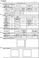
- FIG. 5 is a diagram illustrating an example of the facility register D1 generated at Step S1E.
- FIG. 5 illustrates an example of a case where three road appurtenances different from one another (road appurtenances No. 1 to No. 3) have been recognized at Step S1B from all of the captured images included in the related information.
- the facility register D1 generated at Step S1E has, provided therein, as illustrated in FIG. 5 , for each of the road appurtenances recognized at Step S1B, entry fields for management number D101, manager name D102, route name D103, distance mark D104, facility position information D105 (latitude D106 and longitude D107), upbound or downbound classification D108 indicating whether the road is upbound or downbound, facility classification information D109, inspection date D110, inspection company D111, inspector D112, and degree of damage D113. That is, the facility register D1 has a list of these items D101 to D113 for each of the road appurtenances.
- the second control unit 32 registers, in an entry field for facility position information D105 (latitude D106 and longitude D107), the facility position information generated at Step S1D, based on the captured position information associated with the captured image having the road appurtenance captured therein, the road appurtenance having been recognized at Step S1B.
- facility position information latitude and longitude
- facility position information generated based on captured position information associated with a captured image having the road appurtenance No. 1 captured therein is a latitude, "X1", and a longitude, "Y1", that have thus been registered respectively in the entry fields for latitude D106 and longitude D107.
- the second control unit 32 registers the facility classification information D109 generated at Step S1C in an entry field for facility classification information D109.
- facility classification information indicating a classification of the road appurtenance No. 1 is "sign" that has thus been registered in the entry field for facility classification information D109.
- the second control unit 32 extracts route name information indicating a route name of a road where the road appurtenance is positioned, distance mark information indicating a distance mark where the road appurtenance is positioned on the road, and upbound or downbound classification information indicating whether the road is upbound or downbound, from the map information recorded in the second recording unit 33.
- the route name information, the distance mark information, and the upbound or downbound classification information correspond to correspondence information according to the present invention.
- the second control unit 32 registers the route name information, distance mark information, and upbound or downbound classification information extracted, respectively in entry fields for route name D103, distance mark D104, and upbound or downbound classification D108.
- a manager name of a manager who manages the corresponding road appurtenance is registered in an entry field for manager name D102, in response to a user operation (an input operation for a manager name) on the second input unit 34 by an operator, for example.
- an inspection date, an inspection company, an inspector, and an inspection result for inspection of the corresponding road appurtenance are respectively registered in response to user operations (input operations for the inspection date, inspection company, inspector, and degree of damage) on the second input unit 34 by an operator, for example.
- a management number unique to the corresponding road appurtenance is registered in an entry field for management number D101, but the unique management number may be generated and registered by the second control unit 32 independently or a configuration in which the unique management number is registered in response to a user operation (an input operation for the management number) on the second input unit 34 by an operator may be adopted.
- FIG. 6 is a diagram illustrating an example of the facility specifications D2 generated at Step S1E.
- the facility specifications D2 generated at Step S1E are provided for each of the road appurtenances recognized at Step S1B. That is, because three road appurtenances are included in the facility register D1, three sets of facility specifications D2 corresponding to the facility register D1 illustrated in FIG. 5 are generated.
- FIG. 6 illustrates only the facility specifications D2 corresponding to the road appurtenance No. 1 included in the facility register D1 illustrated in FIG. 5 .
- this set of facility specifications D2 has, provided therein, as illustrated in FIG. 6 , entry fields for classification information D201, positional information D202, structural information D203, installation environment information D204, inspection information D205, map of surrounding area D206, and captured image D207.
- the entry field for classification information D201 includes entry fields for information, such as facility classification information on the corresponding road appurtenance, a manager name of a manager of the road appurtenance, and a management number of the road appurtenance.
- the second control unit 32 registers the facility classification information generated at Step S1C in the entry field for facility classification information included in the classification information D201. Furthermore, a manager name of a manager who manages the corresponding road appurtenance is registered in the entry field for manager name included in the classification information D201, in response to a user operation (an input operation for the manager name) on the second input unit 34 by an operator, for example. A management number unique to the corresponding road appurtenance is registered in the entry field for management number included in the classification information D201, but the second control unit 32 may independently generate and register the management number, or a configuration in which the management number is registered in response to a user operation (an input operation for the management number) on the second input unit 34 by an operator may be adopted.
- the entry field for positional information D202 includes entry fields for information, such as facility position information (latitude and longitude) indicating a position of the corresponding road appurtenance, a road category (national road/major regional road/ ...) of a road where the road appurtenance is positioned, a route name of the road, upbound or downbound classification of the road, and a location of the road appurtenance.
- facility position information latitude and longitude
- a road category national road/major regional road/ 10.1.
- the second control unit 32 registers the facility position information generated at Step S1D in the entry field for facility position information included in the positional information D202. Furthermore, based on the facility position information generated at Step S1D and indicating the position of the road appurtenance, the second control unit 32 extracts road category information indicating a road category of a road where the road appurtenance is positioned, route name information indicating a route name of the road, upbound or downbound classification information indicating whether the road is upbound or downbound, and location information indicating a location (1-1 XX ward XX city XX prefecture, for example) of the road appurtenance, from the map information recorded in the second recording unit 33.
- road category information indicating a road category of a road where the road appurtenance is positioned
- route name information indicating a route name of the road
- upbound or downbound classification information indicating whether the road is upbound or downbound
- location information indicating a location (1-1 XX ward XX city
- the road category information, route name information, upbound or downbound classification information, and location information correspond to correspondence information according to the present invention.
- the second control unit 32 then registers the road category information, route name information, upbound or downbound classification information, and location information extracted, in the entry fields for road category, route name, upbound or downbound classification, and location that are included in the positional information D202.
- the entry field for structural information D203 includes entry fields for information related to a structure of the corresponding road appurtenance, such as a support form, a surface treatment type, and a support base rib form, of the road appurtenance.
- Various types of information are respectively registered in the entry fields for structural information D203 in response to user operations (input operations for the various types of information) on the second input unit 34 by an operator, for example.
- the entry field for installation environment information D204 includes entry fields for information related to an installation environment of the corresponding road appurtenance, such as the installation environment for the road appurtenance (general/bridge/tunnel/ 7), a distance from the coast, whether or not the road appurtenance is in a section where a snow melting agent is spread, whether or not the road appurtenance is in a section under road traffic control caused by wind, and whether or not the road appurtenance is in a section where measures for protection against snow are implemented.
- Various type of information are respectively registered in the entry fields for installation environment information D204 in response to user operations (input operations for the various types of information) on the second input unit 34 by an operator, for example.
- the entry field for inspection information D205 includes entry fields for information, such as a type of inspection for the corresponding road appurtenance (initial inspection/regular inspection/extraordinary inspection/ %), an inspection method (close visual inspection/visual appearance inspection/ %), an inspection date, the last inspection date, an inspection company, and an inspector.
- Various types of information are respectively registered in the entry fields for inspection information D205 in response to user operations (input operations for the various types of information) on the second input unit 34 by an operator, for example.
- the second control unit 32 extracts a map of surrounding area around the road appurtenance from the map information recorded in the second recording unit 33.
- the map of surrounding area corresponds to correspondence information according to the present invention.
- the second control unit 32 registers surrounding area map information in the entry field for map of surrounding area D206, the surrounding area map information having the position of the road appurtenance marked on the map of surrounding area extracted.
- the second control unit 32 registers the captured image or images having the road appurtenance captured therein, the road appurtenance having been recognized at Step S1B, in the entry field for captured images D207.
- inspection result form data D3 (hereinafter, referred to as an inspection result form D3 (see FIG. 10 )) generated based on the facility specifications D2 are used, in addition to the facility specifications D2 described above, in an inspection support system 5 (see FIG. 7 ) described later.
- damage record form data D4 (hereinafter, referred to as a damage record form D4) are generated, of which the details will be described later.
- the road appurtenance is a support
- the road appurtenance is formed of plural members, such as a support body and a support base.
- plural inspected parts such as a support main body, a support joint, and a support branch, have each been assigned to the support body.
- Plural pieces of member unique information that respectively identify the members forming the road appurtenance uniquely and plural pieces of inspected part unique information that respectively identify the plural inspected parts assigned to each of the members uniquely have been registered beforehand in the inspection result form D3.
- inspection result information is registered in the inspection result form D3, the inspection result information being, for example, information on whether or not the plural inspected parts are targets of inspection (yes/no), inspection statuses of the plural inspected parts (done/not done), evaluation classifications of damage to the plural inspected parts (not damaged/damaged/largely damaged), necessity of measures taken for the plural inspected parts (required/not required), and diagnosis classifications for health of the plural inspected parts (healthy/preventive maintenance stage/early action stage/urgent action stage).
- information such as a diagnosis classification for the overall health of the road appurtenance in light of the diagnoses of health of all of the inspected parts of the road appurtenance, is also registered in the inspection result form D3.
- member information Information (hereinafter, referred to as member information) on each of the members forming a road appurtenance identified by a management number is registered in the damage record form D4.
- Member unique information on the members has been registered in the member information beforehand.
- information and inspection images are registered in the member information, the information being, for example, measures taken for the member and an evaluation result for the overall damage to the member in light of evaluation results for damage to the plural inspected parts assigned to the member, the inspection images having the plural inspected parts captured therein, the plural inspected parts having been assigned to the member.
- the management number for one road appurtenance, the member unique information on the member forming the road appurtenance, and the inspected part unique information on the inspected parts assigned to the member are information related to one another.
- inspected part unique information enables derivation of: member unique information on a member including an inspected part based on the inspected part unique information; and a management number of a road appurtenance including the member.
- the inspection support system 5 will be described next.
- FIG. 7 is a diagram illustrating the inspection support system 5.
- the inspection support system 5 is a system that supports inspection of road appurtenances.
- the inspection support system 1 is a system that captures images of inspected parts and inputs inspection results for the inspected parts by use of two devices, an image capturing device 6 and an inspection support device 7 that are independent from each other. That is, in performing inspection of road appurtenances, an operator performing the inspection includes plural operators that are an operator (hereinafter, referred to as a first operator) who operates the inspection support device 7 and an operator (hereinafter, referred to as a second operator) who operates the image capturing device 6. The first operator and the second operator may be the same person.
- the inspection support system 5 is configured to include only one image capturing device 6, but without being limited to this configuration, the inspection support system 5 may be configured to include plural image capturing devices 6.
- the image capturing device 6 is formed of a digital camera, for example. Functions of the image capturing device 6 will be described in a later section, "Operation of Image Capturing Device".
- the inspection support device 7 is formed of, for example, a tablet terminal, a smartphone, a notebook PC (a personal computer), or a wearable device (for example, an eyeglass-type or helmet-type head-mounted display). Functions of the inspection support device 7 will be described in a later section, "Operation of Inspection Support Device".
- FIG. 8 is a flowchart illustrating the operation of the image capturing device 6.
- the image capturing device 6 constantly monitors whether or not any image capturing operation by the second operator has been performed (Step S2A).
- Step S2A Yes
- the image capturing device 6 captures an image of an inspected part to generate an inspection image
- Step S2B the image capturing device 6 repeats Step S2A.
- Step S2B the image capturing device 6 records captured data having the inspection image generated at Step S2B and an image capturing time for the inspection image (for example, a time at which the image capturing operation was performed at Step S2A) in association with each other, in a recording unit (not illustrated in the drawings) in the image capturing device 6 (Step S2C). Thereafter, the image capturing device 6 returns to Step S2A.
- the operation of the inspection support device 7, the operation including first operation and second operation, will be described in order below.
- the first operation of the inspection support device 7 will be described first.
- FIG. 9 is a flowchart illustrating the first operation of the inspection support device 7.
- the inspection support device 7 displays a facility selection screen F1 (see FIG. 11 ) (Step S3A).
- FIG. 10 and FIG. 11 are diagrams for explanation of Step S3A. Specifically, FIG. 10 is a diagram illustrating an example of inspection data D0. FIG. 11 is a diagram illustrating an example of the facility selection screen F1.
- the inspection data D0 ( FIG. 10 ) for a road appurtenances to be inspected have been recorded in a recording unit (not illustrated in the drawings) in the inspection support device 7.
- the inspection support device 7 displays the facility selection screen F1 ( FIG. 11 ) prompting the first operator to select a road appurtenance to be inspected, based on the facility specifications D2 included in the inspection data D0 recorded in the recording unit (not illustrated in the drawings) of the inspection support device 7.
- the facility selection screen F1 is a screen displaying a list of pieces of road appurtenance information F10a, F10b, ... that are pieces of information on plural road appurtenances.
- the pieces of road appurtenance information F10a, F10b, ... are information having, listed therein, for example, as illustrated in FIG. 11 , specification information F11a, F11b, ..., such as "facility classification information " and "management number" of road appurtenances included in the facility specifications D2 corresponding to the corresponding road appurtenances, and captured images F12a, F12b, ... (captured images having the road appurtenances recognized at Step S1B captured therein) of the whole road appurtenances included in the facility specifications D2.
- the facility selecting operation is an operation for selecting the piece of road appurtenance information corresponding to the road appurtenance to be inspected, of the plural pieces of road appurtenance information F10a, F10b, ... that are on the facility selection screen F1.
- Step S3A the inspection support device 7 constantly monitors whether or not a facility selecting operation has been performed by the first operator (Step S3B).
- Step S3B Yes
- the inspection support device 7 displays an inspected part selection screen F2 (see FIG. 12 ) based on the inspection result form D3 corresponding to the road appurtenance selected by the facility selecting operation (Step S3C).
- the inspected part selection screen F2 is constantly displayed from Step S3C, until the flow (Steps S3A to S3L) is ended.
- Step S3B No
- the inspection support device 7 repeats Step S3B.
- FIG. 12 is a diagram illustrating an example of the inspected part selection screen F2.
- the inspected part selection screen F2 is, for example, as illustrated in FIG. 12 , a screen that has names of all of inspected parts listed for a road appurtenance and is provided with combo boxes CB prompting selection of, for each of all of the inspected parts, each of: whether or not the inspected part is a target of inspection (yes/no); an inspection status (done/not done); an evaluation classification of damage (not damaged/damaged/largely damaged); necessity of measures (required/not required); and a diagnosis classification of health (healthy/preventive maintenance stage/early action stage/urgent action stage).
- the inspected part selection screen F2 is provided with, for each of all of the inspected parts, each of an inspection starting button BS for prompting an operation to start inspection of the inspected part and an inspection ending button BE for prompting an operation to end the inspection of the inspected part.
- the inspection starting button BS and the inspection ending button BE may be formed of the same button (hereinafter, referred to as an inspection button).
- the inspection support device 7 has a function of counting the number of times the inspection button is selected. On the basis of a count of the number of times of selection, the inspection support device 7 then determines whether an operation to start inspection or an operation to end inspection has been performed.
- the first operator is able to perform, on the inspection support device 7, an inspection starting operation (an operation of selecting the inspection starting button BS corresponding to the inspected part) to start inspection of the inspected part to be inspected, and an inspection ending operation (an operation of selecting the inspection ending button BE corresponding to the inspected part) to end the inspection of the inspected part.
- an inspection starting operation an operation of selecting the inspection starting button BS corresponding to the inspected part
- an inspection ending operation an operation of selecting the inspection ending button BE corresponding to the inspected part
- a confirmation button BC prompting selection to end inspection of all of the inspected parts of the road appurtenance is provided on the inspected part selection screen F2.
- the first operator is able to perform a confirmation operation (an operation to select the confirmation button BC) on the inspection support device 7 to end the inspection of all of the inspected parts of the road appurtenance.
- Step S3C the inspection support device 7 constantly monitors whether or not an inspection start operation has been performed by the first operator (Step S3D).
- Step S3D the inspection support device 7 determines inspected part unique information on an inspected part corresponding to an inspection starting button BS selected by the inspection starting operation and an inspection starting time (for example, a time at which the inspection starting operation was performed at Step S3D) for the inspected part (Step S3E).
- Step S3D the inspection support device 7 repeats Step S3D.
- Step S3E the inspection support device 7 constantly monitors whether or not an inspection ending operation has been performed by the first operator (Step S3F).
- Step S3F determines inspected part unique information on an inspected part corresponding to an inspection ending button BS selected by the inspection ending operation and an inspection ending time (for example, a time at which the inspection ending operation was performed at Step S3F) for the inspected part (Step S3G).
- Step S3F no inspection ending operation has been performed
- Step S3F repeats Step S3F.
- Step S3D After performing an inspection starting operation (Step S3D) corresponding to an inspected part to be inspected, the first operator instructs the second operator to capture an image of the inspected part. After ending capturing of the image of the inspected part, the second operator lets the first operator know that the capturing of the image has ended. After being informed by the second operator that the capturing of the image has ended, the first operator performs an inspection ending operation (Step S3F) corresponding to the inspected part. That is, at Step S2C, an image capturing time within a time period (a time period from Step S3D to Step S3F) from the inspection starting operation to the inspection ending operation corresponding to the inspected part is associated with the inspection image (the inspection image generated at Step S2B) having the inspected part captured therein.
- the first operator selects each of whether or not the inspected part is a target of inspection, an inspection status, an evaluation classification of damage, necessity of measures, and a diagnosis classification of health, for the inspected part by operating the combo boxes CB.
- the inspection support device 7 registers inspection result information including whether or not the inspected part is a target of inspection, the inspection status, the evaluation classification of damage, the necessity of measures, and the diagnosis classification of health that have been selected, in the inspection result form D3, in association with inspected part unique information identical to the inspected part unique information determined at Steps S3E and S3F (Step S3H).
- a part or all of the operation of the combo boxes CB may be performed after all of the inspection work has ended. Furthermore, after all of the inspection work has ended, the selections made through the combo boxes CB at the time of inspection may be corrected.
- the inspection support device 7 refers to a table TB recorded in the recording unit (not illustrated in the drawings) of the inspection support device 7 and determines whether or not inspected part unique information identical to the inspected part unique information determined at Steps S3E and S3G has been registered in the table TB (Step S3I).
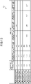
- FIG. 13 is a diagram illustrating an example of the table TB.
- the table TB ( FIG. 13 ) has been recorded in the recording unit (not illustrated in the drawings) that is in the inspection support device 7.
- the table TB is provided for each of all of road appurtenances included in the facility register D1 described above.
- FIG. 13 illustrates only one of the tables TB, the one corresponding to one of the road appurtenances.
- plural pieces of inspection-related information are registered in the table TB, the inspection-related information having inspected part unique information and time stamps in association with each other, the inspected part unique information being on that inspected part, the time stamps indicating inspection starting times and inspection ending times for the inspected part.
- FIG. 13 illustrates only one of the tables TB, the one corresponding to one of the road appurtenances.
- the inspection-related information DA1 is information having inspected part unique information ID1, time stamps indicating an inspection starting time ST1 and an inspection ending time EN1, and time stamps indicating an inspection starting time ST1' and an inspection ending time EN1', in association with one another.
- the inspected part unique information ID1 is the inspected part unique information determined at Steps S3E and S3G executed for the first time with respect to the first inspected part. Furthermore, the time stamps indicating the inspection starting time ST1 and the inspection ending time EN1 are the time stamps determined at Steps S3E and S3G executed for the first time with respect to the first inspected part. In addition, the time stamps indicating the inspection starting time ST1' and the inspection ending time EN1' are the time stamps determined at Steps S3E and S3G executed for the second time with respect to the first inspected part.
- the inspection-related information DA2 is information having inspected part unique information ID2 and time stamps, in association with each another, the time stamps indicating an inspection starting time ST2 and an inspection ending time EN2.
- the inspected part unique information ID2 is the inspected part unique information determined at Steps S3E and S3G executed for the first time with respect to the second inspected part. Furthermore, the time stamps indicating the inspection starting time ST2 and the inspection ending time EN2 are the time stamps determined at Steps S3E and S3G executed for the first time with respect to the second inspected part.
- the other pieces of inspection-related information DA3, DA4, and DA6 also have configurations similar to that of the inspection-related information DA2.
- the inspection-related information DA5 is information having inspected part unique information ID5, time stamps indicating an inspection starting time ST5 and an inspection ending time EN5, time stamps indicating an inspection starting time ST5' and an inspection ending time EN5', and time stamps indication an inspection starting time ST5" and an inspection ending time EN5", in association with one another.
- the inspected part unique information ID5 is the inspected part unique information determined at Steps S3E and S3G executed for the first time with respect to the fifth inspected part.
- the time stamps indicating the inspection starting time ST5 and the inspection ending time EN5 are the time stamps determined at Steps S3E and S3G executed for the first time with respect to the fifth inspected part.
- the time stamps indicating the inspection starting time ST5' and the inspection ending time EN5' are the time stamps determined at Steps S3E and S3G executed for the second time with respect to the fifth inspected part.
- the time stamps indicating the inspection starting time ST5" and the inspection ending time EN5" are the time stamps determined at Steps S3E and S3G executed for the third time with respect to the fifth inspected part.
- Steps S3J and S3K will be described below.
- the first case is a case where the inspected part unique information ID1, the inspection starting time ST1, and the inspection ending time EN1 have been determined at Steps S3E and S3G executed for the first time with respect to the first inspected part. Furthermore, in the first case, the inspection-related information DA1 has not been registered in the table TB before Steps S3E and S3G for the first time.
- the inspection support device 7 determines that the inspected part unique information ID1 identical to the inspected part unique information ID1 determined at Steps S3E and S3G for the first time has not been registered in the table TB (Step S3I: No). The inspection support device 7 then registers new inspection-related information DA1 in the table TB by associating the inspected part unique information ID1 determined at Steps S3E and S3G for the first time with the time stamps indicating the inspection starting time ST1 and the inspection ending time EN1 (Step S3J).
- the second case is a case where the inspected part unique information ID1, the inspection starting time ST1', and the inspection ending time EN1' have been determined at Steps S3E and S3G executed for the second time with respect to the first inspected part. That is, in the second case, before Steps S3E and S3G, the inspection-related information DA1 has been registered in the table TB, but the time stamps for the inspection starting time ST1' and inspection ending time EN1' are not included in the inspection-related information DA1.
- the inspection support device 7 determines that the inspected part unique information ID1 identical to the inspected part unique information ID1 determined at Steps S3E and S3G for the second time has been registered in the table TB (Step S3I: Yes).
- the inspection support device 7 then updates the inspection-related information DA1 by associating the time stamps indicating the inspection starting time ST1' and inspection ending time EN1' determined at Steps S3E and S3G for the second time with the inspected part unique information ID1 identical to the inspected part unique information ID1 determined at Steps S3E and S3G for the second time (Step S3K).
- Step S3J or Step S3K the inspection support device 7 determines whether or not a confirmation operation has been performed by the first operator (Step S3L).
- Step S3L In a case where a confirmation operation has not been performed (Step S3L: No), the inspection support device 7 returns to Step S3D. On the contrary, if a confirmation operation has been performed (Step S3L: Yes), the inspection support device 7 ends the flow (first operation).
- FIG. 14 is a flowchart illustrating the second operation of the inspection support device 7.
- the inspection support device 7 establishes connection for communication with the image capturing device 6 and receives the captured data recorded in the recording unit (not illustrated in the drawings) that is in the image capturing device 6 (Step S3M).
- a configuration in which the second operation is executed after and following the first operation may be adopted, or a configuration in which the second operation is executed independently from the first operation after the first operation may be adopted.
- a confirmation operation triggers execution of Step S3M.
- a predetermined operation by a user on the inspection support device 7 triggers execution of Step S3M.
- the inspection support device 7 updates the inspection-related information by associating the inspection images in the captured data received at Step S3M with the inspected part unique information registered in the table TB recorded in the recording unit (not illustrated in the drawings) that is in the inspection support device 7 (Step S3N).
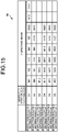
- FIG. 15 is a diagram for explanation of Step S3N. Specifically, FIG. 15 is a diagram illustrating an example of the table TB. FIG. 15 is a diagram corresponding to FIG. 13 . Furthermore, for convenience of explanation, illustration of the time stamps in the inspection-related information DA1 to DA6 has been omitted in FIG. 15 .
- inspection images IM1 to IM35 have been captured in the order of the inspection images IM1 to IM35. More specifically, the inspection images IM1 to IM5 are inspection images each captured in the time period from the inspection starting time ST1 to the inspection ending time EN1.
- the inspection images IM6 to IM11 are inspection images each captured in the time period from the inspection starting time ST2 to the inspection ending time EN2.
- the inspection images IM12 to IM14 are inspection images each captured in the time period from the inspection starting time ST3 to the inspection ending time EN3.
- the inspection images IM15 to IM20 are inspection images each captured in the time period from the inspection starting time ST4 to the inspection ending time EN4.
- the inspection images IM21 and IM22 are inspection images each captured in the time period from the inspection starting time ST5 to the inspection ending time EN5.
- the inspection images IM23 to IM28 are inspection images each captured in the time period from the inspection starting time ST6 to the inspection ending time EN6.
- the inspection images IM29 to IM31 are inspection images each captured in the time period from the inspection starting time ST1' to the inspection ending time EN1'.
- the inspection images IM32 to IM33 are inspection images each captured in the time period from the inspection starting time ST5' to the inspection ending time EN5'.
- the inspection images IM34 and IM35 are inspection images each captured in the time period from the inspection starting time ST5" to the inspection ending time EN5".
- Step S3N will be described below based on the example in FIG. 15 .
- the inspection support device 7 checks the time stamps included in the inspection-related information DA1 to DA6 registered in the table TB against the image capturing times included in the captured data received at Step S3M. The inspection support device 7 then updates the inspection-related information by associating the inspection images associated with the image capturing times in the time period from the inspection starting time to the inspection ending time with the inspected part unique information associated with the time stamps indicating the inspection starting time and the inspection ending time.
- the inspection support device 7 updates the inspection-related information DA1 by associating the inspection images IM1 to IM5 and IM29 to IM31 with the inspected part unique information ID1.
- the inspection support device 7 updates the inspection-related information DA2 by associating the inspection images IM6 to IM11 with the inspected part unique information ID2.
- the inspection support device 7 also updates the inspection-related information DA3 by associating the inspection images IM12 to IM14 with the inspected part unique information ID3.
- the inspection support device 7 also updates the inspection-related information DA4 by associating the inspection images IM15 to IM20 with the inspected part unique information ID4.
- the inspection support device 7 also updates the inspection-related information DA5 by associating the inspection images IM21, IM22, and IM32 to IM35 with the inspected part unique information ID5.
- the inspection support device 7 also updates the inspection-related information DA6 by associating the inspection images IM23 to IM28 with the inspected part unique information ID6.
- the inspection support device 7 registers member information for each member in the damage record form D4 based on the inspection result form D3 having the inspection result information registered therein at Step S3H and the inspection-related information updated at Step S3N (Step S3O). Thereafter, the inspection support device 7 ends the flow (second operation).
- the inspection support device 7 registers the member information in the damage record form D3 by associating inspection result information and inspection images, with the member unique information, the inspection result information having been registered in the inspection result form D3 and associated with inspected part unique information related to the member unique information on the member, the inspection images having been registered in the table TB and associated with the inspected part unique information related to the member unique information.
- the first operator may perform, on the inspection support device 7, a display operation for a damage record form screen.
- the display operation for a damage record form screen is an operation to select an area Ar1 corresponding to a member desired to be checked, of plural areas Ar1 ( FIG. 12 ) having names of members listed therein on the inspected part selection screen F2.
- the inspection support device 7 displays a damage record form screen F3 (see FIG. 16 ) based on the damage record form D3 corresponding to a member selected by the display operation.
- FIG. 16 is a diagram illustrating an example of the damage record form screen F3.
- the damage record form screen F3 has, as illustrated in FIG. 16 , for example, listed thereon, information, such as the member name, the evaluation result for the overall damage to the member, and measures taken for the member, and the inspection images having the plural inspected parts captured therein, the plural inspected parts having been assigned to the member.
- the first embodiment described above has the following effects.
- the second control unit 32 in the support information generating device 3 analyzes plural captured images included in related information generated beforehand by the related information generating device 2, and recognizes any road appurtenance captured in at least one captured image of the plural captured images. Furthermore, the second control unit 32 determines a classification of the road appurtenance captured in the captured image and generates facility classification information indicating the classification. The second control unit 32 then generates support information (the facility register D1 and facility specifications D2) having the facility classification information and facility position information associated with each other, the facility position information indicating a position of the road appurtenance, the facility position information corresponding to captured position information associated with the captured image having the road appurtenance captured therein.
- the support information generating device 3 is able to generate the support information substantially automatically, and thus without imposing the conventional cumbersome operation on operators in generating the support information, the support information generating device 3 enables the convenience to be improved.
- the second control unit 32 in the support information generating device 3 extracts correspondence information corresponding to the position of the road appurtenance from map information that has been recorded in the second recording unit 33.
- the second control unit 32 then generates support information having the correspondence information associated with the facility position information.
- the facility classification information, facility position information, and correspondence information, for example are registered in the support information, and thus management of the road appurtenance is facilitated based on the support information and the convenience is able to be improved even more.
- the second control unit 32 in the support information generating device 3 generates the facility position information based on the captured position information.
- positional information higher in accuracy of the position of the road appurtenance is able to be registered in the support information.
- This second embodiment is different from the first embodiment described above only in that its second control unit 32 having the support information generating function for generating support information (the facility register D1 and facility specifications D2) by the flow in FIG. 4 additionally has a support information updating function for updating the support information generated.
- This support information updating function will be described in the following section, "Information Updating Method".
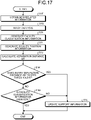
- FIG. 17 is a flowchart illustrating an information updating method according to the second embodiment.
- support information (the facility register D1 and facility specifications D2) has been generated already by the flow in FIG. 4 and the support information has been recorded in the second recording unit 33 already. Furthermore, it is also assumed that related information different from the related information obtained at Step S1A at the related information generating device 2 has been newly generated and the recording medium 4 having this new related information recorded therein has been inserted in the second reader-writer 31.
- This new related information is plural captured images sequentially captured by the first image capturing unit 25 and information generated based on captured position information sequentially measured by the first position measuring unit 26, when a road where a vehicle was travelling when the related information obtained at Step S1A was generated is being travelled again.
- the related information obtained at Step S1A, and the captured images and captured position information that are included in the related information respectively correspond to first related information, first captured images, and first captured position information, according to the present invention.
- the facility classification information and facility position information included in the support information (the facility register D1 and facility specifications D2) generated already by the flow in FIG. 4 respectively correspond to first facility classification information and first facility position information, according to the present invention.
- the facility classification information and facility position information included in the support information generated already by the flow of FIG. 4 will hereinafter be referred to as the first facility classification information and the first facility position information.
- the new related information and the captured images and captured position information that are included in the new related information respectively correspond to second related information, second captured images, and second captured position information, according to the present invention.
- the second control unit 32 outputs a control signal to the second reader-writer 31, in response to a user operation by an operator on the second input unit 34 to start update of the support information.
- the second reader-writer 31 retrieves the new related information recorded in the recording medium 4 (Step S1F).
- the new related information retrieved by the second reader-writer 31 is then recorded in the second recording unit 33.
- Step S1F the second control unit 32 reads the new related information recorded in the second recording unit 33 and analyzes the plural captured images included in the new related information (Step S1G).
- the method of analyzing the captured images is the same as that described above with respect to Step S1B according to the first embodiment.
- the second control unit 32 thereby recognizes any road appurtenance captured in at least one captured image of the plural captured images included in the new related information.
- the second control unit 32 determines the classification (among sign, lamp, and information board, for example) of any road appurtenance recognized at Step S1G and generates facility classification information indicating that classification (Step S1H).
- This facility classification information corresponds to second facility classification information according to the present invention.
- the facility classification information will hereinafter be referred to as the second facility classification information.
- the second control unit 32 After Step S1H, the second control unit 32 generates facility position information indicating a position of the road appurtenance, based on captured position information associated with the captured image having the road appurtenance captured therein (Step S1I), the road appurtenance having been recognized at Step S1G.
- the method of generating the facility position information is the same as that described above with respect to Step S1D according to the first embodiment.
- This facility position information corresponds to second facility position information according to the present invention.
- the facility position information will hereinafter be referred to as the second facility position information.
- the second control unit 32 reads the first facility position information on each of all of the road appurtenances included in the facility register D1 recorded in the second recording unit 33.
- the second control unit 32 calculates a separation distance ⁇ R between the position of each of the road appurtenances based on its first facility position information and the position of the road appurtenance (the road appurtenance recognized at Step S1G) based on the second facility position information generated at Step S1I (Step S1J).
- Step S1J the second control unit 32 determines whether or not all of the separation distances ⁇ R calculated at Step S1J exceed a predetermined threshold Rj (Step S1K).
- Step S1K the second control unit 32 recognizes the road appurtenance recognized at Step S1G as a road appurtenance that has been newly provided on the road.
- the second control unit 32 then updates the support information recorded in the second recording unit 33 (Step S1L). Thereafter, the second control unit 32 ends the flow.
- the second control unit 32 newly registers both the second facility classification information generated at Step S1H and the second facility position information generated at Step S1I, for the road appurtenance newly provided (newly registers as a road appurtenance No. 4, in the example of FIG. 5 ), for example, in the facility register D1. Furthermore, the second control unit 32 generates the facility specifications D2 corresponding to the road appurtenance newly provided.
- the second control unit 32 determines whether or not the first facility classification information associated with the position (first facility position information) of the road appurtenance (hereinafter, referred to as a first road appurtenance) having the separation distance ⁇ R equal to or less than the threshold Rj from the road appurtenance (hereinafter, referred to as a second road appurtenance) recognized at Step S1G is the same as the second facility classification information generated at Step S1H for the second road appurtenance (Step S1M).
- a first road appurtenance having the separation distance ⁇ R equal to or less than the threshold Rj from the road appurtenance (hereinafter, referred to as a second road appurtenance) recognized at Step S1G is the same as the second facility classification information generated at Step S1H for the second road appurtenance (Step S1M).
- the second control unit 32 determines that the second road appurtenance is a road appurtenance (for example, a road appurtenance already provided on the road within the jurisdiction managed by the manager of the municipality, for example) already registered in the facility register D1, and ends the flow.
- a road appurtenance for example, a road appurtenance already provided on the road within the jurisdiction managed by the manager of the municipality, for example
- Step S1M the second control unit 32 recognizes the second road appurtenance as a road appurtenance that has been newly provided in place of the first road appurtenance.
- the second control unit 32 then proceeds to Step S1L and updates the support information recorded in the second recording unit 33.
- the second control unit 32 deletes information related to the first road appurtenance registered in the facility register D1. Furthermore, the second control unit 32 deletes the facility specifications D2 corresponding to the first road appurtenance.
- the second control unit 32 also newly registers the second facility classification information generated at Step S1H and the second facility position information generated at Step S1I, for the second road appurtenance, for example, in the facility register D1. Furthermore, the second control unit 32 generates the facility specifications D2 corresponding to the second road appurtenance.
- the second embodiment described above has the following effects, in addition to effects similar to those of the first embodiment described above.
- the second control unit 32 in the support information generating device 3 updates support information by the information updating method described above.
- the support information generating device 3 is capable of readily generating support information for a case where a road appurtenance has been removed or a case where a road appurtenance has been newly installed, and thus enables the convenience to be improved even more.
- the above described support information generating device 3 generates support information based on related information generated beforehand by the related information generating device 2.
- a support information generating device is formed of a drive recorder, for example, that is installed in a vehicle, and generates support information in real time when the vehicle is capturing images of road appurtenances, for example, while travelling on a road or roads within the jurisdiction managed by a manager of a municipality, for example.
- FIG. 18 is a block diagram illustrating a support information generating device 8 according to the third embodiment.
- the support information generating device 8 includes, as illustrated in FIG. 18 , a third control unit 81, a third recording unit 82, a third input unit 83, a third display unit 84, a third image capturing unit 85, a third position measuring unit 86, and a communication unit 87, and these units 81 to 87 are configured to be connected to one another via a bus 88.
- the third control unit 81 corresponds to a processor according to the present invention.
- This third control unit 81 is formed of a CPU or an FPGA, for example, and controls the overall operation of the support information generating device 8 according to a program (including a support information generating program according to the present invention) recorded in the third recording unit 82.
- the third control unit 81 has functions of an image analyzing unit, a classification determining unit, a position correcting unit, and an information generating unit, according to the present invention. Functions of the third control unit 81 will be described in a later section, "Support Information Generating Method".
- the third recording unit 82 has, recorded therein, the program (including the support information generating program according to the present invention) executed by the third control unit 81, information required for processing by the third control unit 81, and information that has been processed by the third control unit 81 (including captured images generated by the third image capturing unit 85), for example.
- Examples of the information required for the processing by the third control unit 81 include the map information and trained model recorded in the second recording unit 33 described above with respect to the first embodiment.
- the third input unit 83 is formed of buttons, switches, or a touch panel for receiving user operations, for example, and outputs operation signals corresponding to the user operations, to the third control unit 81.
- the third display unit 84 is formed of a display using liquid crystal or organic EL, for example, and displays various images under control of the second control unit 81.
- a part or all of functions of the third input unit 83 may be provided as a touch panel on a surface of the third display unit 84.
- the third image capturing unit 85 corresponds to an image capturing unit according to the present invention. Specific illustration of the third image capturing unit 85 in the drawings has been omitted but the third image capturing unit 85 includes a lens unit, an imaging element, and a signal processing unit.
- the lens unit captures a subject image and forms the subject image on an imaging plane of the imaging element.
- the imaging element is formed of a CCD or a CMOS, for example, that receives the subject image formed by the lens unit and converts the subject image into an electric signal.
- the signal processing unit performs signal processing (for example, A/D conversion) on the electric signal from the imaging element and outputs image data (hereinafter, referred to as a captured image).
- the third position measuring unit 86 corresponds to a position measuring unit according to the present invention.
- the third position measuring unit 86 receives trajectory information transmitted from plural GPS satellites forming a global positioning system (GPS) that is a position measuring means that measures positions of objects on the earth, the trajectory information being on the satellites, and the third position measuring unit 86 outputs, based on the trajectory information received, captured position information indicating a position (latitude and longitude) of the support information generating device 3 (third image capturing unit 85).
- GPS global positioning system
- the communication unit 87 performs communication (wireless communication or wired communication) of various data (support information generated, for example) with an external device (not illustrated in the drawings) of the inspection support device 7 described above with respect to the first embodiment, for example, under control of the third control unit 81, according to a predetermined protocol.
- a configuration in which support information generated is transmitted to an external device by communication is adopted for this third embodiment, but without being limited to this configuration, a configuration in which the support information is transferred to the external device using a portable recording medium like the recording medium 4 described above with respect to the first embodiment may be adopted.
- FIG. 19 is a flowchart illustrating the support information generating method.
- the support information generating device 8 is installed in a vehicle and the vehicle is travelling on a road within the jurisdiction managed by a manager of a municipality, for example.
- the third control unit 81 outputs a control signal to each of the third image capturing unit 85 and the third position measuring unit 86, in response to a user operation by an operator on the third input unit 83 to start generation of support information.
- captured images captured are sequentially output from the third image capturing unit 85 and captured position information generated by position measurement is sequentially output from the third position measuring unit 86 in synchronization with the timing of the output of the captured images (Step S4A).
- Step S4A the third control unit 81 sequentially analyzes the captured images sequentially output from the third image capturing unit 85 (Step S4B).
- the method of analyzing the captured images is the same as that described above with respect to Step S1B according to the first embodiment.
- the third control unit 81 thereby recognizes any road appurtenance captured in the captured images.
- the third control unit 81 determines the classification (among sign, lamp, and information board, for example) of any road appurtenance recognized at Step S4B and generates facility classification information indicating the classification (Step S4C).
- Step S4C the third control unit 81 generates, based on the captured position information output from the third position measuring unit 86 substantially at the same time as the captured image having the road appurtenance captured therein, the road appurtenance having been recognized at Step S4B, facility position information indicating a position of the road appurtenance (Step S4D).
- the method of generating the facility position information is the same as that described above with respect to Step S1D according to the first embodiment.
- the number of pieces of captured position information generated per unit time by the third position measuring unit 86 is less than the number of captured images generated per unit time (frame rate) by the third image capturing unit 85.
- the third control unit 81 generates that captured position information by interpolation (for example, linear interpolation).
- Step S4D the third control unit 81 generates support information (the facility register D1 and facility specifications D2) having the facility classification information generated at Step S4C and the facility position information generated at Step S4D associated with each other, similarly to Step S1E described above with respect to the first embodiment (Step S4E). Thereafter, the third control unit 81 ends the flow.
- support information the facility register D1 and facility specifications D2
- the support information generating device 8 configured to generate support information in real time while capturing images of road appurtenances, for example, like in the third embodiment described above achieves effects similar to those of the first embodiment described above.
- examples of facilities according to the present invention are road appurtenances, but without being limited to road appurtenances, the facilities may include bridges and tunnels.
- a support information generating device As described above, a support information generating device, a support information generating system, a support information generating method, and a support information generating program according to the present invention are useful for generating support information for supporting inspection of road appurtenances, such as signs and lamps.
Landscapes
- Engineering & Computer Science (AREA)
- Theoretical Computer Science (AREA)
- Physics & Mathematics (AREA)
- General Physics & Mathematics (AREA)
- Databases & Information Systems (AREA)
- Business, Economics & Management (AREA)
- Human Resources & Organizations (AREA)
- General Engineering & Computer Science (AREA)
- Data Mining & Analysis (AREA)
- Multimedia (AREA)
- Software Systems (AREA)
- Strategic Management (AREA)
- Computer Vision & Pattern Recognition (AREA)
- Entrepreneurship & Innovation (AREA)
- Economics (AREA)
- Operations Research (AREA)
- Health & Medical Sciences (AREA)
- Evolutionary Computation (AREA)
- Artificial Intelligence (AREA)
- General Business, Economics & Management (AREA)
- General Health & Medical Sciences (AREA)
- Marketing (AREA)
- Medical Informatics (AREA)
- Quality & Reliability (AREA)
- Computing Systems (AREA)
- Tourism & Hospitality (AREA)
- Development Economics (AREA)
- Educational Administration (AREA)
- Game Theory and Decision Science (AREA)
- Remote Sensing (AREA)
- Computational Linguistics (AREA)
- Traffic Control Systems (AREA)
- Image Analysis (AREA)
- Management, Administration, Business Operations System, And Electronic Commerce (AREA)
- Processing Or Creating Images (AREA)
Abstract
Description
- The present invention relates to a support information generating device, a support information generating system, a support information generating method, and a support information generating program.
- A system conventionally known as an inspection support system for supporting inspection of objects including road appurtenances, such as signs and lamps, captures images of inspected parts and inputs inspection results for the inspected parts using two devices (an image capturing device and an inspection terminal) that are independent from each other (see, for example, Patent Literature 1).
- Facilities, such as road appurtenances, inspected using the inspection support system described in
Patent Literature 1 are normally managed using a facility register (support information). This facility register has a list of information for each facility that is managed by a manager of a municipality, for example, and that is within the jurisdiction of the municipality, the information including facility position information (latitude and longitude, for example) indicating the position of the facility, facility classification information indicating the classification (among sign, lamp, or information board, for example) of the facility, and damage information indicating the degree of damage to the facility. That is, the manager is able to know information including the facility to be inspected and the degree of damage to the facility, by referring to the facility register. - The facility register is conventionally generated as follows.
- An operator searches for facilities, such as road appurtenances, within the jurisdiction, by walking within the jurisdiction. Furthermore, when the operator finds any facility, such as a road appurtenance, the operator checks the position of the facility and takes a note of facility position information (latitude and longitude, for example) indicating the position checked and facility classification information (among sign, lamp, and information board, for example) indicating the classification of the facility.
- The operator then generates a facility register having a list of facility position information and facility classification information for each of all of the facilities found within the jurisdiction. After inspection of the facilities listed in the facility register is performed, the operator additionally registers damage information indicating the degrees of damage to the facilities in the facility register, the damage information being results of the inspection.
- Patent Literature 1:
Japanese Unexamined Patent Application Publication No. 2017-228249 - However, this conventional method of generating a facility register imposes cumbersome operation on the operator and thus has a problem of not being able to improve the convenience.
- The present invention has been made in view of the above, and an object of the present invention is to provide a support information generating device, a support information generating system, a support information generating method, and a support information generating program that enable the convenience to be improved. Solution to Problem
- In order to solve the above-described problem and achieve the object, a support information generating device according to the present invention includes: a related information obtaining unit configured to obtain first related information including a plurality of first captured images sequentially captured in chronological order, the plurality of first captured images being associated respectively with first captured position information indicating captured positions at which the first captured images are captured; an image analyzing unit configured to analyze the plurality of first captured images and recognize a specific facility captured in at least one first captured image of the plurality of first captured images; a classification determining unit configured to determine a classification of the specific facility captured in the first captured image and generate first facility classification information indicating the classification; and an information generating unit configured to generate support information including the first facility classification information and first facility position information associated with each other, the first facility position information indicating a position of the specific facility based on the first captured position information associated with the first captured image in which the specific facility is captured.
- In the above-described support information generating device according to the present invention, in a case where a plurality of the specific facilities different from one another have been recognized by the image analyzing unit, the information generating unit is configured to generate the support information including a list of the first facility classification information and the first facility position information for each of the recognized specific facilities.
- In the above-described support information generating device according to the present invention, in a case where a plurality of the specific facilities different from one another have been recognized by the image analyzing unit, the information generating unit is configured to generate the support information for each of the recognized specific facilities.
- The above-described support information generating device according to the present invention further includes: a map information recording unit configured to record map information, wherein the information generating unit is configured to extract, from the map information, correspondence information corresponding to the position of the specific facility based on the first facility position information corresponding to the first captured position information associated with the first captured image in which the specific facility is captured, and generate the support information including the first facility position information associated with the correspondence information.
- The above-described support information generating device according to the present invention further includes: a position correcting unit configured to generate the first facility position information from the first captured position information, wherein the position correcting unit is configured to estimate, based on a size of the specific facility recognized by the image analyzing unit in the first captured image, a distance from the captured position to the specific facility, and correct, based on the estimated distance, the captured position to generate the first facility position information.
- In the above-described support information generating device according to the present invention, the related information obtaining unit is configured to obtain second related information including a plurality of second captured images sequentially captured in chronological order, the plurality of second captured images being associated respectively with second captured position information indicating captured positions at which the second captured images are captured, the image analyzing unit is configured to analyze the plurality of second captured images, and recognize the specific facility captured in at least one second captured image of the plurality of second captured images, the classification determining unit is configured to determine a classification of the specific facility captured in the second captured image, and generate second facility classification information indicating the classification, and the information generating unit is configured to make a comparison between: the second facility classification information and second facility position information indicating a position of the specific facility and corresponding to the second captured position information associated with the second captured image in which the specific facility is captured; and the first facility classification information and the first facility position information that are included in the support information, and update the support information based on a result of the comparison.
- A support information generating device according to the present invention includes: an image capturing unit configured to sequentially output captured images that have been captured; a position measuring unit configured to measure a captured position, and generate captured position information indicating the captured position; an image analyzing unit configured to sequentially analyze the captured images output from the image capturing unit, and recognize a specific facility captured in the captured images; a classification determining unit configured to determine a classification of the specific facility captured in the captured images, and generate facility classification information indicating the classification; and an information generating unit configured to generate support information including the facility classification information and facility position information associated with each other, the facility position information indicating a position of the specific facility based on the captured position information indicating a captured position of the captured image in which the specific facility is captured.
- A support information generating system according to the present invention includes: the above-described support information generating device; and a related information generating device configured to generate the first related information, and the related information generating device including an image capturing unit configured to generate the plurality of first captured images, and a position measuring unit configured to measure a position of the image capturing unit, and generate the first captured position information indicating the position.
- A support information generating method according to the present invention executed by a processor of a support information generating device includes: obtaining related information including a plurality of captured images captured sequentially in chronological order, the plurality of captured images being associated respectively with captured position information indicating captured positions at which the captured images are captured; analyzing the plurality of captured images and recognizing a specific facility captured in at least one first captured image of the plurality of first captured images; determining a classification of the specific facility captured in the captured image and generating facility classification information indicating the classification; and generating support information including the facility classification information and facility position information associated with each other, the facility position information indicating a position of the specific facility based on the captured position information associated with the captured image in which the specific facility is captured.
- A support information generating method according to the present invention executed by a processor of a support information generating device includes: causing an image capturing unit to sequentially output captured images that have been captured; causing a position measuring unit to measure a position of the image capturing unit and to generate captured position information indicating the position; sequentially analyzing the captured images output from the image capturing unit and recognizing a specific facility captured in the captured images; determining a classification of the specific facility captured in the captured images and generating facility classification information indicating the classification; and generating support information including the facility classification information and facility position information associated with each other, the facility position information indicating a position of the specific facility based on the captured position information indicating a captured position of the captured image in which the specific facility is captured.
- A support information generating program according to the present invention to be executed by a processor of a support information generating device instructs the processor to execute: obtaining related information including a plurality of captured images captured sequentially in chronological order, the plurality of captured images being associated respectively with captured position information indicating captured positions at which the captured images are captured; analyzing the plurality of captured images and recognizing a specific facility captured in at least one first captured image of the plurality of first captured images; determining a classification of the specific facility captured in the captured image and generating facility classification information indicating the classification; and generating support information including the facility classification information and facility position information associated with each other, the facility position information indicating a position of the specific facility based on the captured position information associated with the captured image in which the specific facility is captured.
- A support information generating program according to the present invention to be executed by a processor of a support information generating device instructs the processor to execute: causing an image capturing unit to sequentially output captured images that have been captured; causing a position measuring unit to measure a position of the image capturing unit and to generate captured position information indicating the position; sequentially analyzing the captured images output from the image capturing unit and recognizing a specific facility captured in the captured images; determining a classification of the specific facility captured in the captured images and generating facility classification information indicating the classification; and generating support information including the facility classification information and facility position information associated with each other, the facility position information indicating a position of the specific facility based on the captured position information indicating a captured position of the captured image in which the specific facility is captured.
- A support information generating device, a support information generating system, a support information generating method, and a support information generating program according to the present invention enable the convenience to be improved.
-
-
FIG. 1 is a diagram illustrating a support information generating system according to a first embodiment. -
FIG. 2 is a block diagram illustrating a related information generating device. -
FIG. 3 is a block diagram illustrating a support information generating device. -
FIG. 4 is a flowchart illustrating a support information generating method. -
FIG. 5 is a diagram illustrating an example of a facility register generated at Step S1E. -
FIG. 6 is a diagram illustrating an example of facility specifications generated at Step S1E. -
FIG. 7 is a diagram illustrating an inspection support system. -
FIG. 8 is a flowchart illustrating operation of an image capturing device. -
FIG. 9 is a flowchart illustrating first operation of an inspection support device. -
FIG. 10 is a diagram for explanation of Step S3A. -
FIG. 11 is a diagram for explanation of Step S3A. -
FIG. 12 is a diagram illustrating an example of an inspected part selection screen. -
FIG. 13 is a diagram illustrating an example of a table. -
FIG. 14 is a flowchart illustrating second operation of the inspection support device. -
FIG. 15 is a diagram for explanation of Step S3N. -
FIG. 16 is a diagram illustrating an example of a damage record form screen. -
FIG. 17 is a flowchart illustrating an information updating method according to a second embodiment. -
FIG. 18 is a block diagram illustrating a support information generating device according to a third embodiment. -
FIG. 19 is a flowchart illustrating a support information generating method. - Modes for implementing the present invention (hereinafter, embodiments) will be described below by reference to the drawings. The present invention is not limited by the embodiments described below. The same reference sign is assigned to the same portions throughout the drawings.
-
FIG. 1 is a diagram illustrating a supportinformation generating system 1 according to a first embodiment. - The support
information generating system 1 is a system that generates support information for supporting inspection of road appurtenances (corresponding to facilities according to the present invention), such as signs and lamps. Examples of the support information, which will be specifically described later, include facility register data (hereinafter, referred to as a facility register) and facility specification data (hereinafter, referred to as facility specifications). - This support
information generating system 1 includes, as illustrated inFIG. 1 , a relatedinformation generating device 2, a supportinformation generating device 3, and arecording medium 4 that is portable. - The
recording medium 4 is a portable recording medium for transferring data between the relatedinformation generating device 2 and the supportinformation generating device 3 and is configured to be attachable to and detachable from each of the relatedinformation generating device 2 and the supportinformation generating device 3. Configuration of Related Information Generating Device -
FIG. 2 is a block diagram illustrating the relatedinformation generating device 2. - The related
information generating device 2 is formed of a driver recorder to be installed in a vehicle, for example. This relatedinformation generating device 2 is configured to include, as illustrated inFIG. 2 , a first control unit 21, afirst recording unit 22, a first input unit 23, afirst display unit 24, a firstimage capturing unit 25, a firstposition measuring unit 26, and a first reader-writer 27, and to have these units 21 to 27 connected to one another via a bus 28. - The first control unit 21 is formed of a central processing unit (CPU) or a field-programmable gate array (FPGA), for example, and controls the overall operation of the related
information generating device 2 according to a program recorded in thefirst recording unit 22. - The
first recording unit 22 has, recorded therein, the program executed by the first control unit 21, information required for processing by the first control unit 21, and information that has been processed by the first control unit 21, for example. - The first input unit 23 is formed of buttons, switches, or a touch panel for receiving user operations, for example, and outputs operation signals corresponding to the user operations, to the first control unit 21.
- The
first display unit 24 is formed of a display using liquid crystal or organic electroluminescence (EL), for example, and displays various images, under control of the first control unit 21. A part or all of functions of the first input unit 23 may be provided as a touch panel on a surface of thefirst display unit 24. - The first
image capturing unit 25 corresponds to an image capturing unit according to the present invention. Specific illustration of the firstimage capturing unit 25 in the drawings has been omitted but the firstimage capturing unit 25 includes a lens unit, an imaging element, and a signal processing unit. The lens unit captures a subject image and forms the subject image on an imaging plane of the imaging element. The imaging element is formed of a charge coupled device (CCD) or a complementary metal oxide semiconductor (CMOS), for example, which receives the subject image formed by the lens unit and converts the subject image into an electric signal. The signal processing unit performs signal processing (for example, A/D conversion) on the electric signal from the imaging element and outputs image data (hereinafter, referred to as a captured image). - The first
position measuring unit 26 corresponds to a position measuring unit according to the present invention. This firstposition measuring unit 26 receives trajectory information transmitted from plural GPS satellites forming a global positioning system (GPS) that is a position measuring means that measures positions of objects on the earth, the trajectory information being on the satellites, and outputs, based on the trajectory information received, captured position information indicating a position (latitude and longitude) of the related information generating device 2 (first image capturing unit 25). - The first control unit 21 generates related information having plural captured images and captured position information (generated by the first position measuring unit 26) in association with each other, the plural captured images having been captured sequentially in chronological order by the first
image capturing unit 25, the captured position information indicating captured positions at which the captured images are captured. - The number of pieces of the captured position information generated per unit time by the first
position measuring unit 26 is less than the number of captured images generated per unit time (frame rate) by the firstimage capturing unit 25. Therefore, in a case where captured position information is unable to be generated at the time a captured image is generated, the first control unit 21 generates the captured position information by interpolation and associates the captured image with the captured position information generated by the interpolation. Linear interpolation is supposed herein as this interpolation, but for a curve or the likes for which linear interpolation is not applicable, the data are corrected based on nearby road-shape network data (road links) by assuming that the vehicle has travelled on the road links. Specifically, the first control unit 21 performs the correction based on previous and subsequent positional information obtained by the GPS and driving data (speed per hour and distance, for example). - The first reader-writer 27 records related information generated by the first control unit 21 in the
recording medium 4, under control of the first control unit 21, when therecording medium 4 is inserted in the first reader-writer 27. - The related information is information generated based on: plural captured images sequentially captured by the first
image capturing unit 25; and captured position information sequentially measured by the firstposition measuring unit 26, the plural captured images and the captured position information being captured or measured when the relatedinformation generating device 2 is installed in a vehicle and the vehicle is travelling on a road. -
FIG. 3 is a block diagram illustrating the supportinformation generating device 3. - The support
information generating device 3 is formed of a personal computer (PC), for example. This supportinformation generating device 3 is configured to include, as illustrated inFIG. 3 , a second reader-writer 31, a second control unit 32, a second recording unit 33, a second input unit 34, and asecond display unit 35, and to have these units 31 to 35 connected to one another via abus 36. - The second reader-writer 31 corresponds to a related information obtaining unit according to the present invention. This second reader-writer 31 retrieves the related information recorded in the
recording medium 4 under control of the second control unit 32 when therecording medium 4 is inserted in the second reader-writer 31. The related information retrieved by the second reader-writer 31 is recorded in the second recording unit 33. - For this first embodiment, the configuration in which the related information is transferred from the related
information generating device 2 to the supportinformation generating device 3 by use of theportable recording medium 4 is adopted, but the first embodiment is not limited to this configuration. For example, a configuration in which the related information is transferred from the relatedinformation generating device 2 to the supportinformation generating device 3 by use of wireless communication or wired communication may be adopted. In that case, a communication unit that is provided in the supportinformation generating device 3 to perform this communication corresponds to a related information obtaining unit according to the present invention. - The second control unit 32 corresponds to a processor according to the present invention. This second control unit 32 is formed of a CPU or an FPGA, for example, and controls the overall operation of the support
information generating device 3 according to a program recorded in the second recording unit 33 (including a support information generating program according to the present invention). The second control unit 32 has functions of an image analyzing unit, a classification determining unit, a position correcting unit, and an information generating unit, according to the present invention. Functions of the second control unit 32 will be described in a later section, "Support Information Generating Method". - The second recording unit 33 has, recorded therein, the program executed by the second control unit 32 (the support information generating program according to the present invention), information required for processing by the second control unit 32, information that has been processed by the second control unit 32, and the related information retrieved by the second reader-writer 31, for example.
- Examples of the information required for the processing by the second control unit 32 include map information used in a car navigation device, and a trained model described below. That is, the second recording unit 33 corresponds to a map information recording unit according to the present invention.
- The trained model is a model that is provided for each classification of road appurtenances and obtained by machine learning (for example, deep learning) of features of the road appurtenances, the machine learning being based on captured images (training images) having the road appurtenances captured therein. The second control unit 32 is therefore capable of recognizing any road appurtenance (a specific facility according to the present invention (for example, any of sign, lamp, and information board, in this first embodiment) captured in at least one captured image of the plural captured images included in the related information, by image recognition using the trained model (image recognition using artificial intelligence (AI)).
- The second input unit 34 is formed of buttons, switches, or a touch panel for receiving user operations, for example, and outputs operation signals corresponding to the user operations, to the second control unit 32.
- The
second display unit 35 is formed of a display using liquid crystal or organic EL, for example, and displays various images under control of the second control unit 32. A part or all of functions of the second input unit 34 may be provided as a touch panel on a surface of thesecond display unit 35. - Operation (a support information generating method) of the support
information generating device 3 described above will be described next. -
FIG. 4 is a flowchart illustrating the support information generating method. - It is assumed hereinafter for convenience of explanation that the related information has been generated already by the related
information generating device 2 and therecording medium 4 having the related information recorded therein has been inserted in the second reader-writer 31. - Firstly, the second control unit 32 outputs a control signal to the second reader-writer 31, in response to a user operation on the second input unit 34 by an operator to start generation of support information. In response to the control signal, the second reader-writer 31 retrieves the related information recorded in the recording medium 4 (Step S1A). The related information retrieved by the second reader-writer 31 is then recorded in the second recording unit 33.
- After Step S1A, the second control unit 32 reads the related information recorded in the second recording unit 33 and analyzes the plural captured images included in the related information (Step S1B). Specifically, the second control unit 32 recognizes any road appurtenance (corresponding to a specific facility according to the present invention (for example, any of sign, lamp, and information board in this first embodiment)) captured in at least one captured image of the plural captured images by image recognition using the trained model recorded in the second recording unit 33.
- After Step S1B, the second control unit 32 determines the classification (among sign, lamp, and information board, for example) of any road appurtenance recognized at Step S1B and generates facility classification information indicating the classification (Step S1C).
- As described later, after Step S1C, the second control unit 32 generates facility position information indicating a position of the road appurtenance, based on captured position information associated with the captured image having the road appurtenance captured therein, the road appurtenance having been recognized at Step S1B (Step S1D).
- Specifically, at Step S1D, the second control unit 32 estimates a distance from a captured position to the road appurtenance, based on a size of the road appurtenance recognized at Step S1B, the size being in the captured image, and corrects the captured position based on the distance estimated and generates the facility position information indicating the position of the road appurtenance.
- For example, setting is performed beforehand such that a member (hereinafter, referred to as a determination member) that enables determination of a size or length is captured in the captured image. Furthermore, the second control unit 32 refers to the determination member captured, together with the road appurtenance, in the captured image having the road appurtenance captured therein, the road appurtenance having been recognized at Step S1B, and calculates a distance from a position of the first image capturing unit 25 (a position based on the captured position information associated with the captured image having the road appurtenance captured therein, the road appurtenance having been recognized at Step S1B) to the road appurtenance, according to the number of pixels of the determination member, for example. On the basis of the position of the first
image capturing unit 25 and the distance calculated, the second control unit 32 then generates the facility position information indicating the position of the road appurtenance. - Furthermore, for example, the second control unit 32 calculates a distance from a position of the first image capturing unit 25 (the position based on the captured position information associated with the captured image having the road appurtenance captured therein, the road appurtenance having been recognized at Step S1B) to the road appurtenance, by comparing the captured image having the road appurtenance captured therein, the captured image having been recognized at Step S1B, and another captured image generated before that captured image by a predetermined time period. On the basis of the position of the first
image capturing unit 25 and the distance calculated, the second control unit 32 then generates the facility position information indicating the position of the road appurtenance. - After Step S1D, the second control unit 32 generates support information (a facility register D1 (see
FIG. 5 ) and facility specifications D2 (seeFIG. 6 )) having the facility classification information generated at Step S1C and the facility position information generated at Step S1D that have been associated with each other (Step S1E). Thereafter, the second control unit 32 ends the flow. -
FIG. 5 is a diagram illustrating an example of the facility register D1 generated at Step S1E.FIG. 5 illustrates an example of a case where three road appurtenances different from one another (road appurtenances No. 1 to No. 3) have been recognized at Step S1B from all of the captured images included in the related information. - For example, the facility register D1 generated at Step S1E has, provided therein, as illustrated in
FIG. 5 , for each of the road appurtenances recognized at Step S1B, entry fields for management number D101, manager name D102, route name D103, distance mark D104, facility position information D105 (latitude D106 and longitude D107), upbound or downbound classification D108 indicating whether the road is upbound or downbound, facility classification information D109, inspection date D110, inspection company D111, inspector D112, and degree of damage D113. That is, the facility register D1 has a list of these items D101 to D113 for each of the road appurtenances. - The second control unit 32 registers, in an entry field for facility position information D105 (latitude D106 and longitude D107), the facility position information generated at Step S1D, based on the captured position information associated with the captured image having the road appurtenance captured therein, the road appurtenance having been recognized at Step S1B. For example, for the road appurtenance No. 1, facility position information (latitude and longitude) generated based on captured position information associated with a captured image having the road appurtenance No. 1 captured therein is a latitude, "X1", and a longitude, "Y1", that have thus been registered respectively in the entry fields for latitude D106 and longitude D107.
- Furthermore, the second control unit 32 registers the facility classification information D109 generated at Step S1C in an entry field for facility classification information D109. For example, for the road appurtenance No. 1, facility classification information indicating a classification of the road appurtenance No. 1 is "sign" that has thus been registered in the entry field for facility classification information D109.
- Furthermore, based on the facility position information generated at Step S1D and indicating the position of the road appurtenance, the second control unit 32 extracts route name information indicating a route name of a road where the road appurtenance is positioned, distance mark information indicating a distance mark where the road appurtenance is positioned on the road, and upbound or downbound classification information indicating whether the road is upbound or downbound, from the map information recorded in the second recording unit 33. The route name information, the distance mark information, and the upbound or downbound classification information correspond to correspondence information according to the present invention. The second control unit 32 registers the route name information, distance mark information, and upbound or downbound classification information extracted, respectively in entry fields for route name D103, distance mark D104, and upbound or downbound classification D108.
- A manager name of a manager who manages the corresponding road appurtenance is registered in an entry field for manager name D102, in response to a user operation (an input operation for a manager name) on the second input unit 34 by an operator, for example.
- Furthermore, in entry fields for inspection date D110, inspection company D111, inspector D112, and degree of damage D113, an inspection date, an inspection company, an inspector, and an inspection result for inspection of the corresponding road appurtenance are respectively registered in response to user operations (input operations for the inspection date, inspection company, inspector, and degree of damage) on the second input unit 34 by an operator, for example.
- A management number unique to the corresponding road appurtenance is registered in an entry field for management number D101, but the unique management number may be generated and registered by the second control unit 32 independently or a configuration in which the unique management number is registered in response to a user operation (an input operation for the management number) on the second input unit 34 by an operator may be adopted.
-
FIG. 6 is a diagram illustrating an example of the facility specifications D2 generated at Step S1E. - The facility specifications D2 generated at Step S1E are provided for each of the road appurtenances recognized at Step S1B. That is, because three road appurtenances are included in the facility register D1, three sets of facility specifications D2 corresponding to the facility register D1 illustrated in
FIG. 5 are generated.FIG. 6 illustrates only the facility specifications D2 corresponding to the road appurtenance No. 1 included in the facility register D1 illustrated inFIG. 5 . For example, this set of facility specifications D2 has, provided therein, as illustrated inFIG. 6 , entry fields for classification information D201, positional information D202, structural information D203, installation environment information D204, inspection information D205, map of surrounding area D206, and captured image D207. - The entry field for classification information D201 includes entry fields for information, such as facility classification information on the corresponding road appurtenance, a manager name of a manager of the road appurtenance, and a management number of the road appurtenance.
- The second control unit 32 registers the facility classification information generated at Step S1C in the entry field for facility classification information included in the classification information D201. Furthermore, a manager name of a manager who manages the corresponding road appurtenance is registered in the entry field for manager name included in the classification information D201, in response to a user operation (an input operation for the manager name) on the second input unit 34 by an operator, for example. A management number unique to the corresponding road appurtenance is registered in the entry field for management number included in the classification information D201, but the second control unit 32 may independently generate and register the management number, or a configuration in which the management number is registered in response to a user operation (an input operation for the management number) on the second input unit 34 by an operator may be adopted.
- The entry field for positional information D202 includes entry fields for information, such as facility position information (latitude and longitude) indicating a position of the corresponding road appurtenance, a road category (national road/major regional road/ ...) of a road where the road appurtenance is positioned, a route name of the road, upbound or downbound classification of the road, and a location of the road appurtenance.
- The second control unit 32 then registers the facility position information generated at Step S1D in the entry field for facility position information included in the positional information D202. Furthermore, based on the facility position information generated at Step S1D and indicating the position of the road appurtenance, the second control unit 32 extracts road category information indicating a road category of a road where the road appurtenance is positioned, route name information indicating a route name of the road, upbound or downbound classification information indicating whether the road is upbound or downbound, and location information indicating a location (1-1 XX ward XX city XX prefecture, for example) of the road appurtenance, from the map information recorded in the second recording unit 33. The road category information, route name information, upbound or downbound classification information, and location information correspond to correspondence information according to the present invention. The second control unit 32 then registers the road category information, route name information, upbound or downbound classification information, and location information extracted, in the entry fields for road category, route name, upbound or downbound classification, and location that are included in the positional information D202.
- The entry field for structural information D203 includes entry fields for information related to a structure of the corresponding road appurtenance, such as a support form, a surface treatment type, and a support base rib form, of the road appurtenance.
- Various types of information are respectively registered in the entry fields for structural information D203 in response to user operations (input operations for the various types of information) on the second input unit 34 by an operator, for example.
- The entry field for installation environment information D204 includes entry fields for information related to an installation environment of the corresponding road appurtenance, such as the installation environment for the road appurtenance (general/bridge/tunnel/ ...), a distance from the coast, whether or not the road appurtenance is in a section where a snow melting agent is spread, whether or not the road appurtenance is in a section under road traffic control caused by wind, and whether or not the road appurtenance is in a section where measures for protection against snow are implemented.
- Various type of information are respectively registered in the entry fields for installation environment information D204 in response to user operations (input operations for the various types of information) on the second input unit 34 by an operator, for example.
- The entry field for inspection information D205 includes entry fields for information, such as a type of inspection for the corresponding road appurtenance (initial inspection/regular inspection/extraordinary inspection/ ...), an inspection method (close visual inspection/visual appearance inspection/ ...), an inspection date, the last inspection date, an inspection company, and an inspector.
- Various types of information are respectively registered in the entry fields for inspection information D205 in response to user operations (input operations for the various types of information) on the second input unit 34 by an operator, for example.
- Furthermore, based on the facility position information generated at Step S1D and indicating the position of the road appurtenance, the second control unit 32 extracts a map of surrounding area around the road appurtenance from the map information recorded in the second recording unit 33. The map of surrounding area corresponds to correspondence information according to the present invention. The second control unit 32 then registers surrounding area map information in the entry field for map of surrounding area D206, the surrounding area map information having the position of the road appurtenance marked on the map of surrounding area extracted.
- Furthermore, the second control unit 32 registers the captured image or images having the road appurtenance captured therein, the road appurtenance having been recognized at Step S1B, in the entry field for captured images D207.
- For actual inspection of a road appurtenance, inspection result form data D3 (hereinafter, referred to as an inspection result form D3 (see
FIG. 10 )) generated based on the facility specifications D2 are used, in addition to the facility specifications D2 described above, in an inspection support system 5 (seeFIG. 7 ) described later. On the basis of this inspection result form D3, damage record form data D4 (hereinafter, referred to as a damage record form D4) are generated, of which the details will be described later. - Information on results of the overall inspection of one road appurtenance identified by a management number is registered in the inspection result form D3. If the road appurtenance is a support, the road appurtenance is formed of plural members, such as a support body and a support base. Furthermore, if the members include a support body, plural inspected parts, such as a support main body, a support joint, and a support branch, have each been assigned to the support body. Plural pieces of member unique information that respectively identify the members forming the road appurtenance uniquely and plural pieces of inspected part unique information that respectively identify the plural inspected parts assigned to each of the members uniquely have been registered beforehand in the inspection result form D3. Furthermore, at Step S3H described later, respectively in association with the plural pieces of inspected part unique information, inspection result information is registered in the inspection result form D3, the inspection result information being, for example, information on whether or not the plural inspected parts are targets of inspection (yes/no), inspection statuses of the plural inspected parts (done/not done), evaluation classifications of damage to the plural inspected parts (not damaged/damaged/largely damaged), necessity of measures taken for the plural inspected parts (required/not required), and diagnosis classifications for health of the plural inspected parts (healthy/preventive maintenance stage/early action stage/urgent action stage). In addition, information, such as a diagnosis classification for the overall health of the road appurtenance in light of the diagnoses of health of all of the inspected parts of the road appurtenance, is also registered in the inspection result form D3.
- Information (hereinafter, referred to as member information) on each of the members forming a road appurtenance identified by a management number is registered in the damage record form D4. Member unique information on the members has been registered in the member information beforehand. Furthermore, at Step S30 described later, in association with the member unique information, information and inspection images are registered in the member information, the information being, for example, measures taken for the member and an evaluation result for the overall damage to the member in light of evaluation results for damage to the plural inspected parts assigned to the member, the inspection images having the plural inspected parts captured therein, the plural inspected parts having been assigned to the member.
- The management number for one road appurtenance, the member unique information on the member forming the road appurtenance, and the inspected part unique information on the inspected parts assigned to the member are information related to one another. For example, inspected part unique information enables derivation of: member unique information on a member including an inspected part based on the inspected part unique information; and a management number of a road appurtenance including the member.
- The
inspection support system 5 will be described next. -
FIG. 7 is a diagram illustrating theinspection support system 5. - The
inspection support system 5 is a system that supports inspection of road appurtenances. As illustrated inFIG. 7 , in this first embodiment, theinspection support system 1 is a system that captures images of inspected parts and inputs inspection results for the inspected parts by use of two devices, animage capturing device 6 and aninspection support device 7 that are independent from each other. That is, in performing inspection of road appurtenances, an operator performing the inspection includes plural operators that are an operator (hereinafter, referred to as a first operator) who operates theinspection support device 7 and an operator (hereinafter, referred to as a second operator) who operates theimage capturing device 6. The first operator and the second operator may be the same person. - Furthermore, in this first embodiment, the
inspection support system 5 is configured to include only oneimage capturing device 6, but without being limited to this configuration, theinspection support system 5 may be configured to include pluralimage capturing devices 6. - The
image capturing device 6 is formed of a digital camera, for example. Functions of theimage capturing device 6 will be described in a later section, "Operation of Image Capturing Device". - The
inspection support device 7 is formed of, for example, a tablet terminal, a smartphone, a notebook PC (a personal computer), or a wearable device (for example, an eyeglass-type or helmet-type head-mounted display). Functions of theinspection support device 7 will be described in a later section, "Operation of Inspection Support Device". - Operation of the
inspection support system 5 described above will be described next. For convenience of explanation, operation of theimage capturing device 6 and operation of theinspection support device 7 will be described in order below. -
FIG. 8 is a flowchart illustrating the operation of theimage capturing device 6. - The
image capturing device 6 constantly monitors whether or not any image capturing operation by the second operator has been performed (Step S2A). - In a case where an image capturing operation has been performed (Step S2A: Yes), the
image capturing device 6 captures an image of an inspected part to generate an inspection image (Step S2B). In a case where no image capturing operation has been performed (Step S2A: No), theimage capturing device 6 repeats Step S2A. - After Step S2B, the
image capturing device 6 records captured data having the inspection image generated at Step S2B and an image capturing time for the inspection image (for example, a time at which the image capturing operation was performed at Step S2A) in association with each other, in a recording unit (not illustrated in the drawings) in the image capturing device 6 (Step S2C). Thereafter, theimage capturing device 6 returns to Step S2A. - The operation of the
inspection support device 7, the operation including first operation and second operation, will be described in order below. - The first operation of the
inspection support device 7 will be described first. -
FIG. 9 is a flowchart illustrating the first operation of theinspection support device 7. - The
inspection support device 7 displays a facility selection screen F1 (seeFIG. 11 ) (Step S3A). -
FIG. 10 andFIG. 11 are diagrams for explanation of Step S3A. Specifically,FIG. 10 is a diagram illustrating an example of inspection data D0.FIG. 11 is a diagram illustrating an example of the facility selection screen F1. - The inspection data D0 (
FIG. 10 ) for a road appurtenances to be inspected have been recorded in a recording unit (not illustrated in the drawings) in theinspection support device 7. - In the inspection data D0, as illustrated in
FIG. 10 , in association with each of all of road appurtenances included in the facility register D1 described above, the facility specifications D2, the inspection result form D3, and the damage record form D4 described above have been registered. - At Step S3A, the
inspection support device 7 displays the facility selection screen F1 (FIG. 11 ) prompting the first operator to select a road appurtenance to be inspected, based on the facility specifications D2 included in the inspection data D0 recorded in the recording unit (not illustrated in the drawings) of theinspection support device 7. - Specifically, the facility selection screen F1 is a screen displaying a list of pieces of road appurtenance information F10a, F10b, ... that are pieces of information on plural road appurtenances. The pieces of road appurtenance information F10a, F10b, ... are information having, listed therein, for example, as illustrated in
FIG. 11 , specification information F11a, F11b, ..., such as "facility classification information " and "management number" of road appurtenances included in the facility specifications D2 corresponding to the corresponding road appurtenances, and captured images F12a, F12b, ... (captured images having the road appurtenances recognized at Step S1B captured therein) of the whole road appurtenances included in the facility specifications D2. - By checking the facility selection screen F1 displayed at Step S3A, the first operator is able to perform a facility selecting operation for selecting a road appurtenance to be inspected, on the
inspection support device 7. The facility selecting operation is an operation for selecting the piece of road appurtenance information corresponding to the road appurtenance to be inspected, of the plural pieces of road appurtenance information F10a, F10b, ... that are on the facility selection screen F1. - After Step S3A, the
inspection support device 7 constantly monitors whether or not a facility selecting operation has been performed by the first operator (Step S3B). - In a case where a facility selecting operation has been performed (Step S3B: Yes), the
inspection support device 7 displays an inspected part selection screen F2 (seeFIG. 12 ) based on the inspection result form D3 corresponding to the road appurtenance selected by the facility selecting operation (Step S3C). The inspected part selection screen F2 is constantly displayed from Step S3C, until the flow (Steps S3A to S3L) is ended. In a case where no facility selecting operation has been performed (Step S3B: No), theinspection support device 7 repeats Step S3B. -
FIG. 12 is a diagram illustrating an example of the inspected part selection screen F2. - Specifically, the inspected part selection screen F2 is, for example, as illustrated in
FIG. 12 , a screen that has names of all of inspected parts listed for a road appurtenance and is provided with combo boxes CB prompting selection of, for each of all of the inspected parts, each of: whether or not the inspected part is a target of inspection (yes/no); an inspection status (done/not done); an evaluation classification of damage (not damaged/damaged/largely damaged); necessity of measures (required/not required); and a diagnosis classification of health (healthy/preventive maintenance stage/early action stage/urgent action stage). - Furthermore, the inspected part selection screen F2 is provided with, for each of all of the inspected parts, each of an inspection starting button BS for prompting an operation to start inspection of the inspected part and an inspection ending button BE for prompting an operation to end the inspection of the inspected part. The inspection starting button BS and the inspection ending button BE may be formed of the same button (hereinafter, referred to as an inspection button). For that configuration, the
inspection support device 7 has a function of counting the number of times the inspection button is selected. On the basis of a count of the number of times of selection, theinspection support device 7 then determines whether an operation to start inspection or an operation to end inspection has been performed. - By checking the inspected part selection screen F2 displayed at Step S3C, the first operator is able to perform, on the
inspection support device 7, an inspection starting operation (an operation of selecting the inspection starting button BS corresponding to the inspected part) to start inspection of the inspected part to be inspected, and an inspection ending operation (an operation of selecting the inspection ending button BE corresponding to the inspected part) to end the inspection of the inspected part. - Furthermore, a confirmation button BC prompting selection to end inspection of all of the inspected parts of the road appurtenance is provided on the inspected part selection screen F2.
- By checking the inspected part selection screen F2 displayed at Step S3C, the first operator is able to perform a confirmation operation (an operation to select the confirmation button BC) on the
inspection support device 7 to end the inspection of all of the inspected parts of the road appurtenance. - After Step S3C, the
inspection support device 7 constantly monitors whether or not an inspection start operation has been performed by the first operator (Step S3D). - In a case where an inspection starting operation has been performed (Step S3D: Yes), the
inspection support device 7 determines inspected part unique information on an inspected part corresponding to an inspection starting button BS selected by the inspection starting operation and an inspection starting time (for example, a time at which the inspection starting operation was performed at Step S3D) for the inspected part (Step S3E). In a case where no inspection starting operation has been performed (Step S3D: No), theinspection support device 7 repeats Step S3D. - After Step S3E, the
inspection support device 7 constantly monitors whether or not an inspection ending operation has been performed by the first operator (Step S3F). - In a case where an inspection ending operation has been performed (Step S3F: Yes), the
inspection support device 7 determines inspected part unique information on an inspected part corresponding to an inspection ending button BS selected by the inspection ending operation and an inspection ending time (for example, a time at which the inspection ending operation was performed at Step S3F) for the inspected part (Step S3G). In a case where no inspection ending operation has been performed (Step S3F: No), theinspection support device 7 repeats Step S3F. - After performing an inspection starting operation (Step S3D) corresponding to an inspected part to be inspected, the first operator instructs the second operator to capture an image of the inspected part. After ending capturing of the image of the inspected part, the second operator lets the first operator know that the capturing of the image has ended. After being informed by the second operator that the capturing of the image has ended, the first operator performs an inspection ending operation (Step S3F) corresponding to the inspected part. That is, at Step S2C, an image capturing time within a time period (a time period from Step S3D to Step S3F) from the inspection starting operation to the inspection ending operation corresponding to the inspected part is associated with the inspection image (the inspection image generated at Step S2B) having the inspected part captured therein.
- Furthermore, in the time period from the inspection starting operation to the inspection ending operation corresponding to the inspected part to be inspected, while checking the inspected part selection screen F2, the first operator selects each of whether or not the inspected part is a target of inspection, an inspection status, an evaluation classification of damage, necessity of measures, and a diagnosis classification of health, for the inspected part by operating the combo boxes CB. After Step S3G, the
inspection support device 7 registers inspection result information including whether or not the inspected part is a target of inspection, the inspection status, the evaluation classification of damage, the necessity of measures, and the diagnosis classification of health that have been selected, in the inspection result form D3, in association with inspected part unique information identical to the inspected part unique information determined at Steps S3E and S3F (Step S3H). A part or all of the operation of the combo boxes CB may be performed after all of the inspection work has ended. Furthermore, after all of the inspection work has ended, the selections made through the combo boxes CB at the time of inspection may be corrected. - After Step S3H, the
inspection support device 7 refers to a table TB recorded in the recording unit (not illustrated in the drawings) of theinspection support device 7 and determines whether or not inspected part unique information identical to the inspected part unique information determined at Steps S3E and S3G has been registered in the table TB (Step S3I). -
FIG. 13 is a diagram illustrating an example of the table TB. - The table TB (
FIG. 13 ) has been recorded in the recording unit (not illustrated in the drawings) that is in theinspection support device 7. - The table TB is provided for each of all of road appurtenances included in the facility register D1 described above.
FIG. 13 illustrates only one of the tables TB, the one corresponding to one of the road appurtenances. For each of plural inspected parts, plural pieces of inspection-related information are registered in the table TB, the inspection-related information having inspected part unique information and time stamps in association with each other, the inspected part unique information being on that inspected part, the time stamps indicating inspection starting times and inspection ending times for the inspected part. In the example ofFIG. 13 , six first to sixth inspected parts constitute all of inspected parts of one road appurtenance and six pieces of inspection-related information DA1 to DA6 respectively corresponding to the first to sixth inspected parts have been registered in the table TB. Of these six pieces of inspection-related information DA1 to DA6, the pieces of inspection-related information DA1, DA2, and DA5 will be described below. - The inspection-related information DA1 is information having inspected part unique information ID1, time stamps indicating an inspection starting time ST1 and an inspection ending time EN1, and time stamps indicating an inspection starting time ST1' and an inspection ending time EN1', in association with one another.
- The inspected part unique information ID1 is the inspected part unique information determined at Steps S3E and S3G executed for the first time with respect to the first inspected part. Furthermore, the time stamps indicating the inspection starting time ST1 and the inspection ending time EN1 are the time stamps determined at Steps S3E and S3G executed for the first time with respect to the first inspected part. In addition, the time stamps indicating the inspection starting time ST1' and the inspection ending time EN1' are the time stamps determined at Steps S3E and S3G executed for the second time with respect to the first inspected part.
- The inspection-related information DA2 is information having inspected part unique information ID2 and time stamps, in association with each another, the time stamps indicating an inspection starting time ST2 and an inspection ending time EN2.
- The inspected part unique information ID2 is the inspected part unique information determined at Steps S3E and S3G executed for the first time with respect to the second inspected part. Furthermore, the time stamps indicating the inspection starting time ST2 and the inspection ending time EN2 are the time stamps determined at Steps S3E and S3G executed for the first time with respect to the second inspected part. The other pieces of inspection-related information DA3, DA4, and DA6 also have configurations similar to that of the inspection-related information DA2.
- The inspection-related information DA5 is information having inspected part unique information ID5, time stamps indicating an inspection starting time ST5 and an inspection ending time EN5, time stamps indicating an inspection starting time ST5' and an inspection ending time EN5', and time stamps indication an inspection starting time ST5" and an inspection ending time EN5", in association with one another.
- The inspected part unique information ID5 is the inspected part unique information determined at Steps S3E and S3G executed for the first time with respect to the fifth inspected part. Furthermore, the time stamps indicating the inspection starting time ST5 and the inspection ending time EN5 are the time stamps determined at Steps S3E and S3G executed for the first time with respect to the fifth inspected part. In addition, the time stamps indicating the inspection starting time ST5' and the inspection ending time EN5' are the time stamps determined at Steps S3E and S3G executed for the second time with respect to the fifth inspected part. Furthermore, the time stamps indicating the inspection starting time ST5" and the inspection ending time EN5" are the time stamps determined at Steps S3E and S3G executed for the third time with respect to the fifth inspected part.
- On the basis of the example in
FIG. 13 , Steps S3J and S3K will be described below. - The following first case will be supposed herein.
- The first case is a case where the inspected part unique information ID1, the inspection starting time ST1, and the inspection ending time EN1 have been determined at Steps S3E and S3G executed for the first time with respect to the first inspected part. Furthermore, in the first case, the inspection-related information DA1 has not been registered in the table TB before Steps S3E and S3G for the first time.
- In the first case, the
inspection support device 7 determines that the inspected part unique information ID1 identical to the inspected part unique information ID1 determined at Steps S3E and S3G for the first time has not been registered in the table TB (Step S3I: No). Theinspection support device 7 then registers new inspection-related information DA1 in the table TB by associating the inspected part unique information ID1 determined at Steps S3E and S3G for the first time with the time stamps indicating the inspection starting time ST1 and the inspection ending time EN1 (Step S3J). - Furthermore, the following second case will be supposed herein.
- The second case is a case where the inspected part unique information ID1, the inspection starting time ST1', and the inspection ending time EN1' have been determined at Steps S3E and S3G executed for the second time with respect to the first inspected part. That is, in the second case, before Steps S3E and S3G, the inspection-related information DA1 has been registered in the table TB, but the time stamps for the inspection starting time ST1' and inspection ending time EN1' are not included in the inspection-related information DA1.
- In the second case, the
inspection support device 7 determines that the inspected part unique information ID1 identical to the inspected part unique information ID1 determined at Steps S3E and S3G for the second time has been registered in the table TB (Step S3I: Yes). Theinspection support device 7 then updates the inspection-related information DA1 by associating the time stamps indicating the inspection starting time ST1' and inspection ending time EN1' determined at Steps S3E and S3G for the second time with the inspected part unique information ID1 identical to the inspected part unique information ID1 determined at Steps S3E and S3G for the second time (Step S3K). - After Step S3J or Step S3K, the
inspection support device 7 determines whether or not a confirmation operation has been performed by the first operator (Step S3L). - In a case where a confirmation operation has not been performed (Step S3L: No), the
inspection support device 7 returns to Step S3D. On the contrary, if a confirmation operation has been performed (Step S3L: Yes), theinspection support device 7 ends the flow (first operation). - The second operation of the
inspection support device 7 will be described next. -
FIG. 14 is a flowchart illustrating the second operation of theinspection support device 7. - The
inspection support device 7 establishes connection for communication with theimage capturing device 6 and receives the captured data recorded in the recording unit (not illustrated in the drawings) that is in the image capturing device 6 (Step S3M). A configuration in which the second operation is executed after and following the first operation may be adopted, or a configuration in which the second operation is executed independently from the first operation after the first operation may be adopted. In the configuration in which the second operation is executed after and following the first operation, for example, a confirmation operation triggers execution of Step S3M. Furthermore, in the configuration in which the second operation is executed independently from the first operation after the first operation, for example a predetermined operation by a user on theinspection support device 7 triggers execution of Step S3M. - After Step S3M, the
inspection support device 7 updates the inspection-related information by associating the inspection images in the captured data received at Step S3M with the inspected part unique information registered in the table TB recorded in the recording unit (not illustrated in the drawings) that is in the inspection support device 7 (Step S3N). -
FIG. 15 is a diagram for explanation of Step S3N. Specifically,FIG. 15 is a diagram illustrating an example of the table TB.FIG. 15 is a diagram corresponding toFIG. 13 . Furthermore, for convenience of explanation, illustration of the time stamps in the inspection-related information DA1 to DA6 has been omitted inFIG. 15 . In addition, inFIG. 15 , inspection images IM1 to IM35 have been captured in the order of the inspection images IM1 to IM35. More specifically, the inspection images IM1 to IM5 are inspection images each captured in the time period from the inspection starting time ST1 to the inspection ending time EN1. The inspection images IM6 to IM11 are inspection images each captured in the time period from the inspection starting time ST2 to the inspection ending time EN2. The inspection images IM12 to IM14 are inspection images each captured in the time period from the inspection starting time ST3 to the inspection ending time EN3. The inspection images IM15 to IM20 are inspection images each captured in the time period from the inspection starting time ST4 to the inspection ending time EN4. The inspection images IM21 and IM22 are inspection images each captured in the time period from the inspection starting time ST5 to the inspection ending time EN5. The inspection images IM23 to IM28 are inspection images each captured in the time period from the inspection starting time ST6 to the inspection ending time EN6. The inspection images IM29 to IM31 are inspection images each captured in the time period from the inspection starting time ST1' to the inspection ending time EN1'. The inspection images IM32 to IM33 are inspection images each captured in the time period from the inspection starting time ST5' to the inspection ending time EN5'. The inspection images IM34 and IM35 are inspection images each captured in the time period from the inspection starting time ST5" to the inspection ending time EN5". - Step S3N will be described below based on the example in
FIG. 15 . - The
inspection support device 7 checks the time stamps included in the inspection-related information DA1 to DA6 registered in the table TB against the image capturing times included in the captured data received at Step S3M. Theinspection support device 7 then updates the inspection-related information by associating the inspection images associated with the image capturing times in the time period from the inspection starting time to the inspection ending time with the inspected part unique information associated with the time stamps indicating the inspection starting time and the inspection ending time. - For example, the image capturing times in the time period from the inspection starting time ST1 to the inspection ending time EN1 have been respectively associated with the inspection images IM1 to IM5. Furthermore, the image capturing times in the time period from the inspection starting time ST1' to the inspection ending time EN1' have been respectively associated with the inspection images IM29 to IM31. Therefore, the
inspection support device 7 updates the inspection-related information DA1 by associating the inspection images IM1 to IM5 and IM29 to IM31 with the inspected part unique information ID1. Similarly, theinspection support device 7 updates the inspection-related information DA2 by associating the inspection images IM6 to IM11 with the inspected part unique information ID2. Theinspection support device 7 also updates the inspection-related information DA3 by associating the inspection images IM12 to IM14 with the inspected part unique information ID3. Theinspection support device 7 also updates the inspection-related information DA4 by associating the inspection images IM15 to IM20 with the inspected part unique information ID4. Theinspection support device 7 also updates the inspection-related information DA5 by associating the inspection images IM21, IM22, and IM32 to IM35 with the inspected part unique information ID5. Theinspection support device 7 also updates the inspection-related information DA6 by associating the inspection images IM23 to IM28 with the inspected part unique information ID6. - After Step S3N, the
inspection support device 7 registers member information for each member in the damage record form D4 based on the inspection result form D3 having the inspection result information registered therein at Step S3H and the inspection-related information updated at Step S3N (Step S3O). Thereafter, theinspection support device 7 ends the flow (second operation). - Specifically, at Step S30, when registering member information on a certain member, the
inspection support device 7 registers the member information in the damage record form D3 by associating inspection result information and inspection images, with the member unique information, the inspection result information having been registered in the inspection result form D3 and associated with inspected part unique information related to the member unique information on the member, the inspection images having been registered in the table TB and associated with the inspected part unique information related to the member unique information. - The first operator may perform, on the
inspection support device 7, a display operation for a damage record form screen. The display operation for a damage record form screen is an operation to select an area Ar1 corresponding to a member desired to be checked, of plural areas Ar1 (FIG. 12 ) having names of members listed therein on the inspected part selection screen F2. In a case where a display operation for a damage record form screen has been performed by the first operator, theinspection support device 7 displays a damage record form screen F3 (seeFIG. 16 ) based on the damage record form D3 corresponding to a member selected by the display operation. -
FIG. 16 is a diagram illustrating an example of the damage record form screen F3. - The damage record form screen F3 has, as illustrated in
FIG. 16 , for example, listed thereon, information, such as the member name, the evaluation result for the overall damage to the member, and measures taken for the member, and the inspection images having the plural inspected parts captured therein, the plural inspected parts having been assigned to the member. - The first embodiment described above has the following effects.
- The second control unit 32 in the support
information generating device 3 according to the first embodiment analyzes plural captured images included in related information generated beforehand by the relatedinformation generating device 2, and recognizes any road appurtenance captured in at least one captured image of the plural captured images. Furthermore, the second control unit 32 determines a classification of the road appurtenance captured in the captured image and generates facility classification information indicating the classification. The second control unit 32 then generates support information (the facility register D1 and facility specifications D2) having the facility classification information and facility position information associated with each other, the facility position information indicating a position of the road appurtenance, the facility position information corresponding to captured position information associated with the captured image having the road appurtenance captured therein. - As described above, based on the related information generated by the related
information generating device 2, the supportinformation generating device 3 is able to generate the support information substantially automatically, and thus without imposing the conventional cumbersome operation on operators in generating the support information, the supportinformation generating device 3 enables the convenience to be improved. - Furthermore, based on the facility position information corresponding to the captured position information associated with the captured image having the road appurtenance captured therein, the second control unit 32 in the support
information generating device 3 according to the first embodiment extracts correspondence information corresponding to the position of the road appurtenance from map information that has been recorded in the second recording unit 33. The second control unit 32 then generates support information having the correspondence information associated with the facility position information. - Therefore, various types of information (the facility classification information, facility position information, and correspondence information, for example) related to the road appurtenance are registered in the support information, and thus management of the road appurtenance is facilitated based on the support information and the convenience is able to be improved even more.
- Furthermore, the second control unit 32 in the support
information generating device 3 according to the first embodiment generates the facility position information based on the captured position information. - Therefore, as compared to a configuration in which captured position information is registered in support information, positional information (facility position information) higher in accuracy of the position of the road appurtenance is able to be registered in the support information.
- A second embodiment will be described next.
- In the following description, the same reference sign will be assigned to any component that is the same as that in the first embodiment described above and detailed description of that component will be omitted or simplified.
- This second embodiment is different from the first embodiment described above only in that its second control unit 32 having the support information generating function for generating support information (the facility register D1 and facility specifications D2) by the flow in
FIG. 4 additionally has a support information updating function for updating the support information generated. This support information updating function will be described in the following section, "Information Updating Method". Information Updating Method -
FIG. 17 is a flowchart illustrating an information updating method according to the second embodiment. - For convenience of explanation, it is assumed hereinafter that support information (the facility register D1 and facility specifications D2) has been generated already by the flow in
FIG. 4 and the support information has been recorded in the second recording unit 33 already. Furthermore, it is also assumed that related information different from the related information obtained at Step S1A at the relatedinformation generating device 2 has been newly generated and therecording medium 4 having this new related information recorded therein has been inserted in the second reader-writer 31. - This new related information is plural captured images sequentially captured by the first
image capturing unit 25 and information generated based on captured position information sequentially measured by the firstposition measuring unit 26, when a road where a vehicle was travelling when the related information obtained at Step S1A was generated is being travelled again. - The related information obtained at Step S1A, and the captured images and captured position information that are included in the related information respectively correspond to first related information, first captured images, and first captured position information, according to the present invention. Furthermore, the facility classification information and facility position information included in the support information (the facility register D1 and facility specifications D2) generated already by the flow in
FIG. 4 respectively correspond to first facility classification information and first facility position information, according to the present invention. For convenience of explanation, the facility classification information and facility position information included in the support information generated already by the flow ofFIG. 4 will hereinafter be referred to as the first facility classification information and the first facility position information. Furthermore, the new related information and the captured images and captured position information that are included in the new related information respectively correspond to second related information, second captured images, and second captured position information, according to the present invention. - Firstly, the second control unit 32 outputs a control signal to the second reader-writer 31, in response to a user operation by an operator on the second input unit 34 to start update of the support information. In response to the control signal, the second reader-writer 31 retrieves the new related information recorded in the recording medium 4 (Step S1F). The new related information retrieved by the second reader-writer 31 is then recorded in the second recording unit 33.
- After Step S1F, the second control unit 32 reads the new related information recorded in the second recording unit 33 and analyzes the plural captured images included in the new related information (Step S1G). The method of analyzing the captured images is the same as that described above with respect to Step S1B according to the first embodiment. The second control unit 32 thereby recognizes any road appurtenance captured in at least one captured image of the plural captured images included in the new related information.
- After Step S1G, the second control unit 32 determines the classification (among sign, lamp, and information board, for example) of any road appurtenance recognized at Step S1G and generates facility classification information indicating that classification (Step S1H). This facility classification information corresponds to second facility classification information according to the present invention. For convenience of explanation, the facility classification information will hereinafter be referred to as the second facility classification information.
- After Step S1H, the second control unit 32 generates facility position information indicating a position of the road appurtenance, based on captured position information associated with the captured image having the road appurtenance captured therein (Step S1I), the road appurtenance having been recognized at Step S1G. The method of generating the facility position information is the same as that described above with respect to Step S1D according to the first embodiment. This facility position information corresponds to second facility position information according to the present invention. For convenience of explanation, the facility position information will hereinafter be referred to as the second facility position information.
- After Step S1I, the second control unit 32 reads the first facility position information on each of all of the road appurtenances included in the facility register D1 recorded in the second recording unit 33. The second control unit 32 calculates a separation distance ΔR between the position of each of the road appurtenances based on its first facility position information and the position of the road appurtenance (the road appurtenance recognized at Step S1G) based on the second facility position information generated at Step S1I (Step S1J).
- After Step S1J, the second control unit 32 determines whether or not all of the separation distances ΔR calculated at Step S1J exceed a predetermined threshold Rj (Step S1K).
- In a case where all of the separation distances ΔR have been determined to exceed the threshold Rj (Step S1K: Yes), the second control unit 32 recognizes the road appurtenance recognized at Step S1G as a road appurtenance that has been newly provided on the road. The second control unit 32 then updates the support information recorded in the second recording unit 33 (Step S1L). Thereafter, the second control unit 32 ends the flow.
- Specifically, at Step S1L, the second control unit 32 newly registers both the second facility classification information generated at Step S1H and the second facility position information generated at Step S1I, for the road appurtenance newly provided (newly registers as a road appurtenance No. 4, in the example of
FIG. 5 ), for example, in the facility register D1. Furthermore, the second control unit 32 generates the facility specifications D2 corresponding to the road appurtenance newly provided. - On the contrary, in a case where any one of the separation distances ΔR has been determined to be equal to or less than the threshold Rj and not all of the separation distances ΔR have been determined to exceed the threshold Rj (Step S1K: No), the second control unit 32 determines whether or not the first facility classification information associated with the position (first facility position information) of the road appurtenance (hereinafter, referred to as a first road appurtenance) having the separation distance ΔR equal to or less than the threshold Rj from the road appurtenance (hereinafter, referred to as a second road appurtenance) recognized at Step S1G is the same as the second facility classification information generated at Step S1H for the second road appurtenance (Step S1M).
- In a case where the first facility classification information has been determined to be the same as the second facility classification information (Step S1M: Yes), the second control unit 32 determines that the second road appurtenance is a road appurtenance (for example, a road appurtenance already provided on the road within the jurisdiction managed by the manager of the municipality, for example) already registered in the facility register D1, and ends the flow.
- On the contrary, in a case where the first facility classification information has been determined to be different from the second facility classification information (Step S1M: No), the second control unit 32 recognizes the second road appurtenance as a road appurtenance that has been newly provided in place of the first road appurtenance. The second control unit 32 then proceeds to Step S1L and updates the support information recorded in the second recording unit 33.
- Specifically, at Step S1L, the second control unit 32 deletes information related to the first road appurtenance registered in the facility register D1. Furthermore, the second control unit 32 deletes the facility specifications D2 corresponding to the first road appurtenance. The second control unit 32 also newly registers the second facility classification information generated at Step S1H and the second facility position information generated at Step S1I, for the second road appurtenance, for example, in the facility register D1. Furthermore, the second control unit 32 generates the facility specifications D2 corresponding to the second road appurtenance.
- The second embodiment described above has the following effects, in addition to effects similar to those of the first embodiment described above.
- The second control unit 32 in the support
information generating device 3 according to the second embodiment updates support information by the information updating method described above. - Therefore, the support
information generating device 3 is capable of readily generating support information for a case where a road appurtenance has been removed or a case where a road appurtenance has been newly installed, and thus enables the convenience to be improved even more. - A third embodiment will be described next.
- In the following description, the same reference sign will be assigned to any component that is the same as that in the first embodiment described above and detailed description of that component will be omitted or simplified.
- The above described support
information generating device 3 according to the first embodiment generates support information based on related information generated beforehand by the relatedinformation generating device 2. - In contrast, a support information generating device according to this third embodiment is formed of a drive recorder, for example, that is installed in a vehicle, and generates support information in real time when the vehicle is capturing images of road appurtenances, for example, while travelling on a road or roads within the jurisdiction managed by a manager of a municipality, for example.
-
FIG. 18 is a block diagram illustrating a supportinformation generating device 8 according to the third embodiment. - The support
information generating device 8 according to the third embodiment includes, as illustrated inFIG. 18 , a third control unit 81, athird recording unit 82, a third input unit 83, athird display unit 84, a thirdimage capturing unit 85, a thirdposition measuring unit 86, and acommunication unit 87, and these units 81 to 87 are configured to be connected to one another via a bus 88. - The third control unit 81 corresponds to a processor according to the present invention. This third control unit 81 is formed of a CPU or an FPGA, for example, and controls the overall operation of the support
information generating device 8 according to a program (including a support information generating program according to the present invention) recorded in thethird recording unit 82. The third control unit 81 has functions of an image analyzing unit, a classification determining unit, a position correcting unit, and an information generating unit, according to the present invention. Functions of the third control unit 81 will be described in a later section, "Support Information Generating Method". - The
third recording unit 82 has, recorded therein, the program (including the support information generating program according to the present invention) executed by the third control unit 81, information required for processing by the third control unit 81, and information that has been processed by the third control unit 81 (including captured images generated by the third image capturing unit 85), for example. - Examples of the information required for the processing by the third control unit 81 include the map information and trained model recorded in the second recording unit 33 described above with respect to the first embodiment.
- The third input unit 83 is formed of buttons, switches, or a touch panel for receiving user operations, for example, and outputs operation signals corresponding to the user operations, to the third control unit 81.
- The
third display unit 84 is formed of a display using liquid crystal or organic EL, for example, and displays various images under control of the second control unit 81. A part or all of functions of the third input unit 83 may be provided as a touch panel on a surface of thethird display unit 84. - The third
image capturing unit 85 corresponds to an image capturing unit according to the present invention. Specific illustration of the thirdimage capturing unit 85 in the drawings has been omitted but the thirdimage capturing unit 85 includes a lens unit, an imaging element, and a signal processing unit. The lens unit captures a subject image and forms the subject image on an imaging plane of the imaging element. The imaging element is formed of a CCD or a CMOS, for example, that receives the subject image formed by the lens unit and converts the subject image into an electric signal. The signal processing unit performs signal processing (for example, A/D conversion) on the electric signal from the imaging element and outputs image data (hereinafter, referred to as a captured image). - The third
position measuring unit 86 corresponds to a position measuring unit according to the present invention. The thirdposition measuring unit 86 receives trajectory information transmitted from plural GPS satellites forming a global positioning system (GPS) that is a position measuring means that measures positions of objects on the earth, the trajectory information being on the satellites, and the thirdposition measuring unit 86 outputs, based on the trajectory information received, captured position information indicating a position (latitude and longitude) of the support information generating device 3 (third image capturing unit 85). - The
communication unit 87 performs communication (wireless communication or wired communication) of various data (support information generated, for example) with an external device (not illustrated in the drawings) of theinspection support device 7 described above with respect to the first embodiment, for example, under control of the third control unit 81, according to a predetermined protocol. A configuration in which support information generated is transmitted to an external device by communication is adopted for this third embodiment, but without being limited to this configuration, a configuration in which the support information is transferred to the external device using a portable recording medium like therecording medium 4 described above with respect to the first embodiment may be adopted. - Operation (a support information generating method) of the support
information generating device 8 described above will be described next. -
FIG. 19 is a flowchart illustrating the support information generating method. - It is assumed hereinafter that the support
information generating device 8 is installed in a vehicle and the vehicle is travelling on a road within the jurisdiction managed by a manager of a municipality, for example. - Firstly, the third control unit 81 outputs a control signal to each of the third
image capturing unit 85 and the thirdposition measuring unit 86, in response to a user operation by an operator on the third input unit 83 to start generation of support information. In response to the control signal, captured images captured are sequentially output from the thirdimage capturing unit 85 and captured position information generated by position measurement is sequentially output from the thirdposition measuring unit 86 in synchronization with the timing of the output of the captured images (Step S4A). - After Step S4A, the third control unit 81 sequentially analyzes the captured images sequentially output from the third image capturing unit 85 (Step S4B). The method of analyzing the captured images is the same as that described above with respect to Step S1B according to the first embodiment. The third control unit 81 thereby recognizes any road appurtenance captured in the captured images.
- After Step S4B, the third control unit 81 determines the classification (among sign, lamp, and information board, for example) of any road appurtenance recognized at Step S4B and generates facility classification information indicating the classification (Step S4C).
- After Step S4C, the third control unit 81 generates, based on the captured position information output from the third
position measuring unit 86 substantially at the same time as the captured image having the road appurtenance captured therein, the road appurtenance having been recognized at Step S4B, facility position information indicating a position of the road appurtenance (Step S4D). The method of generating the facility position information is the same as that described above with respect to Step S1D according to the first embodiment. Furthermore, the number of pieces of captured position information generated per unit time by the thirdposition measuring unit 86 is less than the number of captured images generated per unit time (frame rate) by the thirdimage capturing unit 85. Therefore, in a case where captured position information output from the thirdposition measuring unit 86 substantially at the same time as the captured image in which the road appurtenance recognized at Step S4B is captured is unavailable, the third control unit 81 generates that captured position information by interpolation (for example, linear interpolation). - After Step S4D, the third control unit 81 generates support information (the facility register D1 and facility specifications D2) having the facility classification information generated at Step S4C and the facility position information generated at Step S4D associated with each other, similarly to Step S1E described above with respect to the first embodiment (Step S4E). Thereafter, the third control unit 81 ends the flow.
- The support
information generating device 8 configured to generate support information in real time while capturing images of road appurtenances, for example, like in the third embodiment described above achieves effects similar to those of the first embodiment described above. - Some modes for implementing the present invention have been described thus far, but the present invention should not be limited only to the first to third embodiments described above.
- According to the above description of the first to third embodiments, examples of facilities according to the present invention are road appurtenances, but without being limited to road appurtenances, the facilities may include bridges and tunnels.
- Without being limited to the flows in
FIG. 4 ,FIG. 8 ,FIG. 9 ,FIG. 14 ,FIG. 17 , andFIG. 19 , the order of any of the flows described above with respect to the first to third embodiments may be changed so long as no contradiction is caused by the change. - As described above, a support information generating device, a support information generating system, a support information generating method, and a support information generating program according to the present invention are useful for generating support information for supporting inspection of road appurtenances, such as signs and lamps.
-
- 1
- SUPPORT INFORMATION GENERATING SYSTEM
- 2
- RELATED INFORMATION GENERATING DEVICE
- 3, 8
- SUPPORT INFORMATION GENERATING DEVICE
- 4
- RECORDING MEDIUM
- 5
- INSPECTION SUPPORT SYSTEM
- 6
- IMAGE CAPTURING DEVICE
- 7
- INSPECTION SUPPORT DEVICE
- 21
- FIRST CONTROL UNIT
- 22
- FIRST RECORDING UNIT
- 23
- FIRST INPUT UNIT
- 24
- FIRST DISPLAY UNIT
- 25
- FIRST IMAGE CAPTURING UNIT
- 26
- FIRST POSITION MEASURING UNIT
- 27
- FIRST READER-WRITER
- 28
- BUS
- 31
- SECOND READER-WRITER
- 32
- SECOND CONTROL UNIT
- 33
- SECOND RECORDING UNIT
- 34
- SECOND INPUT UNIT
- 35
- SECOND DISPLAY UNIT
- 36
- BUS
- 81
- THIRD CONTROL UNIT
- 82
- THIRD RECORDING UNIT
- 83
- THIRD INPUT UNIT
- 84
- THIRD DISPLAY UNIT
- 85
- THIRD IMAGE CAPTURING UNIT
- 86
- THIRD POSITION MEASURING UNIT
- 87
- COMMUNICATION UNIT
- 88
- BUS
- BC
- CONFIRMATION BUTTON
- BE
- INSPECTION ENDING BUTTON
- BS
- INSPECTION STARTING BUTTON
- CB
- COMBO BOX
- D0
- INSPECTION DATA
- D1
- FACILITY REGISTER
- D2
- FACILITY SPECIFICATIONS
- D3
- INSPECTION RESULT FORM
- D4
- DAMAGE RECORD FORM
- D101
- MANAGEMENT NUMBER
- D102
- MANAGER NAME
- D10
- ROUTE NAME
- D104
- DISTANCE MARK
- D105
- FACILITY POSITION INFORMATION
- D106
- LATITUDE
- D107
- LONGITUDE
- D108
- UPBOUND OR DOWNBOUND CLASSIFICATION
- D109
- FACILITY CLASSIFICATION INFORMATION
- D110
- INSPECTION DATE
- D111
- INSPECTION COMPANY
- D112
- INSPECTOR
- D113
- DEGREE OF DAMAGE
- D201
- CLASSIFICATION INFORMATIONM
- D202
- POSITIONAL INFORMATION
- D203
- STRUCTURAL INFORMATION
- D204
- INSTALLATION ENVIRONMENT INFORMATION
- D205
- INSPECTION INFORMATION
- D206
- MAP OF SURROUNDING AREA
- D207
- CAPTURED IMAGE
- DA1 TO DA6
- INSPECTION-RELATED INFORMATION
- EN1, EN1', EN2 TO EN5, EN5', EN5", EN6
- INSPECTION ENDING TIME
- F1
- FACILITY SELECTION SCREEN
- F2
- INSPECTED PART SELECTION SCREEN
- F3
- DAMAGE RECORD FORM SCREEN
- F10a, F10b
- ROAD APPURTENANCE INFORMATION
- F11a, F11b
- SPECIFICATION INFORMATION
- F12a, F12b
- CAPTURED IMAGE
- ID1 TO ID6
- INSPECTED PART UNIQUE INFORMATION
- IM1 TO IM35
- INSPECTION IMAGE
- ST1, ST1', ST2 TO ST5, ST5', ST5", ST6
- INSPECTION STARTING TIME
- TB
- TABLE
Claims (12)
- A support information generating device comprising:a related information obtaining unit configured to obtain first related information including a plurality of first captured images sequentially captured in chronological order, the plurality of first captured images being associated respectively with first captured position information indicating captured positions at which the first captured images are captured;an image analyzing unit configured to analyze the plurality of first captured images and recognize a specific facility captured in at least one first captured image of the plurality of first captured images;a classification determining unit configured to determine a classification of the specific facility captured in the first captured image and generate first facility classification information indicating the classification; andan information generating unit configured to generate support information including the first facility classification information and first facility position information associated with each other, the first facility position information indicating a position of the specific facility based on the first captured position information associated with the first captured image in which the specific facility is captured.
- The support information generating device according to claim 1, wherein in a case where a plurality of the specific facilities different from one another have been recognized by the image analyzing unit, the information generating unit is configured to generate the support information including a list of the first facility classification information and the first facility position information for each of the recognized specific facilities.
- The support information generating device according to claim 1, wherein in a case where a plurality of the specific facilities different from one another have been recognized by the image analyzing unit, the information generating unit is configured to generate the support information for each of the recognized specific facilities.
- The support information generating device according to any one of claims 1 to 3, further comprising:a map information recording unit configured to record map information, whereinthe information generating unit is configured toextract, from the map information, correspondence information corresponding to the position of the specific facility based on the first facility position information corresponding to the first captured position information associated with the first captured image in which the specific facility is captured, andgenerate the support information including the first facility position information associated with the correspondence information.
- The support information generating device according to any one of claims 1 to 4, further comprising:a position correcting unit configured to generate the first facility position information from the first captured position information, whereinthe position correcting unit is configured toestimate, based on a size of the specific facility recognized by the image analyzing unit in the first captured image, a distance from the captured position to the specific facility, andcorrect, based on the estimated distance, the captured position to generate the first facility position information.
- The support information generating device according to any one of claims 1 to 5, whereinthe related information obtaining unit is configured to obtain second related information including a plurality of second captured images sequentially captured in chronological order, the plurality of second captured images being associated respectively with second captured position information indicating captured positions at which the second captured images are captured,the image analyzing unit is configured toanalyze the plurality of second captured images, andrecognize the specific facility captured in at least one second captured image of the plurality of second captured images,the classification determining unit is configured todetermine a classification of the specific facility captured in the second captured image, andgenerate second facility classification information indicating the classification, andthe information generating unit is configured tomake a comparison between: the second facility classification information and second facility position information indicating a position of the specific facility and corresponding to the second captured position information associated with the second captured image in which the specific facility is captured; and the first facility classification information and the first facility position information that are included in the support information, andupdate the support information based on a result of the comparison.
- A support information generating device comprising:an image capturing unit configured to sequentially output captured images that have been captured;a position measuring unit configured tomeasure a captured position, andgenerate captured position information indicating the captured position;an image analyzing unit configured tosequentially analyze the captured images output from the image capturing unit, andrecognize a specific facility captured in the captured images;a classification determining unit configured todetermine a classification of the specific facility captured in the captured images, andgenerate facility classification information indicating the classification; andan information generating unit configured to generate support information including the facility classification information and facility position information associated with each other, the facility position information indicating a position of the specific facility based on the captured position information indicating a captured position of the captured image in which the specific facility is captured.
- A support information generating system comprising:the support information generating device according to any one of claims 1 to 6; anda related information generating device configured to generate the first related information, and the related information generating device includingan image capturing unit configured to generate the plurality of first captured images, anda position measuring unit configured tomeasure a position of the image capturing unit, andgenerate the first captured position information indicating the position.
- A support information generating method executed by a processor of a support information generating device, the support information generating method comprising:obtaining related information including a plurality of captured images captured sequentially in chronological order, the plurality of captured images being associated respectively with captured position information indicating captured positions at which the captured images are captured;analyzing the plurality of captured images and recognizing a specific facility captured in at least one first captured image of the plurality of first captured images;determining a classification of the specific facility captured in the captured image and generating facility classification information indicating the classification; andgenerating support information including the facility classification information and facility position information associated with each other, the facility position information indicating a position of the specific facility based on the captured position information associated with the captured image in which the specific facility is captured.
- A support information generating method executed by a processor of a support information generating device, the support information generating method including:causing an image capturing unit to sequentially output captured images that have been captured;causing a position measuring unit to measure a position of the image capturing unit and to generate captured position information indicating the position;sequentially analyzing the captured images output from the image capturing unit and recognizing a specific facility captured in the captured images;determining a classification of the specific facility captured in the captured images and generating facility classification information indicating the classification; andgenerating support information including the facility classification information and facility position information associated with each other, the facility position information indicating a position of the specific facility based on the captured position information indicating a captured position of the captured image in which the specific facility is captured.
- A support information generating program to be executed by a processor of a support information generating device and to instruct the processor to execute:obtaining related information including a plurality of captured images captured sequentially in chronological order, the plurality of captured images being associated respectively with captured position information indicating captured positions at which the captured images are captured;analyzing the plurality of captured images and recognizing a specific facility captured in at least one first captured image of the plurality of first captured images;determining a classification of the specific facility captured in the captured image and generating facility classification information indicating the classification; andgenerating support information including the facility classification information and facility position information associated with each other, the facility position information indicating a position of the specific facility based on the captured position information associated with the captured image in which the specific facility is captured.
- A support information generating program to be executed by a processor of a support information generating device and to instruct the processor to execute:causing an image capturing unit to sequentially output captured images that have been captured;causing a position measuring unit to measure a position of the image capturing unit and to generate captured position information indicating the position;sequentially analyzing the captured images output from the image capturing unit and recognizing a specific facility captured in the captured images;determining a classification of the specific facility captured in the captured images and generating facility classification information indicating the classification; andgenerating support information including the facility classification information and facility position information associated with each other, the facility position information indicating a position of the specific facility based on the captured position information indicating a captured position of the captured image in which the specific facility is captured.
Applications Claiming Priority (2)
| Application Number | Priority Date | Filing Date | Title |
|---|---|---|---|
| JP2019103609A JP7280119B2 (en) | 2019-06-03 | 2019-06-03 | Support information creation device, support information creation system, support information creation method, and support information creation program |
| PCT/JP2020/021805 WO2020246474A1 (en) | 2019-06-03 | 2020-06-02 | Assist information creating device, assist information creating system, assist information creating method, and assist information creating program |
Publications (2)
| Publication Number | Publication Date |
|---|---|
| EP3979150A1 true EP3979150A1 (en) | 2022-04-06 |
| EP3979150A4 EP3979150A4 (en) | 2023-04-26 |
Family
ID=73648473
Family Applications (1)
| Application Number | Title | Priority Date | Filing Date |
|---|---|---|---|
| EP20818849.0A Pending EP3979150A4 (en) | 2019-06-03 | 2020-06-02 | Assist information creating device, assist information creating system, assist information creating method, and assist information creating program |
Country Status (5)
| Country | Link |
|---|---|
| US (1) | US12148196B2 (en) |
| EP (1) | EP3979150A4 (en) |
| JP (1) | JP7280119B2 (en) |
| TW (1) | TW202046194A (en) |
| WO (1) | WO2020246474A1 (en) |
Families Citing this family (2)
| Publication number | Priority date | Publication date | Assignee | Title |
|---|---|---|---|---|
| JP7661072B2 (en) * | 2021-03-12 | 2025-04-14 | 西日本高速道路株式会社 | Field survey support device and program |
| JP7710418B2 (en) * | 2022-08-10 | 2025-07-18 | 日立Geニュークリア・エナジー株式会社 | Maintenance plan formulation device and maintenance plan formulation program |
Family Cites Families (11)
| Publication number | Priority date | Publication date | Assignee | Title |
|---|---|---|---|---|
| US6266442B1 (en) | 1998-10-23 | 2001-07-24 | Facet Technology Corp. | Method and apparatus for identifying objects depicted in a videostream |
| JP2007096855A (en) * | 2005-09-29 | 2007-04-12 | Fujifilm Corp | Imaging system and imaging method |
| JP2011048674A (en) * | 2009-08-27 | 2011-03-10 | Fujifilm Corp | Inspection support system, adviser terminal, inspection support method and inspection support program |
| US11386512B2 (en) * | 2015-02-06 | 2022-07-12 | Sunrun, Inc. | Systems and methods for generating permit sets |
| JP6203208B2 (en) * | 2015-02-18 | 2017-09-27 | 株式会社東芝 | Road structure management system and road structure management method |
| JP6646527B2 (en) * | 2016-06-14 | 2020-02-14 | 株式会社日立ソリューションズ | Object detection evaluation system and object detection evaluation method |
| JP6588392B2 (en) | 2016-06-24 | 2019-10-09 | 古河電気工業株式会社 | Inspection support system, information terminal, inspection support method, and program |
| JP6615065B2 (en) * | 2016-07-29 | 2019-12-04 | エヌ・ティ・ティ・コムウェア株式会社 | Information processing apparatus, information processing method, and program |
| JP6602743B2 (en) * | 2016-12-08 | 2019-11-06 | 株式会社ソニー・インタラクティブエンタテインメント | Information processing apparatus and information processing method |
| US10096122B1 (en) * | 2017-03-28 | 2018-10-09 | Amazon Technologies, Inc. | Segmentation of object image data from background image data |
| WO2019073920A1 (en) * | 2017-10-12 | 2019-04-18 | ソニー株式会社 | Information processing device, moving device and method, and program |
-
2019
- 2019-06-03 JP JP2019103609A patent/JP7280119B2/en active Active
-
2020
- 2020-06-02 EP EP20818849.0A patent/EP3979150A4/en active Pending
- 2020-06-02 WO PCT/JP2020/021805 patent/WO2020246474A1/en not_active Ceased
- 2020-06-02 TW TW109118489A patent/TW202046194A/en unknown
-
2021
- 2021-12-01 US US17/457,167 patent/US12148196B2/en active Active
Also Published As
| Publication number | Publication date |
|---|---|
| US20220084309A1 (en) | 2022-03-17 |
| WO2020246474A1 (en) | 2020-12-10 |
| US12148196B2 (en) | 2024-11-19 |
| JP2020197903A (en) | 2020-12-10 |
| EP3979150A4 (en) | 2023-04-26 |
| TW202046194A (en) | 2020-12-16 |
| JP7280119B2 (en) | 2023-05-23 |
Similar Documents
| Publication | Publication Date | Title |
|---|---|---|
| JP7023690B2 (en) | Road maintenance system, road maintenance method and computer program | |
| US20200042800A1 (en) | Image acquiring system, terminal, image acquiring method, and image acquiring program | |
| US10408626B2 (en) | Information processing apparatus, information processing method, and program | |
| US20100146454A1 (en) | Position-dependent information representation system, position-dependent information representation control device, and position-dependent information representation method | |
| WO2015122729A1 (en) | Method and apparatus for forecasting flow of traffic | |
| JPWO2020022042A1 (en) | Deterioration diagnosis device, deterioration diagnosis system, deterioration diagnosis method, program | |
| JP2019075054A (en) | Traffic light information providing system, traffic light information providing method, and server used therefor | |
| US20200193815A1 (en) | Adaptive traffic control using vehicle trajectory data | |
| CN105160723A (en) | Visual electronic night patrol management system based on GPS technology and GIS technology | |
| US20170307393A1 (en) | Information processing apparatus, information processing method, and program | |
| US20230260338A1 (en) | Deterioration diagnosis system, deterioration diagnosis device, deterioration diagnosis method, and recording medium | |
| US12148196B2 (en) | Support information generating device, support information generating system, support information generating method, and computer readable recording medium | |
| WO2016132587A1 (en) | Information processing device, road structure management system, and road structure management method | |
| US20170131103A1 (en) | Information processing apparatus, information processing method, and program | |
| TW201704772A (en) | Indoor positioning system and method | |
| CN106931976B (en) | A method and device for updating navigation information | |
| KR20200001455A (en) | Method, device and system for processing image tagging information | |
| US20170046581A1 (en) | Sending Navigational Feature Information | |
| CN113934212A (en) | Intelligent building site safety inspection robot capable of being positioned | |
| JP2017138813A (en) | Maintenance inspection system, maintenance inspection portable terminal and maintenance inspection work support method | |
| JP7547134B2 (en) | SUPPORT INFORMATION CREATION DEVICE, SUPPORT INFORMATION CREATION SYSTEM, SUPPORT INFORMATION CREATION METHOD, AND SUPPORT INFORMATION CREATION PROGRAM | |
| JP2018017586A (en) | Environmental measurement system and environmental measurement method | |
| WO2021131916A1 (en) | Information processing method, information processing system, information processing device, and information terminal | |
| JP4859405B2 (en) | Inspection construction management device, inspection construction management system, and inspection construction management method | |
| WO2011010154A3 (en) | System and method for monitoring activity of an operating device on a geographical scale |
Legal Events
| Date | Code | Title | Description |
|---|---|---|---|
| STAA | Information on the status of an ep patent application or granted ep patent |
Free format text: STATUS: THE INTERNATIONAL PUBLICATION HAS BEEN MADE |
|
| PUAI | Public reference made under article 153(3) epc to a published international application that has entered the european phase |
Free format text: ORIGINAL CODE: 0009012 |
|
| STAA | Information on the status of an ep patent application or granted ep patent |
Free format text: STATUS: REQUEST FOR EXAMINATION WAS MADE |
|
| 17P | Request for examination filed |
Effective date: 20211130 |
|
| AK | Designated contracting states |
Kind code of ref document: A1 Designated state(s): AL AT BE BG CH CY CZ DE DK EE ES FI FR GB GR HR HU IE IS IT LI LT LU LV MC MK MT NL NO PL PT RO RS SE SI SK SM TR |
|
| DAV | Request for validation of the european patent (deleted) | ||
| DAX | Request for extension of the european patent (deleted) | ||
| REG | Reference to a national code |
Ref country code: DE Ref legal event code: R079 Free format text: PREVIOUS MAIN CLASS: G06Q0010000000 Ipc: G06Q0010200000 |
|
| A4 | Supplementary search report drawn up and despatched |
Effective date: 20230328 |
|
| RIC1 | Information provided on ipc code assigned before grant |
Ipc: G06F 16/55 20190101ALI20230322BHEP Ipc: G06F 16/51 20190101ALI20230322BHEP Ipc: G06V 20/56 20220101ALI20230322BHEP Ipc: G06V 20/40 20220101ALI20230322BHEP Ipc: G06V 10/764 20220101ALI20230322BHEP Ipc: G06Q 10/20 20230101AFI20230322BHEP |
|
| STAA | Information on the status of an ep patent application or granted ep patent |
Free format text: STATUS: EXAMINATION IS IN PROGRESS |
|
| 17Q | First examination report despatched |
Effective date: 20250303 |