EP3978893A1 - Optical probe for aifoil deflection detection - Google Patents
Optical probe for aifoil deflection detection Download PDFInfo
- Publication number
- EP3978893A1 EP3978893A1 EP21201020.1A EP21201020A EP3978893A1 EP 3978893 A1 EP3978893 A1 EP 3978893A1 EP 21201020 A EP21201020 A EP 21201020A EP 3978893 A1 EP3978893 A1 EP 3978893A1
- Authority
- EP
- European Patent Office
- Prior art keywords
- transmitting
- optical
- receiving
- lens
- channel
- Prior art date
- Legal status (The legal status is an assumption and is not a legal conclusion. Google has not performed a legal analysis and makes no representation as to the accuracy of the status listed.)
- Granted
Links
Images


Classifications
-
- G—PHYSICS
- G01—MEASURING; TESTING
- G01M—TESTING STATIC OR DYNAMIC BALANCE OF MACHINES OR STRUCTURES; TESTING OF STRUCTURES OR APPARATUS, NOT OTHERWISE PROVIDED FOR
- G01M11/00—Testing of optical apparatus; Testing structures by optical methods not otherwise provided for
- G01M11/08—Testing mechanical properties
- G01M11/081—Testing mechanical properties by using a contact-less detection method, i.e. with a camera
-
- G—PHYSICS
- G01—MEASURING; TESTING
- G01S—RADIO DIRECTION-FINDING; RADIO NAVIGATION; DETERMINING DISTANCE OR VELOCITY BY USE OF RADIO WAVES; LOCATING OR PRESENCE-DETECTING BY USE OF THE REFLECTION OR RERADIATION OF RADIO WAVES; ANALOGOUS ARRANGEMENTS USING OTHER WAVES
- G01S17/00—Systems using the reflection or reradiation of electromagnetic waves other than radio waves, e.g. lidar systems
- G01S17/88—Lidar systems specially adapted for specific applications
- G01S17/89—Lidar systems specially adapted for specific applications for mapping or imaging
-
- G—PHYSICS
- G01—MEASURING; TESTING
- G01B—MEASURING LENGTH, THICKNESS OR SIMILAR LINEAR DIMENSIONS; MEASURING ANGLES; MEASURING AREAS; MEASURING IRREGULARITIES OF SURFACES OR CONTOURS
- G01B11/00—Measuring arrangements characterised by the use of optical techniques
- G01B11/24—Measuring arrangements characterised by the use of optical techniques for measuring contours or curvatures
-
- G—PHYSICS
- G01—MEASURING; TESTING
- G01M—TESTING STATIC OR DYNAMIC BALANCE OF MACHINES OR STRUCTURES; TESTING OF STRUCTURES OR APPARATUS, NOT OTHERWISE PROVIDED FOR
- G01M15/00—Testing of engines
- G01M15/14—Testing gas-turbine engines or jet-propulsion engines
-
- G—PHYSICS
- G01—MEASURING; TESTING
- G01M—TESTING STATIC OR DYNAMIC BALANCE OF MACHINES OR STRUCTURES; TESTING OF STRUCTURES OR APPARATUS, NOT OTHERWISE PROVIDED FOR
- G01M5/00—Investigating the elasticity of structures, e.g. deflection of bridges or air-craft wings
- G01M5/0016—Investigating the elasticity of structures, e.g. deflection of bridges or air-craft wings of aircraft wings or blades
-
- G—PHYSICS
- G01—MEASURING; TESTING
- G01S—RADIO DIRECTION-FINDING; RADIO NAVIGATION; DETERMINING DISTANCE OR VELOCITY BY USE OF RADIO WAVES; LOCATING OR PRESENCE-DETECTING BY USE OF THE REFLECTION OR RERADIATION OF RADIO WAVES; ANALOGOUS ARRANGEMENTS USING OTHER WAVES
- G01S7/00—Details of systems according to groups G01S13/00, G01S15/00, G01S17/00
- G01S7/48—Details of systems according to groups G01S13/00, G01S15/00, G01S17/00 of systems according to group G01S17/00
- G01S7/481—Constructional features, e.g. arrangements of optical elements
- G01S7/4811—Constructional features, e.g. arrangements of optical elements common to transmitter and receiver
- G01S7/4813—Housing arrangements
-
- G—PHYSICS
- G01—MEASURING; TESTING
- G01N—INVESTIGATING OR ANALYSING MATERIALS BY DETERMINING THEIR CHEMICAL OR PHYSICAL PROPERTIES
- G01N21/00—Investigating or analysing materials by the use of optical means, i.e. using sub-millimetre waves, infrared, visible or ultraviolet light
- G01N21/17—Systems in which incident light is modified in accordance with the properties of the material investigated
- G01N21/47—Scattering, i.e. diffuse reflection
- G01N2021/4704—Angular selective
- G01N2021/4709—Backscatter
-
- G—PHYSICS
- G01—MEASURING; TESTING
- G01N—INVESTIGATING OR ANALYSING MATERIALS BY DETERMINING THEIR CHEMICAL OR PHYSICAL PROPERTIES
- G01N21/00—Investigating or analysing materials by the use of optical means, i.e. using sub-millimetre waves, infrared, visible or ultraviolet light
- G01N21/17—Systems in which incident light is modified in accordance with the properties of the material investigated
- G01N21/47—Scattering, i.e. diffuse reflection
- G01N21/4738—Diffuse reflection, e.g. also for testing fluids, fibrous materials
- G01N21/474—Details of optical heads therefor, e.g. using optical fibres
- G01N2021/4742—Details of optical heads therefor, e.g. using optical fibres comprising optical fibres
Definitions
- the present invention relates to electromagnetic communication, and more particularly to, an optical probe configured to measure characteristics of an aircraft airfoil.
- Gas turbine engines typically include a compressor, a combustor, and a turbine, with an annular flow path extending axially through each. Initially, air flows through the compressor where it is compressed or pressurized. The combustor then mixes and ignites the compressed air with fuel, generating hot combustion gases. These hot combustion gases are then directed from the combustor to the turbine where power is extracted from the hot gases by causing airfoils (also referred to as blades) of the turbine to rotate.
- airfoils also referred to as blades
- the compressor and turbine sections include multiple rotors and stators.
- Gas turbine engines maintain a clearance (e.g., distance) between the tips of the rotors and an outside diameter of a gas path within the turbine engine, and thereby provide the conditions necessary to achieve a desired performance.
- an optical probe including an optical housing, a transmitting lens and a receiving lens.
- the optical housing extends from a proximate end to an opposing distal end.
- the transmitting lens is disposed at the distal end and is configured to output a first transmitted signal beams having a first transmission axis and a second transmitted beam having a second transmission axis that is different from the first transmission axis.
- the receiving lens is disposed at the distal end and configured to receive the first and second reflected signal beams corresponding respectively to the first and second transmitted signal beams.
- the optical housing has formed therein a transmitting optical channel configured to communicate an input optical signal from the proximate end to the transmitting lens.
- a receiving optical channel separated from the transmitting optical channel communicates the first and second reflected signal beams to the proximate end.
- the transmitting optical channel may extend from a transmitting channel input to a transmitting channel output, and wherein the receiving optical channel may extend from a receiving channel input to a receiving channel output.
- the transmitting channel input may be in signal communication with a signal port to receive an input optical signal from a signal line
- the transmitting channel output may be in signal communication with the transmitting lens
- the receiving channel input may be in signal communication with the receiving lens to receive a reflected optical signal
- the receiving channel output may be in signal communication with the signal port to deliver the reflected optical signal to the signal line.
- At least one transmitting optical fiber may be disposed in the transmitting channel and at least one receiving optical fiber disposed in the receiving channel.
- the at least one transmitting optical fiber may have a first diameter and the at least one receiving optical fiber may have a second diameter that is the same as the first diameter.
- the at least one transmitting optical fiber may have a first diameter and the at least one receiving optical fiber may have a second diameter that is larger than the first diameter.
- the proximate end may include the signal port configured to receive the signal line capable of communicating an optical signal.
- the transmitting lens may have a first lens diameter
- the receiving lens may have a second lens diameter that is the same as the first lens diameter
- the transmitting lens may have a first lens diameter
- the receiving lens may have a second lens diameter that is greater than the first lens diameter
- the first and second transmitting signal beams may be spread from the transmitting lens in a V-shaped pattern so as to measure two different targeted locations.
- the receiving lens may be configured to receive the first and second reflected signal beams produced in response to the first and second transmitting signal beams reflecting from respective target locations.
- a method of detecting a deflection in an airfoil comprises generating an input optical signal and transmitting the input optical signal from a proximate end of an optical probe to a distal end of the optical probe via an optical channel.
- the method further comprises outputting a first and second transmitted signal beams in response to delivering the input optical signal through a transmitting lens disposed at a distal end of the optical probe.
- the method further comprises reflecting the transmitted signal beams from the airfoil to produce a first and second reflected signal beams.
- the method further comprises receiving the first and second reflected signal beams by a receiving lens disposed at the distal end of the optical probe, and determining the deflection of the airfoil based on the first and second reflected signal beams.
- the method may further comprise transmitting the input optical signal along at least one transmitting optical fiber disposed in the transmitting channel.
- the method may further comprise receiving the first and second reflected signal beams and may further comprise transmitting the first and second reflected signals along at least one receiving optical fiber disposed in the receiving channel.
- the at least one transmitting optical fiber may have a first diameter and the at least one receiving optical fiber may have a second diameter that is the same as the first diameter.
- the at least one transmitting optical fiber may have a first diameter and the at least one receiving optical fiber may have a second diameter that is larger than the first diameter.
- the method may further comprise outputting the first and second transmitted signal beams and may further comprise spreading the first and second transmitted signal beams from the transmitting lens in a V-shaped pattern so as to measure two different targeted locations.
- the method may further comprise receiving the first and second reflected signal beams and may further comprise receiving the first and second reflected signal beams in response to the first and second transmitting signal beams reflecting from the target locations.
- the method may further comprise converting the first and second reflected signals into electrical pulses, and determining the deflection based on the reflected signals.
- a technical effect of the apparatus, systems and methods is achieved by an optical probe configured to measure airfoils included in a gas turbine engine as described herein.
- Gas turbine engines include a several airfoil (also referred to as blades).
- the blades are susceptible to deflection during turbine engine operation, for example due to inlet compression or combustion gas transients or steam backpressure.
- Various embodiments of the present disclosure provide an optical probe configured to perform optical measurements on one or more airfoils included in a gas turbine engine.
- the gas turbine engine can be included, for example, in an aircraft vehicle.
- the optical probe is configured to output first and second transmit signal beams and receive first and second of reflected signal beams.
- the first and second signal beams are spread from a lens in a V-shaped pattern so as to measure two different targeted locations, e.g., two different radial location on an airfoil.
- the two different radial locations can be referred to as an inboard target location and an outboard target location.
- the corresponding first and second reflected signal beams e.g., the reflected inboard beam reflected from to the inboard location and the reflected outboard beam reflected from the outboard location can be analyzed (e.g., by a controller) to determine characteristics of the airfoil such as, for example, airfoil deflection. For example, a time of arrival associated with the reflected inboard beam and the reflected outboard beam can be calculated and analyzed to determine deflection of the airfoil.
- the optical probe 200 includes an optical housing 202 extending from a proximate end 204 to an opposing distal end 206.
- the optical housing 202 is illustrated as extending in a substantially straight direction from the proximate end 204 to the distal end 206, the profile of the optical housing 202 is not limited thereto.
- the optical housing 202 can be rotated (e.g., 90 degrees), without departing from the scope of the inventive teachings described herein.
- the proximate end 204 includes a signal port 208 configured to receive a signal line 210 capable of communicating an optical signal.
- the distal end 206 includes a transmitting lens 212 and a receiving lens 214 that is separated from the transmitting lens 212.
- the transmitting lens 212 and the receiving lens 214 have the same diameter.
- the transmitting lens 212 has a first lens diameter (e.g., about 50 ⁇ m) and the receiving lens 214 has second lens diameter (e.g., 200 ⁇ m) that is larger the transmitting lens 212.
- Various lens types can be employed as the transmitting lens 212 and the receiving lens 214 including, but not limiting to, a graded index of refraction (GrIn) lenses.
- the optical housing 202 has formed therein a transmitting optical channel 216 and a receiving optical channel 218 separated from the transmitting optical channel 216.
- the transmitting optical channel 216 extends from a transmitting channel input 222 to a transmitting channel output 224.
- the transmitting channel input 222 is in signal communication with the signal port 208 to receive an input optical signal from the signal line 210.
- the transmitting channel output 224 is in signal communication with the transmitting lens 212.
- the receiving optical channel 218 extends from a receiving channel input 226 to a receiving channel output 228.
- the receiving channel input 226 is in signal communication with the receiving lens 214 to receive a reflected optical signal.
- the receiving channel output 228 is in signal communication with the signal port 208 to deliver the reflected optical signal to the signal line 210.
- the optical probe 200 includes one or more optical detectors 229.
- a first optical detector 229 can be arranged in signal communication with the a first receiving optical fiber 217 and a second optical detector 229 can be arranged in signal communication with the second receiving optical fiber 219.
- the optical detectors 229 are configured to convert the reflected optical signals delivered by the respective receiving optical fibers 217 and 219 into electrical pulses.
- the signal line 210 relays the electrical pulses to a controller, which performs time of arrival analysis corresponding to the reflected optical signals.
- the optical detectors 229 are illustrated as being disposed in the signal port 208, the location of the optical detectors 229 is not limited thereto and can be place at various other locations allowing for signal communication with the receiving optical fibers 217 and 219.
- the transmitting optical channel 216 has a first diameter and is configured to support a set of transmitting optical fibers 213 and 215 having a first cable diameter.
- the receiving optical channel 218 has as second diameter and is configured to support a set of receiving optical fibers 217 and 219 having a second cable diameter.
- the transmitting optical fibers 213, 215 and the receiving optical fibers 217, 219 are configured to communicate an optical signal.
- the optical fibers 213, 215, 217 and 219 can have a diameter ranging, for example, from about 8 ⁇ m to about 400 ⁇ m.
- the transmitting optical fibers 213 and 215 have a first diameter (e.g., about 50 ⁇ m) and the receiving optical fibers 217 and 219 have a second diameter (e.g., about 200 ⁇ m) that is greater than the first diameter.
- the smaller diameter transmitting optical fibers 213 and 215 minimizes the transmitted beam spot size to maximize the beam spot intensity, while the larger diameter receiving optical fibers 217 and 219 maximize the light collected from the reflected beams and maximize the energy level transmission.
- the transmitting lens 212 is configured to generate a set of transmit signal beams 230 and 232 that are that are delivered respectively by the set of transmitting optical fibers 213 and 215.
- the optical fibers 213 and 215 are positioned in the transmitting optical channel 216 at different radial locations behind the transmitting lens 212 to generate the transmitting signal beams 230 and 232 that are offset from one another at angle.
- the transmitting lens 212 further spreads the output transmit signal beams 230 and 232 at an angle that defines a V-shaped pattern so as to measure two different targeted locations.
- the angel can range, for example, from about 1 degree to about 41 degrees.
- the angle divergence between the transmit signal beams 230 and 232 (and consequently the reflected signal beams 234 and 236) can be determined a function of a variety of inputs, including but not limited to, lens diameter, fiber diameter, fiber numerical aperture, wavelength of transmitted/received light source, the index of refraction distribution function of the lens, and fiber-lens stand-off.
- the two different targeted locations are radial locations on an airfoil 201 (see FIGS. 3 and 4 ).
- the two different radial locations can be referred to as an inboard target location and an outboard target location.
- the receiving lens 214 is configured to receive a set of reflected signal beams 234 and 236, and direct them respectively to the receiving optical fibers 217 and 219. In turn, the receiving optical fibers deliver the reflected signal beams 234 and 236 to the signal line 210.
- the reflected beams 234 and 236 can be produced in response to the set of transmitting signal beams 230 and 232 reflecting from the inboard target location and an outboard target location, respectively. Accordingly, reflected signal beams 234 and 236 are reflected from the airfoil 201 in a V-shaped pattern that is based, in part, on the locations of the inboard target location and an outboard target location. As described above, the optical housing 202 can be rotated to extend at different angels (e.g., 90 degrees). In this manner, the optical probe 200 can measure two different circumferential locations, rather than two different radial locations.
- the signal line 210 can be electrically connected to a controller (not shown) to establish data communication therebetween.
- the controller can perform a time of arrival analysis based on the set of transmitted optical signals and the set of reflected optical signals to determine characteristics of the airfoil including, but not limited, airfoil deflection.
- the time of arrival of two locations e.g., an inboard location and an outboard location
- the controller can compare the output from the optical detectors 229 to a voltage threshold to determine the precise time of arrival of a given airfoil 201 associated with both the beams 230, 232, 234 and 236.
- the controller compares the times of arrival of the inboard location and the outboard location to determine if the outboard location (e.g., airfoil tip) arrives relatively earlier or later than the inboard location on each revolution.
- the outboard location e.g., airfoil tip
- the controller can calculate the amplitude of the airfoil deflection, if any is present.
Landscapes
- Physics & Mathematics (AREA)
- General Physics & Mathematics (AREA)
- Engineering & Computer Science (AREA)
- Chemical & Material Sciences (AREA)
- Computer Networks & Wireless Communication (AREA)
- Radar, Positioning & Navigation (AREA)
- Remote Sensing (AREA)
- Combustion & Propulsion (AREA)
- Analytical Chemistry (AREA)
- Electromagnetism (AREA)
- Aviation & Aerospace Engineering (AREA)
- Length Measuring Devices By Optical Means (AREA)
Abstract
Description
- The present invention relates to electromagnetic communication, and more particularly to, an optical probe configured to measure characteristics of an aircraft airfoil.
- Gas turbine engines typically include a compressor, a combustor, and a turbine, with an annular flow path extending axially through each. Initially, air flows through the compressor where it is compressed or pressurized. The combustor then mixes and ignites the compressed air with fuel, generating hot combustion gases. These hot combustion gases are then directed from the combustor to the turbine where power is extracted from the hot gases by causing airfoils (also referred to as blades) of the turbine to rotate.
- The compressor and turbine sections include multiple rotors and stators. Gas turbine engines maintain a clearance (e.g., distance) between the tips of the rotors and an outside diameter of a gas path within the turbine engine, and thereby provide the conditions necessary to achieve a desired performance.
- According to a first aspect, there is provided an optical probe including an optical housing, a transmitting lens and a receiving lens. The optical housing extends from a proximate end to an opposing distal end. The transmitting lens is disposed at the distal end and is configured to output a first transmitted signal beams having a first transmission axis and a second transmitted beam having a second transmission axis that is different from the first transmission axis. The receiving lens is disposed at the distal end and configured to receive the first and second reflected signal beams corresponding respectively to the first and second transmitted signal beams. The optical housing has formed therein a transmitting optical channel configured to communicate an input optical signal from the proximate end to the transmitting lens. A receiving optical channel separated from the transmitting optical channel communicates the first and second reflected signal beams to the proximate end.
- Optionally, the transmitting optical channel may extend from a transmitting channel input to a transmitting channel output, and wherein the receiving optical channel may extend from a receiving channel input to a receiving channel output.
- Optionally, the transmitting channel input may be in signal communication with a signal port to receive an input optical signal from a signal line, and the transmitting channel output may be in signal communication with the transmitting lens.
- Optionally, the receiving channel input may be in signal communication with the receiving lens to receive a reflected optical signal, and the receiving channel output may be in signal communication with the signal port to deliver the reflected optical signal to the signal line.
- Optionally, at least one transmitting optical fiber may be disposed in the transmitting channel and at least one receiving optical fiber disposed in the receiving channel.
- Optionally, the at least one transmitting optical fiber may have a first diameter and the at least one receiving optical fiber may have a second diameter that is the same as the first diameter.
- Optionally, the at least one transmitting optical fiber may have a first diameter and the at least one receiving optical fiber may have a second diameter that is larger than the first diameter.
- Optionally, the proximate end may include the signal port configured to receive the signal line capable of communicating an optical signal.
- Optionally, the transmitting lens may have a first lens diameter, and the receiving lens may have a second lens diameter that is the same as the first lens diameter.
- Optionally, the transmitting lens may have a first lens diameter, and the receiving lens may have a second lens diameter that is greater than the first lens diameter.
- Optionally, the first and second transmitting signal beams may be spread from the transmitting lens in a V-shaped pattern so as to measure two different targeted locations.
- Optionally, the receiving lens may be configured to receive the first and second reflected signal beams produced in response to the first and second transmitting signal beams reflecting from respective target locations.
- According to a second aspect, a method of detecting a deflection in an airfoil comprises generating an input optical signal and transmitting the input optical signal from a proximate end of an optical probe to a distal end of the optical probe via an optical channel. The method further comprises outputting a first and second transmitted signal beams in response to delivering the input optical signal through a transmitting lens disposed at a distal end of the optical probe. The method further comprises reflecting the transmitted signal beams from the airfoil to produce a first and second reflected signal beams. The method further comprises receiving the first and second reflected signal beams by a receiving lens disposed at the distal end of the optical probe, and determining the deflection of the airfoil based on the first and second reflected signal beams.
- Optionally, the method may further comprise transmitting the input optical signal along at least one transmitting optical fiber disposed in the transmitting channel.
- Optionally, the method may further comprise receiving the first and second reflected signal beams and may further comprise transmitting the first and second reflected signals along at least one receiving optical fiber disposed in the receiving channel.
- Optionally, the at least one transmitting optical fiber may have a first diameter and the at least one receiving optical fiber may have a second diameter that is the same as the first diameter.
- Optionally, the at least one transmitting optical fiber may have a first diameter and the at least one receiving optical fiber may have a second diameter that is larger than the first diameter.
- Optionally, the method may further comprise outputting the first and second transmitted signal beams and may further comprise spreading the first and second transmitted signal beams from the transmitting lens in a V-shaped pattern so as to measure two different targeted locations.
- Optionally, the method may further comprise receiving the first and second reflected signal beams and may further comprise receiving the first and second reflected signal beams in response to the first and second transmitting signal beams reflecting from the target locations.
- Optionally, the method may further comprise converting the first and second reflected signals into electrical pulses, and determining the deflection based on the reflected signals.
- A technical effect of the apparatus, systems and methods is achieved by an optical probe configured to measure airfoils included in a gas turbine engine as described herein.
- The following descriptions are by way of example only and should not be considered limiting in any way. With reference to the accompanying drawings, like elements are numbered alike:
-
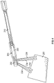
FIG. 1 depicts an optical probe excluding optical fibers; -
FIG. 2 depicts the optical probe shown inFIG. 1 including optical fibers; -
FIG. 3 depicts an optical probe performing an optical measurement on an airfoil; and -
FIG. 4 depicts an optical probe performing a measurement on an airfoil according to another non-limiting embodiment. - A detailed description of one or more embodiments of the disclosed apparatus and method are presented herein by way of exemplification and not limitation with reference to the Figures.
- Gas turbine engines include a several airfoil (also referred to as blades). The blades are susceptible to deflection during turbine engine operation, for example due to inlet compression or combustion gas transients or steam backpressure. Various embodiments of the present disclosure provide an optical probe configured to perform optical measurements on one or more airfoils included in a gas turbine engine. The gas turbine engine can be included, for example, in an aircraft vehicle. In one or more non-limiting embodiments, the optical probe is configured to output first and second transmit signal beams and receive first and second of reflected signal beams. The first and second signal beams are spread from a lens in a V-shaped pattern so as to measure two different targeted locations, e.g., two different radial location on an airfoil. The two different radial locations can be referred to as an inboard target location and an outboard target location.
- The corresponding first and second reflected signal beams, e.g., the reflected inboard beam reflected from to the inboard location and the reflected outboard beam reflected from the outboard location can be analyzed (e.g., by a controller) to determine characteristics of the airfoil such as, for example, airfoil deflection. For example, a time of arrival associated with the reflected inboard beam and the reflected outboard beam can be calculated and analyzed to determine deflection of the airfoil.
- With reference now to
FIG 1 , anoptical probe 200 is illustrated according to a non-limiting embodiment. The optical probe includes anoptical housing 202 extending from aproximate end 204 to an opposingdistal end 206. Although theoptical housing 202 is illustrated as extending in a substantially straight direction from theproximate end 204 to thedistal end 206, the profile of theoptical housing 202 is not limited thereto. For example, theoptical housing 202 can be rotated (e.g., 90 degrees), without departing from the scope of the inventive teachings described herein. - The
proximate end 204 includes asignal port 208 configured to receive asignal line 210 capable of communicating an optical signal. Thedistal end 206 includes a transmittinglens 212 and a receivinglens 214 that is separated from the transmittinglens 212. In some embodiments, the transmittinglens 212 and thereceiving lens 214 have the same diameter. In other embodiments, the transmittinglens 212 has a first lens diameter (e.g., about 50 µm) and the receivinglens 214 has second lens diameter (e.g., 200 µm) that is larger the transmittinglens 212. Various lens types can be employed as the transmittinglens 212 and the receivinglens 214 including, but not limiting to, a graded index of refraction (GrIn) lenses. - The
optical housing 202 has formed therein a transmittingoptical channel 216 and a receivingoptical channel 218 separated from the transmittingoptical channel 216. The transmittingoptical channel 216 extends from a transmittingchannel input 222 to a transmittingchannel output 224. The transmittingchannel input 222 is in signal communication with thesignal port 208 to receive an input optical signal from thesignal line 210. The transmittingchannel output 224 is in signal communication with the transmittinglens 212. The receivingoptical channel 218 extends from a receivingchannel input 226 to a receivingchannel output 228. The receivingchannel input 226 is in signal communication with the receivinglens 214 to receive a reflected optical signal. The receivingchannel output 228 is in signal communication with thesignal port 208 to deliver the reflected optical signal to thesignal line 210. - In one or more non-limiting embodiments, the
optical probe 200 includes one or more optical detectors 229. For example, a first optical detector 229 can be arranged in signal communication with the a first receivingoptical fiber 217 and a second optical detector 229 can be arranged in signal communication with the second receivingoptical fiber 219. The optical detectors 229 are configured to convert the reflected optical signals delivered by the respective receivingoptical fibers signal line 210 relays the electrical pulses to a controller, which performs time of arrival analysis corresponding to the reflected optical signals. Although the optical detectors 229 are illustrated as being disposed in thesignal port 208, the location of the optical detectors 229 is not limited thereto and can be place at various other locations allowing for signal communication with the receivingoptical fibers - Turning now to
FIG. 2 , theoptical probe 200 is shown installed withoptical fibers optical channel 216 has a first diameter and is configured to support a set of transmittingoptical fibers optical channel 218 has as second diameter and is configured to support a set of receivingoptical fibers optical fibers optical fibers optical fibers optical fibers optical fibers optical fibers optical fibers - The transmitting
lens 212 is configured to generate a set of transmitsignal beams optical fibers optical fibers optical channel 216 at different radial locations behind the transmittinglens 212 to generate the transmittingsignal beams lens 212 further spreads the output transmitsignal beams signal beams 230 and 232 (and consequently the reflected signal beams 234 and 236) can be determined a function of a variety of inputs, including but not limited to, lens diameter, fiber diameter, fiber numerical aperture, wavelength of transmitted/received light source, the index of refraction distribution function of the lens, and fiber-lens stand-off. - One or more non-limiting embodiments, the two different targeted locations are radial locations on an airfoil 201 (see
FIGS. 3 and4 ). The two different radial locations can be referred to as an inboard target location and an outboard target location. The receivinglens 214 is configured to receive a set of reflected signal beams 234 and 236, and direct them respectively to the receivingoptical fibers signal line 210. - The reflected beams 234 and 236 can be produced in response to the set of transmitting
signal beams airfoil 201 in a V-shaped pattern that is based, in part, on the locations of the inboard target location and an outboard target location. As described above, theoptical housing 202 can be rotated to extend at different angels (e.g., 90 degrees). In this manner, theoptical probe 200 can measure two different circumferential locations, rather than two different radial locations. - The
signal line 210 can be electrically connected to a controller (not shown) to establish data communication therebetween. The controller can perform a time of arrival analysis based on the set of transmitted optical signals and the set of reflected optical signals to determine characteristics of the airfoil including, but not limited, airfoil deflection. In one or more non-limiting embodiments, the time of arrival of two locations (e.g., an inboard location and an outboard location) on everyairfoil 201 on every revolution when the engine is running. The controller can compare the output from the optical detectors 229 to a voltage threshold to determine the precise time of arrival of a givenairfoil 201 associated with both thebeams - More specifically, the controller compares the times of arrival of the inboard location and the outboard location to determine if the outboard location (e.g., airfoil tip) arrives relatively earlier or later than the inboard location on each revolution. For Integral (or synchronous with engine speed) vibratory responses, there is a 180 degree phase shift in the vibratory phase of the blade at the measurement circumferential location when changing engine speed through a response (i.e. the engine is accelerating). Additionally, there will be a relative increase in vibratory deflection amplitude as the engine order driver and natural frequency converge at the crossing speed and a relative decrease in vibratory amplitude as these frequencies diverge. Using a single degree of freedom analysis, the controller can calculate the amplitude of the airfoil deflection, if any is present.
- The term "about" is intended to include the degree of error associated with measurement of the particular quantity based upon the equipment available at the time of filing the application. For example, "about" can include a range of ± 8% or 5%, or 2% of a given value.
- The terminology used herein is for the purpose of describing particular embodiments only and is not intended to be limiting of the present disclosure. As used herein, the singular forms "a", "an" and "the" are intended to include the plural forms as well, unless the context clearly indicates otherwise. It will be further understood that the terms "comprises" and/or "comprising," when used in this specification, specify the presence of stated features, integers, steps, operations, elements, and/or components, but do not preclude the presence or addition of one or more other features, integers, steps, operations, element components, and/or groups thereof.
- While the present invention has been described with reference to an exemplary embodiment or embodiments, it will be understood by those skilled in the art that various changes may be made and equivalents may be substituted for elements thereof without departing from the scope of the present disclosure as defined by the claims. In addition, many modifications may be made to adapt a particular situation or material to the teachings of the present disclosure without departing from the scope of the claims. Therefore, it is intended that the present invention not be limited to the particular embodiment disclosed as the best mode contemplated for carrying out this present invention, but that the present invention will include all embodiments falling within the scope of the claims.
Claims (15)
- An optical probe (200) comprising:an optical housing (202) extending from a proximate end (204) to an opposing distal end (206);a transmitting lens (212) disposed at the distal end and configured to output a first transmitted signal beam (230) having a first transmission axis and a second transmitted signal beam (232) having a second transmission axis, the first transmission axis and the second transmission axis being different; anda receiving lens (214) disposed at the distal end and configured to receive first and second reflected signal beams (234, 236) corresponding respectively to the first and second transmitted signal beams,wherein the optical housing has formed therein a transmitting optical channel (216) configured to communicate an input optical signal from the proximate end (204) to the transmitting lens (212), and a receiving optical channel (218) separated from the transmitting optical channel to communicate the first and second reflected signal beams to the proximate end.
- The optical probe of claim 1, wherein the transmitting optical channel (216) extends from a transmitting channel input (222) to a transmitting channel output (224), and wherein the receiving optical channel (218) extends from a receiving channel input (226) to a receiving channel output (228).
- The optical probe of claim 2, wherein the transmitting channel input (222) is in signal communication with a signal port (208) to receive an input optical signal from a signal line (210), and the transmitting channel output (224) is in signal communication with the transmitting lens (212).
- The optical probe of claim 3, wherein the receiving channel input (226) is in signal communication with the receiving lens (214) to receive the first and second reflected signal beams (234, 236), and the receiving channel output (228) is in signal communication with the signal port (208) to deliver the first and second reflected signal beams to the signal line (210).
- The optical probe of any preceding claim, further comprising at least one transmitting optical fiber (213, 215) disposed in the transmitting channel (216) and at least one receiving optical fiber (217, 219) disposed in the receiving channel (218).
- The optical probe of claim 5, wherein the at least one transmitting optical fiber includes first and second transmitting optical fibers (213, 215) positioned in the transmitting optical channel (216) at different radial locations behind the transmitting lens (212).
- The optical probe of claim 5 or 6, wherein the at least one receiving optical fiber includes first and second receiving optical fibers (217, 219) positioned in the receiving optical channel (218) at different radial locations behind the receiving lens (214).
- The optical probe of claim 5, 6, or 7, wherein the at least one transmitting optical fiber (213, 215) has a first diameter and the at least one receiving optical fiber (217, 219) has a second diameter that is larger than the first diameter; optionally wherein the transmitting lens (212) has a first lens diameter, the receiving lens (214) has a second lens diameter that is greater than the first lens diameter.
- The optical probe of any preceding claim, wherein the pair of transmitting signal beams (230, 232) is spread from the transmitting lens (212) at an angle to define a V-shaped pattern so as to measure two different targeted locations; optionally
wherein the angle ranges from about 1 degree to about 41 degrees. - The optical probe of claim 9, wherein the receiving lens (214) is configured to receive the first and second reflected signal beams (234, 236) produced in response to the first and second transmitting signal beams (230, 232) reflecting from respective target locations.
- A method of detecting a deflection in an airfoil (201), the method comprising:generating an input optical signal and transmitting the input optical signal from a proximate end (204) of an optical probe (200) to a distal end (206) of the optical probe via an optical channel (216);outputting first and second transmitted signal beams (230, 232) in response to delivering the input optical signal through a transmitting lens (212) disposed at a distal end of the optical probe; andreflecting the transmitted signal beams from the airfoil (201) to produce first and second reflected signal beams (234, 236);receiving the first and second reflected signal beams by a receiving lens (214) disposed at the distal end (206) of the optical probe (200); anddetermining the deflection of the airfoil based on the first and second reflected signal beams.
- The method of claim 11, wherein transmitting the input optical signal further comprises transmitting the input optical signal along at least one transmitting optical fiber (213, 215) disposed in a transmitting channel (216); optionally
wherein the at least one transmitting optical fiber (213, 215) includes first and second transmitting optical fibers positioned in the transmitting optical channel (216) at different radial locations behind the transmitting lens (212). - The method of claim 11 or 12, wherein receiving the first and second reflected signal beams (234, 236) further comprises transmitting the first and second reflected signals along at least one receiving optical fiber (217, 219) disposed in a receiving channel (218); optionally
wherein the at least one receiving optical fiber (217, 219) includes first and second receiving optical fibers positioned in the receiving optical channel (218) at different radial locations behind the receiving lens (214). - The method of claim 11, 12, or 13, wherein outputting the first and second transmitted signal beams (230, 232) further comprises spreading the first and second transmitted signal beams from the transmitting lens (212) in a V-shaped pattern so as to measure two different targeted locations; optionally
wherein receiving the first and second reflected signal beams (234, 236) further comprises receiving the first and second reflected signal beams in response to the first and second transmitting signal beams (230, 232) reflecting from the target locations. - The method of any of claims 11 to 14, further comprising converting the first and second reflected signals (234, 236) into electrical pulses, and determining the deflection based on the reflected signals.
Applications Claiming Priority (1)
| Application Number | Priority Date | Filing Date | Title |
|---|---|---|---|
| US17/063,028 US11714195B2 (en) | 2020-10-05 | 2020-10-05 | Optical time of arrival airfoil measurement probe |
Publications (2)
| Publication Number | Publication Date |
|---|---|
| EP3978893A1 true EP3978893A1 (en) | 2022-04-06 |
| EP3978893B1 EP3978893B1 (en) | 2023-05-10 |
Family
ID=78414179
Family Applications (1)
| Application Number | Title | Priority Date | Filing Date |
|---|---|---|---|
| EP21201020.1A Active EP3978893B1 (en) | 2020-10-05 | 2021-10-05 | Optical probe for airfoil deflection detection |
Country Status (2)
| Country | Link |
|---|---|
| US (1) | US11714195B2 (en) |
| EP (1) | EP3978893B1 (en) |
Citations (5)
| Publication number | Priority date | Publication date | Assignee | Title |
|---|---|---|---|---|
| US5557099A (en) * | 1993-12-24 | 1996-09-17 | Mtu Motoren- Und Turbinen-Union Muenchen Gmbh | Signal device for turbo-engines using an optical probe with an elliptical shaped light beam |
| EP1797813A1 (en) * | 2005-12-13 | 2007-06-20 | Siemens Aktiengesellschaft | Optical measuring device for measuring a hollow space |
| US20100171956A1 (en) * | 2009-01-07 | 2010-07-08 | Zolo Technologies, Inc. | Alignment Free Single-Ended Optical Probe and Methods for Spectroscopic Measurements in a Gas Turbine Engine |
| US20140268100A1 (en) * | 2013-03-15 | 2014-09-18 | United Technologies Corporation | Multiple Laser Time of Arrival Probe |
| WO2014143295A1 (en) * | 2013-03-15 | 2014-09-18 | United Technologies Corporation | Focused focused optical configuration for nsms probes |
Family Cites Families (22)
| Publication number | Priority date | Publication date | Assignee | Title |
|---|---|---|---|---|
| GB2066449B (en) * | 1979-12-21 | 1984-03-21 | Rolls Royce | Monitoring distance variations |
| US4708474A (en) | 1985-11-14 | 1987-11-24 | United Technologies Corporation | Reflection corrected radiosity optical pyrometer |
| US4657386A (en) | 1985-11-14 | 1987-04-14 | United Technologies Corporation | In-flight engine control optical pyrometer |
| US4666297A (en) | 1985-11-14 | 1987-05-19 | United Technologies Corporation | Dual spectra optical pyrometer having an air pressure sensitive shutter |
| US4696544A (en) | 1985-11-18 | 1987-09-29 | Olympus Corporation | Fiberscopic device for inspection of internal sections of construction, and method for using same |
| JP2937545B2 (en) * | 1991-05-30 | 1999-08-23 | 株式会社東芝 | Shaft vibrometer |
| WO2007115314A2 (en) | 2006-04-04 | 2007-10-11 | The Spectranetics Corporation | Laser-assisted guidewire having a variable stiffness shaft |
| US8451459B2 (en) | 2008-10-31 | 2013-05-28 | General Electric Company | Method and system for inspecting blade tip clearance |
| US8256297B2 (en) | 2010-01-05 | 2012-09-04 | General Electric Company | Systems and methods for measuring turbine blade vibratory response |
| FR2990754B1 (en) | 2012-05-15 | 2015-06-05 | Snecma | DEVICE FOR MEASURING THE VIBRATORY AMPLITUDES OF THE AUBES IN A TURBOMACHINE |
| US20140064924A1 (en) | 2012-08-30 | 2014-03-06 | Eli Cole Warren | Tip clearance probe for turbine applications |
| US9181818B2 (en) | 2012-09-25 | 2015-11-10 | United Technologies Corporation | Thermally constrained high temperature optical fiber holder |
| US9297720B2 (en) | 2012-12-21 | 2016-03-29 | United Technologies Corporation | Gas turbine engine vane embedded beam interrupt optical tip-timing probe system |
| US9366586B2 (en) | 2013-03-14 | 2016-06-14 | United Technologies Corporation | High temperature uncooled optical probe |
| US10365167B2 (en) | 2013-11-08 | 2019-07-30 | United Technologies Corporation | Fiber grating temperature sensor |
| US9988929B2 (en) | 2015-01-06 | 2018-06-05 | United Technologies Corporation | Borescope plug for gas turbine engine |
| GB2541689B (en) | 2015-08-26 | 2020-04-15 | Rolls Royce Plc | Apparatus and methods for determining location of at least a part of an object |
| JP6712845B2 (en) | 2015-09-10 | 2020-06-24 | 三菱日立パワーシステムズ株式会社 | Optical fiber probe, optical fiber measuring device and clearance control system |
| EP3327405A1 (en) | 2016-11-29 | 2018-05-30 | Siemens Aktiengesellschaft | Fibre optic sensor device |
| US10703854B2 (en) | 2017-12-05 | 2020-07-07 | Raytheon Technologies Corporation | Epoxy formula for integral capacitance probe |
| US10557373B2 (en) | 2017-12-05 | 2020-02-11 | United Technologies Corporation | Low profile embedded blade tip clearance probe assembly |
| US11686577B2 (en) | 2018-09-20 | 2023-06-27 | Raytheon Technologies Corporation | Anti-rotation method for angled face cap probe |
-
2020
- 2020-10-05 US US17/063,028 patent/US11714195B2/en active Active
-
2021
- 2021-10-05 EP EP21201020.1A patent/EP3978893B1/en active Active
Patent Citations (5)
| Publication number | Priority date | Publication date | Assignee | Title |
|---|---|---|---|---|
| US5557099A (en) * | 1993-12-24 | 1996-09-17 | Mtu Motoren- Und Turbinen-Union Muenchen Gmbh | Signal device for turbo-engines using an optical probe with an elliptical shaped light beam |
| EP1797813A1 (en) * | 2005-12-13 | 2007-06-20 | Siemens Aktiengesellschaft | Optical measuring device for measuring a hollow space |
| US20100171956A1 (en) * | 2009-01-07 | 2010-07-08 | Zolo Technologies, Inc. | Alignment Free Single-Ended Optical Probe and Methods for Spectroscopic Measurements in a Gas Turbine Engine |
| US20140268100A1 (en) * | 2013-03-15 | 2014-09-18 | United Technologies Corporation | Multiple Laser Time of Arrival Probe |
| WO2014143295A1 (en) * | 2013-03-15 | 2014-09-18 | United Technologies Corporation | Focused focused optical configuration for nsms probes |
Non-Patent Citations (1)
| Title |
|---|
| JONES H: "SHEDDING LIGHT ON VIBRATION", MECHANICAL ENGINEERING, ASME. NEW YORK, US, vol. 118, no. 11, 1 November 1996 (1996-11-01), pages 94 - 97, XP000643790, ISSN: 0025-6501 * |
Also Published As
| Publication number | Publication date |
|---|---|
| EP3978893B1 (en) | 2023-05-10 |
| US11714195B2 (en) | 2023-08-01 |
| US20220107416A1 (en) | 2022-04-07 |
Similar Documents
| Publication | Publication Date | Title |
|---|---|---|
| US8164761B2 (en) | Differential focus blade clearance probe and methods for using same | |
| JP5259568B2 (en) | System and method for direct non-intrusive measurement of corrected air flow | |
| EP1751581B1 (en) | Doppler radar sensing system for monitoring turbine generator components | |
| US8096184B2 (en) | Turbine blade for monitoring blade vibration | |
| US10458273B2 (en) | Blade vibration monitor with self adjusting sensor gap mechanism | |
| EP2936096B1 (en) | Traversing time of arrival probe | |
| CN104697798A (en) | System and method for three-dimensional characterization of blade tip gaps and dynamic detection of optical fibers of aero-engine | |
| US7027166B2 (en) | Method for measurement of the distance between a component which is moved past a reference surface and that reference surface, and a measurement system for carrying out the method | |
| CN112129400A (en) | A device and method for measuring blade tip timing based on fiber optic beam probe | |
| EP3978893B1 (en) | Optical probe for airfoil deflection detection | |
| US20130298686A1 (en) | Device and method for monitoring a rotor | |
| US12050152B2 (en) | Multi-mode microwave waveguide blade sensing system | |
| US9404735B2 (en) | Multiple laser time of arrival probe | |
| EP2972218B1 (en) | Focused optical configuration for nsms probes | |
| Fernández et al. | Analysis of the shaft behaviour in aircraft engines using tip clearance data and custom designed laser sensors | |
| CN211777611U (en) | Device for measuring synchronous vibration and pitch diameter of shrouded blade | |
| CN107402134B (en) | Rotating machinery tach signal based on hole inspecting hole synchronizes detecting system | |
| JP7288871B2 (en) | Steam turbine droplet measuring method and steam turbine droplet measuring device | |
| EP2574734B1 (en) | Systems and methods for mode shape identification | |
| Mineev et al. | Mathematical simulation of signal transmissionprocess in the optical assembly of a displacementmeasuring system | |
| Ross et al. | High-temperature high-precision casing-mounted optical sensors for in-situ measurement of blade vibration in rotating turbo machinery | |
| CN120489321A (en) | Light bending type low-pressure turbine shrouded blade tip timing sensor |
Legal Events
| Date | Code | Title | Description |
|---|---|---|---|
| PUAI | Public reference made under article 153(3) epc to a published international application that has entered the european phase |
Free format text: ORIGINAL CODE: 0009012 |
|
| STAA | Information on the status of an ep patent application or granted ep patent |
Free format text: STATUS: THE APPLICATION HAS BEEN PUBLISHED |
|
| AK | Designated contracting states |
Kind code of ref document: A1 Designated state(s): AL AT BE BG CH CY CZ DE DK EE ES FI FR GB GR HR HU IE IS IT LI LT LU LV MC MK MT NL NO PL PT RO RS SE SI SK SM TR |
|
| STAA | Information on the status of an ep patent application or granted ep patent |
Free format text: STATUS: REQUEST FOR EXAMINATION WAS MADE |
|
| 17P | Request for examination filed |
Effective date: 20221004 |
|
| RBV | Designated contracting states (corrected) |
Designated state(s): AL AT BE BG CH CY CZ DE DK EE ES FI FR GB GR HR HU IE IS IT LI LT LU LV MC MK MT NL NO PL PT RO RS SE SI SK SM TR |
|
| GRAP | Despatch of communication of intention to grant a patent |
Free format text: ORIGINAL CODE: EPIDOSNIGR1 |
|
| STAA | Information on the status of an ep patent application or granted ep patent |
Free format text: STATUS: GRANT OF PATENT IS INTENDED |
|
| INTG | Intention to grant announced |
Effective date: 20221212 |
|
| GRAS | Grant fee paid |
Free format text: ORIGINAL CODE: EPIDOSNIGR3 |
|
| GRAA | (expected) grant |
Free format text: ORIGINAL CODE: 0009210 |
|
| STAA | Information on the status of an ep patent application or granted ep patent |
Free format text: STATUS: THE PATENT HAS BEEN GRANTED |
|
| AK | Designated contracting states |
Kind code of ref document: B1 Designated state(s): AL AT BE BG CH CY CZ DE DK EE ES FI FR GB GR HR HU IE IS IT LI LT LU LV MC MK MT NL NO PL PT RO RS SE SI SK SM TR |
|
| REG | Reference to a national code |
Ref country code: GB Ref legal event code: FG4D |
|
| REG | Reference to a national code |
Ref country code: AT Ref legal event code: REF Ref document number: 1567130 Country of ref document: AT Kind code of ref document: T Effective date: 20230515 Ref country code: CH Ref legal event code: EP |
|
| REG | Reference to a national code |
Ref country code: DE Ref legal event code: R096 Ref document number: 602021002320 Country of ref document: DE |
|
| REG | Reference to a national code |
Ref country code: IE Ref legal event code: FG4D |
|
| P01 | Opt-out of the competence of the unified patent court (upc) registered |
Effective date: 20230603 |
|
| REG | Reference to a national code |
Ref country code: LT Ref legal event code: MG9D |
|
| REG | Reference to a national code |
Ref country code: NL Ref legal event code: MP Effective date: 20230510 |
|
| REG | Reference to a national code |
Ref country code: AT Ref legal event code: MK05 Ref document number: 1567130 Country of ref document: AT Kind code of ref document: T Effective date: 20230510 |
|
| PG25 | Lapsed in a contracting state [announced via postgrant information from national office to epo] |
Ref country code: SE Free format text: LAPSE BECAUSE OF FAILURE TO SUBMIT A TRANSLATION OF THE DESCRIPTION OR TO PAY THE FEE WITHIN THE PRESCRIBED TIME-LIMIT Effective date: 20230510 Ref country code: PT Free format text: LAPSE BECAUSE OF FAILURE TO SUBMIT A TRANSLATION OF THE DESCRIPTION OR TO PAY THE FEE WITHIN THE PRESCRIBED TIME-LIMIT Effective date: 20230911 Ref country code: NO Free format text: LAPSE BECAUSE OF FAILURE TO SUBMIT A TRANSLATION OF THE DESCRIPTION OR TO PAY THE FEE WITHIN THE PRESCRIBED TIME-LIMIT Effective date: 20230810 Ref country code: NL Free format text: LAPSE BECAUSE OF FAILURE TO SUBMIT A TRANSLATION OF THE DESCRIPTION OR TO PAY THE FEE WITHIN THE PRESCRIBED TIME-LIMIT Effective date: 20230510 Ref country code: ES Free format text: LAPSE BECAUSE OF FAILURE TO SUBMIT A TRANSLATION OF THE DESCRIPTION OR TO PAY THE FEE WITHIN THE PRESCRIBED TIME-LIMIT Effective date: 20230510 Ref country code: AT Free format text: LAPSE BECAUSE OF FAILURE TO SUBMIT A TRANSLATION OF THE DESCRIPTION OR TO PAY THE FEE WITHIN THE PRESCRIBED TIME-LIMIT Effective date: 20230510 |
|
| RAP4 | Party data changed (patent owner data changed or rights of a patent transferred) |
Owner name: RTX CORPORATION |
|
| PG25 | Lapsed in a contracting state [announced via postgrant information from national office to epo] |
Ref country code: RS Free format text: LAPSE BECAUSE OF FAILURE TO SUBMIT A TRANSLATION OF THE DESCRIPTION OR TO PAY THE FEE WITHIN THE PRESCRIBED TIME-LIMIT Effective date: 20230510 Ref country code: PL Free format text: LAPSE BECAUSE OF FAILURE TO SUBMIT A TRANSLATION OF THE DESCRIPTION OR TO PAY THE FEE WITHIN THE PRESCRIBED TIME-LIMIT Effective date: 20230510 Ref country code: LV Free format text: LAPSE BECAUSE OF FAILURE TO SUBMIT A TRANSLATION OF THE DESCRIPTION OR TO PAY THE FEE WITHIN THE PRESCRIBED TIME-LIMIT Effective date: 20230510 Ref country code: LT Free format text: LAPSE BECAUSE OF FAILURE TO SUBMIT A TRANSLATION OF THE DESCRIPTION OR TO PAY THE FEE WITHIN THE PRESCRIBED TIME-LIMIT Effective date: 20230510 Ref country code: IS Free format text: LAPSE BECAUSE OF FAILURE TO SUBMIT A TRANSLATION OF THE DESCRIPTION OR TO PAY THE FEE WITHIN THE PRESCRIBED TIME-LIMIT Effective date: 20230910 Ref country code: HR Free format text: LAPSE BECAUSE OF FAILURE TO SUBMIT A TRANSLATION OF THE DESCRIPTION OR TO PAY THE FEE WITHIN THE PRESCRIBED TIME-LIMIT Effective date: 20230510 Ref country code: GR Free format text: LAPSE BECAUSE OF FAILURE TO SUBMIT A TRANSLATION OF THE DESCRIPTION OR TO PAY THE FEE WITHIN THE PRESCRIBED TIME-LIMIT Effective date: 20230811 |
|
| PG25 | Lapsed in a contracting state [announced via postgrant information from national office to epo] |
Ref country code: FI Free format text: LAPSE BECAUSE OF FAILURE TO SUBMIT A TRANSLATION OF THE DESCRIPTION OR TO PAY THE FEE WITHIN THE PRESCRIBED TIME-LIMIT Effective date: 20230510 |
|
| PG25 | Lapsed in a contracting state [announced via postgrant information from national office to epo] |
Ref country code: SK Free format text: LAPSE BECAUSE OF FAILURE TO SUBMIT A TRANSLATION OF THE DESCRIPTION OR TO PAY THE FEE WITHIN THE PRESCRIBED TIME-LIMIT Effective date: 20230510 |
|
| PG25 | Lapsed in a contracting state [announced via postgrant information from national office to epo] |
Ref country code: SM Free format text: LAPSE BECAUSE OF FAILURE TO SUBMIT A TRANSLATION OF THE DESCRIPTION OR TO PAY THE FEE WITHIN THE PRESCRIBED TIME-LIMIT Effective date: 20230510 Ref country code: SK Free format text: LAPSE BECAUSE OF FAILURE TO SUBMIT A TRANSLATION OF THE DESCRIPTION OR TO PAY THE FEE WITHIN THE PRESCRIBED TIME-LIMIT Effective date: 20230510 Ref country code: RO Free format text: LAPSE BECAUSE OF FAILURE TO SUBMIT A TRANSLATION OF THE DESCRIPTION OR TO PAY THE FEE WITHIN THE PRESCRIBED TIME-LIMIT Effective date: 20230510 Ref country code: EE Free format text: LAPSE BECAUSE OF FAILURE TO SUBMIT A TRANSLATION OF THE DESCRIPTION OR TO PAY THE FEE WITHIN THE PRESCRIBED TIME-LIMIT Effective date: 20230510 Ref country code: DK Free format text: LAPSE BECAUSE OF FAILURE TO SUBMIT A TRANSLATION OF THE DESCRIPTION OR TO PAY THE FEE WITHIN THE PRESCRIBED TIME-LIMIT Effective date: 20230510 Ref country code: CZ Free format text: LAPSE BECAUSE OF FAILURE TO SUBMIT A TRANSLATION OF THE DESCRIPTION OR TO PAY THE FEE WITHIN THE PRESCRIBED TIME-LIMIT Effective date: 20230510 |
|
| REG | Reference to a national code |
Ref country code: DE Ref legal event code: R097 Ref document number: 602021002320 Country of ref document: DE |
|
| PLBE | No opposition filed within time limit |
Free format text: ORIGINAL CODE: 0009261 |
|
| STAA | Information on the status of an ep patent application or granted ep patent |
Free format text: STATUS: NO OPPOSITION FILED WITHIN TIME LIMIT |
|
| 26N | No opposition filed |
Effective date: 20240213 |
|
| PG25 | Lapsed in a contracting state [announced via postgrant information from national office to epo] |
Ref country code: SI Free format text: LAPSE BECAUSE OF FAILURE TO SUBMIT A TRANSLATION OF THE DESCRIPTION OR TO PAY THE FEE WITHIN THE PRESCRIBED TIME-LIMIT Effective date: 20230510 |
|
| PG25 | Lapsed in a contracting state [announced via postgrant information from national office to epo] |
Ref country code: SI Free format text: LAPSE BECAUSE OF FAILURE TO SUBMIT A TRANSLATION OF THE DESCRIPTION OR TO PAY THE FEE WITHIN THE PRESCRIBED TIME-LIMIT Effective date: 20230510 Ref country code: IT Free format text: LAPSE BECAUSE OF FAILURE TO SUBMIT A TRANSLATION OF THE DESCRIPTION OR TO PAY THE FEE WITHIN THE PRESCRIBED TIME-LIMIT Effective date: 20230510 Ref country code: MC Free format text: LAPSE BECAUSE OF FAILURE TO SUBMIT A TRANSLATION OF THE DESCRIPTION OR TO PAY THE FEE WITHIN THE PRESCRIBED TIME-LIMIT Effective date: 20230510 |
|
| REG | Reference to a national code |
Ref country code: BE Ref legal event code: MM Effective date: 20231031 |
|
| PG25 | Lapsed in a contracting state [announced via postgrant information from national office to epo] |
Ref country code: LU Free format text: LAPSE BECAUSE OF NON-PAYMENT OF DUE FEES Effective date: 20231005 |
|
| PG25 | Lapsed in a contracting state [announced via postgrant information from national office to epo] |
Ref country code: LU Free format text: LAPSE BECAUSE OF NON-PAYMENT OF DUE FEES Effective date: 20231005 |
|
| PG25 | Lapsed in a contracting state [announced via postgrant information from national office to epo] |
Ref country code: BE Free format text: LAPSE BECAUSE OF NON-PAYMENT OF DUE FEES Effective date: 20231031 |
|
| PG25 | Lapsed in a contracting state [announced via postgrant information from national office to epo] |
Ref country code: IE Free format text: LAPSE BECAUSE OF NON-PAYMENT OF DUE FEES Effective date: 20231005 |
|
| PG25 | Lapsed in a contracting state [announced via postgrant information from national office to epo] |
Ref country code: IE Free format text: LAPSE BECAUSE OF NON-PAYMENT OF DUE FEES Effective date: 20231005 |
|
| PG25 | Lapsed in a contracting state [announced via postgrant information from national office to epo] |
Ref country code: BG Free format text: LAPSE BECAUSE OF FAILURE TO SUBMIT A TRANSLATION OF THE DESCRIPTION OR TO PAY THE FEE WITHIN THE PRESCRIBED TIME-LIMIT Effective date: 20230510 |
|
| PG25 | Lapsed in a contracting state [announced via postgrant information from national office to epo] |
Ref country code: BG Free format text: LAPSE BECAUSE OF FAILURE TO SUBMIT A TRANSLATION OF THE DESCRIPTION OR TO PAY THE FEE WITHIN THE PRESCRIBED TIME-LIMIT Effective date: 20230510 |
|
| REG | Reference to a national code |
Ref country code: CH Ref legal event code: PL |
|
| PG25 | Lapsed in a contracting state [announced via postgrant information from national office to epo] |
Ref country code: CH Free format text: LAPSE BECAUSE OF NON-PAYMENT OF DUE FEES Effective date: 20241031 |
|
| PG25 | Lapsed in a contracting state [announced via postgrant information from national office to epo] |
Ref country code: CY Free format text: LAPSE BECAUSE OF FAILURE TO SUBMIT A TRANSLATION OF THE DESCRIPTION OR TO PAY THE FEE WITHIN THE PRESCRIBED TIME-LIMIT; INVALID AB INITIO Effective date: 20211005 |
|
| PG25 | Lapsed in a contracting state [announced via postgrant information from national office to epo] |
Ref country code: HU Free format text: LAPSE BECAUSE OF FAILURE TO SUBMIT A TRANSLATION OF THE DESCRIPTION OR TO PAY THE FEE WITHIN THE PRESCRIBED TIME-LIMIT; INVALID AB INITIO Effective date: 20211005 |
|
| REG | Reference to a national code |
Ref country code: DE Ref legal event code: R081 Ref document number: 602021002320 Country of ref document: DE Owner name: RTX CORPORATION (N.D.GES.D. STAATES DELAWARE),, US Free format text: FORMER OWNER: RAYTHEON TECHNOLOGIES CORPORATION, FARMINGTON, CT, US |
|
| PGFP | Annual fee paid to national office [announced via postgrant information from national office to epo] |
Ref country code: GB Payment date: 20250923 Year of fee payment: 5 |
|
| PGFP | Annual fee paid to national office [announced via postgrant information from national office to epo] |
Ref country code: FR Payment date: 20250923 Year of fee payment: 5 |
|
| PG25 | Lapsed in a contracting state [announced via postgrant information from national office to epo] |
Ref country code: TR Free format text: LAPSE BECAUSE OF FAILURE TO SUBMIT A TRANSLATION OF THE DESCRIPTION OR TO PAY THE FEE WITHIN THE PRESCRIBED TIME-LIMIT Effective date: 20230510 |
|
| PGFP | Annual fee paid to national office [announced via postgrant information from national office to epo] |
Ref country code: DE Payment date: 20250923 Year of fee payment: 5 |