EP3978871B1 - Low range altimeter active leakage cancellation - Google Patents
Low range altimeter active leakage cancellation Download PDFInfo
- Publication number
- EP3978871B1 EP3978871B1 EP21199823.2A EP21199823A EP3978871B1 EP 3978871 B1 EP3978871 B1 EP 3978871B1 EP 21199823 A EP21199823 A EP 21199823A EP 3978871 B1 EP3978871 B1 EP 3978871B1
- Authority
- EP
- European Patent Office
- Prior art keywords
- signal
- antenna
- lra
- leakage
- receiver
- Prior art date
- Legal status (The legal status is an assumption and is not a legal conclusion. Google has not performed a legal analysis and makes no representation as to the accuracy of the status listed.)
- Active
Links
Images


Classifications
-
- G—PHYSICS
- G01—MEASURING; TESTING
- G01S—RADIO DIRECTION-FINDING; RADIO NAVIGATION; DETERMINING DISTANCE OR VELOCITY BY USE OF RADIO WAVES; LOCATING OR PRESENCE-DETECTING BY USE OF THE REFLECTION OR RERADIATION OF RADIO WAVES; ANALOGOUS ARRANGEMENTS USING OTHER WAVES
- G01S13/00—Systems using the reflection or reradiation of radio waves, e.g. radar systems; Analogous systems using reflection or reradiation of waves whose nature or wavelength is irrelevant or unspecified
- G01S13/88—Radar or analogous systems specially adapted for specific applications
- G01S13/882—Radar or analogous systems specially adapted for specific applications for altimeters
-
- G—PHYSICS
- G01—MEASURING; TESTING
- G01C—MEASURING DISTANCES, LEVELS OR BEARINGS; SURVEYING; NAVIGATION; GYROSCOPIC INSTRUMENTS; PHOTOGRAMMETRY OR VIDEOGRAMMETRY
- G01C5/00—Measuring height; Measuring distances transverse to line of sight; Levelling between separated points; Surveyors' levels
- G01C5/005—Measuring height; Measuring distances transverse to line of sight; Levelling between separated points; Surveyors' levels altimeters for aircraft
-
- G—PHYSICS
- G01—MEASURING; TESTING
- G01S—RADIO DIRECTION-FINDING; RADIO NAVIGATION; DETERMINING DISTANCE OR VELOCITY BY USE OF RADIO WAVES; LOCATING OR PRESENCE-DETECTING BY USE OF THE REFLECTION OR RERADIATION OF RADIO WAVES; ANALOGOUS ARRANGEMENTS USING OTHER WAVES
- G01S13/00—Systems using the reflection or reradiation of radio waves, e.g. radar systems; Analogous systems using reflection or reradiation of waves whose nature or wavelength is irrelevant or unspecified
- G01S13/02—Systems using reflection of radio waves, e.g. primary radar systems; Analogous systems
- G01S13/06—Systems determining position data of a target
- G01S13/08—Systems for measuring distance only
- G01S13/32—Systems for measuring distance only using transmission of continuous waves, whether amplitude-, frequency-, or phase-modulated, or unmodulated
-
- G—PHYSICS
- G01—MEASURING; TESTING
- G01S—RADIO DIRECTION-FINDING; RADIO NAVIGATION; DETERMINING DISTANCE OR VELOCITY BY USE OF RADIO WAVES; LOCATING OR PRESENCE-DETECTING BY USE OF THE REFLECTION OR RERADIATION OF RADIO WAVES; ANALOGOUS ARRANGEMENTS USING OTHER WAVES
- G01S7/00—Details of systems according to groups G01S13/00, G01S15/00, G01S17/00
- G01S7/02—Details of systems according to groups G01S13/00, G01S15/00, G01S17/00 of systems according to group G01S13/00
- G01S7/35—Details of non-pulse systems
- G01S7/352—Receivers
- G01S7/358—Receivers using I/Q processing
-
- G—PHYSICS
- G01—MEASURING; TESTING
- G01S—RADIO DIRECTION-FINDING; RADIO NAVIGATION; DETERMINING DISTANCE OR VELOCITY BY USE OF RADIO WAVES; LOCATING OR PRESENCE-DETECTING BY USE OF THE REFLECTION OR RERADIATION OF RADIO WAVES; ANALOGOUS ARRANGEMENTS USING OTHER WAVES
- G01S7/00—Details of systems according to groups G01S13/00, G01S15/00, G01S17/00
- G01S7/02—Details of systems according to groups G01S13/00, G01S15/00, G01S17/00 of systems according to group G01S13/00
- G01S7/40—Means for monitoring or calibrating
- G01S7/4004—Means for monitoring or calibrating of parts of a radar system
- G01S7/4008—Means for monitoring or calibrating of parts of a radar system of transmitters
-
- H—ELECTRICITY
- H01—ELECTRIC ELEMENTS
- H01Q—ANTENNAS, i.e. RADIO AERIALS
- H01Q1/00—Details of, or arrangements associated with, antennas
- H01Q1/52—Means for reducing coupling between antennas; Means for reducing coupling between an antenna and another structure
- H01Q1/521—Means for reducing coupling between antennas; Means for reducing coupling between an antenna and another structure reducing the coupling between adjacent antennas
- H01Q1/525—Means for reducing coupling between antennas; Means for reducing coupling between an antenna and another structure reducing the coupling between adjacent antennas between emitting and receiving antennas
Definitions
- a low range altimeter may be susceptible to leakage, which results in interference.
- the LRA may be non-integrated, including multiple antennas that are physically separated to address the leakage through isolation.
- the LRA may be integrated, including dual integrated antennas for the transmitters and receivers, respectively, that are physically separated to address the leakage through isolation.
- the LRA may be integrated, including a single antenna for both the transmitters and receivers that may require a duplexer solution for the leakage, due to being unable to be physically separated.
- Known integrated LRAs may not include antennas that are sufficiently physically separated to provide a necessary or desired level of isolation addressing the leakage, leading to issues caused by leakage being more severe in an integrated LRA due to the reduced physical separation.
- KR 2018 0110269 A discloses an FMCW radar apparatus, e.g. for use as an altimeter, featuring leakage signal elimination.
- the present invention provides for a low range altimeter (LRA) according to independent claim 1.
- LRA low range altimeter
- the at least one antenna may include a transmitting (TX) antenna coupled to the transmitter.
- the at least one antenna may include a receiving (RX) antenna coupled to the receiver. The leakage may be observed from the transmitting antenna by the receiving antenna.
- the at least one antenna may include a combination transmitting and receiving (TX/RX) antenna coupled to the transmitter and the receiver.
- TX/RX transmitting and receiving
- a radio frequency (RF) circulator-based duplexer positioned between the transmitter, the receiver, and the combination (TX/RX) antenna.
- the leakage may be observed through the RF circulator-based duplexer in addition to the received second signal.
- the adjustment to gain and phase may be synchronized with a frequency sweep of the signal.
- the active leakage cancellation circuit may include a vector modulator configured to adjust the in-phase and quadrature (I and Q) of the transmitted signal.
- the adjustment to I and Q may be controlled by the MCU in response to a determination made by the MCU based on the static leakage reading.
- the adjustment to I and Q may be synchronized with a frequency sweep of the signal.
- a letter following a reference numeral is intended to reference an embodiment of the feature or element that may be similar, but not necessarily identical, to a previously described element or feature bearing the same reference numeral (e.g., 1, 1a, 1b).
- reference numeral e.g. 1, 1a, 1b
- Such shorthand notations are used for purposes of convenience only and should not be construed to limit the disclosure in any way unless expressly stated to the contrary.
- any reference to “one embodiment” or “some embodiments” means that a particular element, feature, structure, or characteristic described in connection with the embodiment is included in at least one embodiment disclosed herein.
- the appearances of the phrase “in some embodiments” in various places in the specification are not necessarily all referring to the same embodiment, and embodiments may include one or more of the features expressly described or inherently present herein, or any combination of sub-combination of two or more such features, along with any other features which may not necessarily be expressly described or inherently present in the instant disclosure.
- FIGS. 1A-5 in general illustrate a low range altimeter (LRA) with active leakage cancellation.
- LRA low range altimeter
- FIGS. 1A-1C in general illustrate portions of an antenna assembly 100, in accordance with one or more embodiments of the disclosure.
- the antenna assembly 100 may be susceptible to leakage, which results in interference. Leakage may cause two issues, including a masking of low altitude returns and a masking of high altitude returns. For example, masking low altitude returns may cause spreading due to finite bandwidth. The masking of the low altitude returns may be addressed at least in part with post processing in software, being a static leakage term. By way of another example, masking high altitude returns may be caused by transmitter phase noise. The masking of the high altitude returns may not be cancelled with software.
- the antenna assembly 100 may be non-integrated, including a low range unit 102 (e.g., a housing) with a transmitter 104 and a receiver 106.
- the transmitter 104 may include a TX antenna 108 and the receiver 106 may include an RX antenna 110 outside of the low range unit 102 that are physically separated to address the leakage through isolation.
- Having multiple antennas may be, in part, to meet guidelines and/or standards set forth by, but not limited to, the Federal Aviation Administration (FAA), the European Aviation Safety Agency (EASA) or any other flight certification agency or organization; the American National Standards Institute (ANSI), Aeronautical Radio, Incorporated (ARINC), or any other standards setting organization or company; the Radio Technical Commission for Aeronautics (RTCA) or any other guidelines agency or organization; or the like.
- FAA Federal Aviation Administration
- EASA European Aviation Safety Agency
- ARINC Aeronautical Radio, Incorporated
- RTCA Radio Technical Commission for Aeronautics
- Frequency Modulated Continuous Wave (FMCW) radar altimeters may require high TX/RX isolation in order to prevent leakage paths from desensitizing the receiver due to finite transmitter phase noise and noise floor.
- TX/RX isolation in a Minimum Operational Performance Standards (MOPS) LRA installation may be at least 75 decibels (dB), which may be met by separating non-integrated antennas.
- the physical separation may create siting issues for the antenna and corresponding components on an aircraft, where multiple antennas are required and/or installed. For example, a requirement of six antennas and an operation frequency of 4.3 GHz may require a number of large radio frequency (RF) feeder cables and siting locations for the antenna on the aircraft.
- RF radio frequency
- an antenna assembly 100 may be integrated, with the TX antenna 108 and the RX antenna 110 also housed within the low range unit 102 in addition to the transmitter 104 and the receiver 106.
- the TX antenna 108 and the RX antenna 110 may be physically separated to address the leakage through isolation. Because of the integrated nature of the antenna assembly 100, however, the ability to isolate may be limited due to proximity, with a minimum isolation reaching only approximately between 30 and 40 dB.
- the antenna assembly 100 may be integrated, including an integrated single antenna 112, or combination transmitting and receiving (TX/RX) antenna 112, for both the transmitter 104 and the receiver 106.
- the antenna assembly 100 illustrated in FIG. 1C may include an RF circulator-based duplexer 114 between the transmitter 104 and the receiver 106.
- the RF circulator-based duplexer 114 may allow for transmitting of a signal from the transmitter 104 through the TX/RX antenna 112 and/or allow for the receiving of the signal via the receiver 106 from the TX/RX antenna 112.
- the integrated single antenna 112 may require a different solution for the leakage, due to being unable to be physically separated.
- Known integrated builds may not include antennas that are sufficiently physically separated to provide a necessary or desired level of isolation addressing the leakage, leading to issues caused by leakage being more severe in an integrated LRA due to the reduced physical separation.
- reducing the system sensitivity through isolation of the TX/RX antenna 112 in an integrated LRA build may be infeasible or may provide unacceptable performance degradation due to TX phase noise, even assuming an FMCW source with very low phase noise proximity, with a minimum isolation reaching only approximately 10 dB.
- the antenna assembly 100 being integrated is still desirable to be competitive in a market.
- the cost to manufacture and install may be greatly reduced.
- the integrated design may result in a smaller footprint allowing for installation on smaller aircraft, resulting in a safer aircraft and shared airspace.
- the integrating of the antenna assembly 100 with either an integrated dual antenna or an integrated single antenna would allow for all electronics related to the antenna assembly 100 to be mounted at a single location on an aircraft, including the removal of a number of radio frequency (RF) feeder cables and a number of other antenna from the antenna assembly 100, thus reducing cost, size, and need for multiple locations on the aircraft.
- the reduction of size and need for multiple locations on the aircraft may reduce installation issues on the aircraft (e.g., that might be present with dual or triple location installations).
- the antenna assembly 100 should include an active leakage cancellation circuit configured to inject an appropriate cancellation signal in the front of a receiver or receiver.
- a microcontroller unit (MCU) of the antenna assembly 100 should be configured to determine a gain and phase, and/or an in-phase and quadrature (I and Q), for the cancellation signal.
- the MCU of the antenna assembly 100 should be configured to adapt the cancellation signal at various points in the frequency sweep of the signal to reduce or cancel the leakage.
- the MCU of the antenna assembly 100 should be configured to synchronize the gain and phase adjustments with the frequency sweep of the signal.
- the MCU of the antenna assembly 100 should be configured to synchronize the I and Q adjustments with the frequency sweep of the signal.
- the antenna assembly 100 should include both a hardware component and a software component configured to mitigate the masking of low altitude returns and the masking of high altitude returns due to the leakage.
- FIGS. 2A-2D in general illustrate an integrated LRA 200 with an active leakage cancellation circuit 202.
- Fig.2C illustrates an embodiment of the present invention
- Figs.2A , 2B and 2D illustrate comparative examples.
- FIG. 2A illustrates an integrated dual antenna LRA 200.
- FIG. 2B illustrates an integrated single antenna LRA 200.
- active leakage cancellation circuit and variants including, but not limited to, “active cancellation circuit,” “cancellation circuit,” or the like may be considered equivalent, for purposes of the disclosure.
- the integrated LRA 200 may include an MCU 116.
- the MCU 116 may be coupled to the transmitter 104 and configured to transmit information via the transmitter 104.
- the MCU 116 may be coupled to the receiver 106 and configured to receive information via the receiver 106.
- the transmitter 104 may include a signal generator 118.
- the signal generator 118 may produce an FMCW signal.
- the signal generator 118 may produce any spread spectrum signal.
- the active cancellation circuit 202 may operate with any signal types and/or architecture known in the art.
- the transmitter 104 may include a power amplifier (PA) 120.
- the signal generator 118 may be coupled to the PA 120.
- the PA 120 may be directly coupled to the TX antenna 108, such that the PA 120 supplies the TX antenna 108 with a modified or unmodified portion of the signal from the signal generator 118.
- the PA 120 may be coupled to the RF circulator-based duplexer 114, which may in turn be coupled to the TX/RX antenna 112, such that the RF circulator-based duplexer 114 supplies the TX antenna 108 with a modified or unmodified portion of the signal from the signal generator 118.
- the receiver 106 may include a low-noise amplifier (LNA) 122.
- LNA low-noise amplifier
- the RX antenna 110 may be directly coupled to the LNA 122.
- the TX/RX antenna 112 may be coupled to the RF circulator-based duplexer 114, which may in turn be coupled to the LNA 122.
- the receiver 106 may include an intermediate frequency (IF) analog-to-digital converter (ADC) 124.
- the LNA 122 may be coupled to the ADC 124, such that the LNA 122 supplies the ADC 124 with a modified or unmodified portion of the signal from the RX antenna 108.
- IF intermediate frequency
- ADC analog-to-digital converter
- the receiver 106 and/or the transmitter 104 may include a frequency mixer 126. It is noted herein the frequency mixer 126 may be positioned at any location within the circuit(s) forming the receiver 106 and/or the transmitter 104.
- the active cancellation circuit 202 may include a digital-to-analog converter (DAC) 204.
- DAC digital-to-analog converter
- a first channel of the DAC 204 may be coupled to the MCU 116 and to a variable attenuator 206
- a second channel of the DAC 204 may be coupled to the MCU 116 and to a phase shifter 208.
- the variable attenuator 206 and the phase shifter 208 may be in series within the active cancellation circuit 202.
- the first and second channels of the DAC 204 may be coupled to the MCU 116 and the in-phase and quadrature (I and Q) inputs of a vector modulator 210, respectively.
- the vector modulator 210 may include a quadrature modulator or other orthogonal modulator. It is noted herein the active cancellation circuit 202 may include either or both of the variable attenuator 206 and the phase shifter 208, and the vector modulator 210.
- the integrated dual antenna LRA 200 may observe leakage between the TX antenna 108 and the RX antenna 110, instead of seeing only a (or any) reflection signal from the ground.
- the variable attenuator 206 and the phase shifter 208 (e.g., as illustrated in FIG. 2A ) and/or the vector modulator 210 (e.g., as illustrated in FIG 2B ) may exit the transmitter 104 behind the PA 120 at a node or location 212, and may enter the receiver 106 in front of the LNA 122 at a node or location 214.
- some amount of the transmitted signal may be fed directly from the transmitter 104 and to the receiver 106 to reduce or cancel the self-reading caused by leakage between the TX antenna 108 and the RX antenna 110.
- the integrated single antenna LRA 200 may have leakage passing from the transmitter 104, through the RF circulator-based duplexer 114, and directly into the receiver 106 in addition to the reflection signal from the ground received via the TX/RX antenna 112.
- the variable attenuator 206 and the phase shifter 208 (e.g., as illustrated in FIG. 2C ) and/or the vector modulator 210 (e.g., as illustrated in FIG. 2D ) may exit the transmitter 104 in front of the PA 120 at a node or location 216 and enter the receiver 106 in front of the LNA 122 at the node or location 214.
- the integrated single antenna LRA 200 may have a minimum isolation of only approximately 10 dB, as the isolating element in the integrated LRA 200 is largely the RF circulator-based duplexer 114. Due to this, the leakage signal may be too strong to be reduced or cancelled by just the variable attenuator 206 and the phase shifter 208, and/or the vector modulator 210.
- the active cancellation circuit 202 may include an additional amplifier 218 after the variable attenuator 206 and the phase shifter 208 and before the node or location 214.
- the additional amplifier 218 may be added to either the integrated single antenna LRA 200 or the integrated dual antenna LRA 200.
- Coupled to may mean one or more of “communicatively coupled to,” “electrically coupled to,” and/or “physically coupled to,” for purposes of the present disclosure.
- directions such as “behind” or “in front” may be understood to be relative to movement or flow of the signal within the transmitter 104 the receiver 106, and/or the active cancellation circuit 202.
- LRA 200 illustrates the LRA 200 as including one or more integrated antennas
- the active cancellation circuit 202 may be used with LRA 200 including non-integrated antennas (e.g., antennas outside the low range unit 102, as illustrated in FIG. 1A ). Therefore, the above description should not be interpreted as a limitation on the present disclosure but merely an illustration.
- FIG. 3 illustrates a method or process 300 for active cancellation of leakage in the integrated LRA 200, in accordance with one or more embodiments of the disclosure.
- FIG. 4 is a graph illustrating a comparison between a non-adapted signal and a resultant adapted signal adjusted with active leakage cancellation, in accordance with one or more embodiments of the disclosure.
- a static leakage reading may be measured from a receiver of an integrated LRA.
- the static leakage reading may be an output of the ADC 124 (e.g., as measured by the MCU 116).
- Line 402 of the graph 400, as illustrated in FIG. 4 is an example representation of the output of the ADC 124 prior to the active cancellation of the leakage.
- a portion of a transmit signal may be received by an active cancellation circuit. As illustrated in FIG. 2A , the portion of the transmitted signal from the transmitter 104 may be received behind the PA 120. As illustrated in FIG. 2B , the portion of the transmitted signal from the transmitter 104 may be received in front of the PA 120.
- one or more gain adjustments are determined.
- one or more phase adjustments are determined.
- the algorithm may receive the static leakage reading taken from the ADC 124 and determine one or more settings for the variable attenuator 206 and/or the phase shifter 208 based on the static leakage reading.
- the algorithm may receive the static leakage reading taken from the ADC 124 and determine one or more settings for the vector modulator210 based on the static leakage reading.
- the determination of the gain adjustments and/or the phase adjustments may be performed via the MCU 116.
- a step 310 the one or more gain adjustments are performed on the portion of the transmitted signal via a variable attenuator.
- the one or more phase adjustments are performed on the portion of the signal via a phase shifter.
- the MCU 116 may adjust an output of the active cancellation circuit 202 via the variable attenuator 206 and/or the phase shifter 208. In addition, or in the alternative, the MCU 116 may adjust an output of the active cancellation circuit 202 via the vector modulator 210.
- the adjusted portion of the transmitted signal is injected to the receiver of the integrated LRA.
- the MCU 116 may again measure the static leakage reading may be an output of the ADC 124 after the active cancellation of the leakage to confirm the cancellation and continue to monitor the receiver 106.
- Line 404 of the graph 400, as illustrated in FIG. 4 is an example representation of the output of the ADC 124 after the active cancellation of the leakage.
- the active cancellation of the leakage may occur during operation of the aircraft (e.g., on-the-fly).
- a look-up table may be employed at one or more stages of flight to assist in the leakage cancellation (e.g., as a starting point or calibration tool, or the like).
- a lookup table may require compensation for temperature to be determined, while the algorithm may not need the temperature compensation to adjust the reducing or cancelling the leakage signal. Therefore, the above description should not be interpreted as a limitation on the present disclosure but merely an illustration.
- the method or process 300 is not limited to the steps and/or sub-steps provided.
- the method or process 300 may include more or fewer steps and/or sub-steps.
- the method or process 300 may perform the steps and/or sub-steps simultaneously.
- the method or process 300 may perform the steps and/or sub-steps sequentially, including in the order provided or an order other than provided. Therefore, the above description should not be interpreted as a limitation on the scope of the disclosure but merely an illustration.
- FIG. 5 illustrates an aircraft 500 including the integrated LRA 200, in accordance with one or more embodiments of the disclosure.
- the MCU 116 may be coupled to a separate primary controller 502 installed within the aircraft 500.
- the MCU 116 may be a component within the integrated LRA 200, however, it is noted herein the functions and operations performed by the MCU 116 may be performed by the primary controller 502 within the aircraft 500. In this regard, the MCU 116 may not be necessary within the integrated LRA 200, and any embodiment directed to operations or functions by the MCU 116 may be also directed to the primary controller 502.
- the primary controller 502 may include one or more processors 504 configured to execute program instructions maintained on memory medium 506.
- the MCU 116 may include one or more processors 508 configured to execute program instructions maintained on memory medium 510.
- the one or more processors 504, 508 of the primary controller 502 or the MCU 116, respectively, may execute any of the various process steps described throughout the present disclosure.
- the one or more processors 504, 508 of a primary controller 502 or the MCU 116 may include any processor or processing element known in the art.
- the term "processor” or “processing element” may be broadly defined to encompass any device having one or more processing or logic elements (e.g., one or more micro-processor devices, one or more application specific integrated circuit (ASIC) devices, one or more field programmable gate arrays (FPGAs), or one or more digital signal processors (DSPs)).
- the one or more processors 504, 508 may include any device configured to execute algorithms and/or instructions (e.g., program instructions stored in memory).
- the one or more processors 504, 508 may be embodied as a desktop computer, mainframe computer system, workstation, image computer, parallel processor, networked computer, or any other computer system configured to execute a program configured to operate or operate in conjunction with the integrated LRA 200, as described throughout the present disclosure.
- different subsystems of the aircraft 500 may include a processor or logic elements suitable for carrying out at least a portion of the steps described in the present disclosure. Therefore, the above description should not be interpreted as a limitation on the embodiments of the present disclosure but merely as an illustration. Further, the steps described throughout the present disclosure may be carried out by a single primary controller 502 or the MCU 116, respectively or, alternatively, multiple controllers. In addition, the primary controller 502 or the MCU 116, respectively may include one or more controllers housed in a common housing or within multiple housings.
- any controller or combination of controllers may be separately packaged as a module suitable for integration into the defect detection system.
- the primary controller 502 or the MCU 116 respectively may analyze a signal received from the detector and feed the signal to additional components within the integrated LRA 200 or external to the integrated LRA 200.
- the memory medium 506, 510 may include any storage medium known in the art suitable for storing program instructions executable by the associated one or more processors 504, 508.
- the memory medium 506, 510 may include a non-transitory memory medium.
- the memory medium 506, 510 may include, but is not limited to, a read-only memory (ROM), a random-access memory (RAM), a magnetic or optical memory device (e.g., disk), a magnetic tape, a solid-state drive and the like. It is further noted that memory medium 506, 510 may be housed in a common controller housing with the one or more processors 504, 508.
- the memory medium 506, 510 may be located remotely with respect to the physical location of the one or more processors 504, 508 and primary controller 502 or the MCU 116, respectively.
- the one or more processors 504, 508 of primary controller 502 or the MCU 116 respectively may access a remote memory (e.g., server), accessible through a network (e.g., internet, intranet and the like).
- a remote memory e.g., server
- a network e.g., internet, intranet and the like.
- a user interface is communicatively coupled to the primary controller 502 or the MCU 116, respectively.
- the user interface may include, but is not limited to, one or more desktops, laptops, tablets, and the like.
- the user interface includes a display used to display data of the system 500 to a user.
- the display of the user interface may include any display known in the art.
- the display may include, but is not limited to, a liquid crystal display (LCD), an organic light-emitting diode (OLED) based display, or a CRT display.
- LCD liquid crystal display
- OLED organic light-emitting diode
- CRT display Those skilled in the art should recognize that any display device capable of integration with a user interface is suitable for implementation in the present disclosure.
- a user may input selections and/or instructions responsive to data displayed to the user via a user input device of the user interface.
- variable attenuator 206 and the phase shifter 208, and/or the vector modulator 210 may be manually adjustable by a user via a user input device (e.g., a toggle, switch, knob, or other user input device).
- a user input device e.g., a toggle, switch, knob, or other user input device.
- the user interface may display an adjustment to gain or phase determined based on the static leakage reading from the ADC 124, and the user may interact with the user input device to make the appropriate adjustments within the active cancellation circuit 202.
- the primary controller 502 or the MCU 116 respectively is communicatively coupled to one or more elements of the integrated LRA 200.
- the primary controller 502 or the MCU 116 respectively may transmit and/or receive data from any component of the integrated LRA 200.
- the primary controller 502 or the MCU 116 respectively may direct or otherwise control any component of the integrated LRA 200.
- the primary controller 502 or the MCU 116 may be programmed to execute an algorithm configured to constantly take a static leakage reading from the ADC 124, determine gain adjustments and/or phase adjustments to reduce or cancel leakage observed in the static leakage reading, and adjust an output of the active cancellation circuit 202 via the variable attenuator 206 and/or the phase shifter 208, and/or via the vector modulator 210, based on the determined gain adjustments and/or phase adjustments during operation of the aircraft.
- the integrated LRA 200 includes the active leakage cancellation circuit 202 configured to inject an appropriate cancellation signal in the front of a receiver or receiver 106.
- the MCU 116 of the integrated LRA 200 is configured to determine a gain and phase for the cancellation signal.
- the MCU of the integrated LRA 200 is configured to adapt the cancellation signal at various points in the frequency sweep of the signal to reduce or cancel the leakage.
- the MCU of the integrated LRA 200 is configured to synchronize the gain and phase adjustments with the frequency sweep of the signal.
- the integrated LRA 200 includes both a hardware component and a software component configured to mitigate the masking of low altitude returns and the masking of high altitude returns in the leakage.
- the integrated LRA 200 and/or components of the integrated LRA 200 are not limited to the aviation environment and/or the aircraft components within the aviation environment.
- the integrated LRA 200 and/or components of the integrated LRA 200 may be configured for any type of vehicle known in the art.
- the vehicle may be any air, space, land, or water-based personal equipment or vehicle; any air, space, land, or water-based commercial equipment or vehicle; any air, space, land, or water-based military equipment or vehicle known in the art.
- the integrated LRA 200 and/or components of the integrated LRA 200 may be configured for commercial or industrial use in either a home or a business. Therefore, the above description should not be interpreted as a limitation on the present disclosure but merely an illustration.
Landscapes
- Engineering & Computer Science (AREA)
- Radar, Positioning & Navigation (AREA)
- Remote Sensing (AREA)
- Physics & Mathematics (AREA)
- General Physics & Mathematics (AREA)
- Computer Networks & Wireless Communication (AREA)
- Electromagnetism (AREA)
- Transceivers (AREA)
Description
- A low range altimeter (LRA) may be susceptible to leakage, which results in interference. The LRA may be non-integrated, including multiple antennas that are physically separated to address the leakage through isolation. The LRA may be integrated, including dual integrated antennas for the transmitters and receivers, respectively, that are physically separated to address the leakage through isolation. The LRA may be integrated, including a single antenna for both the transmitters and receivers that may require a duplexer solution for the leakage, due to being unable to be physically separated. Known integrated LRAs may not include antennas that are sufficiently physically separated to provide a necessary or desired level of isolation addressing the leakage, leading to issues caused by leakage being more severe in an integrated LRA due to the reduced physical separation. Kaihui Lin et al, "Real-time dsp for reflected power cancellation in FMCW radars", 2004 IEEE 60th Vehicular Technology Conference, 26 September 2004 relates to leakage cancellation in monostatic FMCW radars.
KR 2018 0110269 A - The present invention provides for a low range altimeter (LRA) according to
independent claim 1. - In some embodiments, the at least one antenna may include a transmitting (TX) antenna coupled to the transmitter. The at least one antenna may include a receiving (RX) antenna coupled to the receiver. The leakage may be observed from the transmitting antenna by the receiving antenna.
- In some embodiments, the at least one antenna may include a combination transmitting and receiving (TX/RX) antenna coupled to the transmitter and the receiver.
- In some embodiments, further including a radio frequency (RF) circulator-based duplexer positioned between the transmitter, the receiver, and the combination (TX/RX) antenna. The leakage may be observed through the RF circulator-based duplexer in addition to the received second signal.
- In some embodiments, the adjustment to gain and phase may be synchronized with a frequency sweep of the signal.
- In some embodiments, the active leakage cancellation circuit may include a vector modulator configured to adjust the in-phase and quadrature (I and Q) of the transmitted signal.
- In some embodiments, the adjustment to I and Q may be controlled by the MCU in response to a determination made by the MCU based on the static leakage reading.
- In some embodiments, the adjustment to I and Q may be synchronized with a frequency sweep of the signal.
- This Summary is provided solely as an introduction to subject matter that is fully described in the Detailed Description and Drawings. The Summary should not be considered to describe essential features nor be used to determine the scope of the Claims. Moreover, it is to be understood that both the foregoing Summary and the following Detailed Description are examples and explanatory only and are not necessarily restrictive of the subject matter claimed.
- The detailed description is described with reference to the accompanying figures. The use of the same reference numbers in different instances in the description and the figures may indicate similar or identical items. Various embodiments or examples ("examples") of the present disclosure are disclosed in the following detailed description and the accompanying drawings. The drawings are not necessarily to scale. In general, operations of disclosed processes may be performed in an arbitrary order, unless otherwise provided in the claims. In the drawings:
-
FIG. 1A illustrates a simplified block diagram of a portion of a non-integrated antenna assembly, in accordance with one or more embodiments of the disclosure; -
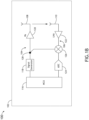
FIG. 1B illustrates a simplified block diagram of a portion of an integrated dual antenna assembly, in accordance with one or more embodiments of the disclosure; -
FIG. 1C illustrates a simplified block diagram of a portion of an integrated single antenna assembly, in accordance with one or more embodiments of the disclosure; -
FIG. 2A illustrates a simplified block diagram of an integrated dual antenna LRA; -
FIG. 2B illustrates a simplified block diagram of an integrated dual antenna LRA; -
FIG. 2C illustrates a simplified block diagram of an integrated single antenna LRA, in accordance with one or more embodiments of the disclosure; -
FIG. 2D illustrates a simplified block diagram of an integrated single antenna LRA; -
FIG. 3 illustrates a method or process for active leakage cancellation in an LRA, in accordance with one or more embodiments of the disclosure; -
FIG. 4 a graph illustrating a comparison between a non-adapted signal and a resultant adapted signal adjusted with active leakage cancellation, in accordance with one or more embodiments of the disclosure; and -
FIG. 5 illustrates a simplified block diagram of an aircraft including an LRA, in accordance with one or more embodiments of the disclosure. - Reference will now be made in detail to the subject matter disclosed, which is illustrated in the accompanying drawings.
- As used herein a letter following a reference numeral is intended to reference an embodiment of the feature or element that may be similar, but not necessarily identical, to a previously described element or feature bearing the same reference numeral (e.g., 1, 1a, 1b). Such shorthand notations are used for purposes of convenience only and should not be construed to limit the disclosure in any way unless expressly stated to the contrary.
- Further, unless expressly stated to the contrary, "or" refers to an inclusive or and not to an exclusive or. For example, a condition A or B is satisfied by anyone of the following: A is true (or present) and B is false (or not present), A is false (or not present) and B is true (or present), and both A and B are true (or present).
- In addition, use of "a" or "an" may be employed to describe elements and components of embodiments disclosed herein. This is done merely for convenience and "a" and "an" are intended to include "one," "one or more," or "at least one," and the singular also includes the plural unless it is obvious that it is meant otherwise.
- Finally, as used herein any reference to "one embodiment" or "some embodiments" means that a particular element, feature, structure, or characteristic described in connection with the embodiment is included in at least one embodiment disclosed herein. The appearances of the phrase "in some embodiments" in various places in the specification are not necessarily all referring to the same embodiment, and embodiments may include one or more of the features expressly described or inherently present herein, or any combination of sub-combination of two or more such features, along with any other features which may not necessarily be expressly described or inherently present in the instant disclosure.
-
FIGS. 1A-5 in general illustrate a low range altimeter (LRA) with active leakage cancellation. -
FIGS. 1A-1C in general illustrate portions of anantenna assembly 100, in accordance with one or more embodiments of the disclosure. - The
antenna assembly 100 may be susceptible to leakage, which results in interference. Leakage may cause two issues, including a masking of low altitude returns and a masking of high altitude returns. For example, masking low altitude returns may cause spreading due to finite bandwidth. The masking of the low altitude returns may be addressed at least in part with post processing in software, being a static leakage term. By way of another example, masking high altitude returns may be caused by transmitter phase noise. The masking of the high altitude returns may not be cancelled with software. - As illustrated in
FIG. 1A , theantenna assembly 100 may be non-integrated, including a low range unit 102 (e.g., a housing) with atransmitter 104 and areceiver 106. Thetransmitter 104 may include aTX antenna 108 and thereceiver 106 may include anRX antenna 110 outside of thelow range unit 102 that are physically separated to address the leakage through isolation. Having multiple antennas may be, in part, to meet guidelines and/or standards set forth by, but not limited to, the Federal Aviation Administration (FAA), the European Aviation Safety Agency (EASA) or any other flight certification agency or organization; the American National Standards Institute (ANSI), Aeronautical Radio, Incorporated (ARINC), or any other standards setting organization or company; the Radio Technical Commission for Aeronautics (RTCA) or any other guidelines agency or organization; or the like. - In one example, Frequency Modulated Continuous Wave (FMCW) radar altimeters may require high TX/RX isolation in order to prevent leakage paths from desensitizing the receiver due to finite transmitter phase noise and noise floor. For instance, TX/RX isolation in a Minimum Operational Performance Standards (MOPS) LRA installation may be at least 75 decibels (dB), which may be met by separating non-integrated antennas. The physical separation, however, may create siting issues for the antenna and corresponding components on an aircraft, where multiple antennas are required and/or installed. For example, a requirement of six antennas and an operation frequency of 4.3 GHz may require a number of large radio frequency (RF) feeder cables and siting locations for the antenna on the aircraft.
- As illustrated in
FIG. 1B , anantenna assembly 100 may be integrated, with theTX antenna 108 and theRX antenna 110 also housed within thelow range unit 102 in addition to thetransmitter 104 and thereceiver 106. TheTX antenna 108 and theRX antenna 110 may be physically separated to address the leakage through isolation. Because of the integrated nature of theantenna assembly 100, however, the ability to isolate may be limited due to proximity, with a minimum isolation reaching only approximately between 30 and 40 dB. - As illustrated in
FIG. 1C , theantenna assembly 100 may be integrated, including an integratedsingle antenna 112, or combination transmitting and receiving (TX/RX)antenna 112, for both thetransmitter 104 and thereceiver 106. Theantenna assembly 100 illustrated inFIG. 1C may include an RF circulator-basedduplexer 114 between thetransmitter 104 and thereceiver 106. For example, the RF circulator-basedduplexer 114 may allow for transmitting of a signal from thetransmitter 104 through the TX/RX antenna 112 and/or allow for the receiving of the signal via thereceiver 106 from the TX/RX antenna 112. The integratedsingle antenna 112 may require a different solution for the leakage, due to being unable to be physically separated. - Known integrated builds may not include antennas that are sufficiently physically separated to provide a necessary or desired level of isolation addressing the leakage, leading to issues caused by leakage being more severe in an integrated LRA due to the reduced physical separation. For example, reducing the system sensitivity through isolation of the TX/
RX antenna 112 in an integrated LRA build may be infeasible or may provide unacceptable performance degradation due to TX phase noise, even assuming an FMCW source with very low phase noise proximity, with a minimum isolation reaching only approximately 10 dB. - Despite this, the
antenna assembly 100 being integrated is still desirable to be competitive in a market. For example, the cost to manufacture and install may be greatly reduced. By way of another example, the integrated design may result in a smaller footprint allowing for installation on smaller aircraft, resulting in a safer aircraft and shared airspace. The integrating of theantenna assembly 100 with either an integrated dual antenna or an integrated single antenna would allow for all electronics related to theantenna assembly 100 to be mounted at a single location on an aircraft, including the removal of a number of radio frequency (RF) feeder cables and a number of other antenna from theantenna assembly 100, thus reducing cost, size, and need for multiple locations on the aircraft. The reduction of size and need for multiple locations on the aircraft may reduce installation issues on the aircraft (e.g., that might be present with dual or triple location installations). - As such, it would be desirable to provide a low range altimeter with active leakage cancellation. The
antenna assembly 100 should include an active leakage cancellation circuit configured to inject an appropriate cancellation signal in the front of a receiver or receiver. A microcontroller unit (MCU) of theantenna assembly 100 should be configured to determine a gain and phase, and/or an in-phase and quadrature (I and Q), for the cancellation signal. The MCU of theantenna assembly 100 should be configured to adapt the cancellation signal at various points in the frequency sweep of the signal to reduce or cancel the leakage. The MCU of theantenna assembly 100 should be configured to synchronize the gain and phase adjustments with the frequency sweep of the signal. The MCU of theantenna assembly 100 should be configured to synchronize the I and Q adjustments with the frequency sweep of the signal. As such, theantenna assembly 100 should include both a hardware component and a software component configured to mitigate the masking of low altitude returns and the masking of high altitude returns due to the leakage. -
FIGS. 2A-2D in general illustrate anintegrated LRA 200 with an activeleakage cancellation circuit 202.Fig.2C illustrates an embodiment of the present invention;Figs.2A ,2B and2D illustrate comparative examples. In particular,FIG. 2A illustrates an integrateddual antenna LRA 200. In addition,FIG. 2B illustrates an integratedsingle antenna LRA 200. It is noted herein "active leakage cancellation circuit" and variants including, but not limited to, "active cancellation circuit," "cancellation circuit," or the like may be considered equivalent, for purposes of the disclosure. - In
FIGS. 2A-2D , theintegrated LRA 200 may include anMCU 116. TheMCU 116 may be coupled to thetransmitter 104 and configured to transmit information via thetransmitter 104. TheMCU 116 may be coupled to thereceiver 106 and configured to receive information via thereceiver 106. - The
transmitter 104 may include asignal generator 118. For example, thesignal generator 118 may produce an FMCW signal. By way of another example, thesignal generator 118 may produce any spread spectrum signal. In general, theactive cancellation circuit 202 may operate with any signal types and/or architecture known in the art. - The
transmitter 104 may include a power amplifier (PA) 120. Thesignal generator 118 may be coupled to thePA 120. In one example, as illustrated inFIG. 2A , thePA 120 may be directly coupled to theTX antenna 108, such that thePA 120 supplies theTX antenna 108 with a modified or unmodified portion of the signal from thesignal generator 118. In another example, as illustrated inFIG. 2B , thePA 120 may be coupled to the RF circulator-basedduplexer 114, which may in turn be coupled to the TX/RX antenna 112, such that the RF circulator-basedduplexer 114 supplies theTX antenna 108 with a modified or unmodified portion of the signal from thesignal generator 118. - The
receiver 106 may include a low-noise amplifier (LNA) 122. In one example, as illustrated inFIG. 2A , theRX antenna 110 may be directly coupled to theLNA 122. In another example, as illustrated inFIG. 2B , the TX/RX antenna 112 may be coupled to the RF circulator-basedduplexer 114, which may in turn be coupled to theLNA 122. - The
receiver 106 may include an intermediate frequency (IF) analog-to-digital converter (ADC) 124. TheLNA 122 may be coupled to theADC 124, such that theLNA 122 supplies theADC 124 with a modified or unmodified portion of the signal from theRX antenna 108. - The
receiver 106 and/or thetransmitter 104 may include afrequency mixer 126. It is noted herein thefrequency mixer 126 may be positioned at any location within the circuit(s) forming thereceiver 106 and/or thetransmitter 104. - The
active cancellation circuit 202 may include a digital-to-analog converter (DAC) 204. For example, a first channel of theDAC 204 may be coupled to theMCU 116 and to avariable attenuator 206, and a second channel of theDAC 204 may be coupled to theMCU 116 and to aphase shifter 208. For instance, thevariable attenuator 206 and thephase shifter 208 may be in series within theactive cancellation circuit 202. By way of another example, the first and second channels of theDAC 204 may be coupled to theMCU 116 and the in-phase and quadrature (I and Q) inputs of avector modulator 210, respectively. For example, thevector modulator 210 may include a quadrature modulator or other orthogonal modulator. It is noted herein theactive cancellation circuit 202 may include either or both of thevariable attenuator 206 and thephase shifter 208, and thevector modulator 210. - Referring now to
FIGS. 2A and2B , the integrateddual antenna LRA 200 may observe leakage between theTX antenna 108 and theRX antenna 110, instead of seeing only a (or any) reflection signal from the ground. In the integrateddual antenna LRA 200, thevariable attenuator 206 and the phase shifter 208 (e.g., as illustrated inFIG. 2A ) and/or the vector modulator 210 (e.g., as illustrated inFIG 2B ) may exit thetransmitter 104 behind thePA 120 at a node orlocation 212, and may enter thereceiver 106 in front of theLNA 122 at a node orlocation 214. In this regard, some amount of the transmitted signal may be fed directly from thetransmitter 104 and to thereceiver 106 to reduce or cancel the self-reading caused by leakage between theTX antenna 108 and theRX antenna 110. - Referring now to
FIG. 2C and2D , the integratedsingle antenna LRA 200 may have leakage passing from thetransmitter 104, through the RF circulator-basedduplexer 114, and directly into thereceiver 106 in addition to the reflection signal from the ground received via the TX/RX antenna 112. In the integratedsingle antenna LRA 200, thevariable attenuator 206 and the phase shifter 208 (e.g., as illustrated inFIG. 2C ) and/or the vector modulator 210 (e.g., as illustrated inFIG. 2D ) may exit thetransmitter 104 in front of thePA 120 at a node or location 216 and enter thereceiver 106 in front of theLNA 122 at the node orlocation 214. - Unlike the integrated
dual antenna LRA 200, which may have a minimum isolation of approximately 40 dB, the integratedsingle antenna LRA 200 may have a minimum isolation of only approximately 10 dB, as the isolating element in theintegrated LRA 200 is largely the RF circulator-basedduplexer 114. Due to this, the leakage signal may be too strong to be reduced or cancelled by just thevariable attenuator 206 and thephase shifter 208, and/or thevector modulator 210. - To increase the strength of the cancellation path through the
active cancellation circuit 202, theactive cancellation circuit 202 may include anadditional amplifier 218 after thevariable attenuator 206 and thephase shifter 208 and before the node orlocation 214. Although not shown, it is noted theadditional amplifier 218 may be added to either the integratedsingle antenna LRA 200 or the integrateddual antenna LRA 200. - It is noted herein "coupled to" may mean one or more of "communicatively coupled to," "electrically coupled to," and/or "physically coupled to," for purposes of the present disclosure.
- It is noted herein directions such as "behind" or "in front" may be understood to be relative to movement or flow of the signal within the
transmitter 104 thereceiver 106, and/or theactive cancellation circuit 202. - Although embodiments of the disclosure illustrate the
LRA 200 as including one or more integrated antennas, it is noted herein theactive cancellation circuit 202 may be used withLRA 200 including non-integrated antennas (e.g., antennas outside thelow range unit 102, as illustrated inFIG. 1A ). Therefore, the above description should not be interpreted as a limitation on the present disclosure but merely an illustration. -
FIG. 3 illustrates a method orprocess 300 for active cancellation of leakage in theintegrated LRA 200, in accordance with one or more embodiments of the disclosure.FIG. 4 is a graph illustrating a comparison between a non-adapted signal and a resultant adapted signal adjusted with active leakage cancellation, in accordance with one or more embodiments of the disclosure. - In a
step 302, a static leakage reading may be measured from a receiver of an integrated LRA. The static leakage reading may be an output of the ADC 124 (e.g., as measured by the MCU 116).Line 402 of thegraph 400, as illustrated inFIG. 4 , is an example representation of the output of theADC 124 prior to the active cancellation of the leakage. - In a
step 304, a portion of a transmit signal may be received by an active cancellation circuit. As illustrated inFIG. 2A , the portion of the transmitted signal from thetransmitter 104 may be received behind thePA 120. As illustrated inFIG. 2B , the portion of the transmitted signal from thetransmitter 104 may be received in front of thePA 120. - In a
step 306, one or more gain adjustments are determined. In astep 308, one or more phase adjustments are determined. The algorithm may receive the static leakage reading taken from theADC 124 and determine one or more settings for thevariable attenuator 206 and/or thephase shifter 208 based on the static leakage reading. In addition, or in the alternative, the algorithm may receive the static leakage reading taken from theADC 124 and determine one or more settings for the vector modulator210 based on the static leakage reading. The determination of the gain adjustments and/or the phase adjustments may be performed via theMCU 116. - In a
step 310, the one or more gain adjustments are performed on the portion of the transmitted signal via a variable attenuator. In astep 312, the one or more phase adjustments are performed on the portion of the signal via a phase shifter. TheMCU 116 may adjust an output of theactive cancellation circuit 202 via thevariable attenuator 206 and/or thephase shifter 208. In addition, or in the alternative, theMCU 116 may adjust an output of theactive cancellation circuit 202 via thevector modulator 210. - In a
step 314, the adjusted portion of the transmitted signal is injected to the receiver of the integrated LRA. TheMCU 116 may again measure the static leakage reading may be an output of theADC 124 after the active cancellation of the leakage to confirm the cancellation and continue to monitor thereceiver 106.Line 404 of thegraph 400, as illustrated inFIG. 4 , is an example representation of the output of theADC 124 after the active cancellation of the leakage. - In this regard, the active cancellation of the leakage may occur during operation of the aircraft (e.g., on-the-fly). Although embodiments of the disclosure illustrate the use of the algorithm configured to constantly adjust the output of the
active cancellation circuit 202 during operation of the aircraft, however, it is noted herein a look-up table may be employed at one or more stages of flight to assist in the leakage cancellation (e.g., as a starting point or calibration tool, or the like). However, a lookup table may require compensation for temperature to be determined, while the algorithm may not need the temperature compensation to adjust the reducing or cancelling the leakage signal. Therefore, the above description should not be interpreted as a limitation on the present disclosure but merely an illustration. - It is noted herein the method or
process 300 is not limited to the steps and/or sub-steps provided. The method orprocess 300 may include more or fewer steps and/or sub-steps. In addition, the method orprocess 300 may perform the steps and/or sub-steps simultaneously. Further, the method orprocess 300 may perform the steps and/or sub-steps sequentially, including in the order provided or an order other than provided. Therefore, the above description should not be interpreted as a limitation on the scope of the disclosure but merely an illustration. -
FIG. 5 illustrates anaircraft 500 including the integratedLRA 200, in accordance with one or more embodiments of the disclosure. - Where the
MCU 116 is installed within theintegrated LRA 200, theMCU 116 may be coupled to a separateprimary controller 502 installed within theaircraft 500. - Although embodiments of the disclosure illustrate the
MCU 116 as being a component within theintegrated LRA 200, however, it is noted herein the functions and operations performed by theMCU 116 may be performed by theprimary controller 502 within theaircraft 500. In this regard, theMCU 116 may not be necessary within theintegrated LRA 200, and any embodiment directed to operations or functions by theMCU 116 may be also directed to theprimary controller 502. - The
primary controller 502 may include one ormore processors 504 configured to execute program instructions maintained onmemory medium 506. TheMCU 116 may include one ormore processors 508 configured to execute program instructions maintained onmemory medium 510. In this regard, the one ormore processors primary controller 502 or theMCU 116, respectively, may execute any of the various process steps described throughout the present disclosure. - The one or
more processors primary controller 502 or theMCU 116, respectively may include any processor or processing element known in the art. For the purposes of the present disclosure, the term "processor" or "processing element" may be broadly defined to encompass any device having one or more processing or logic elements (e.g., one or more micro-processor devices, one or more application specific integrated circuit (ASIC) devices, one or more field programmable gate arrays (FPGAs), or one or more digital signal processors (DSPs)). In this sense, the one ormore processors more processors integrated LRA 200, as described throughout the present disclosure. - Moreover, different subsystems of the
aircraft 500, such as theintegrated LRA 200 itself including theMCU 116 or other components of theintegrated LRA 200, may include a processor or logic elements suitable for carrying out at least a portion of the steps described in the present disclosure. Therefore, the above description should not be interpreted as a limitation on the embodiments of the present disclosure but merely as an illustration. Further, the steps described throughout the present disclosure may be carried out by a singleprimary controller 502 or theMCU 116, respectively or, alternatively, multiple controllers. In addition, theprimary controller 502 or theMCU 116, respectively may include one or more controllers housed in a common housing or within multiple housings. In this way, any controller or combination of controllers may be separately packaged as a module suitable for integration into the defect detection system. Further, theprimary controller 502 or theMCU 116, respectively may analyze a signal received from the detector and feed the signal to additional components within theintegrated LRA 200 or external to theintegrated LRA 200. - The
memory medium more processors memory medium memory medium memory medium more processors memory medium more processors primary controller 502 or theMCU 116, respectively. For instance, the one ormore processors primary controller 502 or theMCU 116, respectively may access a remote memory (e.g., server), accessible through a network (e.g., internet, intranet and the like). - In one embodiment, a user interface is communicatively coupled to the
primary controller 502 or theMCU 116, respectively. In one embodiment, the user interface may include, but is not limited to, one or more desktops, laptops, tablets, and the like. In another embodiment, the user interface includes a display used to display data of thesystem 500 to a user. The display of the user interface may include any display known in the art. For example, the display may include, but is not limited to, a liquid crystal display (LCD), an organic light-emitting diode (OLED) based display, or a CRT display. Those skilled in the art should recognize that any display device capable of integration with a user interface is suitable for implementation in the present disclosure. In another embodiment, a user may input selections and/or instructions responsive to data displayed to the user via a user input device of the user interface. - Although embodiments of the disclosure are directed to the
variable attenuator 206 and thephase shifter 208, and/or thevector modulator 210, being coupled to theMCU 116 and controlled by theMCU 116 to make gain and phase adjustments within theactive cancellation circuit 202, it is noted herein thevariable attenuator 206 and thephase shifter 208, and/or thevector modulator 210, may be manually adjustable by a user via a user input device (e.g., a toggle, switch, knob, or other user input device). For example, the user interface may display an adjustment to gain or phase determined based on the static leakage reading from theADC 124, and the user may interact with the user input device to make the appropriate adjustments within theactive cancellation circuit 202. - In another embodiment, the
primary controller 502 or theMCU 116, respectively is communicatively coupled to one or more elements of theintegrated LRA 200. In this regard, theprimary controller 502 or theMCU 116, respectively may transmit and/or receive data from any component of theintegrated LRA 200. Further, theprimary controller 502 or theMCU 116, respectively may direct or otherwise control any component of theintegrated LRA 200. - For example, the
primary controller 502 or theMCU 116, respectively may be programmed to execute an algorithm configured to constantly take a static leakage reading from theADC 124, determine gain adjustments and/or phase adjustments to reduce or cancel leakage observed in the static leakage reading, and adjust an output of theactive cancellation circuit 202 via thevariable attenuator 206 and/or thephase shifter 208, and/or via thevector modulator 210, based on the determined gain adjustments and/or phase adjustments during operation of the aircraft. - In this regard, the
integrated LRA 200 includes the activeleakage cancellation circuit 202 configured to inject an appropriate cancellation signal in the front of a receiver orreceiver 106. TheMCU 116 of theintegrated LRA 200 is configured to determine a gain and phase for the cancellation signal. The MCU of theintegrated LRA 200 is configured to adapt the cancellation signal at various points in the frequency sweep of the signal to reduce or cancel the leakage. The MCU of theintegrated LRA 200 is configured to synchronize the gain and phase adjustments with the frequency sweep of the signal. As such, theintegrated LRA 200 includes both a hardware component and a software component configured to mitigate the masking of low altitude returns and the masking of high altitude returns in the leakage. - Although embodiments of the disclosure illustrate the
integrated LRA 200 being coupled to theaircraft 500, it is noted herein, however, that theintegrated LRA 200 and/or components of theintegrated LRA 200 are not limited to the aviation environment and/or the aircraft components within the aviation environment. For example, theintegrated LRA 200 and/or components of theintegrated LRA 200 may be configured for any type of vehicle known in the art. For instance, the vehicle may be any air, space, land, or water-based personal equipment or vehicle; any air, space, land, or water-based commercial equipment or vehicle; any air, space, land, or water-based military equipment or vehicle known in the art. By way of another example, theintegrated LRA 200 and/or components of theintegrated LRA 200 may be configured for commercial or industrial use in either a home or a business. Therefore, the above description should not be interpreted as a limitation on the present disclosure but merely an illustration.
Claims (8)
- A low range altimeter, LRA, comprising:a transmitter (104) including a signal generator (118), a first node (216), and a power amplifier (120), the signal generator configured to produce a frequency modulated continuous wave signal, the first node coupled between the signal generator and the power amplifier;a receiver (106) including a low-noise amplifier (122), a mixer (126), and an analog-to-digital converter (124), the mixer coupled between the low-noise amplifier, the first node, and the analog-to-digital converter;at least one antenna (112), the transmitter (104) configured to transmit a first signal via the at least one antenna, the receiver (106) configured to receive a second signal via the at least one antenna, the first signal being a transmitted signal and the second signal being a received signal;an active leakage cancellation circuit (202) including a digital-to-analog converter (204), a variable attenuator (206), a phase shifter (208), and an additional amplifier (218), the transmitter exiting to the variable attenuator of the active leakage cancellation circuit in front of the power amplifier by which the active leakage cancellation circuit is configured to receive a portion of the transmitted signal from the transmitter, the active leakage cancellation circuit configured to adjust a gain and a phase of the portion of the transmitted signal to generate a cancellation signal by the variable attenuator, the phase shifter, and the additional amplifier, the additional amplifier provided after the variable attenuator and the phase shifter, the active leakage cancellation circuit entering the receiver in front of the low noise amplifier by which the active leakage cancellation circuit is configured to inject the cancellation signal into the receiver to reduce leakage observed in the received signal; anda microcontroller unit (116), MCU, the MCU configured to:measure a static leakage reading from the analog-to-digital converter;determine one or more gain adjustments for the variable attenuator and one or more phase adjustments for the phase shifter based on the static leakage reading; andcause the variable attenuator to adjust the gain and cause the phase shifter to adjust the phase for generating the cancellation signal.
- The LRA of Claim 1, the at least one antenna including a transmitting, TX, antenna (108) coupled to the transmitter, the at least one antenna including a receiving, RX, antenna (110) coupled to the receiver, the leakage observed from the transmitting antenna by the receiving antenna.
- The LRA of Claim 1, the at least one antenna including a combination transmitting and receiving, TX/RX, antenna (112) coupled to the transmitter and the receiver.
- The LRA of Claim 3, further comprising:
a radio frequency, RF, circulator-based duplexer (114) positioned between the transmitter, the receiver, and the combination TX/RX antenna (108, 110, 112), the leakage observed through the RF circulator-based duplexer in addition to the received signal. - The LRA of Claim 1, the adjustment to gain and phase being synchronized with a frequency sweep of the signal.
- The LRA of Claim 1, the active leakage cancellation circuit comprising:
a vector modulator (210) configured to adjust the in-phase and quadrature (I and Q) of the transmitted signal. - The LRA of Claim 6, the adjustment to I and Q being controlled by the MCU in response to the MCU determining the I and Q based on the static leakage reading.
- The LRA of Claim 6, the adjustment to I and Q being synchronized with a frequency sweep of the signal.
Applications Claiming Priority (1)
| Application Number | Priority Date | Filing Date | Title |
|---|---|---|---|
| US17/039,150 US11592550B2 (en) | 2020-09-30 | 2020-09-30 | Low range altimeter active leakage cancellation |
Publications (2)
| Publication Number | Publication Date |
|---|---|
| EP3978871A1 EP3978871A1 (en) | 2022-04-06 |
| EP3978871B1 true EP3978871B1 (en) | 2024-06-05 |
Family
ID=78269571
Family Applications (1)
| Application Number | Title | Priority Date | Filing Date |
|---|---|---|---|
| EP21199823.2A Active EP3978871B1 (en) | 2020-09-30 | 2021-09-29 | Low range altimeter active leakage cancellation |
Country Status (2)
| Country | Link |
|---|---|
| US (1) | US11592550B2 (en) |
| EP (1) | EP3978871B1 (en) |
Families Citing this family (1)
| Publication number | Priority date | Publication date | Assignee | Title |
|---|---|---|---|---|
| US12061249B1 (en) * | 2021-11-09 | 2024-08-13 | National Technology & Engineering Solutions Of Sandia, Llc | Radar transmit bandwidth augmentation |
Family Cites Families (15)
| Publication number | Priority date | Publication date | Assignee | Title |
|---|---|---|---|---|
| US3341849A (en) | 1966-01-26 | 1967-09-12 | Bendix Corp | Self-calibrating, self-testing radio altimeter |
| US4806935A (en) | 1987-09-17 | 1989-02-21 | Fosket Timothy G | Closed loop velocity/altitude sensor for FM-CW doppler radars |
| US6426717B1 (en) | 2001-05-11 | 2002-07-30 | Rockwell Collins, Inc. | Single antenna FM radio altimeter operating in a continuous wave mode and an interrupted continuous wave mode |
| US7239266B2 (en) | 2004-08-26 | 2007-07-03 | Honeywell International Inc. | Radar altimeter |
| US7161527B2 (en) | 2004-09-03 | 2007-01-09 | Honeywell International Inc. | Navigation system |
| US7576683B2 (en) | 2006-08-07 | 2009-08-18 | Honeywell International Inc. | Methods and systems for reducing interference caused by antenna leakage signals |
| US9297885B2 (en) | 2012-07-27 | 2016-03-29 | Honeywell International Inc. | Method of system compensation to reduce the effects of self interference in frequency modulated continuous wave altimeter systems |
| US9678197B2 (en) | 2013-09-26 | 2017-06-13 | Honeywell International Inc. | FMCW radar with refined measurement using fixed frequencies |
| US10018716B2 (en) | 2014-06-26 | 2018-07-10 | Honeywell International Inc. | Systems and methods for calibration and optimization of frequency modulated continuous wave radar altimeters using adjustable self-interference cancellation |
| DE102016120185B4 (en) * | 2016-10-24 | 2018-05-30 | Infineon Technologies Ag | Radar transceiver with compensation of phase noise |
| KR20180110269A (en) | 2017-03-27 | 2018-10-10 | 한국전자통신연구원 | Radar device |
| US10557934B1 (en) | 2017-06-30 | 2020-02-11 | Rockwell Collins, Inc. | Altimeter apparatus for external fuselage mounting |
| EP3707943B1 (en) * | 2017-11-06 | 2022-01-05 | Telefonaktiebolaget LM Ericsson (publ) | Method and apparatus for obstacle detection |
| EP3667358B1 (en) * | 2018-12-11 | 2024-03-06 | NXP USA, Inc. | Leakage cancellation in a radar receiver |
| EP3696563B1 (en) * | 2019-02-14 | 2023-06-07 | IMEC vzw | Transmitter-receiver leakage suppression in integrated radar systems |
-
2020
- 2020-09-30 US US17/039,150 patent/US11592550B2/en active Active
-
2021
- 2021-09-29 EP EP21199823.2A patent/EP3978871B1/en active Active
Also Published As
| Publication number | Publication date |
|---|---|
| US11592550B2 (en) | 2023-02-28 |
| EP3978871A1 (en) | 2022-04-06 |
| US20220099821A1 (en) | 2022-03-31 |
Similar Documents
| Publication | Publication Date | Title |
|---|---|---|
| US11789118B2 (en) | Calibration of a phased array | |
| US9767699B1 (en) | System for and method of detecting drones | |
| EP1901087B1 (en) | Distributed and cable reduced TCAS | |
| US7969349B2 (en) | System and method for suppressing close clutter in a radar system | |
| CN108051668B (en) | Testing method for simulating and calibrating radiation emission interference of PEDs in airplane cabin | |
| US20140111372A1 (en) | Sensor system and method for determining target location using sparsity-based processing | |
| US20090109085A1 (en) | Method and system for calibrating an antenna array for an aircraft surveillance system | |
| EP3978871B1 (en) | Low range altimeter active leakage cancellation | |
| Aldowesh et al. | A passive bistatic radar experiment for very low radar cross-section target detection | |
| US6748351B1 (en) | Modular covert remote electronic warfare simulator | |
| Futatsumori et al. | Interference path loss measurements of beechcraft B300 aircraft at 4 GHz wireless avionics intra-communication band | |
| US10714815B2 (en) | Systems and methods for providing a DME L-band shared antenna | |
| CN116299443A (en) | Geo-SAR satellite image index improvement method based on dual-band joint | |
| US20180033319A1 (en) | Systems and methods for providing an integrated tcas and dme system using an omnidirectional antenna | |
| Wang | Application of near-space passive radar for homeland security | |
| CN210927616U (en) | Interference suppression system for airborne electromagnetic wave equipment | |
| US20190018105A1 (en) | Method for Calibrating an Active Sensor System | |
| US10948585B1 (en) | Dual band radar altimeter system and method | |
| Jaromi et al. | Structure and software elements of ENAVI radar for large drones | |
| KR101953356B1 (en) | Apparatus for Processing Correction Coefficient of Array Antenna Application System | |
| Nguyen et al. | Determination of receiver susceptibility to radio frequency interference from portable electronic devices | |
| GB2318237A (en) | Pulse doppler radar device with elimination of jammer by neutralization | |
| Nguyen et al. | Small aircraft RF interference path loss | |
| US20260110797A1 (en) | Dual architecture radar | |
| Gordon | Reconfigurable RF Transmitters for C-Band and X-Band: Design, Development and Testing |
Legal Events
| Date | Code | Title | Description |
|---|---|---|---|
| PUAI | Public reference made under article 153(3) epc to a published international application that has entered the european phase |
Free format text: ORIGINAL CODE: 0009012 |
|
| STAA | Information on the status of an ep patent application or granted ep patent |
Free format text: STATUS: THE APPLICATION HAS BEEN PUBLISHED |
|
| AK | Designated contracting states |
Kind code of ref document: A1 Designated state(s): AL AT BE BG CH CY CZ DE DK EE ES FI FR GB GR HR HU IE IS IT LI LT LU LV MC MK MT NL NO PL PT RO RS SE SI SK SM TR |
|
| STAA | Information on the status of an ep patent application or granted ep patent |
Free format text: STATUS: REQUEST FOR EXAMINATION WAS MADE |
|
| 17P | Request for examination filed |
Effective date: 20221005 |
|
| RBV | Designated contracting states (corrected) |
Designated state(s): AL AT BE BG CH CY CZ DE DK EE ES FI FR GB GR HR HU IE IS IT LI LT LU LV MC MK MT NL NO PL PT RO RS SE SI SK SM TR |
|
| GRAP | Despatch of communication of intention to grant a patent |
Free format text: ORIGINAL CODE: EPIDOSNIGR1 |
|
| STAA | Information on the status of an ep patent application or granted ep patent |
Free format text: STATUS: GRANT OF PATENT IS INTENDED |
|
| INTG | Intention to grant announced |
Effective date: 20240123 |
|
| GRAS | Grant fee paid |
Free format text: ORIGINAL CODE: EPIDOSNIGR3 |
|
| GRAA | (expected) grant |
Free format text: ORIGINAL CODE: 0009210 |
|
| STAA | Information on the status of an ep patent application or granted ep patent |
Free format text: STATUS: THE PATENT HAS BEEN GRANTED |
|
| AK | Designated contracting states |
Kind code of ref document: B1 Designated state(s): AL AT BE BG CH CY CZ DE DK EE ES FI FR GB GR HR HU IE IS IT LI LT LU LV MC MK MT NL NO PL PT RO RS SE SI SK SM TR |
|
| REG | Reference to a national code |
Ref country code: CH Ref legal event code: EP |
|
| REG | Reference to a national code |
Ref country code: DE Ref legal event code: R096 Ref document number: 602021014033 Country of ref document: DE |
|
| REG | Reference to a national code |
Ref country code: IE Ref legal event code: FG4D |
|
| REG | Reference to a national code |
Ref country code: LT Ref legal event code: MG9D |
|
| PG25 | Lapsed in a contracting state [announced via postgrant information from national office to epo] |
Ref country code: BG Free format text: LAPSE BECAUSE OF FAILURE TO SUBMIT A TRANSLATION OF THE DESCRIPTION OR TO PAY THE FEE WITHIN THE PRESCRIBED TIME-LIMIT Effective date: 20240605 |
|
| REG | Reference to a national code |
Ref country code: NL Ref legal event code: MP Effective date: 20240605 |
|
| PG25 | Lapsed in a contracting state [announced via postgrant information from national office to epo] |
Ref country code: FI Free format text: LAPSE BECAUSE OF FAILURE TO SUBMIT A TRANSLATION OF THE DESCRIPTION OR TO PAY THE FEE WITHIN THE PRESCRIBED TIME-LIMIT Effective date: 20240605 Ref country code: HR Free format text: LAPSE BECAUSE OF FAILURE TO SUBMIT A TRANSLATION OF THE DESCRIPTION OR TO PAY THE FEE WITHIN THE PRESCRIBED TIME-LIMIT Effective date: 20240605 |
|
| PG25 | Lapsed in a contracting state [announced via postgrant information from national office to epo] |
Ref country code: GR Free format text: LAPSE BECAUSE OF FAILURE TO SUBMIT A TRANSLATION OF THE DESCRIPTION OR TO PAY THE FEE WITHIN THE PRESCRIBED TIME-LIMIT Effective date: 20240906 |
|
| PG25 | Lapsed in a contracting state [announced via postgrant information from national office to epo] |
Ref country code: ES Free format text: LAPSE BECAUSE OF FAILURE TO SUBMIT A TRANSLATION OF THE DESCRIPTION OR TO PAY THE FEE WITHIN THE PRESCRIBED TIME-LIMIT Effective date: 20240605 |
|
| PG25 | Lapsed in a contracting state [announced via postgrant information from national office to epo] |
Ref country code: LV Free format text: LAPSE BECAUSE OF FAILURE TO SUBMIT A TRANSLATION OF THE DESCRIPTION OR TO PAY THE FEE WITHIN THE PRESCRIBED TIME-LIMIT Effective date: 20240605 |
|
| PG25 | Lapsed in a contracting state [announced via postgrant information from national office to epo] |
Ref country code: NO Free format text: LAPSE BECAUSE OF FAILURE TO SUBMIT A TRANSLATION OF THE DESCRIPTION OR TO PAY THE FEE WITHIN THE PRESCRIBED TIME-LIMIT Effective date: 20240905 Ref country code: LV Free format text: LAPSE BECAUSE OF FAILURE TO SUBMIT A TRANSLATION OF THE DESCRIPTION OR TO PAY THE FEE WITHIN THE PRESCRIBED TIME-LIMIT Effective date: 20240605 Ref country code: HR Free format text: LAPSE BECAUSE OF FAILURE TO SUBMIT A TRANSLATION OF THE DESCRIPTION OR TO PAY THE FEE WITHIN THE PRESCRIBED TIME-LIMIT Effective date: 20240605 Ref country code: GR Free format text: LAPSE BECAUSE OF FAILURE TO SUBMIT A TRANSLATION OF THE DESCRIPTION OR TO PAY THE FEE WITHIN THE PRESCRIBED TIME-LIMIT Effective date: 20240906 Ref country code: FI Free format text: LAPSE BECAUSE OF FAILURE TO SUBMIT A TRANSLATION OF THE DESCRIPTION OR TO PAY THE FEE WITHIN THE PRESCRIBED TIME-LIMIT Effective date: 20240605 Ref country code: ES Free format text: LAPSE BECAUSE OF FAILURE TO SUBMIT A TRANSLATION OF THE DESCRIPTION OR TO PAY THE FEE WITHIN THE PRESCRIBED TIME-LIMIT Effective date: 20240605 Ref country code: BG Free format text: LAPSE BECAUSE OF FAILURE TO SUBMIT A TRANSLATION OF THE DESCRIPTION OR TO PAY THE FEE WITHIN THE PRESCRIBED TIME-LIMIT Effective date: 20240605 Ref country code: RS Free format text: LAPSE BECAUSE OF FAILURE TO SUBMIT A TRANSLATION OF THE DESCRIPTION OR TO PAY THE FEE WITHIN THE PRESCRIBED TIME-LIMIT Effective date: 20240905 |
|
| PG25 | Lapsed in a contracting state [announced via postgrant information from national office to epo] |
Ref country code: NL Free format text: LAPSE BECAUSE OF FAILURE TO SUBMIT A TRANSLATION OF THE DESCRIPTION OR TO PAY THE FEE WITHIN THE PRESCRIBED TIME-LIMIT Effective date: 20240605 |
|
| REG | Reference to a national code |
Ref country code: AT Ref legal event code: MK05 Ref document number: 1692749 Country of ref document: AT Kind code of ref document: T Effective date: 20240605 |
|
| PG25 | Lapsed in a contracting state [announced via postgrant information from national office to epo] |
Ref country code: NL Free format text: LAPSE BECAUSE OF FAILURE TO SUBMIT A TRANSLATION OF THE DESCRIPTION OR TO PAY THE FEE WITHIN THE PRESCRIBED TIME-LIMIT Effective date: 20240605 |
|
| PG25 | Lapsed in a contracting state [announced via postgrant information from national office to epo] |
Ref country code: PT Free format text: LAPSE BECAUSE OF FAILURE TO SUBMIT A TRANSLATION OF THE DESCRIPTION OR TO PAY THE FEE WITHIN THE PRESCRIBED TIME-LIMIT Effective date: 20241007 |
|
| PG25 | Lapsed in a contracting state [announced via postgrant information from national office to epo] |
Ref country code: PT Free format text: LAPSE BECAUSE OF FAILURE TO SUBMIT A TRANSLATION OF THE DESCRIPTION OR TO PAY THE FEE WITHIN THE PRESCRIBED TIME-LIMIT Effective date: 20241007 |
|
| PG25 | Lapsed in a contracting state [announced via postgrant information from national office to epo] |
Ref country code: PL Free format text: LAPSE BECAUSE OF FAILURE TO SUBMIT A TRANSLATION OF THE DESCRIPTION OR TO PAY THE FEE WITHIN THE PRESCRIBED TIME-LIMIT Effective date: 20240605 |
|
| PG25 | Lapsed in a contracting state [announced via postgrant information from national office to epo] |
Ref country code: EE Free format text: LAPSE BECAUSE OF FAILURE TO SUBMIT A TRANSLATION OF THE DESCRIPTION OR TO PAY THE FEE WITHIN THE PRESCRIBED TIME-LIMIT Effective date: 20240605 |
|
| PG25 | Lapsed in a contracting state [announced via postgrant information from national office to epo] |
Ref country code: AT Free format text: LAPSE BECAUSE OF FAILURE TO SUBMIT A TRANSLATION OF THE DESCRIPTION OR TO PAY THE FEE WITHIN THE PRESCRIBED TIME-LIMIT Effective date: 20240605 Ref country code: IS Free format text: LAPSE BECAUSE OF FAILURE TO SUBMIT A TRANSLATION OF THE DESCRIPTION OR TO PAY THE FEE WITHIN THE PRESCRIBED TIME-LIMIT Effective date: 20241005 |
|
| PG25 | Lapsed in a contracting state [announced via postgrant information from national office to epo] |
Ref country code: CZ Free format text: LAPSE BECAUSE OF FAILURE TO SUBMIT A TRANSLATION OF THE DESCRIPTION OR TO PAY THE FEE WITHIN THE PRESCRIBED TIME-LIMIT Effective date: 20240605 |
|
| PG25 | Lapsed in a contracting state [announced via postgrant information from national office to epo] |
Ref country code: RO Free format text: LAPSE BECAUSE OF FAILURE TO SUBMIT A TRANSLATION OF THE DESCRIPTION OR TO PAY THE FEE WITHIN THE PRESCRIBED TIME-LIMIT Effective date: 20240605 Ref country code: SK Free format text: LAPSE BECAUSE OF FAILURE TO SUBMIT A TRANSLATION OF THE DESCRIPTION OR TO PAY THE FEE WITHIN THE PRESCRIBED TIME-LIMIT Effective date: 20240605 |
|
| PG25 | Lapsed in a contracting state [announced via postgrant information from national office to epo] |
Ref country code: SM Free format text: LAPSE BECAUSE OF FAILURE TO SUBMIT A TRANSLATION OF THE DESCRIPTION OR TO PAY THE FEE WITHIN THE PRESCRIBED TIME-LIMIT Effective date: 20240605 |
|
| PG25 | Lapsed in a contracting state [announced via postgrant information from national office to epo] |
Ref country code: SM Free format text: LAPSE BECAUSE OF FAILURE TO SUBMIT A TRANSLATION OF THE DESCRIPTION OR TO PAY THE FEE WITHIN THE PRESCRIBED TIME-LIMIT Effective date: 20240605 Ref country code: SK Free format text: LAPSE BECAUSE OF FAILURE TO SUBMIT A TRANSLATION OF THE DESCRIPTION OR TO PAY THE FEE WITHIN THE PRESCRIBED TIME-LIMIT Effective date: 20240605 Ref country code: RO Free format text: LAPSE BECAUSE OF FAILURE TO SUBMIT A TRANSLATION OF THE DESCRIPTION OR TO PAY THE FEE WITHIN THE PRESCRIBED TIME-LIMIT Effective date: 20240605 Ref country code: PL Free format text: LAPSE BECAUSE OF FAILURE TO SUBMIT A TRANSLATION OF THE DESCRIPTION OR TO PAY THE FEE WITHIN THE PRESCRIBED TIME-LIMIT Effective date: 20240605 Ref country code: IS Free format text: LAPSE BECAUSE OF FAILURE TO SUBMIT A TRANSLATION OF THE DESCRIPTION OR TO PAY THE FEE WITHIN THE PRESCRIBED TIME-LIMIT Effective date: 20241005 Ref country code: EE Free format text: LAPSE BECAUSE OF FAILURE TO SUBMIT A TRANSLATION OF THE DESCRIPTION OR TO PAY THE FEE WITHIN THE PRESCRIBED TIME-LIMIT Effective date: 20240605 Ref country code: CZ Free format text: LAPSE BECAUSE OF FAILURE TO SUBMIT A TRANSLATION OF THE DESCRIPTION OR TO PAY THE FEE WITHIN THE PRESCRIBED TIME-LIMIT Effective date: 20240605 Ref country code: AT Free format text: LAPSE BECAUSE OF FAILURE TO SUBMIT A TRANSLATION OF THE DESCRIPTION OR TO PAY THE FEE WITHIN THE PRESCRIBED TIME-LIMIT Effective date: 20240605 |
|
| PG25 | Lapsed in a contracting state [announced via postgrant information from national office to epo] |
Ref country code: IT Free format text: LAPSE BECAUSE OF FAILURE TO SUBMIT A TRANSLATION OF THE DESCRIPTION OR TO PAY THE FEE WITHIN THE PRESCRIBED TIME-LIMIT Effective date: 20240605 |
|
| REG | Reference to a national code |
Ref country code: DE Ref legal event code: R097 Ref document number: 602021014033 Country of ref document: DE |
|
| PLBE | No opposition filed within time limit |
Free format text: ORIGINAL CODE: 0009261 |
|
| STAA | Information on the status of an ep patent application or granted ep patent |
Free format text: STATUS: NO OPPOSITION FILED WITHIN TIME LIMIT |
|
| PG25 | Lapsed in a contracting state [announced via postgrant information from national office to epo] |
Ref country code: DK Free format text: LAPSE BECAUSE OF FAILURE TO SUBMIT A TRANSLATION OF THE DESCRIPTION OR TO PAY THE FEE WITHIN THE PRESCRIBED TIME-LIMIT Effective date: 20240605 |
|
| PG25 | Lapsed in a contracting state [announced via postgrant information from national office to epo] |
Ref country code: MC Free format text: LAPSE BECAUSE OF FAILURE TO SUBMIT A TRANSLATION OF THE DESCRIPTION OR TO PAY THE FEE WITHIN THE PRESCRIBED TIME-LIMIT Effective date: 20240605 |
|
| REG | Reference to a national code |
Ref country code: CH Ref legal event code: PL |
|
| 26N | No opposition filed |
Effective date: 20250306 |
|
| PG25 | Lapsed in a contracting state [announced via postgrant information from national office to epo] |
Ref country code: LU Free format text: LAPSE BECAUSE OF NON-PAYMENT OF DUE FEES Effective date: 20240929 |
|
| REG | Reference to a national code |
Ref country code: BE Ref legal event code: MM Effective date: 20240930 |
|
| PG25 | Lapsed in a contracting state [announced via postgrant information from national office to epo] |
Ref country code: BE Free format text: LAPSE BECAUSE OF NON-PAYMENT OF DUE FEES Effective date: 20240930 |
|
| PG25 | Lapsed in a contracting state [announced via postgrant information from national office to epo] |
Ref country code: CH Free format text: LAPSE BECAUSE OF NON-PAYMENT OF DUE FEES Effective date: 20240930 |
|
| PG25 | Lapsed in a contracting state [announced via postgrant information from national office to epo] |
Ref country code: IE Free format text: LAPSE BECAUSE OF NON-PAYMENT OF DUE FEES Effective date: 20240929 |
|
| PG25 | Lapsed in a contracting state [announced via postgrant information from national office to epo] |
Ref country code: SE Free format text: LAPSE BECAUSE OF FAILURE TO SUBMIT A TRANSLATION OF THE DESCRIPTION OR TO PAY THE FEE WITHIN THE PRESCRIBED TIME-LIMIT Effective date: 20240605 |
|
| PGFP | Annual fee paid to national office [announced via postgrant information from national office to epo] |
Ref country code: DE Payment date: 20250820 Year of fee payment: 5 |
|
| PGFP | Annual fee paid to national office [announced via postgrant information from national office to epo] |
Ref country code: GB Payment date: 20250827 Year of fee payment: 5 |
|
| PGFP | Annual fee paid to national office [announced via postgrant information from national office to epo] |
Ref country code: FR Payment date: 20250820 Year of fee payment: 5 |
|
| PG25 | Lapsed in a contracting state [announced via postgrant information from national office to epo] |
Ref country code: CY Free format text: LAPSE BECAUSE OF FAILURE TO SUBMIT A TRANSLATION OF THE DESCRIPTION OR TO PAY THE FEE WITHIN THE PRESCRIBED TIME-LIMIT; INVALID AB INITIO Effective date: 20210929 |
|
| PG25 | Lapsed in a contracting state [announced via postgrant information from national office to epo] |
Ref country code: HU Free format text: LAPSE BECAUSE OF FAILURE TO SUBMIT A TRANSLATION OF THE DESCRIPTION OR TO PAY THE FEE WITHIN THE PRESCRIBED TIME-LIMIT; INVALID AB INITIO Effective date: 20210929 |