EP3978850A1 - A humidity adjusting system for a household appliance - Google Patents
A humidity adjusting system for a household appliance Download PDFInfo
- Publication number
- EP3978850A1 EP3978850A1 EP21195527.3A EP21195527A EP3978850A1 EP 3978850 A1 EP3978850 A1 EP 3978850A1 EP 21195527 A EP21195527 A EP 21195527A EP 3978850 A1 EP3978850 A1 EP 3978850A1
- Authority
- EP
- European Patent Office
- Prior art keywords
- adjusting system
- humidity adjusting
- actuator
- pin
- guide channel
- Prior art date
- Legal status (The legal status is an assumption and is not a legal conclusion. Google has not performed a legal analysis and makes no representation as to the accuracy of the status listed.)
- Withdrawn
Links
- 238000001816 cooling Methods 0.000 claims abstract description 17
- 230000008878 coupling Effects 0.000 claims description 6
- 238000010168 coupling process Methods 0.000 claims description 6
- 238000005859 coupling reaction Methods 0.000 claims description 6
- 238000004891 communication Methods 0.000 claims description 4
- 230000001105 regulatory effect Effects 0.000 claims description 2
- 235000013305 food Nutrition 0.000 description 8
- 230000007246 mechanism Effects 0.000 description 3
- 238000000034 method Methods 0.000 description 3
- 238000005452 bending Methods 0.000 description 2
- 230000007423 decrease Effects 0.000 description 2
- 238000006073 displacement reaction Methods 0.000 description 1
- 230000002349 favourable effect Effects 0.000 description 1
- 238000009920 food preservation Methods 0.000 description 1
- 238000004519 manufacturing process Methods 0.000 description 1
- 238000007665 sagging Methods 0.000 description 1
- 239000007787 solid Substances 0.000 description 1
- 230000001960 triggered effect Effects 0.000 description 1
- 235000013311 vegetables Nutrition 0.000 description 1
- XLYOFNOQVPJJNP-UHFFFAOYSA-N water Chemical compound O XLYOFNOQVPJJNP-UHFFFAOYSA-N 0.000 description 1
Images







Classifications
-
- F—MECHANICAL ENGINEERING; LIGHTING; HEATING; WEAPONS; BLASTING
- F25—REFRIGERATION OR COOLING; COMBINED HEATING AND REFRIGERATION SYSTEMS; HEAT PUMP SYSTEMS; MANUFACTURE OR STORAGE OF ICE; LIQUEFACTION SOLIDIFICATION OF GASES
- F25D—REFRIGERATORS; COLD ROOMS; ICE-BOXES; COOLING OR FREEZING APPARATUS NOT OTHERWISE PROVIDED FOR
- F25D25/00—Charging, supporting, and discharging the articles to be cooled
- F25D25/02—Charging, supporting, and discharging the articles to be cooled by shelves
- F25D25/024—Slidable shelves
- F25D25/025—Drawers
-
- F—MECHANICAL ENGINEERING; LIGHTING; HEATING; WEAPONS; BLASTING
- F25—REFRIGERATION OR COOLING; COMBINED HEATING AND REFRIGERATION SYSTEMS; HEAT PUMP SYSTEMS; MANUFACTURE OR STORAGE OF ICE; LIQUEFACTION SOLIDIFICATION OF GASES
- F25D—REFRIGERATORS; COLD ROOMS; ICE-BOXES; COOLING OR FREEZING APPARATUS NOT OTHERWISE PROVIDED FOR
- F25D17/00—Arrangements for circulating cooling fluids; Arrangements for circulating gas, e.g. air, within refrigerated spaces
- F25D17/04—Arrangements for circulating cooling fluids; Arrangements for circulating gas, e.g. air, within refrigerated spaces for circulating air, e.g. by convection
- F25D17/042—Air treating means within refrigerated spaces
-
- F—MECHANICAL ENGINEERING; LIGHTING; HEATING; WEAPONS; BLASTING
- F25—REFRIGERATION OR COOLING; COMBINED HEATING AND REFRIGERATION SYSTEMS; HEAT PUMP SYSTEMS; MANUFACTURE OR STORAGE OF ICE; LIQUEFACTION SOLIDIFICATION OF GASES
- F25D—REFRIGERATORS; COLD ROOMS; ICE-BOXES; COOLING OR FREEZING APPARATUS NOT OTHERWISE PROVIDED FOR
- F25D2317/00—Details or arrangements for circulating cooling fluids; Details or arrangements for circulating gas, e.g. air, within refrigerated spaces, not provided for in other groups of this subclass
- F25D2317/04—Treating air flowing to refrigeration compartments
- F25D2317/041—Treating air flowing to refrigeration compartments by purification
- F25D2317/0413—Treating air flowing to refrigeration compartments by purification by humidification
Definitions
- the present invention relates to a humidity adjusting system according to preamble of claim 1.
- cooling method is a widely used process for preserving freshness, directly in the domestic refrigerator appliances with which all kitchens are equipped.
- the amount of humidity in the reservoir medium is an essential parameter in conserving the freshness. Attention to the amount of humidity the food is exposed to can facilitate users to maintain freshness for the longest possible time.
- the diverse amount of humidity is required to retain items fresh for longer; that is to say, some require more humidity than others, and some are more sensitive to humidity.
- WO 2019/034371 A1 discloses a refrigerator comprising a cooler compartment, a crisper placed at the lower side of the cooler compartment, a crisper cover placed over the crisper and a humidity control mechanism mounted at the front of the crisper cover, having a rotary button enabling varying the amount of the humid air transmitted from the crisper to the internal environment of the cooler compartment.
- An object of the invention is to provide a humidity adjusting system configured to be used in a household appliance that allows users to adjust humidity level in more than one level so as to prolong the edible life of food.
- the present invention proposes a humidity adjusting system configured to be positioned in a cabinet of a household appliance, comprising an insulating cover for covering a storage container cavity so as to limit air passage from the thermally insulating case to the storage container; a frame positioned above the storage container wherein the frame has a central portion including a housing through which an actuator at least partly extends. Additionally, said humidity adjusting system further includes a connection plate which is disposed on the central portion wherein said connection plate has a fixing portion coupled to a receiving flange formed on the insulating cover for transmitting the actuator movement thereto; and guide channel which is arranged in the frame.
- the present invention allows the user more than one, particularly, three different humidity levels in a storage container to prolong the food expire date, thereby providing flexibility usage to the user in a cost-effective way.
- the guide channel comprises an initial portion in which a pin is placed, a first routing portion, a first holding portion, a first restricting portion, a second routing portion, a second holding portion and a second restricting portion. That is, a first restricting portion and a second restricting portion are individually configured to limit the backward movement of the pin in the guide channel by the help of the inclined portion. Additionally, a first holding portion and a second holding portion are individually configured to at least partly accommodate the pin. Said guide channel arrangement provides easy of manufacture and unique durable operation modes.
- the actuator is configured to move in a direction parallel to the horizontal plane of the cooling device.
- solid and durable assembly of the actuator is provided. Just as the actuator does not require a rotary motion to operate makes it easier and simpler for the user to adjust the humidity, transmitting the force applied is performed in a simple manner.
- the insulating cover further comprises at least one engagement element detachably attached to an inner liner of thermally insulating case.
- a cover housing is configured as a recess provided in the inner liner which is inclined with respect to the axis force applied on the actuator.
- the insulating cover has a first position which obstructs an aperture between the insulating cover and the storage container, a second position which partially opens the aperture and a third position in which the insulating cover remains at least partially in contact with the storage compartment.
- insulating cover is able to move in more than one axis and be located in more than one position which provides a wider gap or cavity or aperture between the insulating cover and the frame; moreover, the cavity therebetween plays an essential role as an air passage to conserve the freshness.
- the actuator further comprises at least one latching housing configured to match at least one connection protrusion which is arranged in the connection plate.
- an actuation lever is formed to protrude from actuator.
- the pin includes a contact cap associated with the actuator and a longitudinal bracing configured to extend therefrom in a direction to perpendicular to the guide channel.
- a contact cap associated with the actuator
- a longitudinal bracing configured to extend therefrom in a direction to perpendicular to the guide channel.
- the central portion has an abutment unit which is in communication with a loaded resilient member.
- the resilient member is abutted against at least one seat, more notably, two seats so as to restrict an axial forward movement.
- the position of the resilient member is accurately defined and possible waggling issue is eliminated.
- the frame further comprises at least one coupling projection which fits on a lateral surface of the connection plate for fixing the connection plate thereto.
- This fixing process minimizes operational problems such as vibration and sagging that may occur during the operation of the actuator, that is to say, fixing the frame to the connection plate via coupling projection thereof constitute a stable arrangement.
- the humidity adjusting system further comprises a display unit which matches an indicator hook arranged on the connection, thereby illustrating the degree of humidity corresponding to the position of the actuator.
- the storage container is sized and shaped as a drawer, in particular a crisper drawer.
- a drawer By having the insulating cover closed, water vapor is held in the drawer or in the crisper and the moisture retains therein.
- at least one crisper or a drawer also present the opportunity to separate foods.
- Drawers are storage areas such as that present a more humid environment than the rest of the interior which is intended for accommodating foods and is bounded by walls.
- a cooling device comprising said humidity adjusting system
- the cooling device can be a refrigerator, a freezer or a fridge-freezer combination device.
- the present invention relates to a humidity adjusting system (100) for a storage container (85) located within a thermally insulating case (80) of a cooling device (90).
- said humidity adjusting system(100) comprises an insulating cover (40) for covering the storage container (85) cavity so as to limit air passage from the thermally insulating case (80) to the storage container (85); a frame (10) positioned above the storage container (85) wherein the frame (10) has a central portion (16) including a housing (17) through which an actuator (30) at least partly extends as illustrated in Fig. 2 , a connection plate (20) which is disposed on the central portion (16) as illustrated in Fig. 9 .
- connection plate (20) has a fixing portion (21) coupled to a receiving flange (43) formed on the insulating cover (40) for transmitting the actuator (30) movement thereto and a connection groove (23) which is in communication with a corresponding protrusion arranged in the actuator (30) as depicted in Fig. 4 and Fig. 5 .
- Said frame (10) further comprises a guide channel (11) which is arranged therein. Moreover the guide channel (11) is a monolithic with the frame (10) and has substantially predetermined width and a degree of curvature.
- the guide channel (11) has more than one edges, some of which have a curved shapes, particularly, convex and/or concave shapes.
- the guide channel (11) has more than one bending portions, wherein said bending portions has at least one convex shape and/or at least one concave shape.
- the guide channel (11) has both concave inner edges and convex inner edges, wherein said edges are configured and dimensioned to at least partially guide a pin (70).
- the guide channel (11) comprises an initial portion (112) in which the pin (70) is placed, a first routing portion (113), a first holding portion (114), a first restricting portion (115), a second routing portion (116), a second holding portion (117) and a second restricting portion (118). That is, the first restricting portion (115) and the second restricting portion (118) are individually configured to limit the backward movement of the pin (70) in the guide channel (11) by the help of the inclined portion. Additionally, the first holding portion (114) and the second holding portion (117) are individually configured to at least partly accommodate the pin (70).
- first restricting portion (115) and the second restricting portion (118) are of substantially concave shape.
- first routing portion (113) and the second routing portion (116) are of substantially convex shape.
- the guide channel (11) further includes a first tubular portion (119) and a second tubular portion (120).
- An end which is proximal to the initial portion (112) of the first tubular portion (119) is closer to the initial portion (112) with respect to an end proximal to the initial portion (112) of the second tubular portion (120).
- the end of the second tubular portion (120) is located at a distance and height that the pin (70) advancing to return to the initial portion (112) along the first tubular portion (119) can not enter the second tubular portion (120).
- the guide channel (11) comprises a setting portion (111) which is aligned with a pin mounting slot (25) located on the connection plate (20).
- the pin (70) is mounted to the humidity adjusting system (100) through the pin mounting slot (25) as shown in Fig. 5 .
- durable assembly of the pin (70) is provided in a cost-effective way which decreases the requirements of experienced assembly technicians.
- the frame (10) further comprises at least one coupling projection (13) which fits on a lateral surface (24) of the connection plate (20) for fixing the connection plate (20) thereto.
- This fixing process decreases the operational issues, that is to say, fixing the frame (10) to the connection plate (20) via the coupling projection (13) constitutes a stable arrangement.
- a central portion (16) comprising an abutment unit (12) which is in communication with a loaded resilient member (60).
- Said resilient member (60) is configured as a biasing member which biases the pin (70) to be at a predetermined position wherein said biasing member is formed of a spring as depicted in Fig. 12 .
- One end of the spring is engaged with the abutment unit (12) of the central portion (16), and the other end thereof is engaged with the pin (70).
- the spring presses the pin (70) to return to the initial portion (112) at each stage.
- the actuator (30) is configured to move in a direction parallel to the horizontal plane of the cooling device (90) as illustrated in Fig. 7 .
- the actuator (30) further comprises at least one latching housing (31) configured to match at least one connection protrusion (27) which is arranged in the connection plate (20), a connection recess (32), a supporting part (33) configured as rib and an actuation lever (34) formed to protrude from the actuator (30) so as to provide durable assembly.
- the insulating cover (40) further comprises at least one engagement element (41) detachably attached to an inner liner (81) of the thermally insulating case (80).
- an attachment slot (82) provided in the inner liner (81) is configured as a recess which is inclined with respect to the axis force applied on the actuator (30).
- Said inclined attachment slot (82) allows the insulating cover (40) to establish an aperture (86) in more than one axis.
- the insulating cover (40) has a first position (45) which obstructs the aperture (86) between the insulating cover (40) and the storage container (85) as illustrated in Fig. 16 wherein the pin is in the initial portion of the guide channel.
- Fig.17 illustrates an enlarged view of Detail A which shows the connection between the insulating cover and the inner liner.
- Fig. 18 illustrates a view of Detail B which illustrates the connections between the insulating cover, frame, connection plate and the actuator.
- the insulating cover (40) has a second position (46) which partially opens the aperture (86) wherein the pin is located at the first holding portion of the guide channel.
- Fig. 22 illustrates an enlarged view of Detail A which shows the connection between the insulating cover and the inner liner.
- Fig. 23 illustrates an enlarged view of Detail B which shows the connections between the insulating cover, frame, connection plate and the actuator.
- the insulating cover (40) has a third position (47) in which the insulating cover (40) remains at least partially in contact with the storage container (85) wherein the pin is located at the second holding portion of the guide channel.
- Fig. 27 shows an enlarged view of Detail A which illustrates the connection between the insulating cover and the inner liner.
- Fig. 28 illustrates an enlarged view of Detail B which illustrates the connections between the insulating cover, frame, connection plate and the actuator. Consequently, the humidity level of the storage container (85) can be adjustable at least three different stages, such as low, middle and high.
- the pin (70) comprises a contact cap (72) associated with the actuator (30) and a longitudinal bracing (71) configured to extend from the contact cap (72) in a direction to perpendicular to the guide channel (11).
- the pin (70) is configured to move in the guide channel (11) when a predetermined level of force is applied thereto.
- the humidity adjusting system (100) offers an operation mechanism that includes three different positions of the actuator (30) to provide different humidity settings.
- the movement of system components is triggered which results in a first displacement of the insulating cover (40) when a first force is applied to the actuator (30). That is to say, as a force in a direction parallel to the horizontal plane of the cooling device (90) is applied to the actuator (30), the actuator (30) transmits the movement to the connection plate (20) via the connection protrusion (27) that matches the latching housing (31).
- the pin (70) located in the setting portion (111) as depicted in Fig.
- the humidity adjusting system (100) which is not spontaneously opened by the weak force (i.e, vibration) thereby achieving the stabile and durable arrangement.
- the humidity adjusting system (100) further comprises a display unit (50) which matches to an indicator hook (22) arranged on the connection plate (20) so as to illustrate the degree of humidity corresponding the position of the actuator (30).
- Said display unit (50) may include a number of displays and switches for displaying the moisture content in the storage container (85) thereby providing a user interface.
- the storage container (85) is sized and shaped as a drawer (87), in particular a crisper drawer.
- Drawers (87) are able to provide more humid environment than the rest of the thermally insulating case (80). By having the insulating cover (40), moisture is held in the drawer (87) and retains the vegetables fresher longer.
- said drawer (87) is placed at the lower portion of the cooling device (90).
- a shelf (88) is positioned above said drawer (87) enclosing the crisper cavity.
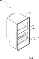
- the humidity adjusting system (100) is configured to be positioned in the thermally insulating case (80) of the cooling device (90) such as a refrigerator and/or a freezer as shown in Fig. 1 .
Landscapes
- Engineering & Computer Science (AREA)
- Chemical & Material Sciences (AREA)
- Combustion & Propulsion (AREA)
- Physics & Mathematics (AREA)
- Mechanical Engineering (AREA)
- Thermal Sciences (AREA)
- General Engineering & Computer Science (AREA)
- Cold Air Circulating Systems And Constructional Details In Refrigerators (AREA)
- Devices For Warming Or Keeping Food Or Tableware Hot (AREA)
Abstract
Description
- The present invention relates to a humidity adjusting system according to preamble of
claim 1. - To a great extent, cooling method is a widely used process for preserving freshness, directly in the domestic refrigerator appliances with which all kitchens are equipped.
- Although the widespread use of cooling device for food preservation increases the life of fresh foods in the refrigerator, the amount of humidity in the reservoir medium is an essential parameter in conserving the freshness. Attention to the amount of humidity the food is exposed to can facilitate users to maintain freshness for the longest possible time. The diverse amount of humidity is required to retain items fresh for longer; that is to say, some require more humidity than others, and some are more sensitive to humidity.
- A prior art publication in the technical field of the invention may be referred to as
WO 2019/034371 A1 , which discloses a refrigerator comprising a cooler compartment, a crisper placed at the lower side of the cooler compartment, a crisper cover placed over the crisper and a humidity control mechanism mounted at the front of the crisper cover, having a rotary button enabling varying the amount of the humid air transmitted from the crisper to the internal environment of the cooler compartment. - Various humidity regulating system enables the flexibility of converting this insulating storage to either a high humidity or low humidity. Yet, such mechanisms must present reasonably various humidity levels, and need to be as cost effective and durable as possible. Storage containers such as drawer or crisper must achieve these desiderata while, advantageously, enabling the drawer to be sealed when closed and permitting the airflow to be required when open. Accordingly, the requirement to retain raw food's freshness in a compact system is still demanded.
- An object of the invention is to provide a humidity adjusting system configured to be used in a household appliance that allows users to adjust humidity level in more than one level so as to prolong the edible life of food.
- The present invention proposes a humidity adjusting system configured to be positioned in a cabinet of a household appliance, comprising an insulating cover for covering a storage container cavity so as to limit air passage from the thermally insulating case to the storage container; a frame positioned above the storage container wherein the frame has a central portion including a housing through which an actuator at least partly extends. Additionally, said humidity adjusting system further includes a connection plate which is disposed on the central portion wherein said connection plate has a fixing portion coupled to a receiving flange formed on the insulating cover for transmitting the actuator movement thereto; and guide channel which is arranged in the frame. The present invention allows the user more than one, particularly, three different humidity levels in a storage container to prolong the food expire date, thereby providing flexibility usage to the user in a cost-effective way.
- In a possible embodiment of the invention, the guide channel comprises an initial portion in which a pin is placed, a first routing portion, a first holding portion, a first restricting portion, a second routing portion, a second holding portion and a second restricting portion. That is, a first restricting portion and a second restricting portion are individually configured to limit the backward movement of the pin in the guide channel by the help of the inclined portion. Additionally, a first holding portion and a second holding portion are individually configured to at least partly accommodate the pin. Said guide channel arrangement provides easy of manufacture and unique durable operation modes.
- In a possible embodiment, the actuator is configured to move in a direction parallel to the horizontal plane of the cooling device. Thus, solid and durable assembly of the actuator is provided. Just as the actuator does not require a rotary motion to operate makes it easier and simpler for the user to adjust the humidity, transmitting the force applied is performed in a simple manner.
- In a possible embodiment, the insulating cover further comprises at least one engagement element detachably attached to an inner liner of thermally insulating case. Accordingly, a cover housing is configured as a recess provided in the inner liner which is inclined with respect to the axis force applied on the actuator. In a possible embodiment, the insulating cover has a first position which obstructs an aperture between the insulating cover and the storage container, a second position which partially opens the aperture and a third position in which the insulating cover remains at least partially in contact with the storage compartment. Thus, insulating cover is able to move in more than one axis and be located in more than one position which provides a wider gap or cavity or aperture between the insulating cover and the frame; moreover, the cavity therebetween plays an essential role as an air passage to conserve the freshness.
- In a possible embodiment, the actuator further comprises at least one latching housing configured to match at least one connection protrusion which is arranged in the connection plate. In another possible embodiment, an actuation lever is formed to protrude from actuator. These arrangements of actuator provide durable assembly and eliminate possible waggling troubles.
- In a possible embodiment, the pin includes a contact cap associated with the actuator and a longitudinal bracing configured to extend therefrom in a direction to perpendicular to the guide channel. Thus, expected life of an item pin is guided in guide channel part efficiently. Establishing the pin in said configuration that operates securely in the guide channel increases the life of the pin and the guide channel, thereby reducing the necessity for technical service.
- In a possible embodiment, the central portion has an abutment unit which is in communication with a loaded resilient member. The resilient member is abutted against at least one seat, more notably, two seats so as to restrict an axial forward movement. Thus, the position of the resilient member is accurately defined and possible waggling issue is eliminated.
- In a possible embodiment of the invention, the frame further comprises at least one coupling projection which fits on a lateral surface of the connection plate for fixing the connection plate thereto. This fixing process minimizes operational problems such as vibration and sagging that may occur during the operation of the actuator, that is to say, fixing the frame to the connection plate via coupling projection thereof constitute a stable arrangement.
- In a possible embodiment of the invention, the humidity adjusting system further comprises a display unit which matches an indicator hook arranged on the connection, thereby illustrating the degree of humidity corresponding to the position of the actuator.
- In a possible embodiment of the invention, the storage container is sized and shaped as a drawer, in particular a crisper drawer. By having the insulating cover closed, water vapor is held in the drawer or in the crisper and the moisture retains therein. Besides adjusting humidity, at least one crisper or a drawer also present the opportunity to separate foods. Drawers are storage areas such as that present a more humid environment than the rest of the interior which is intended for accommodating foods and is bounded by walls.
- In another possible embodiment, a cooling device comprising said humidity adjusting system is provided. In this context, the cooling device can be a refrigerator, a freezer or a fridge-freezer combination device.
- The accompanying drawings are given solely for the purpose of exemplifying the invention whose advantages over prior art were outlined above and will be explained in detail hereinafter:
-
Fig. 1 shows a cooling device comprising the humidity adjusting system according to a possible embodiment of the present invention. -
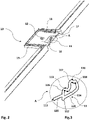
Fig. 2 shows a perspective view of the frame according to a possible embodiment of the present invention. -
Fig. 3 shows a detailed view of the guide channel according to a possible embodiment of the present invention. -
Fig. 4 shows a bottom perspective view of the connection plate according to a possible embodiment of the present invention. -
Fig. 5 shows an upper perspective view of the connection plate according to a possible embodiment of the present invention. -
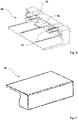
Fig. 6 shows a rear perspective view of the actuator according to a possible embodiment of the present invention. -
Fig. 7 shows a front view of the actuator according to a possible embodiment of the present invention. -
Fig. 8 shows an exploded perspective view of a possible embodiment of the invention having a frame, a connection plate and an actuator. -
Fig. 9 shows a bottom view ofFig. 8 illustrating the connection between the connection plate and the frame. -
Fig. 10 shows a perspective view of the insulating cover according to a possible embodiment of the present invention. -
Fig. 11 shows a perspective view of the display unit according to a possible embodiment of the present invention. -
Fig. 12 shows a perspective view of the resilient member according to a possible embodiment of the present invention. -
Fig. 13 shows a perspective view of the pin according to a possible embodiment of the present invention. -
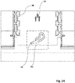
Fig. 14 shows an upper view of the frame, connection plate and the pin according to a possible embodiment of the present invention wherein the pin is in the initial portion of the guide channel. -
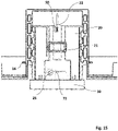
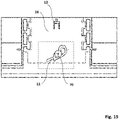
Fig. 15 shows a bottom view of the humidity adjusting system according to a possible embodiment of the present invention wherein the pin is in the initial portion of the guide channel. -
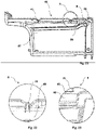
Fig. 16 shows a lateral view of the humidity adjusting system according to a possible embodiment of the present invention wherein the pin is in the initial portion of the guide channel. -
Fig. 17 shows an enlarged view of Detail A taken fromFIG. 16 wherein Detail A illustrates the connection between the insulating cover and the inner liner according to a possible embodiment of the present invention wherein the pin is in the initial portion of the guide channel. -
Fig. 18 shows an enlarged view of Detail B taken fromFIG. 16 wherein Detail B illustrates the connections between the insulating cover, frame, connection plate and the actuator according to a possible embodiment of the present invention wherein the pin is in the initial portion of the guide channel. -
Fig. 19 shows an upper view of the frame, connection plate and the pin according to a possible embodiment of the present invention wherein the pin is located at the first holding portion of the guide channel. -
Fig. 20 shows a bottom view of the humidity adjusting system according to a possible embodiment of the present invention wherein the pin is located at the first holding portion of the guide channel. -
Fig. 21 shows a lateral view of the humidity adjusting system according to a possible embodiment of the present invention wherein the pin is located at the first holding portion of the guide channel. -
Fig. 22 shows an enlarged view of Detail A taken fromFIG. 21 wherein Detail A illustrates the connection between the insulating cover and the inner liner according to a possible embodiment of the present invention wherein the pin is located at the first holding portion of the guide channel. -
Fig. 23 shows an enlarged view of Detail B taken fromFIG. 21 wherein Detail B illustrates the connections between the insulating cover, frame, connection plate and the actuator according to a possible embodiment of the present invention wherein the pin is located at the first holding portion of the guide channel. -
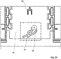
Fig. 24 shows an upper view of the frame, connection plate and the pin according to a possible embodiment of the present invention wherein the pin is located at the second holding portion of the guide channel. -
Fig. 25 shows a bottom view of the humidity adjusting system according to a possible embodiment of the present invention wherein the pin is located at the second holding portion of the guide channel. -
Fig. 26 shows a lateral view of the humidity adjusting system according to a possible embodiment of the present invention wherein the pin is located at the second holding portion of the guide channel. -
Fig. 27 shows an enlarged view of Detail A taken fromFIG. 27 wherein Detail A illustrates the connection between the insulating cover and the inner liner according to a possible embodiment of the present invention wherein the pin is located at the second holding portion of the guide channel. -
Fig. 28 shows an enlarged view of Detail B taken fromFIG. 27 wherein Detail B illustrates the connections between the insulating cover, frame, connection plate and the actuator according to a possible embodiment of the present invention wherein the pin is located at the second holding portion of the guide channel. - Hereinafter, various possible embodiments of the present invention will be described in detail with reference to the accompanying drawings which are given solely for the purpose of exemplifying embodiments according to the present invention. The list of reference numerals used in the appended drawings are provided at the end of this section.
- The present invention relates to a humidity adjusting system (100) for a storage container (85) located within a thermally insulating case (80) of a cooling device (90).
- Referring to
Fig. 8 , said humidity adjusting system(100) comprises an insulating cover (40) for covering the storage container (85) cavity so as to limit air passage from the thermally insulating case (80) to the storage container (85); a frame (10) positioned above the storage container (85) wherein the frame (10) has a central portion (16) including a housing (17) through which an actuator (30) at least partly extends as illustrated inFig. 2 , a connection plate (20) which is disposed on the central portion (16) as illustrated inFig. 9 . Said connection plate (20) has a fixing portion (21) coupled to a receiving flange (43) formed on the insulating cover (40) for transmitting the actuator (30) movement thereto and a connection groove (23) which is in communication with a corresponding protrusion arranged in the actuator (30) as depicted inFig. 4 and Fig. 5 . Said frame (10) further comprises a guide channel (11) which is arranged therein. Moreover the guide channel (11) is a monolithic with the frame (10) and has substantially predetermined width and a degree of curvature. - In a possible embodiment of the invention, the guide channel (11) has more than one edges, some of which have a curved shapes, particularly, convex and/or concave shapes.
- In a possible embodiment of the invention, the guide channel (11) has more than one bending portions, wherein said bending portions has at least one convex shape and/or at least one concave shape.
- In a possible embodiment of the invention, the guide channel (11) has both concave inner edges and convex inner edges, wherein said edges are configured and dimensioned to at least partially guide a pin (70).
- Referring now to the
Fig. 2 and 3 , the guide channel (11) comprises an initial portion (112) in which the pin (70) is placed, a first routing portion (113), a first holding portion (114), a first restricting portion (115), a second routing portion (116), a second holding portion (117) and a second restricting portion (118). That is, the first restricting portion (115) and the second restricting portion (118) are individually configured to limit the backward movement of the pin (70) in the guide channel (11) by the help of the inclined portion. Additionally, the first holding portion (114) and the second holding portion (117) are individually configured to at least partly accommodate the pin (70). - In an possible embodiment of the invention, not only the first restricting portion (115) and the second restricting portion (118) but also the first routing portion (113) and the second routing portion (116) are of substantially concave shape. In contrast, both the first holding portion (114) and the second holding portion (117) are of substantially convex shape.
- Referring again to the embodiment illustrated in
Fig. 3 , the guide channel (11) further includes a first tubular portion (119) and a second tubular portion (120). An end which is proximal to the initial portion (112) of the first tubular portion (119) is closer to the initial portion (112) with respect to an end proximal to the initial portion (112) of the second tubular portion (120). The end of the second tubular portion (120) is located at a distance and height that the pin (70) advancing to return to the initial portion (112) along the first tubular portion (119) can not enter the second tubular portion (120). - In a possible embodiment of the invention, referring again to
Fig. 3 , the guide channel (11) comprises a setting portion (111) which is aligned with a pin mounting slot (25) located on the connection plate (20). Indeed, the pin (70) is mounted to the humidity adjusting system (100) through the pin mounting slot (25) as shown inFig. 5 . Thus, durable assembly of the pin (70) is provided in a cost-effective way which decreases the requirements of experienced assembly technicians. - Referring to
Fig. 2 andFig. 6 , the frame (10) further comprises at least one coupling projection (13) which fits on a lateral surface (24) of the connection plate (20) for fixing the connection plate (20) thereto. This fixing process decreases the operational issues, that is to say, fixing the frame (10) to the connection plate (20) via the coupling projection (13) constitutes a stable arrangement. - According to the present invention there is also provided a central portion (16) comprising an abutment unit (12) which is in communication with a loaded resilient member (60). Said resilient member (60) is configured as a biasing member which biases the pin (70) to be at a predetermined position wherein said biasing member is formed of a spring as depicted in
Fig. 12 . One end of the spring is engaged with the abutment unit (12) of the central portion (16), and the other end thereof is engaged with the pin (70). As the pin (70) moves through the guide channel (11), the spring presses the pin (70) to return to the initial portion (112) at each stage. - According to various possible embodiments, the actuator (30) is configured to move in a direction parallel to the horizontal plane of the cooling device (90) as illustrated in
Fig. 7 . The actuator (30) further comprises at least one latching housing (31) configured to match at least one connection protrusion (27) which is arranged in the connection plate (20), a connection recess (32), a supporting part (33) configured as rib and an actuation lever (34) formed to protrude from the actuator (30) so as to provide durable assembly. - As illustrated in
Fig. 10 , the insulating cover (40) further comprises at least one engagement element (41) detachably attached to an inner liner (81) of the thermally insulating case (80). Accordingly an attachment slot (82) provided in the inner liner (81) is configured as a recess which is inclined with respect to the axis force applied on the actuator (30). Said inclined attachment slot (82) allows the insulating cover (40) to establish an aperture (86) in more than one axis. Hence, said arrangement ensures a favourable environment that prolongs the edible life of food. - In accordance with an another aspect of the invention; the insulating cover (40) has a first position (45) which obstructs the aperture (86) between the insulating cover (40) and the storage container (85) as illustrated in
Fig. 16 wherein the pin is in the initial portion of the guide channel. In that,Fig.17 illustrates an enlarged view of Detail A which shows the connection between the insulating cover and the inner liner.Fig. 18 illustrates a view of Detail B which illustrates the connections between the insulating cover, frame, connection plate and the actuator. Moreover as illustrated inFig. 21 ., the insulating cover (40) has a second position (46) which partially opens the aperture (86) wherein the pin is located at the first holding portion of the guide channel.Fig. 22 illustrates an enlarged view of Detail A which shows the connection between the insulating cover and the inner liner.Fig. 23 illustrates an enlarged view of Detail B which shows the connections between the insulating cover, frame, connection plate and the actuator. Moreover, as illustrated inFig. 26 ., the insulating cover (40) has a third position (47) in which the insulating cover (40) remains at least partially in contact with the storage container (85) wherein the pin is located at the second holding portion of the guide channel.Fig. 27 shows an enlarged view of Detail A which illustrates the connection between the insulating cover and the inner liner.Fig. 28 illustrates an enlarged view of Detail B which illustrates the connections between the insulating cover, frame, connection plate and the actuator. Consequently, the humidity level of the storage container (85) can be adjustable at least three different stages, such as low, middle and high. - Referring to
Fig. 13 , the pin (70) comprises a contact cap (72) associated with the actuator (30) and a longitudinal bracing (71) configured to extend from the contact cap (72) in a direction to perpendicular to the guide channel (11). - In an exemplary embodiment, the pin (70) is configured to move in the guide channel (11) when a predetermined level of force is applied thereto.
- The humidity adjusting system (100) offers an operation mechanism that includes three different positions of the actuator (30) to provide different humidity settings. To exemplify, the movement of system components is triggered which results in a first displacement of the insulating cover (40) when a first force is applied to the actuator (30). That is to say, as a force in a direction parallel to the horizontal plane of the cooling device (90) is applied to the actuator (30), the actuator (30) transmits the movement to the connection plate (20) via the connection protrusion (27) that matches the latching housing (31). By the movement of the connection plate (20) in the direction parallel to the horizontal plane of the cooling device (90), the pin (70) located in the setting portion (111) as depicted in
Fig. 14 and15 commences to advance upon the guide channel (11) and this movement pursues until the pin (70) touches the first routing portion (113). Thanks to the concave curvature of the first routing portion (113) and the inclined attachment slot (82), the direction of movement is converted into a multiaxis movement and therefore the pin (70) moves along an inclined plane and accommodates in the first holding portion (114). The position of the pin (70), as can be seen inFig. 19 and20 , corresponds the second position (46) of the insulating cover (40) as depicted inFig. 21 .
As a force which is acted on the actuator (30) exceeds the force provided by the first holding portion (114), the pin (70) commences to advance upon the guide channel (11). This movement pursues until the pin (70) touches the second routing portion (116). The direction of movement is converted into a multiaxis movement by means of the concave curvature of the second routing portion (116), therefore the pin (70) moves along an inclined plane and accommodates in the second holding portion (117). The position of the pin (70), as can be seen inFig. 24 and25 , corresponds the third position (47) of the insulating cover (40) as depicted inFig. 22 . - An additional force is applied to the actuator (30) in order to position the insulating cover (40) in first position (45) as depicted in
Fig. 16 . Owing to the biasing force of spring and the applied force on the actuator, the pin (70) overcomes the second restricting portion (118) and returns to the initial portion (112) via the first tubular portion (119). - According to the present invention there is also provided the humidity adjusting system (100) which is not spontaneously opened by the weak force (i.e, vibration) thereby achieving the stabile and durable arrangement.
- Referring now to the various aspects illustrated in
Fig. 4 ,Fig. 11 andFig. 25 , the humidity adjusting system (100) further comprises a display unit (50) which matches to an indicator hook (22) arranged on the connection plate (20) so as to illustrate the degree of humidity corresponding the position of the actuator (30). Said display unit (50) may include a number of displays and switches for displaying the moisture content in the storage container (85) thereby providing a user interface. - Referring to
Fig. 1 , the storage container (85) is sized and shaped as a drawer (87), in particular a crisper drawer. Drawers (87) are able to provide more humid environment than the rest of the thermally insulating case (80). By having the insulating cover (40), moisture is held in the drawer (87) and retains the vegetables fresher longer. In a possible embodiment, said drawer (87) is placed at the lower portion of the cooling device (90). In a possible embodiment, a shelf (88) is positioned above said drawer (87) enclosing the crisper cavity. - The humidity adjusting system (100) according to the present invention is configured to be positioned in the thermally insulating case (80) of the cooling device (90) such as a refrigerator and/or a freezer as shown in
Fig. 1 . -
- 10.
- Frame
11. Guide channel
111. Setting portion
112. Initial portion
113. First routing portion
114. First holding portion
115. First restricting portion
116. Second routing portion
117. Second holding portion
118. Second restricting portion
119. First tubular portion
120. Second tubular portion
12. Abutment unit
13. Coupling projection
16. Central portion
17. Housing - 20.
- Connection plate
21. Fixing portion
22. Indicator hook
23. Connection groove
24. Lateral surface
25. Pin mounting slot
27. Connection protrusion - 30.
- Actuator
31. Latching housing
32. Connection recess
34. Actuation lever - 40.
- Insulating cover
41. Engagement element
43. Receiving flange
45. First position
46. Second position
47. Third position - 50.
- Display unit
- 60.
- Resilient member
- 70.
- Pin
71. Longitudinal bracing
72. Contact cap - 80.
- Thermally insulating case
81. Inner liner
82. Attachment slot - 85.
- Storage container
- 86.
- Aperture
- 87
- Drawer
- 88
- Shelf
- 90.
- Cooling device
- 100.
- Humidity adjusting system
- A.
- Detail A
- B.
- Detail B
Claims (15)
- A humidity adjusting system (100) for a storage container (85) located within a thermally insulating case (80) of a cooling device (90), comprising:- an insulating cover (40) for covering the storage container (85) cavity so as to limit air passage from the thermally insulating case (80) to the storage container (85);- a frame (10) positioned above the storage container (85) wherein the frame (10) has a central portion (16) including a housing (17) through which an actuator (30) at least partly extends, characterized in that the humidity adjusting system (100) further comprises:- a connection plate (20) which is disposed on the central portion (16) wherein said connection plate (20) has a fixing portion (21) coupled to a receiving flange (43) formed on the insulating cover (40) for transmitting the actuator (30) movement thereto; and- a guide channel (11) which is arranged in the frame (10) wherein the guide channel (11) has an initial portion (112) in which a pin (70) is placed, a first holding portion (114) and a second holding portion (117) capable of retaining the pin (70) movements in the guide channel (11).
- The humidity adjusting system (100) according to claim 1; wherein the actuator (30) is configured to move in a direction parallel to the horizontal plane of the cooling device (90).
- The humidity adjusting system (100) according to claim 1; wherein the guide channel (11) further comprises, a first routing portion (113), a first restricting portion (115), a second routing portion (116), and a second restricting portion (118).
- The humidity adjusting system (100) according to claim 3, wherein the first restricting portion (115) and the second restricting portion (118) are individually configured to block the backward movement of the pin (70) in the guide channel (11).
- The humidity adjusting system (100) according to any one of the preceding claims, wherein the first holding portion (114) and the second holding portion (117) are individually configured to at least partly accommodate the pin.
- The humidity adjusting system (100) according to any of the preceding claims, wherein the insulating cover (40) comprises at least one engagement element (41) detachably attached to an inner liner (81) of thermally insulating case (80).
- The humidity adjusting system (100) according to any of the preceding claims, wherein the insulating cover (40) has a first position (45) which obstructs an aperture (86) between the insulating cover (40) and the storage container (85), and a second position (46) which partially opens the aperture (86) and a third position (47) in which the insulating cover (40) remains at least partially in contact with the storage container (85).
- The humidity adjusting system (100) according to any of the preceding claims, wherein the actuator (30) comprises at least one latching housing (31) configured to match at least one connection protrusion (27) which is arranged in the connection plate (20).
- The humidity adjusting system (100) according to any of the preceding claims, wherein an actuation lever (34) is formed to protrude from actuator (30).
- The humidity adjusting system (100) according to any of the preceding claims, wherein the pin (70) comprises a contact cap (72) associated with the actuator (30) and a longitudinal bracing (71) configured to extend from the contact cap (72) in a direction to perpendicular to the guide channel (11).
- The humidity adjusting system (100) according to any of the preceding claims, wherein the central portion (16) has an abutment unit (12) which is in communication with a loaded resilient member (60).
- The humidity adjusting system (100) according to any of the preceding claims, wherein a display unit (50) is configured to match to an indicator hook (22) arranged on the connection plate (20) so as to illustrate the degree of humidity corresponding the position of the actuator (30).
- The humidity adjusting system (100) according to any of the preceding claims, wherein the frame (10) comprises at least one coupling projection (13) which fits on a lateral surface (24) of the connection plate (20) for fixing the connection plate (20) thereto.
- The humidity adjusting system (100) according to any of the preceding claims, wherein the storage container (85) is sized and shaped as a drawer, in particular a crisper drawer.
- A cooling device (90) comprising the humidity regulating system (100) according one of the preceding claims.
Applications Claiming Priority (1)
| Application Number | Priority Date | Filing Date | Title |
|---|---|---|---|
| TR2020/15495A TR202015495A1 (en) | 2020-09-30 | 2020-09-30 | Humidity regulating system for a home appliance Humidity regulating system for a household appliance |
Publications (1)
| Publication Number | Publication Date |
|---|---|
| EP3978850A1 true EP3978850A1 (en) | 2022-04-06 |
Family
ID=77666373
Family Applications (1)
| Application Number | Title | Priority Date | Filing Date |
|---|---|---|---|
| EP21195527.3A Withdrawn EP3978850A1 (en) | 2020-09-30 | 2021-09-08 | A humidity adjusting system for a household appliance |
Country Status (3)
| Country | Link |
|---|---|
| EP (1) | EP3978850A1 (en) |
| CN (1) | CN216522616U (en) |
| TR (1) | TR202015495A1 (en) |
Citations (4)
| Publication number | Priority date | Publication date | Assignee | Title |
|---|---|---|---|---|
| WO2014206807A1 (en) * | 2013-06-27 | 2014-12-31 | BSH Bosch und Siemens Hausgeräte GmbH | Domestic refrigerator having a keep-fresh container and an operating element designed in the form of a push/push locking mechanism for moving a cover for the keep-fresh container |
| WO2015010980A1 (en) * | 2013-07-25 | 2015-01-29 | BSH Bosch und Siemens Hausgeräte GmbH | A home appliance having a container with adjustable humidity |
| WO2019034371A1 (en) | 2017-08-17 | 2019-02-21 | Arcelik Anonim Sirketi | Refrigerator comprising humidity controlled crisper |
| EP2662648B1 (en) * | 2012-05-10 | 2019-05-01 | Miele & Cie. KG | Cooled or air-conditioned cabinet |
-
2020
- 2020-09-30 TR TR2020/15495A patent/TR202015495A1/en unknown
-
2021
- 2021-09-08 EP EP21195527.3A patent/EP3978850A1/en not_active Withdrawn
- 2021-09-28 CN CN202122360461.8U patent/CN216522616U/en active Active
Patent Citations (4)
| Publication number | Priority date | Publication date | Assignee | Title |
|---|---|---|---|---|
| EP2662648B1 (en) * | 2012-05-10 | 2019-05-01 | Miele & Cie. KG | Cooled or air-conditioned cabinet |
| WO2014206807A1 (en) * | 2013-06-27 | 2014-12-31 | BSH Bosch und Siemens Hausgeräte GmbH | Domestic refrigerator having a keep-fresh container and an operating element designed in the form of a push/push locking mechanism for moving a cover for the keep-fresh container |
| WO2015010980A1 (en) * | 2013-07-25 | 2015-01-29 | BSH Bosch und Siemens Hausgeräte GmbH | A home appliance having a container with adjustable humidity |
| WO2019034371A1 (en) | 2017-08-17 | 2019-02-21 | Arcelik Anonim Sirketi | Refrigerator comprising humidity controlled crisper |
Also Published As
| Publication number | Publication date |
|---|---|
| CN216522616U (en) | 2022-05-13 |
| TR202015495A1 (en) | 2022-04-21 |
Similar Documents
| Publication | Publication Date | Title |
|---|---|---|
| KR101910655B1 (en) | Semi-auto closing apparatus and refrigerator having the same | |
| US10281194B2 (en) | Refrigerator | |
| EP1081448A2 (en) | Ice cube outlet cover assembly | |
| KR20060115581A (en) | Refrigerator with storage | |
| US8029081B2 (en) | Refrigerator | |
| CN107270614B (en) | Refrigerator with a door | |
| CN110425799B (en) | Refrigerator with a door | |
| US5941087A (en) | Refrigerator having an apparatus for preventing an air from flowing into the refrigerator | |
| US9696084B1 (en) | Light switch for door in door refrigerator | |
| US5540492A (en) | Snap-in humidity control for crisper pans | |
| AU2024287206A1 (en) | Storage structure for refrigerator appliance | |
| KR101526731B1 (en) | Hinge assembly for refrigerator door | |
| JP2017032264A (en) | refrigerator | |
| US20190003764A1 (en) | Household refrigeration device having an interior lighting system and method for producing a household refrigeration device | |
| KR101959558B1 (en) | Refrigerator and drawer type door thereof | |
| CN216522616U (en) | Humidity conditioning system for a household appliance and cooling device comprising such a system | |
| KR101652527B1 (en) | Refrigerator | |
| JP7720982B2 (en) | refrigerator | |
| KR101461961B1 (en) | Refrigerator | |
| EP1162420A1 (en) | Refrigerator | |
| US5611212A (en) | Refrigerator dual air flow control mechanism | |
| KR20150021827A (en) | Refrigerator | |
| JP6591361B2 (en) | refrigerator | |
| CN121631695A (en) | Carrying device and method with specific elastic buckle adapter | |
| KR100719252B1 (en) | Structure for assembling the cover assembly and humidity control knob of the vegetable box for refrigerator |
Legal Events
| Date | Code | Title | Description |
|---|---|---|---|
| PUAI | Public reference made under article 153(3) epc to a published international application that has entered the european phase |
Free format text: ORIGINAL CODE: 0009012 |
|
| STAA | Information on the status of an ep patent application or granted ep patent |
Free format text: STATUS: THE APPLICATION HAS BEEN PUBLISHED |
|
| AK | Designated contracting states |
Kind code of ref document: A1 Designated state(s): AL AT BE BG CH CY CZ DE DK EE ES FI FR GB GR HR HU IE IS IT LI LT LU LV MC MK MT NL NO PL PT RO RS SE SI SK SM TR |
|
| STAA | Information on the status of an ep patent application or granted ep patent |
Free format text: STATUS: REQUEST FOR EXAMINATION WAS MADE |
|
| 17P | Request for examination filed |
Effective date: 20221006 |
|
| RBV | Designated contracting states (corrected) |
Designated state(s): AL AT BE BG CH CY CZ DE DK EE ES FI FR GB GR HR HU IE IS IT LI LT LU LV MC MK MT NL NO PL PT RO RS SE SI SK SM TR |
|
| STAA | Information on the status of an ep patent application or granted ep patent |
Free format text: STATUS: EXAMINATION IS IN PROGRESS |
|
| 17Q | First examination report despatched |
Effective date: 20230221 |
|
| STAA | Information on the status of an ep patent application or granted ep patent |
Free format text: STATUS: THE APPLICATION HAS BEEN WITHDRAWN |
|
| 18W | Application withdrawn |
Effective date: 20230626 |