EP3978823A1 - Appareil portable generateur d'air chaud comprenant un systeme d'amortissement - Google Patents
Appareil portable generateur d'air chaud comprenant un systeme d'amortissement Download PDFInfo
- Publication number
- EP3978823A1 EP3978823A1 EP21197165.0A EP21197165A EP3978823A1 EP 3978823 A1 EP3978823 A1 EP 3978823A1 EP 21197165 A EP21197165 A EP 21197165A EP 3978823 A1 EP3978823 A1 EP 3978823A1
- Authority
- EP
- European Patent Office
- Prior art keywords
- handle
- plane
- housing
- symmetry
- shells
- Prior art date
- Legal status (The legal status is an assumption and is not a legal conclusion. Google has not performed a legal analysis and makes no representation as to the accuracy of the status listed.)
- Granted
Links
Images


Classifications
-
- F—MECHANICAL ENGINEERING; LIGHTING; HEATING; WEAPONS; BLASTING
- F23—COMBUSTION APPARATUS; COMBUSTION PROCESSES
- F23D—BURNERS
- F23D14/00—Burners for combustion of a gas, e.g. of a gas stored under pressure as a liquid
- F23D14/46—Details
- F23D14/48—Nozzles
- F23D14/52—Nozzles for torches; for blow-pipes
-
- F—MECHANICAL ENGINEERING; LIGHTING; HEATING; WEAPONS; BLASTING
- F23—COMBUSTION APPARATUS; COMBUSTION PROCESSES
- F23D—BURNERS
- F23D14/00—Burners for combustion of a gas, e.g. of a gas stored under pressure as a liquid
- F23D14/38—Torches, e.g. for brazing or heating
-
- F—MECHANICAL ENGINEERING; LIGHTING; HEATING; WEAPONS; BLASTING
- F23—COMBUSTION APPARATUS; COMBUSTION PROCESSES
- F23D—BURNERS
- F23D14/00—Burners for combustion of a gas, e.g. of a gas stored under pressure as a liquid
- F23D14/46—Details
- F23D14/465—Details for torches
-
- F—MECHANICAL ENGINEERING; LIGHTING; HEATING; WEAPONS; BLASTING
- F23—COMBUSTION APPARATUS; COMBUSTION PROCESSES
- F23D—BURNERS
- F23D14/00—Burners for combustion of a gas, e.g. of a gas stored under pressure as a liquid
- F23D14/46—Details
- F23D14/48—Nozzles
- F23D14/56—Nozzles for spreading the flame over an area, e.g. for desurfacing of solid material, for surface hardening or for heating workpieces
-
- F—MECHANICAL ENGINEERING; LIGHTING; HEATING; WEAPONS; BLASTING
- F24—HEATING; RANGES; VENTILATING
- F24H—FLUID HEATERS, e.g. WATER OR AIR HEATERS, HAVING HEAT-GENERATING MEANS, e.g. HEAT PUMPS, IN GENERAL
- F24H3/00—Air heaters
- F24H3/02—Air heaters with forced circulation
- F24H3/04—Air heaters with forced circulation the air being in direct contact with the heating medium, e.g. electric heating element
- F24H3/0488—Air heaters with forced circulation the air being in direct contact with the heating medium, e.g. electric heating element using fluid fuel
-
- F—MECHANICAL ENGINEERING; LIGHTING; HEATING; WEAPONS; BLASTING
- F23—COMBUSTION APPARATUS; COMBUSTION PROCESSES
- F23D—BURNERS
- F23D2207/00—Ignition devices associated with burner
-
- F—MECHANICAL ENGINEERING; LIGHTING; HEATING; WEAPONS; BLASTING
- F23—COMBUSTION APPARATUS; COMBUSTION PROCESSES
- F23D—BURNERS
- F23D2900/00—Special features of, or arrangements for burners using fluid fuels or solid fuels suspended in a carrier gas
- F23D2900/00012—Liquid or gas fuel burners with flames spread over a flat surface, either premix or non-premix type, e.g. "Flächenbrenner"
- F23D2900/00013—Liquid or gas fuel burners with flames spread over a flat surface, either premix or non-premix type, e.g. "Flächenbrenner" with means for spreading the flame in a fan or fishtail shape over a melting bath
-
- Y—GENERAL TAGGING OF NEW TECHNOLOGICAL DEVELOPMENTS; GENERAL TAGGING OF CROSS-SECTIONAL TECHNOLOGIES SPANNING OVER SEVERAL SECTIONS OF THE IPC; TECHNICAL SUBJECTS COVERED BY FORMER USPC CROSS-REFERENCE ART COLLECTIONS [XRACs] AND DIGESTS
- Y02—TECHNOLOGIES OR APPLICATIONS FOR MITIGATION OR ADAPTATION AGAINST CLIMATE CHANGE
- Y02B—CLIMATE CHANGE MITIGATION TECHNOLOGIES RELATED TO BUILDINGS, e.g. HOUSING, HOUSE APPLIANCES OR RELATED END-USER APPLICATIONS
- Y02B30/00—Energy efficient heating, ventilation or air conditioning [HVAC]
Definitions
- the present invention relates to a burner/hot air generator device, hereinafter referred to as a device, which can be used, in particular but not exclusively, for the low-temperature heating of plastic film, for example polyethylene film, with a view to their shrinkage at means of a gas stream from the combustion of combustible gas such as propane and air or for laying thermoplastic material on the floor.
- a device which can be used, in particular but not exclusively, for the low-temperature heating of plastic film, for example polyethylene film, with a view to their shrinkage at means of a gas stream from the combustion of combustible gas such as propane and air or for laying thermoplastic material on the floor.
- combustible gas such as propane and air or for laying thermoplastic material on the floor.
- a shrink gun is essentially composed of a power supply controlled by a trigger to feed a Venturi, from an external source of gas, for example LPG, under a pressure greater than atmospheric pressure.
- a flammable “atmospheric gas-air” mixture forms in the Venturi and ends up in a combustion chamber, where it is burned.
- the gas mixture thus formed is ignited at the terminals of a spark plug by a spark whose electrical energy is produced by a piezoelectric igniter located inside the gun and actuated when the trigger is pressed.
- the Venturi and the combustion chamber together form a substantially tube-shaped body.
- the upstream of the tube forms an air intake for the Venturi.
- the downstream forms a diffuser for the hot gases produced by the device.
- the tube is generally formed in two parts; a first part forms the Venturi, the second part forms the diffuser and serves as a combustion chamber.
- the diffuser is attached and assembled on the Venturi, by interlocking or screwing.
- a first object of the invention is to propose a body that is more robust and simpler to manufacture.
- a retraction gun like all hand-held devices, is subject to heavy loads and regularly suffers falls to the ground.
- a second object of the invention is to provide a device whose resistance to shocks, in particular in the event of a fall, is improved.
- a portable hot air generator device comprises a body mainly formed of two substantially symmetrical blanks with respect to a plane of symmetry, each blank being formed from a single piece of stamped sheet metal and comprising a first part, of semi-circular section, which forms a wall of a Venturi and a second part extending this first part forwards and which forms a diffuser.
- each blank comprises at the top and bottom, where the blanks meet on the plane of symmetry, flat edges parallel to the plane.
- the blanks are assembled with a dry joint.
- a portable hot air generator device comprises a handle and a body which extends along a main axis horizontal and substantially symmetrical relative to a vertical longitudinal plane and, in addition, a damping system between the handle and the body, so that the handle does not have direct contact with the body.
- the system can comprise at least one shock absorber, preferably two shock absorbers, each shock absorber comprising a housing, a cleat and a damping material, the housing being formed in the handle, the cleat being integral with the body, and, the material forming an elastic grip for one end of the cleat in the housing, at a distance from the walls of this housing.
- the cleat advantageously comprises a rod which extends vertically downward from the body and a crossbar at a distal end of the rod, the housing comprising an opening for the passage with play of the rod.
- the handle comprises two shells that are substantially symmetrical with each other relative to the plane of symmetry, each of the shells forming a laterally open part of the housing.
- the handle may comprise two shells substantially symmetrical to each other relative to the plane of symmetry, each of these shells comprising ribs, perpendicular to the plane of symmetry, the damping system comprising a layer of damping material placed on a crest ribs, between the body and the shell.
- the figures illustrate a hot air generator device 1, in two different embodiments.
- a hot air generator device is portable, that is to say it can be held in the hand, like a pistol, of which it has substantially the shape. It can be used, but not exclusively, for the low-temperature heating of plastic films, for example polyethylene film, with a view to their retraction by means of a stream of hot air originating from the combustion of a fuel gas.
- a fuel gas such as propane and air, or for laying thermoplastic material on the floor.
- It can also be used for thermal weeding; in particular in the latter case, it can be equipped with an extension.
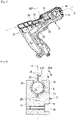
- FIG. 1 A first embodiment of such a device 1 is illustrated in figures 1 and 2 .
- Such a device is generally substantially symmetrical relative to a plane P and has a main axis X.
- the terms top, bottom, front, rear make it possible to describe the device by considering it in a position such that the plane P is vertical and the main axis X is horizontal, the hot air produced by the device being expelled towards the front of the device.
- the device 1 is shown in elevation and in longitudinal section along the plane of symmetry P.
- the device 1 mainly comprises a handle 2 and a body 3.
- the body and the handle are substantially rigid.
- the body has substantially the shape of a tube of revolution around the main axis X, extended by a flattened part serving as a diffuser.
- the device further comprises a damping system comprising two shock absorbers 4.
- Each damper comprises a housing 11, a cleat 12 and a damping material 13.
- the housing 11 is formed in the handle 2.
- the housing 11 comprises an opening 14, upwards.
- the cleat 12 is integral with the body 3 and extends downwards from this body, through the opening 14, into the housing 11, without contact with the shells 6.
- the damping material 13 isolates the cleat from the walls of the housing 11, and maintains the cleat in the housing.
- the cleat has an inverted "T" shape, the rod 16 of which extends from the body 3 through the opening 14, and a transverse bar 17 is embedded in the damping material 13.
- the housing 11 has a width L11 and a height H11 respectively greater than the width L17 and the height H17 of the bar 17, so that the bar 17 is sufficiently surrounded by material 13, without contact with the handle 2.
- the opening 14 has a width L14 greater than the width L16 of the rod 16, so as to guarantee sufficient clearance J between the walls of the opening 14 and the rod 16.
- the width L17 of the bar 17 is greater than the width L14 of the opening 14, so that the damper ensures a positive fixing of the body on the handle, that is to say without risk that the body will detach from the handle, even in the event of degradation of the material 13.
- the material 13 is an elastomer.
- the handle 2 is formed of two shells 6 substantially symmetrical with each other relative to the plane of symmetry P. They are fixed to each other by a system of screws 19.
- the housing 11 is formed by the assembly of the two shells, so that before this assembly the housing is in two laterally open parts.
- the bar 17 of the cleat 12 can be introduced into one of the parts, before assembly of the shells 6. After assembly of the shells, the bar 17 is trapped in the housing, thus ensuring the positive fixing of the body on the handle.
- FIG. 6 illustrate a second embodiment for a hot air generator device 1 according to the invention. This second embodiment will be described in that it differs from the first embodiment, previously described.
- the body 3 is mainly formed of two blanks 20 symmetrical to each other relative to the plane of symmetry P.
- Each blank is formed from a single piece of stamped sheet metal. It comprises a first part 21 of semi-circular section, of revolution around the longitudinal axis X; it forms a wall of the Venturi 23.
- a second part 22 extends the first forward, flattening and widening, from back to front; it forms a wall of the diffuser 24.
- Each blank 20 comprises, at the top and bottom, where the blanks meet on the plane of symmetry P, flat edges 26 parallel to the plane P.
- the edges 26 sufficiently wide, form between them a dry joint guaranteeing sufficient sealing around the gas flow which passes longitudinally through the body 3.
- each blank In the lower part, between the flat edges, each blank forms an arch 27, of revolution around a secondary axis X27, substantially vertical and perpendicular to the main axis X.
- a plug 33 illustrated in figure 5 , is intended to be arranged between the vaults to pass therein, with sealing, a wire electrically supplying a spark plug from a piezoelectric igniter 32; the spark plug and the wire are not shown in the figures.
- the handle 2 comprises two shells 6 assembled together by a screw system 19.
- each shell 6 comprises a grid of ribs 31, substantially perpendicular to the plane of symmetry P. These ribs have the primary functions of forming the transverse walls of each shell 6 and ensuring sufficient rigidity.
- the device 1 comprises a damping system between the body 3 and the handle 2.
- This system comprises a layer 34 of damping material glued to the crest of the ribs 31, in the upper part of each hull.
- Layer 34 has a substantially constant thickness E34, measured in a transverse plane.
- Preferably layer 34 is made of elastomer.
- the layer 34 provides an elastic interface between the handle 2 and the body 3, both on the tubular part 23,24 and on the flat edges, without the body being in contact with any of the shells 6. Pressure exerted by the layer 34 on the flat edges 26 ensures sufficient sealing between the flat edges 26, even with a dry joint.
- the shells partially fold over the first part 21 of the body 3, so that after assembly of the shells together, they provide positive attachment of the body to the handle.
- the blanks can be assembled by welding or gluing.
- the body can be made in one piece, for example by molding.
- the number of dampers may vary depending on the shape of the diffuser.
- each "cleat” can be a ply of the body sheet; this fold can form a tab, which engages in the damping material.
- a shock absorber can also, for example, take the form of a ring that surrounds the body, so that there is no need for a cleat to hold it there.
Landscapes
- Engineering & Computer Science (AREA)
- Chemical & Material Sciences (AREA)
- Combustion & Propulsion (AREA)
- Mechanical Engineering (AREA)
- General Engineering & Computer Science (AREA)
- Physics & Mathematics (AREA)
- Thermal Sciences (AREA)
- Vibration Dampers (AREA)
- Portable Nailing Machines And Staplers (AREA)
- Buffer Packaging (AREA)
- Thermotherapy And Cooling Therapy Devices (AREA)
Abstract
Description
- La présente invention concerne un appareil brûleur/générateur d'air chaud, ci-après nommé appareil, utilisable, notamment mais non exclusivement, au chauffage à basse température de film de matière plastique, par exemple de film de polyéthylène en vue de leur rétraction au moyen d'un flux gazeux provenant de la combustion d'un gaz combustible tel que du propane et de l'air ou pour la pose de matériau thermoplastique au sol. Ces appareils sont généralement connus sous le nom de pistolet de rétraction.
- Un pistolet de rétraction est composé essentiellement d'une alimentation commandée par une gâchette pour alimenter un Venturi, à partir d'une source externe de gaz, par exemple du GPL, sous une pression supérieure à la pression atmosphérique. Un mélange inflammable « gaz-air atmosphérique » se forme dans le Venturi et débouche dans une chambre de combustion, où il est brûlé. L'allumage du mélange gazeux ainsi formé est réalisé aux bornes d'une bougie par une étincelle dont l'énergie électrique est produite par un allumeur piézoélectrique situé à l'intérieur du pistolet et actionné lors de l'enfoncement de la gâchette.
- Le Venturi et la chambre de combustion forment ensemble un corps sensiblement en forme de tube. L'amont du tube forme une prise d'air pour le Venturi. L'aval forme un diffuseur pour les gaz chauds produits par l'appareil.
- Les différentes fonctions remplies par ce tube imposent des changements de section et de forme qui le rendent complexe à réaliser. Ainsi, le tube est généralement formé en deux parties ; une première partie forme le Venturi, la deuxième partie forme le diffuseur et sert de chambre de combustion. Le diffuseur est rapporté et assemblé sur le Venturi, par emboitement ou vissage.
- Cette disposition demande de nombreuses manipulations lors de la fabrication de l'appareil et le rend fragile lors de son utilisation.
- Ainsi, un premier but de l'invention est de proposer un corps plus robuste et plus simple à fabriquer.
- En outre, un pistolet de rétractation, comme tous les appareils à main, sont fortement sollicités et subissent régulièrement des chutes au sol.
- Ainsi, un deuxième but de l'invention est de proposer un appareil dont la résistance aux chocs, notamment en cas de chute, est améliorée.
- Selon un premier objet de l'invention, un appareil portable générateur d'air chaud comprend un corps principalement formé de deux flans sensiblement symétriques entre eux relativement à un plan de symétrie, chaque flan étant formé d'une seule pièce en tôle emboutie et comprenant une première partie, de section semi circulaire, qui forme une paroi d'un Venturi et une deuxième partie prolongeant cette première partie vers l'avant et qui forme un diffuseur.
- Avantageusement, chaque flan comprend en haut et en bas, là où les flans se rejoignent sur le plan de symétrie, des bords plats parallèles au plan. De préférence, les flans sont assemblés à joint sec.
- Selon un deuxième objet de l'invention, un appareil portable générateur d'air chaud comprend une poignée et un corps qui s'étend selon un axe principal horizontal et sensiblement symétrique relativement à un plan longitudinal vertical et, en outre, un système d'amortissement entre la poignée et le corps, de sorte que la poignée n'a pas de contact direct avec le corps.
- Le système peut comprendre au moins un amortisseur, de préférence deux amortisseurs, chaque amortisseur comprenant un logement, un taquet et une matière amortisseuse, le logement étant formé dans la poignée, le taquet étant solidaire du corps, et, la matière formant une prise élastique pour une extrémité du taquet dans le logement, à distance des parois de ce logement. Le taquet comprend avantageusement une tige qui s'étend verticalement vers le bas depuis le corps et une barre transversale à une extrémité distale de la tige, le logement comprenant une ouverture pour le passage avec jeu de la tige. De préférence, la poignée comprend deux coques sensiblement symétriques l'une de l'autre relativement au plan de symétrie, chacune des coques formant une partie du logement ouverte latéralement.
- La poignée peut comprendre deux coques sensiblement symétriques l'une de l'autre relativement au plan de symétrie, chacune de ces coques comprenant des nervures, perpendiculaires au plan de symétrie, le système d'amortissement comprenant une couche de matière amortisseuse disposée sur une crête des nervures, entre le corps et la coque.
- Des modes de réalisation et des variantes seront décrits ci-après, à titre d'exemples non limitatifs, avec référence aux dessins annexés dans lesquels :
- [
Fig. 1 ] est une vue d'un appareil générateur d'air chaud, dans un premier mode de réalisation de l'invention, en coupe schématique en élévation longitudinale, selon un plan de coupe I-I de lafigure 2 ; - [
Fig. 2 ] est une vue en coupe schématique transversale de l'appareil de lafigure 1 , selon un plan de coupe II-II de lafigure 1 ; - [
Fig. 3 ] est une vue schématique en élévation longitudinale d'un appareil générateur d'air chaud, dans un deuxième mode de réalisation de l'invention où, notamment, le corps est réalisé en deux flans sensiblement symétriques entre eux ; - [
Fig. 4 ] est une vue en perspective d'un flan pour former un corps de l'appareil de lafigure 3 ; - [
Fig. 5 ] est une vue en perspective de la poignée de l'appareil de lafigure 3 ; et, - [
Fig. 6 ] est une vue en coupe transversale schématique de l'appareil desfigures 3 à 4 . - Les figures illustrent un appareil générateur d'air chaud 1, dans deux modes de réalisation différents. Un tel appareil est portable, c'est-à-dire qu'il peut être tenu à la main, comme un pistolet dont il a sensiblement la forme. Il est utilisable, mais non exclusivement, au chauffage à basse température de films de matière plastique, par exemple de film en polyéthylène, en vue de leur rétractation au moyen d'un flux d'air chaud provenant de la combustion d'un gaz carburant tel que le propane et l'air, ou pour la pose d'un matériau thermoplastique au sol. Il peut aussi être utilisé pour du désherbage thermique ; notamment dans ce dernier cas, il peut être équipé d'un prolongateur.
- Un premier mode de réalisation d'un tel appareil 1 est illustré aux
figures 1 et 2 . Un tel appareil est généralement sensiblement symétrique relativement à un plan P et comporte un axe principal X. Dans la description, notamment les termes haut, bas, avant, arrière permettent de décrire l'appareil en le considérant dans une position telle que le plan P est vertical et l'axe principal X est horizontal, l'air chaud produit par l'appareil étant expulsé vers l'avant de l'appareil. - A la
figure 1 , l'appareil 1 est représenté en élévation et en coupe longitudinale selon le plan de symétrie P. - L'appareil 1 comprend principalement une poignée 2 et un corps 3. Le corps et la poignée sont sensiblement rigides. Le corps a sensiblement la forme d'un tube de révolution autour de l'axe principal X, prolongé par une partie aplatie servant de diffuseur. L'appareil comprend en outre un système d'amortissement comprenant deux amortisseurs 4.
- Chaque amortisseur comprend un logement 11, un taquet 12 et une matière amortisseuse 13.
- Le logement 11 est formé dans la poignée 2. Le logement 11 comprend une ouverture 14, vers le haut. Le taquet 12 est solidaire du corps 3 et s'étend vers le bas depuis ce corps, au travers de l'ouverture 14, jusque dans le logement 11, sans contact avec les coques 6. La matière amortisseuse 13 isole le taquet des parois du logement 11, et maintient le taquet dans le logement.
- Dans l'exemple illustré, le taquet a une forme de « T » inversé dont la tige 16 s'étend depuis le corps 3 au travers de l'ouverture 14, et une barre transversale 17 est noyée dans la matière amortisseuse 13. Comme illustré à la
figure 2 , en coupe transversale, le logement 11 a une largeur L11 et une hauteur H11 respectivement supérieures à la largeur L17 et à la hauteur H17 de la barre 17, de sorte que la barre 17 est suffisamment entourée de matière 13, sans contact avec la poignée 2. En outre, l'ouverture 14 a une largeur L14 supérieure à la largeur L16 de la tige 16, de façon à garantir un jeu J suffisant, entre les parois de l'ouverture 14 et la tige 16. Comme illustré à lafigure 1 , il en va de même pour les dimensions longitudinales. Aussi, un jeu J suffisant est maintenu entre le corps 3 et d'autres parties 2A de la poignée 2. De plus, la largeur L17 de la barre 17 est supérieure à la largeur L14 de l'ouverture 14, de sorte que l'amortisseur assure une fixation positive du corps sur la poignée, c'est-à-dire sans risque que le corps ne se détache de la poignée, même en cas de dégradation de la matière 13. De préférence, la matière 13 est un élastomère. - Dans l'exemple illustré, la poignée 2 est formée de deux coques 6 sensiblement symétriques entre elles relativement au plan de symétrie P. Elles sont fixées l'une à l'autre par un système de vis 19. Le logement 11 est formé par l'assemblage des deux coques, de sorte qu'avant cet assemblage le logement est en deux parties ouvertes latéralement. Ainsi, la barre 17 du taquet 12 peut être introduite dans l'une des parties, avant assemblage des coques 6. Après assemblage des coques, la barre 17 se trouve prisonnière du logement, assurant ainsi la fixation positive du corps sur la poignée.
- Les
figures 3 à 6 illustrent un deuxième mode de réalisation pour un appareil générateur d'air chaud 1 selon l'invention. Ce deuxième mode de réalisation sera décrit en ce qu'il diffère du premier mode de réalisation, précédemment décrit. - Dans cet exemple, comme particulièrement illustré aux
figures 3, 4 et5 , le corps 3 est principalement formé de deux flans 20 symétriques l'un de l'autre relativement au plan de symétrie P. Chaque flan est formé d'une seule pièce en tôle emboutie. Il comprend une première partie 21 de section semi circulaire, de révolution autour de l'axe longitudinal X ; elle forme une paroi du Venturi 23. Une deuxième partie 22 prolonge la première vers l'avant, en s'écrasant et en s'évasant, d'arrière en avant ; elle forme une paroi du diffuseur 24. - Chaque flan 20 comprend, en haut et en bas, là où les flans se rejoignent sur le plan de symétrie P, des bords plats 26 parallèles au plan P. Lorsque les flans sont maintenus plaqués l'un contre l'autre, les bords 26, suffisamment larges, forment entre eux un joint sec garantissant une étanchéité suffisante autour du flux gazeux qui traverse longitudinalement le corps 3.
- En partie basse, entre les bords plats, chaque flan forme une voûte 27, de révolution autour d'un axe secondaire X27, sensiblement vertical et perpendiculaire à l'axe principal X. Un bouchon 33, illustré à la
figure 5 , est prévu pour être disposé entre les voutes pour y faire passer, avec étanchéité, un fil alimentant électriquement une bougie d'allumage depuis un allumeur piézoélectrique 32 ; la bougie et le fil ne sont pas représentés aux figures. - Comme particulièrement illustré aux
figures 5 et 6 , ainsi que dans le premier mode de réalisation, la poignée 2 comprend deux coques 6 assemblées entre elles par un système de vis 19. Dans le deuxième mode de réalisation, chaque coque 6 comprend un cadrillage de nervures 31, sensiblement perpendiculaires au plan de symétrie P. Ces nervures ont pour fonctions premières de former les parois transversales de chaque coque 6 et d'en assurer une rigidité suffisante. - De même que dans le premier mode de réalisation, l'appareil 1 comprend un système d'amortissement entre le corps 3 et la poignée 2. Ce système comprend une couche 34 de matière amortisseuse collée sur la crête des nervures 31, dans la partie supérieure de chaque coque. La couche 34 a une épaisseur E34, mesurée dans un plan transversal, sensiblement constante. De préférence la couche 34 est en élastomère.
- Comme illustré à la
figure 6 , la couche 34 assure une interface élastique entre la poignée 2 et le corps 3, à la fois sur la partie tubulaire 23,24 et sur les bords plats, sans que le corps ne soit en contact avec aucune des coques 6. Une pression exercée par la couche 34 sur les bords plats 26 permet d'assurer entre les bords plats 26 une étanchéité suffisante, même à joint sec. - Par ailleurs, les coques se replient partiellement au-dessus de la première partie 21 du corps 3, de sorte qu'après assemblage des coques entre elles, elles assurent une fixation positive du corps sur la poignée.
- Bien sûr, l'invention n'est pas limitée aux exemples qui viennent d'être décrits. Au contraire, l'invention est définie par les revendications qui suivent.
- Il apparaîtra en effet à l'homme de l'art que diverses modifications peuvent être apportées aux modes de réalisation décrits ci-dessus, à la lumière de l'enseignement qui vient de lui être divulgué.
- Ainsi, au lieu d'un joint sec, les flans peuvent être assemblés par soudage ou par collage.
- Aussi, le corps peut être réalisé d'une seule pièce, par exemple par moulage.
- Le nombre d'amortisseurs peut varier en fonction de la forme du diffuseur.
- Aussi, chaque "taquets" peut être un pli de la tôle du corps ; ce pli peut formant une patte, qui vient en prise dans la matière amortisseuse. Un amortisseur peut aussi, par exemple, prendre la forme d'une bague qui entoure le corps, de sorte qu'il n'y a pas besoin de taquet pour l'y maintenir.
- Un générateur selon l'invention présente de nombreux avantages par rapport à un générateur de l'art antérieur ; notamment :
- il a un coût de fabrication notablement réduit ; et,
- il a une résistance améliorée. En désolidarisant la poignée du corps, il évite que la poignée casse, notamment lors d'une chute sur le corps, dont l'impact se transmettrait directement à une poignée en plastique.
Claims (11)
- Appareil portable générateur d'air chaud (1) comprenant une poignée (2) et un corps (3) qui s'étend selon un axe principal horizontal (X) et sensiblement symétrique relativement à un plan longitudinal vertical (P), caractérisé en ce qu'il comprend en outre un système d'amortissement (4, 34) entre ladite poignée et ledit corps, de sorte que la poignée n'a pas de contact direct avec le corps.
- Appareil selon la revendication 1, caractérisé en ce que le système d'amortissement comprend au moins un amortisseur (4), chaque amortisseur comprenant un logement (11), un taquet (12) et une matière amortisseuse (13), ledit logement étant formé dans la poignée, ledit taquet étant solidaire du corps, et, ladite matière formant une prise élastique pour une extrémité (17) du taquet dans le logement, à distance des parois dudit logement.
- Appareil selon la revendication 2, caractérisé en ce que le taquet (12) comprend une tige (16) qui s'étend verticalement vers le bas depuis le corps (3) et une barre transversale (17) à une extrémité distale de ladite tige, et en ce que le logement comprend une ouverture (14) pour le passage avec jeu (J) de la tige.
- Appareil selon la revendication 2, caractérisé en ce que le taquet est un pli de la tôle du corps qui forme une patte venant en prise dans la matière amortisseuse.
- Appareil selon l'une des revendications 2 à 4, caractérisé en ce que la poignée comprend deux coques (6) sensiblement symétriques l'une de l'autre relativement au plan de symétrie (P), chacune desdites coques formant une partie du logement ouverte latéralement.
- Appareil selon l'une des revendications 2 à 5, caractérisé en ce qu'il comprend deux amortisseurs.
- Appareil selon la revendication 1, caractérisé en ce que le système d'amortissement comprend au moins un amortisseur ayant la forme d'une bague qui entoure le corps.
- Appareil selon la revendication 1, caractérisé en ce que la poignée (6) comprend deux coques (6) sensiblement symétriques l'une de l'autre relativement au plan de symétrie (P), chacune desdites coques comprenant des nervures (31), perpendiculaires audit plan de symétrie (P), le système d'amortissement comprenant une couche (34) de matière amortisseuse disposée sur une crête desdites nervures, entre le corps et ladite coque.
- Appareil selon la revendication 1, caractérisé en ce que le corps est principalement formé de deux flans (20) sensiblement symétriques entre eux relativement au plan de symétrie (P), chaque flan étant formé d'une seule pièce en tôle emboutie et comprenant une première partie (21) de section semi circulaire, de révolution autour de l'axe longitudinal X, qui forme une paroi d'un Venturi (23) et une deuxième partie (22) prolongeant ladite première partie vers l'avant qui forme un diffuseur (24).
- Appareil selon la revendication 9, caractérisé en ce que chaque flan comprend en haut et en bas, là où les flans (20) se rejoignent sur le plan de symétrie (P), des bords plats (26) parallèles au plan (P).
- Appareil selon la revendication 10, caractérisé en ce que les flans sont assemblés à joint sec.
Applications Claiming Priority (1)
| Application Number | Priority Date | Filing Date | Title |
|---|---|---|---|
| FR2009978A FR3114640B1 (fr) | 2020-09-30 | 2020-09-30 | Appareil portable generateur d’air chaud comprenant un systeme d’amortissement. |
Publications (2)
| Publication Number | Publication Date |
|---|---|
| EP3978823A1 true EP3978823A1 (fr) | 2022-04-06 |
| EP3978823B1 EP3978823B1 (fr) | 2024-09-11 |
Family
ID=73498052
Family Applications (1)
| Application Number | Title | Priority Date | Filing Date |
|---|---|---|---|
| EP21197165.0A Active EP3978823B1 (fr) | 2020-09-30 | 2021-09-16 | Appareil portable generateur d'air chaud comprenant un systeme d'amortissement |
Country Status (3)
| Country | Link |
|---|---|
| US (1) | US20220099292A1 (fr) |
| EP (1) | EP3978823B1 (fr) |
| FR (1) | FR3114640B1 (fr) |
Citations (3)
| Publication number | Priority date | Publication date | Assignee | Title |
|---|---|---|---|---|
| DE2822192A1 (de) * | 1978-05-20 | 1979-11-22 | Msk Verpackung Syst Gmbh | Handschrumpfgeraet fuer die erzeugung eines heissluftstrahls zum schrumpfen von kunststoffolien o.dgl. |
| EP0841518A2 (fr) * | 1996-11-08 | 1998-05-13 | Shrinkfast Corporation | Pistolet de projection à chaud avec une pompe à jet de haute performance et des parts à changement rapide |
| EP1795803A2 (fr) * | 2005-12-06 | 2007-06-13 | Guilbert Express | Outil à main à combustion de gaz modulaire |
Family Cites Families (10)
| Publication number | Priority date | Publication date | Assignee | Title |
|---|---|---|---|---|
| US930636A (en) * | 1907-10-09 | 1909-08-10 | John J Wescott | Vehicle connection. |
| US1404876A (en) * | 1920-05-27 | 1922-01-31 | Int Motor Co | Cushion connection for vehicle construction |
| US1703765A (en) * | 1924-12-13 | 1929-02-26 | Cort Walker J | Flexible connecter |
| US2043442A (en) * | 1935-03-21 | 1936-06-09 | James E Mcneil | Tool holder |
| US2577269A (en) * | 1949-11-16 | 1951-12-04 | Bell & Richardson Inc De | Flameless hot gas torch |
| GB2030280B (en) * | 1977-09-29 | 1982-03-10 | Hadland & Olive Ltd | Heat gun |
| US4596921A (en) * | 1984-05-22 | 1986-06-24 | Hersh Alan S | Low noise hand-held hairdryer |
| FR2714580B1 (fr) * | 1993-12-30 | 1996-02-09 | Seb Sa | Accessoire de coiffure pour appareil à sécher les cheveux. |
| US5841943A (en) * | 1997-04-25 | 1998-11-24 | Soundesign, Llc | Ducted flow hair dryer with multiple impellers |
| US20100064542A1 (en) * | 2008-09-15 | 2010-03-18 | Hamilton Beach Brands, Inc. | Hair drying apparatus |
-
2020
- 2020-09-30 FR FR2009978A patent/FR3114640B1/fr active Active
-
2021
- 2021-09-16 EP EP21197165.0A patent/EP3978823B1/fr active Active
- 2021-09-30 US US17/490,207 patent/US20220099292A1/en not_active Abandoned
Patent Citations (3)
| Publication number | Priority date | Publication date | Assignee | Title |
|---|---|---|---|---|
| DE2822192A1 (de) * | 1978-05-20 | 1979-11-22 | Msk Verpackung Syst Gmbh | Handschrumpfgeraet fuer die erzeugung eines heissluftstrahls zum schrumpfen von kunststoffolien o.dgl. |
| EP0841518A2 (fr) * | 1996-11-08 | 1998-05-13 | Shrinkfast Corporation | Pistolet de projection à chaud avec une pompe à jet de haute performance et des parts à changement rapide |
| EP1795803A2 (fr) * | 2005-12-06 | 2007-06-13 | Guilbert Express | Outil à main à combustion de gaz modulaire |
Also Published As
| Publication number | Publication date |
|---|---|
| FR3114640B1 (fr) | 2022-11-18 |
| US20220099292A1 (en) | 2022-03-31 |
| FR3114640A1 (fr) | 2022-04-01 |
| EP3978823B1 (fr) | 2024-09-11 |
Similar Documents
| Publication | Publication Date | Title |
|---|---|---|
| EP0125965B1 (fr) | Brûleur pour combustibles gazeux à systèmes d'allumage et de sécurité incorporés | |
| CA2679015C (fr) | Generateur d'air chaud | |
| EP0235055A1 (fr) | Appareil à brûleur à gaz pour l'application d'un adhésif thermofusible | |
| CN117677798A (zh) | 便携式燃气炉具 | |
| EP3978823B1 (fr) | Appareil portable generateur d'air chaud comprenant un systeme d'amortissement | |
| FR2606834A1 (fr) | Dispositif de chauffage pour collecteur d'admission de moteur a allumage par compression | |
| KR20100049840A (ko) | 토치 램프 | |
| EP1941207B1 (fr) | Bruleur/generateur d'air chaud a allumage interne | |
| FR2975169B1 (fr) | Bruleur generateur d'air chaud avec allumeur interchangeable. | |
| FR2975168A1 (fr) | Appareil generateur d'air chaud a allumage ameliore. | |
| EP1795803B1 (fr) | Outil à main à combustion de gaz modulaire | |
| FR2621076A1 (fr) | Structure de chambre de precombustion pour moteur a combustion interne | |
| WO2010136259A1 (fr) | Outil a main a detendeur de gaz incorpore avec systeme de controle de temperature du detendeur | |
| FR3113717A1 (fr) | Dispositif d’injection de gaz pour un générateur d’air chaud | |
| EP4162848B1 (fr) | Allume-feu électrique | |
| BE1006424A3 (fr) | Outil a main a dispositif d'allumage de gaz. | |
| FR2977125A1 (fr) | Desherbeur thermique a gaz sans flamme visible | |
| FR2654806A1 (fr) | Appareil de chauffage au gaz par rayonnement infrarouge. | |
| FR2479326A1 (fr) | Dispositif de precombustion rapporte dans un moteur diesel | |
| FR2884594A1 (fr) | Bruleur/generateur d'air chaud a allumage interne | |
| EP0093047A2 (fr) | Buse à allumage par étincelles pour chalumeau | |
| FR3114639A1 (fr) | Mode de fixation amélioré pour une bougie d’allumage d’un générateur d’air chaud. | |
| FR2921276A1 (fr) | Dispositif de vaporisation d'un liquide | |
| FR2847184A1 (fr) | Fer a souder a allumage a pierre | |
| BE470201A (fr) |
Legal Events
| Date | Code | Title | Description |
|---|---|---|---|
| PUAI | Public reference made under article 153(3) epc to a published international application that has entered the european phase |
Free format text: ORIGINAL CODE: 0009012 |
|
| STAA | Information on the status of an ep patent application or granted ep patent |
Free format text: STATUS: EXAMINATION IS IN PROGRESS |
|
| 17P | Request for examination filed |
Effective date: 20210916 |
|
| AK | Designated contracting states |
Kind code of ref document: A1 Designated state(s): AL AT BE BG CH CY CZ DE DK EE ES FI FR GB GR HR HU IE IS IT LI LT LU LV MC MK MT NL NO PL PT RO RS SE SI SK SM TR |
|
| GRAP | Despatch of communication of intention to grant a patent |
Free format text: ORIGINAL CODE: EPIDOSNIGR1 |
|
| STAA | Information on the status of an ep patent application or granted ep patent |
Free format text: STATUS: GRANT OF PATENT IS INTENDED |
|
| INTG | Intention to grant announced |
Effective date: 20240403 |
|
| RIN1 | Information on inventor provided before grant (corrected) |
Inventor name: CLEMENT, FRANCOIS |
|
| GRAS | Grant fee paid |
Free format text: ORIGINAL CODE: EPIDOSNIGR3 |
|
| GRAA | (expected) grant |
Free format text: ORIGINAL CODE: 0009210 |
|
| STAA | Information on the status of an ep patent application or granted ep patent |
Free format text: STATUS: THE PATENT HAS BEEN GRANTED |
|
| AK | Designated contracting states |
Kind code of ref document: B1 Designated state(s): AL AT BE BG CH CY CZ DE DK EE ES FI FR GB GR HR HU IE IS IT LI LT LU LV MC MK MT NL NO PL PT RO RS SE SI SK SM TR |
|
| REG | Reference to a national code |
Ref country code: GB Ref legal event code: FG4D Free format text: NOT ENGLISH |
|
| REG | Reference to a national code |
Ref country code: CH Ref legal event code: EP |
|
| REG | Reference to a national code |
Ref country code: DE Ref legal event code: R096 Ref document number: 602021018569 Country of ref document: DE |
|
| REG | Reference to a national code |
Ref country code: IE Ref legal event code: FG4D Free format text: LANGUAGE OF EP DOCUMENT: FRENCH |
|
| REG | Reference to a national code |
Ref country code: LT Ref legal event code: MG9D |
|
| PG25 | Lapsed in a contracting state [announced via postgrant information from national office to epo] |
Ref country code: NO Free format text: LAPSE BECAUSE OF FAILURE TO SUBMIT A TRANSLATION OF THE DESCRIPTION OR TO PAY THE FEE WITHIN THE PRESCRIBED TIME-LIMIT Effective date: 20241211 |
|
| REG | Reference to a national code |
Ref country code: NL Ref legal event code: MP Effective date: 20240911 |
|
| PG25 | Lapsed in a contracting state [announced via postgrant information from national office to epo] |
Ref country code: GR Free format text: LAPSE BECAUSE OF FAILURE TO SUBMIT A TRANSLATION OF THE DESCRIPTION OR TO PAY THE FEE WITHIN THE PRESCRIBED TIME-LIMIT Effective date: 20241212 Ref country code: FI Free format text: LAPSE BECAUSE OF FAILURE TO SUBMIT A TRANSLATION OF THE DESCRIPTION OR TO PAY THE FEE WITHIN THE PRESCRIBED TIME-LIMIT Effective date: 20240911 |
|
| PG25 | Lapsed in a contracting state [announced via postgrant information from national office to epo] |
Ref country code: BG Free format text: LAPSE BECAUSE OF FAILURE TO SUBMIT A TRANSLATION OF THE DESCRIPTION OR TO PAY THE FEE WITHIN THE PRESCRIBED TIME-LIMIT Effective date: 20240911 |
|
| PG25 | Lapsed in a contracting state [announced via postgrant information from national office to epo] |
Ref country code: LV Free format text: LAPSE BECAUSE OF FAILURE TO SUBMIT A TRANSLATION OF THE DESCRIPTION OR TO PAY THE FEE WITHIN THE PRESCRIBED TIME-LIMIT Effective date: 20240911 |
|
| PG25 | Lapsed in a contracting state [announced via postgrant information from national office to epo] |
Ref country code: HR Free format text: LAPSE BECAUSE OF FAILURE TO SUBMIT A TRANSLATION OF THE DESCRIPTION OR TO PAY THE FEE WITHIN THE PRESCRIBED TIME-LIMIT Effective date: 20240911 |
|
| PG25 | Lapsed in a contracting state [announced via postgrant information from national office to epo] |
Ref country code: ES Free format text: LAPSE BECAUSE OF FAILURE TO SUBMIT A TRANSLATION OF THE DESCRIPTION OR TO PAY THE FEE WITHIN THE PRESCRIBED TIME-LIMIT Effective date: 20240911 Ref country code: RS Free format text: LAPSE BECAUSE OF FAILURE TO SUBMIT A TRANSLATION OF THE DESCRIPTION OR TO PAY THE FEE WITHIN THE PRESCRIBED TIME-LIMIT Effective date: 20241211 |
|
| PG25 | Lapsed in a contracting state [announced via postgrant information from national office to epo] |
Ref country code: RS Free format text: LAPSE BECAUSE OF FAILURE TO SUBMIT A TRANSLATION OF THE DESCRIPTION OR TO PAY THE FEE WITHIN THE PRESCRIBED TIME-LIMIT Effective date: 20241211 Ref country code: NO Free format text: LAPSE BECAUSE OF FAILURE TO SUBMIT A TRANSLATION OF THE DESCRIPTION OR TO PAY THE FEE WITHIN THE PRESCRIBED TIME-LIMIT Effective date: 20241211 Ref country code: LV Free format text: LAPSE BECAUSE OF FAILURE TO SUBMIT A TRANSLATION OF THE DESCRIPTION OR TO PAY THE FEE WITHIN THE PRESCRIBED TIME-LIMIT Effective date: 20240911 Ref country code: HR Free format text: LAPSE BECAUSE OF FAILURE TO SUBMIT A TRANSLATION OF THE DESCRIPTION OR TO PAY THE FEE WITHIN THE PRESCRIBED TIME-LIMIT Effective date: 20240911 Ref country code: GR Free format text: LAPSE BECAUSE OF FAILURE TO SUBMIT A TRANSLATION OF THE DESCRIPTION OR TO PAY THE FEE WITHIN THE PRESCRIBED TIME-LIMIT Effective date: 20241212 Ref country code: FI Free format text: LAPSE BECAUSE OF FAILURE TO SUBMIT A TRANSLATION OF THE DESCRIPTION OR TO PAY THE FEE WITHIN THE PRESCRIBED TIME-LIMIT Effective date: 20240911 Ref country code: ES Free format text: LAPSE BECAUSE OF FAILURE TO SUBMIT A TRANSLATION OF THE DESCRIPTION OR TO PAY THE FEE WITHIN THE PRESCRIBED TIME-LIMIT Effective date: 20240911 Ref country code: BG Free format text: LAPSE BECAUSE OF FAILURE TO SUBMIT A TRANSLATION OF THE DESCRIPTION OR TO PAY THE FEE WITHIN THE PRESCRIBED TIME-LIMIT Effective date: 20240911 |
|
| REG | Reference to a national code |
Ref country code: AT Ref legal event code: MK05 Ref document number: 1723026 Country of ref document: AT Kind code of ref document: T Effective date: 20240911 |
|
| PG25 | Lapsed in a contracting state [announced via postgrant information from national office to epo] |
Ref country code: NL Free format text: LAPSE BECAUSE OF FAILURE TO SUBMIT A TRANSLATION OF THE DESCRIPTION OR TO PAY THE FEE WITHIN THE PRESCRIBED TIME-LIMIT Effective date: 20240911 |
|
| PG25 | Lapsed in a contracting state [announced via postgrant information from national office to epo] |
Ref country code: IS Free format text: LAPSE BECAUSE OF FAILURE TO SUBMIT A TRANSLATION OF THE DESCRIPTION OR TO PAY THE FEE WITHIN THE PRESCRIBED TIME-LIMIT Effective date: 20250111 Ref country code: PT Free format text: LAPSE BECAUSE OF FAILURE TO SUBMIT A TRANSLATION OF THE DESCRIPTION OR TO PAY THE FEE WITHIN THE PRESCRIBED TIME-LIMIT Effective date: 20250113 |
|
| PG25 | Lapsed in a contracting state [announced via postgrant information from national office to epo] |
Ref country code: RO Free format text: LAPSE BECAUSE OF FAILURE TO SUBMIT A TRANSLATION OF THE DESCRIPTION OR TO PAY THE FEE WITHIN THE PRESCRIBED TIME-LIMIT Effective date: 20240911 Ref country code: SM Free format text: LAPSE BECAUSE OF FAILURE TO SUBMIT A TRANSLATION OF THE DESCRIPTION OR TO PAY THE FEE WITHIN THE PRESCRIBED TIME-LIMIT Effective date: 20240911 |
|
| PG25 | Lapsed in a contracting state [announced via postgrant information from national office to epo] |
Ref country code: EE Free format text: LAPSE BECAUSE OF FAILURE TO SUBMIT A TRANSLATION OF THE DESCRIPTION OR TO PAY THE FEE WITHIN THE PRESCRIBED TIME-LIMIT Effective date: 20240911 Ref country code: AT Free format text: LAPSE BECAUSE OF FAILURE TO SUBMIT A TRANSLATION OF THE DESCRIPTION OR TO PAY THE FEE WITHIN THE PRESCRIBED TIME-LIMIT Effective date: 20240911 |
|
| PG25 | Lapsed in a contracting state [announced via postgrant information from national office to epo] |
Ref country code: CZ Free format text: LAPSE BECAUSE OF FAILURE TO SUBMIT A TRANSLATION OF THE DESCRIPTION OR TO PAY THE FEE WITHIN THE PRESCRIBED TIME-LIMIT Effective date: 20240911 Ref country code: PL Free format text: LAPSE BECAUSE OF FAILURE TO SUBMIT A TRANSLATION OF THE DESCRIPTION OR TO PAY THE FEE WITHIN THE PRESCRIBED TIME-LIMIT Effective date: 20240911 |
|
| PG25 | Lapsed in a contracting state [announced via postgrant information from national office to epo] |
Ref country code: IT Free format text: LAPSE BECAUSE OF FAILURE TO SUBMIT A TRANSLATION OF THE DESCRIPTION OR TO PAY THE FEE WITHIN THE PRESCRIBED TIME-LIMIT Effective date: 20240911 Ref country code: SK Free format text: LAPSE BECAUSE OF FAILURE TO SUBMIT A TRANSLATION OF THE DESCRIPTION OR TO PAY THE FEE WITHIN THE PRESCRIBED TIME-LIMIT Effective date: 20240911 |
|
| REG | Reference to a national code |
Ref country code: CH Ref legal event code: PL |
|
| PG25 | Lapsed in a contracting state [announced via postgrant information from national office to epo] |
Ref country code: LU Free format text: LAPSE BECAUSE OF NON-PAYMENT OF DUE FEES Effective date: 20240916 |
|
| REG | Reference to a national code |
Ref country code: DE Ref legal event code: R097 Ref document number: 602021018569 Country of ref document: DE |
|
| PG25 | Lapsed in a contracting state [announced via postgrant information from national office to epo] |
Ref country code: MC Free format text: LAPSE BECAUSE OF FAILURE TO SUBMIT A TRANSLATION OF THE DESCRIPTION OR TO PAY THE FEE WITHIN THE PRESCRIBED TIME-LIMIT Effective date: 20240911 |
|
| PG25 | Lapsed in a contracting state [announced via postgrant information from national office to epo] |
Ref country code: DK Free format text: LAPSE BECAUSE OF FAILURE TO SUBMIT A TRANSLATION OF THE DESCRIPTION OR TO PAY THE FEE WITHIN THE PRESCRIBED TIME-LIMIT Effective date: 20240911 |
|
| REG | Reference to a national code |
Ref country code: BE Ref legal event code: MM Effective date: 20240930 |
|
| PG25 | Lapsed in a contracting state [announced via postgrant information from national office to epo] |
Ref country code: BE Free format text: LAPSE BECAUSE OF NON-PAYMENT OF DUE FEES Effective date: 20240930 |
|
| PLBE | No opposition filed within time limit |
Free format text: ORIGINAL CODE: 0009261 |
|
| STAA | Information on the status of an ep patent application or granted ep patent |
Free format text: STATUS: NO OPPOSITION FILED WITHIN TIME LIMIT |
|
| PG25 | Lapsed in a contracting state [announced via postgrant information from national office to epo] |
Ref country code: CH Free format text: LAPSE BECAUSE OF NON-PAYMENT OF DUE FEES Effective date: 20240930 |
|
| PG25 | Lapsed in a contracting state [announced via postgrant information from national office to epo] |
Ref country code: IE Free format text: LAPSE BECAUSE OF NON-PAYMENT OF DUE FEES Effective date: 20240916 |
|
| 26N | No opposition filed |
Effective date: 20250612 |
|
| PG25 | Lapsed in a contracting state [announced via postgrant information from national office to epo] |
Ref country code: SE Free format text: LAPSE BECAUSE OF FAILURE TO SUBMIT A TRANSLATION OF THE DESCRIPTION OR TO PAY THE FEE WITHIN THE PRESCRIBED TIME-LIMIT Effective date: 20240911 |
|
| PGFP | Annual fee paid to national office [announced via postgrant information from national office to epo] |
Ref country code: FR Payment date: 20250926 Year of fee payment: 5 |
|
| PGFP | Annual fee paid to national office [announced via postgrant information from national office to epo] |
Ref country code: DE Payment date: 20251029 Year of fee payment: 5 |
|
| PG25 | Lapsed in a contracting state [announced via postgrant information from national office to epo] |
Ref country code: CY Free format text: LAPSE BECAUSE OF FAILURE TO SUBMIT A TRANSLATION OF THE DESCRIPTION OR TO PAY THE FEE WITHIN THE PRESCRIBED TIME-LIMIT; INVALID AB INITIO Effective date: 20210916 |
|
| PG25 | Lapsed in a contracting state [announced via postgrant information from national office to epo] |
Ref country code: HU Free format text: LAPSE BECAUSE OF FAILURE TO SUBMIT A TRANSLATION OF THE DESCRIPTION OR TO PAY THE FEE WITHIN THE PRESCRIBED TIME-LIMIT; INVALID AB INITIO Effective date: 20210916 |
|
| GBPC | Gb: european patent ceased through non-payment of renewal fee |
Effective date: 20250916 |
|
| PG25 | Lapsed in a contracting state [announced via postgrant information from national office to epo] |
Ref country code: TR Free format text: LAPSE BECAUSE OF FAILURE TO SUBMIT A TRANSLATION OF THE DESCRIPTION OR TO PAY THE FEE WITHIN THE PRESCRIBED TIME-LIMIT Effective date: 20240911 |
|
| PG25 | Lapsed in a contracting state [announced via postgrant information from national office to epo] |
Ref country code: SI Free format text: LAPSE BECAUSE OF FAILURE TO SUBMIT A TRANSLATION OF THE DESCRIPTION OR TO PAY THE FEE WITHIN THE PRESCRIBED TIME-LIMIT Effective date: 20240911 |
|
| PG25 | Lapsed in a contracting state [announced via postgrant information from national office to epo] |
Ref country code: LT Free format text: LAPSE BECAUSE OF FAILURE TO SUBMIT A TRANSLATION OF THE DESCRIPTION OR TO PAY THE FEE WITHIN THE PRESCRIBED TIME-LIMIT Effective date: 20240911 |
|
| PG25 | Lapsed in a contracting state [announced via postgrant information from national office to epo] |
Ref country code: GB Free format text: LAPSE BECAUSE OF NON-PAYMENT OF DUE FEES Effective date: 20250916 |