EP3978779A1 - Rebound valve systems and methods - Google Patents
Rebound valve systems and methods Download PDFInfo
- Publication number
- EP3978779A1 EP3978779A1 EP21199161.7A EP21199161A EP3978779A1 EP 3978779 A1 EP3978779 A1 EP 3978779A1 EP 21199161 A EP21199161 A EP 21199161A EP 3978779 A1 EP3978779 A1 EP 3978779A1
- Authority
- EP
- European Patent Office
- Prior art keywords
- restrictor
- valve
- strut
- valves
- snubber
- Prior art date
- Legal status (The legal status is an assumption and is not a legal conclusion. Google has not performed a legal analysis and makes no representation as to the accuracy of the status listed.)
- Pending
Links
- 238000000034 method Methods 0.000 title description 8
- 230000035939 shock Effects 0.000 claims description 44
- 239000012530 fluid Substances 0.000 claims description 14
- 230000006835 compression Effects 0.000 claims description 11
- 238000007906 compression Methods 0.000 claims description 11
- 238000004891 communication Methods 0.000 claims description 3
- 239000007789 gas Substances 0.000 description 16
- 230000008901 benefit Effects 0.000 description 6
- 238000004519 manufacturing process Methods 0.000 description 4
- 230000007423 decrease Effects 0.000 description 3
- IJGRMHOSHXDMSA-UHFFFAOYSA-N Atomic nitrogen Chemical compound N#N IJGRMHOSHXDMSA-UHFFFAOYSA-N 0.000 description 2
- 230000008878 coupling Effects 0.000 description 2
- 238000010168 coupling process Methods 0.000 description 2
- 238000005859 coupling reaction Methods 0.000 description 2
- 238000013016 damping Methods 0.000 description 2
- 239000007788 liquid Substances 0.000 description 2
- 239000006096 absorbing agent Substances 0.000 description 1
- 230000009471 action Effects 0.000 description 1
- 230000006978 adaptation Effects 0.000 description 1
- 230000000712 assembly Effects 0.000 description 1
- 238000000429 assembly Methods 0.000 description 1
- 230000009286 beneficial effect Effects 0.000 description 1
- 230000005540 biological transmission Effects 0.000 description 1
- 238000010276 construction Methods 0.000 description 1
- 230000003247 decreasing effect Effects 0.000 description 1
- 238000004146 energy storage Methods 0.000 description 1
- 230000003993 interaction Effects 0.000 description 1
- 239000000463 material Substances 0.000 description 1
- 230000013011 mating Effects 0.000 description 1
- 239000000203 mixture Substances 0.000 description 1
- 229910052757 nitrogen Inorganic materials 0.000 description 1
- 230000008569 process Effects 0.000 description 1
- 238000010926 purge Methods 0.000 description 1
- 230000004044 response Effects 0.000 description 1
- 230000035945 sensitivity Effects 0.000 description 1
- 238000004513 sizing Methods 0.000 description 1
- 239000000725 suspension Substances 0.000 description 1
- 230000001052 transient effect Effects 0.000 description 1
- 230000007704 transition Effects 0.000 description 1
Images






Classifications
-
- F—MECHANICAL ENGINEERING; LIGHTING; HEATING; WEAPONS; BLASTING
- F16—ENGINEERING ELEMENTS AND UNITS; GENERAL MEASURES FOR PRODUCING AND MAINTAINING EFFECTIVE FUNCTIONING OF MACHINES OR INSTALLATIONS; THERMAL INSULATION IN GENERAL
- F16F—SPRINGS; SHOCK-ABSORBERS; MEANS FOR DAMPING VIBRATION
- F16F9/00—Springs, vibration-dampers, shock-absorbers, or similarly-constructed movement-dampers using a fluid or the equivalent as damping medium
- F16F9/06—Springs, vibration-dampers, shock-absorbers, or similarly-constructed movement-dampers using a fluid or the equivalent as damping medium using both gas and liquid
- F16F9/062—Bi-tubular units
-
- B—PERFORMING OPERATIONS; TRANSPORTING
- B64—AIRCRAFT; AVIATION; COSMONAUTICS
- B64C—AEROPLANES; HELICOPTERS
- B64C25/00—Alighting gear
- B64C25/32—Alighting gear characterised by elements which contact the ground or similar surface
- B64C25/58—Arrangements or adaptations of shock-absorbers or springs
- B64C25/60—Oleo legs
-
- F—MECHANICAL ENGINEERING; LIGHTING; HEATING; WEAPONS; BLASTING
- F16—ENGINEERING ELEMENTS AND UNITS; GENERAL MEASURES FOR PRODUCING AND MAINTAINING EFFECTIVE FUNCTIONING OF MACHINES OR INSTALLATIONS; THERMAL INSULATION IN GENERAL
- F16F—SPRINGS; SHOCK-ABSORBERS; MEANS FOR DAMPING VIBRATION
- F16F9/00—Springs, vibration-dampers, shock-absorbers, or similarly-constructed movement-dampers using a fluid or the equivalent as damping medium
-
- F—MECHANICAL ENGINEERING; LIGHTING; HEATING; WEAPONS; BLASTING
- F16—ENGINEERING ELEMENTS AND UNITS; GENERAL MEASURES FOR PRODUCING AND MAINTAINING EFFECTIVE FUNCTIONING OF MACHINES OR INSTALLATIONS; THERMAL INSULATION IN GENERAL
- F16F—SPRINGS; SHOCK-ABSORBERS; MEANS FOR DAMPING VIBRATION
- F16F9/00—Springs, vibration-dampers, shock-absorbers, or similarly-constructed movement-dampers using a fluid or the equivalent as damping medium
- F16F9/10—Springs, vibration-dampers, shock-absorbers, or similarly-constructed movement-dampers using a fluid or the equivalent as damping medium using liquid only; using a fluid of which the nature is immaterial
- F16F9/14—Devices with one or more members, e.g. pistons, vanes, moving to and fro in chambers and using throttling effect
- F16F9/16—Devices with one or more members, e.g. pistons, vanes, moving to and fro in chambers and using throttling effect involving only straight-line movement of the effective parts
- F16F9/18—Devices with one or more members, e.g. pistons, vanes, moving to and fro in chambers and using throttling effect involving only straight-line movement of the effective parts with a closed cylinder and a piston separating two or more working spaces therein
- F16F9/185—Bitubular units
-
- F—MECHANICAL ENGINEERING; LIGHTING; HEATING; WEAPONS; BLASTING
- F16—ENGINEERING ELEMENTS AND UNITS; GENERAL MEASURES FOR PRODUCING AND MAINTAINING EFFECTIVE FUNCTIONING OF MACHINES OR INSTALLATIONS; THERMAL INSULATION IN GENERAL
- F16F—SPRINGS; SHOCK-ABSORBERS; MEANS FOR DAMPING VIBRATION
- F16F9/00—Springs, vibration-dampers, shock-absorbers, or similarly-constructed movement-dampers using a fluid or the equivalent as damping medium
- F16F9/32—Details
- F16F9/34—Special valve constructions; Shape or construction of throttling passages
- F16F9/346—Throttling passages in the form of slots arranged in cylinder walls
- F16F9/3465—Slots having a variable section along their length
-
- F—MECHANICAL ENGINEERING; LIGHTING; HEATING; WEAPONS; BLASTING
- F16—ENGINEERING ELEMENTS AND UNITS; GENERAL MEASURES FOR PRODUCING AND MAINTAINING EFFECTIVE FUNCTIONING OF MACHINES OR INSTALLATIONS; THERMAL INSULATION IN GENERAL
- F16F—SPRINGS; SHOCK-ABSORBERS; MEANS FOR DAMPING VIBRATION
- F16F9/00—Springs, vibration-dampers, shock-absorbers, or similarly-constructed movement-dampers using a fluid or the equivalent as damping medium
- F16F9/32—Details
- F16F9/50—Special means providing automatic damping adjustment, i.e. self-adjustment of damping by particular sliding movements of a valve element, other than flexions or displacement of valve discs; Special means providing self-adjustment of spring characteristics
- F16F9/516—Special means providing automatic damping adjustment, i.e. self-adjustment of damping by particular sliding movements of a valve element, other than flexions or displacement of valve discs; Special means providing self-adjustment of spring characteristics resulting in the damping effects during contraction being different from the damping effects during extension, i.e. responsive to the direction of movement
-
- F—MECHANICAL ENGINEERING; LIGHTING; HEATING; WEAPONS; BLASTING
- F16—ENGINEERING ELEMENTS AND UNITS; GENERAL MEASURES FOR PRODUCING AND MAINTAINING EFFECTIVE FUNCTIONING OF MACHINES OR INSTALLATIONS; THERMAL INSULATION IN GENERAL
- F16F—SPRINGS; SHOCK-ABSORBERS; MEANS FOR DAMPING VIBRATION
- F16F2230/00—Purpose; Design features
- F16F2230/0052—Physically guiding or influencing
- F16F2230/0076—Pivoting
-
- F—MECHANICAL ENGINEERING; LIGHTING; HEATING; WEAPONS; BLASTING
- F16—ENGINEERING ELEMENTS AND UNITS; GENERAL MEASURES FOR PRODUCING AND MAINTAINING EFFECTIVE FUNCTIONING OF MACHINES OR INSTALLATIONS; THERMAL INSULATION IN GENERAL
- F16F—SPRINGS; SHOCK-ABSORBERS; MEANS FOR DAMPING VIBRATION
- F16F9/00—Springs, vibration-dampers, shock-absorbers, or similarly-constructed movement-dampers using a fluid or the equivalent as damping medium
- F16F9/32—Details
- F16F9/34—Special valve constructions; Shape or construction of throttling passages
Definitions
- the present disclosure relates generally to rebound valve systems and methods.
- the present disclosure relates to rebound valve systems and methods for use in a shock strut of a landing gear system.
- Shock absorbing devices are used in a wide variety of vehicle suspension systems for controlling motion of the vehicle and its tires with respect to the ground and for reducing transmission of transient forces from the ground to the vehicle.
- Shock absorbing struts are a common component in most aircraft landing gear assemblies. Shock struts control motion of the landing gear, and absorb and damp loads imposed on the gear during landing, taxiing, braking, and takeoff.
- a shock strut generally accomplishes these functions by compressing a fluid within a sealed chamber formed by hollow telescoping cylinders.
- the fluid generally includes both a gas and a liquid, such as hydraulic fluid or oil.
- One type of shock strut generally utilizes an "air-over-oil" arrangement wherein a trapped volume of gas is compressed as the shock strut is axially compressed, and a volume of oil is metered through an orifice.
- the gas acts as an energy storage device, similar to a spring, so that upon termination of a compressing force the shock strut returns to its original length.
- Shock struts also dissipate energy by passing the oil through the orifice so that as the shock absorber is compressed or extended, its rate of motion is limited by the damping action from the interaction of the orifice and the oil.
- a rebound valve system for a shock strut generally controls a strut out-stroke velocity to limit a piston bottoming impact load while allowing the extension velocity that is fast enough to maintain tire to ground contact during taxiing.
- the snubber assembly may comprise: a snubber having a snubber body with an inner diameter surface and an outer diameter surface, the snubber including a plurality of valve receptacles disposed in the outer diameter surface, the snubber including a plurality of radial apertures disposed through the snubber body, each radial aperture in the plurality of radial apertures disposed in a respective valve receptacle in the plurality of valve receptacles; and a plurality of restrictor valves, each restrictor valve in the plurality of restrictor valves disposed in a respective valve receptacle in the plurality of valve receptacles, each restrictor valve in the plurality of restrictor valves including an orifice disposed through a blade.
- the snubber assembly may further comprise a retaining ring, wherein the retaining ring couples the plurality of restrictor valves to the snubber body.
- the plurality of restrictor valves may be configured to pivot about the retaining ring.
- the snubber assembly may further comprise a plurality of seal valves disposed in a portion of the plurality of valve receptacles, wherein the plurality of restrictor valves are disposed in a remaining portion of the plurality of valve receptacles.
- the plurality of seal valves may include a first keying feature and the plurality of restrictor valves may include a second keying feature to prevent mis-assembly.
- Each restrictor valve in the plurality of restrictor valves may include a grip, the blade, and a shaft extending from the grip to the blade. The orifice may be disposed through the blade.
- the rebound valve system may comprise:
- each restrictor valve in the plurality of restrictor valves includes an orifice disposed through a blade.
- a fluid may be configured to flow from the rebound chamber through the orifice and a respective radial aperture in the plurality of radial apertures into the oil chamber during the extension of the strut piston.
- a flow of fluid may be configured to pivot the plurality of restrictor valves about a pivot axis to open the plurality of restrictor valves during the compression of the strut piston.
- the rebound valve system may further comprise a plurality of seal valves, wherein each seal valve in the plurality of seal valves is configured to seal a respective radial aperture in the plurality of radial apertures during the extension of the strut piston.
- the rebound valve system may further comprise a snubber disposed between the strut cylinder and the strut piston.
- the plurality of restrictor valves may be disposed between the snubber and the strut cylinder.
- the shock strut assembly may comprise: a strut cylinder; a strut piston, the strut cylinder configured to receive the strut piston, the strut piston defining an oil chamber; and a snubber assembly disposed between the strut cylinder and the strut piston, the snubber assembly comprising: a snubber having a plurality of valve receptacles disposed in an outer diameter surface of the snubber; and a plurality of restrictor valves, each restrictor valve disposed in a respective valve receptacle in the plurality of valve receptacles, each restrictor valve in the plurality of restrictor valves configured to open during a compression of the strut piston relative to the strut cylinder, and each restrictor valve configured to at least partially close during an extension of the strut piston.
- each restrictor valve includes a grip, a blade, and a shaft extending from the grip to the blade, and each restrictor valve is configured to pivot about the grip.
- the shock strut assembly may further comprise a plurality of seal valves disposed in a portion of the plurality of valve receptacles, wherein the plurality of restrictor valves are disposed in a remaining portion of the plurality of valve receptacles.
- the shock strut assembly may further comprise a retaining ring, wherein the plurality of restrictor valves are coupled to the retaining ring, and wherein the retaining ring is coupled to the snubber.
- the oil chamber may be in fluid communication with a rebound chamber through the plurality of restrictor valves, the rebound chamber defined between the strut piston and the strut cylinder.
- a flow of fluid may be configured to pivot the plurality of restrictor valves about a pivot axis to open the plurality of restrictor valves during the compression of the strut piston.
- a rebound valve system for a shock strut assembly is disclosed herein.
- the rebound valve system may be configured to meter oil to slow down a piston extension in the shock strut assembly, or the like.
- the rebound valve system may be configured to dampen the piston extension.
- Typical rebound valve systems may include slip rings, which may be difficult to manufacture, and/or may cause issues with assembly of the shock strut assembly.
- the rebound valve system disclosed herein may include a plurality of restrictor valves disposed circumferentially about a piston and/or a snubber of the shock strut assembly.
- the rebound valve system may further comprise a plurality of seal valves.
- the plurality of restrictor valves and the plurality of seal valves may be configured to transition from a closed position, or partially closed position, to allow a free flow of oil to a rebound chamber from a hydraulic chamber of the shock strut assembly. In various embodiments, the plurality of restrictor valves may allow metered flow from the rebound chamber to the hydraulic chamber when in a closed position.
- the shock strut assembly 100 may comprise a strut cylinder 110, a strut piston 120, a metering pin 140, an orifice support tube 150, and a rebound valve system 160.
- Strut piston 120 may be operatively coupled to strut cylinder 110 as described herein.
- Strut cylinder 110 may be configured to receive strut piston 120 in a manner that allows the two components to telescope together and absorb and/or dampen forces transmitted thereto.
- a liquid such as a hydraulic fluid and/or oil may be located within strut cylinder 110.
- a gas such as nitrogen or air, may also be located within strut cylinder 110.
- Strut cylinder 110 and strut piston 120 may, for example, be configured to seal such that fluid contained within strut cylinder 110 is prevented from leaking as strut piston 120 translates relative to strut cylinder 110.
- the metering pin 140 and the orifice support tube 150 may be positioned within primary chamber 130. The metering pin 140 may translate with strut piston 120.
- Shock strut assembly 100 may comprise a low pressure, primary chamber 130 in which oil and gas can mix.
- a volume of gas (also referred to herein as a primary chamber gas volume) 131 and a volume of oil (also referred to herein as an oil volume) 133 may be contained within primary chamber 130.
- a portion of primary chamber 130 may contain the primary chamber gas volume 131 and may be referred to as a primary gas chamber 132.
- the portion of primary chamber 130 containing the oil volume 133 may be referred to herein as an oil chamber 134.
- Dashed line 135 represents the level of oil volume 133, or the interface between the oil chamber 134 and the primary gas chamber 132.
- the oil volume 133 may be located below dashed line 135 and primary chamber gas volume 131 may be located above dashed line 135.
- the interface between the oil chamber 134 and the primary gas chamber 132 may move relative to primary chamber 130 depending on the position of strut piston 120 relative to strut cylinder 110.
- Shock strut assembly 100 may further comprise rebound chamber 136.
- the rebound chamber 136 is disposed between the strut cylinder 110 and an outer diameter surface of the strut piston 120. The rebound chamber 136 expands when the strut cylinder 110 is compressed, and the rebound chamber 136 contracts when the strut cylinder 110 extends.
- the rebound valve system 160 is configured to allow free flow into the rebound chamber 136. In various embodiments, the rebound valve system 160 is configured to prevent or minimize cavitation. When the strut piston 120 extends, the rebound valve system 160 is configured to close and oil flow out of the rebound chamber is restricted, or metered, by the rebound valve system 160. In various embodiments, the rebound valve system 160 is configured to control the extend rate and snub the strut piston 120 bottoming force at full extension.
- the shock strut assembly 100 further comprises an upper bearing assembly 170.
- the upper bearing assembly 170 is disposed adjacent to the rebound valve system 160.
- the rebound valve system 160 includes the strut piston 120, a snubber 210, and a plurality of restrictor valves 220.
- the snubber 210 is disposed radially outward of the strut piston 120, and the plurality restrictor valves 220 are disposed radially outward of the snubber 210.
- a rebound valve system 160 may exclude a snubber 210, and the restrictor valves may be operably coupled directly to the strut piston 120.
- having the snubber 210 may reduce manufacturing costs of the strut piston 120 and/or simplify assembly of the shock strut assembly 100 from FIG. 1 .
- the strut piston 120 comprises a plurality of radial apertures 122
- the snubber 210 comprises a plurality of radial apertures 212.
- the plurality of radial apertures 212 of the snubber 210 are aligned radially and axially with the plurality of radial apertures 122 of the strut piston 120.
- each radial aperture in the plurality of radial apertures 212 of the snubber 210 may be larger in diameter relative to a respective radial aperture in the plurality of radial apertures 122 of the strut piston.
- the snubber 210 may include looser tolerances for the plurality of radial apertures 212, reducing manufacturing costs and/or facilitating assembly of the shock strut assembly 100 from FIG. 1 .
- each restrictor valve in the plurality of restrictor valves 220 comprises an orifice.
- a restrictor valve 230 in the plurality of restrictor valves 220 comprises an orifice 232.
- the orifice 232 may be configured to meter flow from rebound chamber 136 during strut extension.
- the rebound chamber 136 and the primary chamber 132 are in fluid communication through the rebound valve system 160.
- oil disposed in the rebound chamber 136 may flow out rebound chamber 136 through an orifice of a respective restrictor valve, a respective aperture of the snubber 210, and a respective aperture of the strut piston 120.
- oil may flow through the orifice 232 of the restrictor valve 230, through a first radial aperture 213 in the plurality of radial apertures 212 of the snubber, and through a first radial aperture 123 in the plurality of radial apertures 122 of the strut piston 120 to the primary chamber 132.
- the plurality of restrictor valves 220 are operably coupled to the snubber 210. Although illustrated as being operably coupled to the snubber 210, the plurality of restrictor valves 220 are not limited in this regard. For example, the plurality of restrictor valves 220 may be operably coupled directly to the strut piston 120 in accordance with various embodiments. In various embodiments, the plurality of restrictor valves 220 are pivotably coupled to the snubber 210 as described further herein. Although illustrated as being pivotably coupled to the snubber 210, the plurality of restrictor valves are not limited in this regard.
- the plurality of restrictor valves 220 may be a loose component disposed between the snubber 210 and the strut cylinder 110.
- the plurality of restrictor valves may translate open and closed based on a pressure differential during extension or compression of the strut cylinder 110.
- having the plurality of restrictor valves 220 pivotably coupled to the snubber 210 may provide a more consistent opening and closing motion of the plurality of restrictor valves and provide for ease of assembly of the shock strut assembly 100 in FIG. 1 .
- snubber 210 is clocked to the strut piston 120 in order to maintain the radial flow paths through the plurality of radial apertures 122 and the plurality of radial apertures 212. In various embodiments, this clocking may be achieved by any known method known in the art.
- the rebound valve system 160 may further comprise a plurality of seal valves 240.
- Each seal valve in the plurality of seal valves 240 may be similar to a restrictor valve in the plurality of restrictor valves 220, with the exception of the orifice (e.g., orifice 232 of restrictor valve 230) and a keying feature, as described further herein.
- the orifices of the restrictor valves may be sized larger than if all of the valves were restrictor valves.
- restrictor valves 220 and seal valves 240 instead of only restrictor valves, the orifice of the restrictor valves 220 may be more manufacturable, in various embodiments.
- a rebound valve system with only restrictor valves 220 is within the scope of this disclosure, and would provide fewer types of components to manufacture, in accordance with various embodiments.
- the rebound valve system 160 may further comprise a retaining ring 250 and the snubber 210 comprises a circumferential receptacle 214.
- the retaining ring 250 is disposed in the circumferential receptacle 214 of the snubber, and each restrictor valve in the plurality of restrictor valves 220 and each seal valve in the plurality of seal valves 240 may be pivotably coupled to the retaining ring 250.
- each restrictor valve in the plurality of restrictor valves 220 and each seal valve in the plurality of seal valves 240 is configured to pivot about a centerline of the retaining ring 250.
- a significantly lower force of oil may open the valves 220, 240, relative to a typical rebound valve system that is pressure activated (e.g., where a whole ring levitates from the pressure differential to open the seal).
- the rebound valve system 160 further comprises a cylindrical seal 260.
- the cylindrical seal 260 is configured to seal rebound chamber 136 from primary chamber 132 in FIG. 1 , in accordance with various embodiments.
- the snubber 210 comprises a snubber body 402 and a plurality of valve receptacles 410.
- the snubber body 402 is annular in shape having an outer diameter surface 404 and an inner diameter surface 406.
- the plurality of valve receptacles 410 are disposed in the outer diameter surface 404 of the snubber body 402.
- each valve receptacle in the plurality of valve receptacles 410 comprises a recess disposed in the outer diameter surface 404 of the snubber body 402.
- each valve receptacle in the plurality of valve receptacles 410 may be a complimentary shape of a respective restrictor valve in the plurality of restrictor valves 220 or seal valve in the plurality of seal valves 240 from FIG. 3 .
- a snubber assembly may include the seal valves and restrictor valves disposed in the plurality of valve receptacles 410.
- the plurality of valve receptacles 410 may include a plurality of restrictor valve receptacles 412 and a plurality of seal valve receptacles 414.
- each restrictor valve receptacle in the plurality of restrictor valve receptacles 412 may be configured to receive a respective restrictor valve in the plurality of restrictor valves 220 from FIGs. 2-3 .
- each seal valve receptacle in the plurality of seal valve receptacles 414 may be configured to receive a respective seal valve in the plurality of seal valves 240 from FIG. 3 .
- each valve receptacle in the plurality of valve receptacles 410 may contain a keying feature, such as a specifically oriented recess, to ensure a respective seal valve or a respective restrictor valve is appropriately disposed in the respective valve receptacle.
- each receptacle in the plurality of valve receptacles 410 have a flat bottom substantially perpendicular to a radius of the snubber body 402.
- the plurality of valve receptacles may be sized and configured not to restrict free flow into the rebound chamber 136 from FIG. 2 .
- the snubber 210 further comprises a retaining groove 408 disposed in the outer diameter surface 406 of the snubber body 402.
- the retaining groove 408 may extend circumferentially around the snubber body 402.
- the retaining groove 408 may be configured to receive a retaining band as described further herein.
- the snubber 210 further comprises a first seal groove 403 and a second seal groove 405.
- the first seal groove 403 is disposed on the outer diameter surface 406.
- the second seal groove 405 is disposed on the inner diameter surface 404 of the snubber body 402.
- the first seal groove 403 extends circumferentially around the outer diameter surface 406 of the snubber body.
- the second seal groove 405 extends circumferentially around the inner diameter surface 404 of the snubber body 402.
- the snubber 210 further comprises the plurality of radial apertures 212.
- Each radial aperture in the plurality of radial apertures is disposed radially through the snubber body 402 and disposed in a respective blade pocket of a respective valve receptacle in the plurality of valve receptacles 410.
- the plurality of radial apertures 212 are configured to interface with a respective valve in the plurality of valves as disclosed further herein.
- the restrictor valve 230 includes a grip 510, a shaft 520, and a blade 530.
- the grip 510 may provide a pivot point to open and close the restrictor valve 230.
- the grip 510 may comprise a hook. Although illustrated as comprising a hook, any grip arrangement is within the scope of this disclosure, such as a tee head, a spherical joint, or the like.
- the shaft 520 extends from the grip 510 to the blade 530. In various embodiments, the shaft 520 may help maintain a beneficial paddle orientation in a valve open position.
- the length of the shaft 520 may vary based on the application. In various embodiments, as the shaft length increases, the angle traveled between a valve open position and a valve closed position may decrease. In various embodiments, as the travel angle decreases, a sensitivity of the restrictor valve 230 to pressure differentials and flow will increase and response time will decrease.
- the blade 530 is configured to react to differential pressures resulting from a force from the flow into or out of the rebound chamber 136 from FIGs. 1 and 2 .
- the blade 530 includes a flat surface 532 configured to interface with a mating surface of a respective restrictor valve receptacle in the plurality of restrictor valve receptacles 412 from FIG. 4 .
- the blade 530 is configured to partially cover an aperture disposed through the snubber (e.g., radial aperture 213 in FIG. 2 ).
- the shaft 520 includes a first side surface 522 and a second side surface 524.
- the flat surface 532 of the blade 530 protrudes outward slightly from the first side surface 522.
- the flat surface 532 of the blade 530 is configured to contact the recess of a respective valve receptacle prior to any other part of the restrictor valve 230.
- the second side surface 524 is disposed opposite the first side surface 522 of the shaft 520.
- shaft 520 is illustrated as being cubic in shape, the shaft 520 is not limited in this regard and may comprise other shapes, such as cylindrical, or the like.
- the blade 530 of the restrictor valve 230 includes the orifice 232 disposed therethrough.
- the orifice 232 is sized and configured based on a desired amount of metering desired during a strut extension of a strut assembly (e.g., shock strut assembly 100 from FIG. 1 ).
- the restrictor valve 230 includes a keying feature, such as a protrusion 540. Although illustrated as a protrusion 540, any keying feature known in the art may be utilized.
- the keying feature e.g., protrusion 540
- the third side surface 526 may extend from the first side surface 522 to the second side surface 524.
- FIG. 6 a front view of a seal valve 600 of the plurality of seal valves 240 from FIG. 3 for use in the rebound valve system 160 from FIGs. 1-3 is illustrated, in accordance with various embodiments.
- the seal valve 600 includes a grip 610, a shaft 620 and a blade 630.
- the grip 610 is in accordance with the grip 510 of the restrictor valve 230 discussed above.
- the shaft 620 is in accordance with the shaft 520 of the restrictor valve 500 discussed above.
- the blade 630 is in accordance with the blade 530 of the restrictor valve 500 discussed above, with the exception of the orifice 232 of restrictor valve 500. In various embodiments, blade 630 does not include an orifice.
- the blade 630 is configured to at least partially seal a respective radial aperture of the snubber and/or the strut piston of the strut assembly.
- the seal valve 600 includes a keying feature that is different from the keying feature (e.g., protrusion 540) of restrictor valve 500 from FIG. 5 .
- the seal valve 600 may include a protrusion 640 on a side surface 622 of the shaft 620.
- the side surface 622 may be a different side surface of shaft 620 than third side surface 526 of restrictor valve 500 from FIG. 5 .
- mis-assembly of a restrictor valve 500 from FIG 5 and a seal valve 600 may be prevented.
- FIG. 7 a perspective view of a snubber assembly 700 for use in a rebound valve system 160 from FIGs. 1-2 is illustrated, in accordance with various embodiments.
- the snubber assembly 700 comprises the snubber 210 (as illustrated in FIG. 4 ) and a plurality of restrictor valves 220.
- each restrictor valve in the plurality of restrictor valves 220 are in accordance with the restrictor valve 230 (as illustrated in FIG. 5 ).
- each restrictor valve in the plurality of restrictor valves 220 are moveably coupled to the snubber 210 by any method known in the art. Although illustrated as being pivotably coupled to the snubber 210, the present disclosure is not limited in this regard.
- the plurality of restrictor valves 220 may be slidingly coupled to the snubber 210, or the like.
- the snubber assembly 700 further comprises a retaining ring 250.
- the retaining ring 250 may comprise an annular shaped band, or the like.
- the retaining band may be disposed in the retaining groove 408 of the snubber 210 from FIG. 4 .
- the snubber 210 further comprises an anti-rotation pocket 409 disposed in the outer diameter surface 406 of the snubber body 402.
- the anti-rotation pocket 409 is configured to receive a first end and a second end of the retaining ring 250.
- the anti-rotation pocket 409 is configured to prevent rotation of retaining ring 250 during operation of the snubber assembly 700.
- the rebound valve system 160 is configured to dampen the strut extension.
- oil may flow from the rebound chamber 136 back through an orifice 232 of a respective restrictor valve 230 in the plurality of restrictor valves 220 through a respective radial aperture of the plurality of radial apertures 212 of the snubber 210 and a respective radial aperture of the plurality of radial apertures 122 of the strut piston 120.
- the metered oil flow during strut extension may dampen the strut extension.
- the amount of oil that is metered may be a design choice and vary based on a desired damping level and desired velocity of the strut extension.
- each restrictor valve in the plurality of restrictor valves 220 may be equidistant, measured in a circumferential direction, from an adjacent restrictor valve in the plurality of restrictor valves 220.
- each restrictor valve may be approximately 90 degrees from an adjacent restrictor valve in the plurality of restrictor valves 220.
- the metered flow during strut extension may be evenly distributed circumferentially about the shock strut assembly 100.
- the rebound valve system 160 of the shock strut assembly 100 may be more robust than typical rebound valve systems.
- the plurality of seal valves 240 may seal a respective radial aperture in the plurality of radial apertures 212 of the snubber 210.
- the sizing of the orifice 232 of the restrictor valve 230 may be more manageable than if all valves in the plurality of valves included orifices.
- the present disclosure is not limited in this regard. In other words, there would not be a constraint on the total number of apertures.
- all of the valves may be restrictor valves 230, or a ratio of seal valves to restrictor valves may be increased or decreased and be within the scope of this disclosure.
- FIG. 9 a cross-sectional view of shock strut assembly 100 along section line B-B from FIG. 1 during strut compression is illustrated, in accordance with various embodiments.
- a free flow of oil into the rebound chamber 136 from FIG. 2 may be desired.
- oil may flow from the primary chamber 132 through the plurality of radial apertures 122 of the strut piston 120 and the plurality of radial apertures 212 of the snubber 210, lightly pivot the plurality of valves 220, 240 out of the way, and flow into the rebound chamber 136 from FIG. 2 .
- the snubber 210 may further comprise a flow in groove 1002 disposed in an inner diameter surface 1004 of the snubber 210.
- the flow in groove 1002 may extend circumferentially around the inner diameter surface 1004.
- a different number of radial apertures in the strut piston 120 and the snubber 210 may be utilized as long as a minimum flow area is maintained.
- the groove 1002 may eliminate a snubber from having to be clocked to a certain angle relative to strut piston 120 during assembly. However, the groove 1002 may add some additional flow restriction.
- the rebound valve system 160 may further comprise a ramp split ring 1102 disposed axially adjacent to the cylindrical seal 260.
- the ramp split ring may be configured to vent and/or purge gas that becomes trapped in the rebound chamber (e.g., rebound chamber 136 from FIG. 1 ).
- the ramp split ring 1102 includes a gap 1104.
- the gap 1104 may allow gas to be purged from the rebound chamber (e.g., rebound chamber 136 from FIG. 1 ) as long as all the gas migrates along the annular space to the gap 1104.
- the cylindrical seal 260 and the ramp split ring 1102 may be clocked to the snubber 210 to align a gap 1106 of the cylindrical seal 260 and the gap 1106 of the ramp split ring 1102.
- the gas may eventually travel to the location of the gap 1104, in accordance with various embodiments.
- the ramp split ring 1102 may be configured to optimize effectiveness, gaps between the strut cylinder 110 from FIG. 1 and the snubber 210 may be minimized.
- the ramp split ring 1102 acts as a guide ring.
- the ramp split ring 1102 is further illustrated in a cross-sectional view in FIG. 12 .
- any of the method or process descriptions may be executed in any order and are not necessarily limited to the order presented.
- any reference to singular includes plural embodiments, and any reference to more than one component or step may include a singular embodiment or step.
- Elements and steps in the figures are illustrated for simplicity and clarity and have not necessarily been rendered according to any particular sequence. For example, steps that may be performed concurrently or in different order are illustrated in the figures to help to improve understanding of embodiments of the present disclosure.
- Any reference to attached, fixed, connected or the like may include permanent, removable, temporary, partial, full and/or any other possible attachment option. Additionally, any reference to without contact (or similar phrases) may also include reduced contact or minimal contact. Surface shading lines may be used throughout the figures to denote different parts or areas but not necessarily to denote the same or different materials. In some cases, reference coordinates may be specific to each figure.
- references to "one embodiment,” “an embodiment,” “various embodiments,” etc. indicate that the embodiment described may include a particular feature, structure, or characteristic, but every embodiment may not necessarily include the particular feature, structure, or characteristic. Moreover, such phrases are not necessarily referring to the same embodiment. Further, when a particular feature, structure, or characteristic is described in connection with an embodiment, it is submitted that it is within the knowledge of one skilled in the art to affect such feature, structure, or characteristic in connection with other embodiments whether or not explicitly described. After reading the description, it will be apparent to one skilled in the relevant art(s) how to implement the disclosure in alternative embodiments.
Landscapes
- Engineering & Computer Science (AREA)
- General Engineering & Computer Science (AREA)
- Mechanical Engineering (AREA)
- Aviation & Aerospace Engineering (AREA)
- Fluid-Damping Devices (AREA)
Abstract
Description
- The present disclosure relates generally to rebound valve systems and methods. In particular, the present disclosure relates to rebound valve systems and methods for use in a shock strut of a landing gear system.
- Shock absorbing devices are used in a wide variety of vehicle suspension systems for controlling motion of the vehicle and its tires with respect to the ground and for reducing transmission of transient forces from the ground to the vehicle. Shock absorbing struts are a common component in most aircraft landing gear assemblies. Shock struts control motion of the landing gear, and absorb and damp loads imposed on the gear during landing, taxiing, braking, and takeoff.
- A shock strut generally accomplishes these functions by compressing a fluid within a sealed chamber formed by hollow telescoping cylinders. The fluid generally includes both a gas and a liquid, such as hydraulic fluid or oil. One type of shock strut generally utilizes an "air-over-oil" arrangement wherein a trapped volume of gas is compressed as the shock strut is axially compressed, and a volume of oil is metered through an orifice. The gas acts as an energy storage device, similar to a spring, so that upon termination of a compressing force the shock strut returns to its original length. Shock struts also dissipate energy by passing the oil through the orifice so that as the shock absorber is compressed or extended, its rate of motion is limited by the damping action from the interaction of the orifice and the oil.
- A rebound valve system for a shock strut generally controls a strut out-stroke velocity to limit a piston bottoming impact load while allowing the extension velocity that is fast enough to maintain tire to ground contact during taxiing.
- A snubber assembly is disclosed herein. The snubber assembly may comprise: a snubber having a snubber body with an inner diameter surface and an outer diameter surface, the snubber including a plurality of valve receptacles disposed in the outer diameter surface, the snubber including a plurality of radial apertures disposed through the snubber body, each radial aperture in the plurality of radial apertures disposed in a respective valve receptacle in the plurality of valve receptacles; and a plurality of restrictor valves, each restrictor valve in the plurality of restrictor valves disposed in a respective valve receptacle in the plurality of valve receptacles, each restrictor valve in the plurality of restrictor valves including an orifice disposed through a blade.
- In various embodiments, the snubber assembly may further comprise a retaining ring, wherein the retaining ring couples the plurality of restrictor valves to the snubber body. The plurality of restrictor valves may be configured to pivot about the retaining ring. The snubber assembly may further comprise a plurality of seal valves disposed in a portion of the plurality of valve receptacles, wherein the plurality of restrictor valves are disposed in a remaining portion of the plurality of valve receptacles. The plurality of seal valves may include a first keying feature and the plurality of restrictor valves may include a second keying feature to prevent mis-assembly. Each restrictor valve in the plurality of restrictor valves may include a grip, the blade, and a shaft extending from the grip to the blade. The orifice may be disposed through the blade.
- A rebound valve system is disclosed herein. The rebound valve system may comprise:
- a strut piston defining an oil chamber, the strut piston including a plurality of radial apertures disposed radially through the strut piston; a strut cylinder configured to receive the strut piston,
- a rebound chamber defined between the strut piston and the strut cylinder; and a plurality of restrictor valves disposed circumferentially around the strut piston, each restrictor valve in the plurality of restrictor valves configured to open during a compression of the strut piston relative to the strut cylinder, and each restrictor valve configured to at least partially close during an extension of the strut piston.
- In various embodiments, each restrictor valve in the plurality of restrictor valves includes an orifice disposed through a blade. A fluid may be configured to flow from the rebound chamber through the orifice and a respective radial aperture in the plurality of radial apertures into the oil chamber during the extension of the strut piston. A flow of fluid may be configured to pivot the plurality of restrictor valves about a pivot axis to open the plurality of restrictor valves during the compression of the strut piston. The rebound valve system may further comprise a plurality of seal valves, wherein each seal valve in the plurality of seal valves is configured to seal a respective radial aperture in the plurality of radial apertures during the extension of the strut piston. The rebound valve system may further comprise a snubber disposed between the strut cylinder and the strut piston. The plurality of restrictor valves may be disposed between the snubber and the strut cylinder.
- A shock strut assembly is disclosed herein. The shock strut assembly may comprise: a strut cylinder; a strut piston, the strut cylinder configured to receive the strut piston, the strut piston defining an oil chamber; and a snubber assembly disposed between the strut cylinder and the strut piston, the snubber assembly comprising: a snubber having a plurality of valve receptacles disposed in an outer diameter surface of the snubber; and a plurality of restrictor valves, each restrictor valve disposed in a respective valve receptacle in the plurality of valve receptacles, each restrictor valve in the plurality of restrictor valves configured to open during a compression of the strut piston relative to the strut cylinder, and each restrictor valve configured to at least partially close during an extension of the strut piston.
- In various embodiments, each restrictor valve includes a grip, a blade, and a shaft extending from the grip to the blade, and each restrictor valve is configured to pivot about the grip. The shock strut assembly may further comprise a plurality of seal valves disposed in a portion of the plurality of valve receptacles, wherein the plurality of restrictor valves are disposed in a remaining portion of the plurality of valve receptacles. The shock strut assembly may further comprise a retaining ring, wherein the plurality of restrictor valves are coupled to the retaining ring, and wherein the retaining ring is coupled to the snubber. The oil chamber may be in fluid communication with a rebound chamber through the plurality of restrictor valves, the rebound chamber defined between the strut piston and the strut cylinder. A flow of fluid may be configured to pivot the plurality of restrictor valves about a pivot axis to open the plurality of restrictor valves during the compression of the strut piston.
- The forgoing features and elements may be combined in various combinations without exclusivity, unless expressly indicated herein otherwise. These features and elements as well as the operation of the disclosed embodiments will become more apparent in light of the following description and accompanying drawings.
- The subject matter of the present disclosure is particularly pointed out and distinctly claimed in the concluding portion of the specification. A more complete understanding of the present disclosure, however, may best be obtained by referring to the detailed description and claims when considered in connection with the drawing figures, wherein like numerals denote like elements.
-
FIG. 1 illustrates a shock strut assembly, in accordance with various embodiments; -
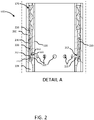
FIG. 2 illustrates a cross-section view of the shock strut assembly ofFIG. 1 , in accordance with various embodiments; -
FIG. 3 illustrates an exploded view of a rebound valve system, in accordance with various embodiments; -
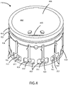
FIG. 4 illustrates a perspective view of a snubber, in accordance with various embodiments; -
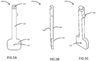
FIG. 5A illustrates a front view of a restrictor valve, in accordance with various embodiments; -
FIG. 5B illustrates a side view of a restrictor valve, in accordance with various embodiments; -
FIG. 5C illustrates a perspective view of a restrictor valve, in accordance with various embodiments; -
FIG. 6 illustrates a front view of a seal valve in accordance with various embodiments; -
FIG. 7 illustrates a snubber assembly in accordance with various embodiments; -
FIG. 8 illustrates a cross-sectional view along section line B-B fromFIG. 1 , in accordance with various embodiments; -
FIG. 9 illustrates a cross-sectional view along section line B-B fromFIG. 1 , in accordance with various embodiments; -
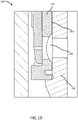
FIG. 10 illustrates a cross-sectional view of a portion of a rebound valve system, in accordance with various embodiments; -
FIG. 11 illustrates a side view of a portion of a shock strut assembly with a rebound valve system, in accordance with various embodiments; and -
FIG. 12 illustrates a cross-sectional view of a portion of a rebound valve system, in accordance with various embodiments. - The detailed description of exemplary embodiments herein makes reference to the accompanying drawings, which show exemplary embodiments by way of illustration. While these exemplary embodiments are described in sufficient detail to enable those skilled in the art to practice the disclosure, it should be understood that other embodiments may be realized and that logical changes and adaptations in design and construction may be made in accordance with this disclosure and the teachings herein without departing from the scope of the invention as defined by the claims. Thus, the detailed description herein is presented for purposes of illustration only and not of limitation.
- In various embodiments, a rebound valve system for a shock strut assembly is disclosed herein. The rebound valve system may be configured to meter oil to slow down a piston extension in the shock strut assembly, or the like. In this regard, the rebound valve system may be configured to dampen the piston extension. Typical rebound valve systems may include slip rings, which may be difficult to manufacture, and/or may cause issues with assembly of the shock strut assembly. The rebound valve system disclosed herein may include a plurality of restrictor valves disposed circumferentially about a piston and/or a snubber of the shock strut assembly. In various embodiments, the rebound valve system may further comprise a plurality of seal valves. In various embodiments, the plurality of restrictor valves and the plurality of seal valves may be configured to transition from a closed position, or partially closed position, to allow a free flow of oil to a rebound chamber from a hydraulic chamber of the shock strut assembly. In various embodiments, the plurality of restrictor valves may allow metered flow from the rebound chamber to the hydraulic chamber when in a closed position.
- Referring now to
FIG. 1 , ashock strut assembly 100 for use in a landing gear system, in accordance with various embodiments, is illustrated. Theshock strut assembly 100 may comprise astrut cylinder 110, astrut piston 120, ametering pin 140, anorifice support tube 150, and arebound valve system 160.Strut piston 120 may be operatively coupled to strutcylinder 110 as described herein.Strut cylinder 110 may be configured to receivestrut piston 120 in a manner that allows the two components to telescope together and absorb and/or dampen forces transmitted thereto. In various embodiments, a liquid, such as a hydraulic fluid and/or oil may be located withinstrut cylinder 110. A gas, such as nitrogen or air, may also be located withinstrut cylinder 110.Strut cylinder 110 andstrut piston 120 may, for example, be configured to seal such that fluid contained withinstrut cylinder 110 is prevented from leaking asstrut piston 120 translates relative to strutcylinder 110. Themetering pin 140 and theorifice support tube 150 may be positioned withinprimary chamber 130. Themetering pin 140 may translate withstrut piston 120. -
Shock strut assembly 100 may comprise a low pressure,primary chamber 130 in which oil and gas can mix. In this regard, a volume of gas (also referred to herein as a primary chamber gas volume) 131 and a volume of oil (also referred to herein as an oil volume) 133 may be contained withinprimary chamber 130. A portion ofprimary chamber 130 may contain the primarychamber gas volume 131 and may be referred to as aprimary gas chamber 132. Similarly, the portion ofprimary chamber 130 containing theoil volume 133 may be referred to herein as anoil chamber 134. Dashedline 135 represents the level ofoil volume 133, or the interface between theoil chamber 134 and theprimary gas chamber 132. Stated differently, theoil volume 133 may be located below dashedline 135 and primarychamber gas volume 131 may be located above dashedline 135. In this regard, the interface between theoil chamber 134 and theprimary gas chamber 132 may move relative toprimary chamber 130 depending on the position ofstrut piston 120 relative to strutcylinder 110. -
Shock strut assembly 100 may further compriserebound chamber 136. Therebound chamber 136 is disposed between thestrut cylinder 110 and an outer diameter surface of thestrut piston 120. Therebound chamber 136 expands when thestrut cylinder 110 is compressed, and therebound chamber 136 contracts when thestrut cylinder 110 extends. - In various embodiments, the
rebound valve system 160 is configured to allow free flow into therebound chamber 136. In various embodiments, therebound valve system 160 is configured to prevent or minimize cavitation. When thestrut piston 120 extends, therebound valve system 160 is configured to close and oil flow out of the rebound chamber is restricted, or metered, by therebound valve system 160. In various embodiments, therebound valve system 160 is configured to control the extend rate and snub thestrut piston 120 bottoming force at full extension. - Referring now to
FIG. 2 , detail A ofshock strut assembly 100 withrebound valve system 160 fromFIG. 1 , in accordance with various embodiments, is illustrated. In various embodiments, theshock strut assembly 100 further comprises anupper bearing assembly 170. Theupper bearing assembly 170 is disposed adjacent to therebound valve system 160. In various embodiments, therebound valve system 160 includes thestrut piston 120, asnubber 210, and a plurality ofrestrictor valves 220. In various embodiments, thesnubber 210 is disposed radially outward of thestrut piston 120, and the pluralityrestrictor valves 220 are disposed radially outward of thesnubber 210. In various embodiments, arebound valve system 160 may exclude asnubber 210, and the restrictor valves may be operably coupled directly to thestrut piston 120. In various embodiments, having thesnubber 210 may reduce manufacturing costs of thestrut piston 120 and/or simplify assembly of theshock strut assembly 100 fromFIG. 1 . - In various embodiments, the
strut piston 120 comprises a plurality ofradial apertures 122, and thesnubber 210 comprises a plurality ofradial apertures 212. In various embodiments, the plurality ofradial apertures 212 of thesnubber 210 are aligned radially and axially with the plurality ofradial apertures 122 of thestrut piston 120. In various embodiments, each radial aperture in the plurality ofradial apertures 212 of thesnubber 210 may be larger in diameter relative to a respective radial aperture in the plurality ofradial apertures 122 of the strut piston. In this regard, thesnubber 210 may include looser tolerances for the plurality ofradial apertures 212, reducing manufacturing costs and/or facilitating assembly of theshock strut assembly 100 fromFIG. 1 . - In various embodiments, each restrictor valve in the plurality of
restrictor valves 220 comprises an orifice. For example, arestrictor valve 230 in the plurality ofrestrictor valves 220 comprises anorifice 232. In various embodiments, theorifice 232 may be configured to meter flow fromrebound chamber 136 during strut extension. - The
rebound chamber 136 and theprimary chamber 132 are in fluid communication through therebound valve system 160. For example, when the plurality ofrestrictor valves 220 are closed during strut extension, oil disposed in therebound chamber 136 may flow outrebound chamber 136 through an orifice of a respective restrictor valve, a respective aperture of thesnubber 210, and a respective aperture of thestrut piston 120. For example, oil may flow through theorifice 232 of therestrictor valve 230, through a firstradial aperture 213 in the plurality ofradial apertures 212 of the snubber, and through a firstradial aperture 123 in the plurality ofradial apertures 122 of thestrut piston 120 to theprimary chamber 132. - In various embodiments, the plurality of
restrictor valves 220 are operably coupled to thesnubber 210. Although illustrated as being operably coupled to thesnubber 210, the plurality ofrestrictor valves 220 are not limited in this regard. For example, the plurality ofrestrictor valves 220 may be operably coupled directly to thestrut piston 120 in accordance with various embodiments. In various embodiments, the plurality ofrestrictor valves 220 are pivotably coupled to thesnubber 210 as described further herein. Although illustrated as being pivotably coupled to thesnubber 210, the plurality of restrictor valves are not limited in this regard. For example, the plurality ofrestrictor valves 220 may be a loose component disposed between thesnubber 210 and thestrut cylinder 110. In this regard, the plurality of restrictor valves may translate open and closed based on a pressure differential during extension or compression of thestrut cylinder 110. In various embodiments, having the plurality ofrestrictor valves 220 pivotably coupled to thesnubber 210 may provide a more consistent opening and closing motion of the plurality of restrictor valves and provide for ease of assembly of theshock strut assembly 100 inFIG. 1 . - In various embodiments,
snubber 210 is clocked to thestrut piston 120 in order to maintain the radial flow paths through the plurality ofradial apertures 122 and the plurality ofradial apertures 212. In various embodiments, this clocking may be achieved by any known method known in the art. - Referring now to
FIG. 3 , an exploded view of a portion of ashock strut assembly 100 with arebound valve system 160, in accordance with various embodiments, is illustrated. In various embodiments, therebound valve system 160 may further comprise a plurality ofseal valves 240. Each seal valve in the plurality ofseal valves 240 may be similar to a restrictor valve in the plurality ofrestrictor valves 220, with the exception of the orifice (e.g.,orifice 232 of restrictor valve 230) and a keying feature, as described further herein. In various embodiments, by havingrestrictor valves 220 and sealvalves 240, the orifices of the restrictor valves may be sized larger than if all of the valves were restrictor valves. In this regard, by havingrestrictor valves 220 and sealvalves 240 instead of only restrictor valves, the orifice of therestrictor valves 220 may be more manufacturable, in various embodiments. However, although described herein withrestrictor valves 220 and sealvalves 240, a rebound valve system with onlyrestrictor valves 220 is within the scope of this disclosure, and would provide fewer types of components to manufacture, in accordance with various embodiments. - In various embodiments, the
rebound valve system 160 may further comprise a retainingring 250 and thesnubber 210 comprises acircumferential receptacle 214. In various embodiments, the retainingring 250 is disposed in thecircumferential receptacle 214 of the snubber, and each restrictor valve in the plurality ofrestrictor valves 220 and each seal valve in the plurality ofseal valves 240 may be pivotably coupled to the retainingring 250. In this regard, each restrictor valve in the plurality ofrestrictor valves 220 and each seal valve in the plurality ofseal valves 240 is configured to pivot about a centerline of the retainingring 250. In various embodiments, by pivotably coupling therestrictor valves 220 and theseal valves 240, a significantly lower force of oil may open thevalves - In various embodiments, the
rebound valve system 160 further comprises acylindrical seal 260. Thecylindrical seal 260 is configured to sealrebound chamber 136 fromprimary chamber 132 inFIG. 1 , in accordance with various embodiments. - Referring now to
FIG. 4 , a perspective view of asnubber 210 for use in the rebound valve system ofFIGs. 1-3 is illustrated, in accordance with various embodiments. Thesnubber 210 comprises asnubber body 402 and a plurality ofvalve receptacles 410. In various embodiments, thesnubber body 402 is annular in shape having anouter diameter surface 404 and aninner diameter surface 406. In various embodiments, the plurality ofvalve receptacles 410 are disposed in theouter diameter surface 404 of thesnubber body 402. In various embodiments, each valve receptacle in the plurality ofvalve receptacles 410 comprises a recess disposed in theouter diameter surface 404 of thesnubber body 402. - In various embodiments, each valve receptacle in the plurality of
valve receptacles 410 may be a complimentary shape of a respective restrictor valve in the plurality ofrestrictor valves 220 or seal valve in the plurality ofseal valves 240 fromFIG. 3 . In this regard, a snubber assembly may include the seal valves and restrictor valves disposed in the plurality ofvalve receptacles 410. - In various embodiments, the plurality of
valve receptacles 410 may include a plurality ofrestrictor valve receptacles 412 and a plurality ofseal valve receptacles 414. In various embodiments, each restrictor valve receptacle in the plurality ofrestrictor valve receptacles 412 may be configured to receive a respective restrictor valve in the plurality ofrestrictor valves 220 fromFIGs. 2-3 . Similarly, each seal valve receptacle in the plurality ofseal valve receptacles 414 may be configured to receive a respective seal valve in the plurality ofseal valves 240 fromFIG. 3 . In this regard, each valve receptacle in the plurality ofvalve receptacles 410 may contain a keying feature, such as a specifically oriented recess, to ensure a respective seal valve or a respective restrictor valve is appropriately disposed in the respective valve receptacle. In various embodiments, each receptacle in the plurality ofvalve receptacles 410 have a flat bottom substantially perpendicular to a radius of thesnubber body 402. In various embodiments, the plurality of valve receptacles may be sized and configured not to restrict free flow into therebound chamber 136 fromFIG. 2 . - In various embodiments the
snubber 210 further comprises a retaininggroove 408 disposed in theouter diameter surface 406 of thesnubber body 402. The retaininggroove 408 may extend circumferentially around thesnubber body 402. The retaininggroove 408 may be configured to receive a retaining band as described further herein. - In various embodiments, the
snubber 210 further comprises afirst seal groove 403 and asecond seal groove 405. Thefirst seal groove 403 is disposed on theouter diameter surface 406. Thesecond seal groove 405 is disposed on theinner diameter surface 404 of thesnubber body 402. Thefirst seal groove 403 extends circumferentially around theouter diameter surface 406 of the snubber body. Similarly, thesecond seal groove 405 extends circumferentially around theinner diameter surface 404 of thesnubber body 402. - In various embodiments, the
snubber 210 further comprises the plurality ofradial apertures 212. Each radial aperture in the plurality of radial apertures is disposed radially through thesnubber body 402 and disposed in a respective blade pocket of a respective valve receptacle in the plurality ofvalve receptacles 410. In this regard, the plurality ofradial apertures 212 are configured to interface with a respective valve in the plurality of valves as disclosed further herein. - Referring now to
FIGs. 5A-5C , a front view (FIG. 5A ), a side view (FIG. 5B ), and a perspective view (FIG. 5C ) of arestrictor valve 230 for use in arebound valve system 160 ofFIGs. 1-3 is illustrated, in accordance with various embodiments. In various embodiments, therestrictor valve 230 includes agrip 510, ashaft 520, and ablade 530. In various embodiments, thegrip 510 may provide a pivot point to open and close therestrictor valve 230. In various embodiments, thegrip 510 may comprise a hook. Although illustrated as comprising a hook, any grip arrangement is within the scope of this disclosure, such as a tee head, a spherical joint, or the like. - In various embodiments, the
shaft 520 extends from thegrip 510 to theblade 530. In various embodiments, theshaft 520 may help maintain a beneficial paddle orientation in a valve open position. The length of theshaft 520 may vary based on the application. In various embodiments, as the shaft length increases, the angle traveled between a valve open position and a valve closed position may decrease. In various embodiments, as the travel angle decreases, a sensitivity of therestrictor valve 230 to pressure differentials and flow will increase and response time will decrease. - In various embodiments, the
blade 530 is configured to react to differential pressures resulting from a force from the flow into or out of therebound chamber 136 fromFIGs. 1 and2 . In various embodiments, theblade 530 includes aflat surface 532 configured to interface with a mating surface of a respective restrictor valve receptacle in the plurality ofrestrictor valve receptacles 412 fromFIG. 4 . In this regard, theblade 530 is configured to partially cover an aperture disposed through the snubber (e.g.,radial aperture 213 inFIG. 2 ). - In various embodiments, the
shaft 520 includes afirst side surface 522 and asecond side surface 524. In various embodiments, theflat surface 532 of theblade 530 protrudes outward slightly from thefirst side surface 522. In this regard, theflat surface 532 of theblade 530 is configured to contact the recess of a respective valve receptacle prior to any other part of therestrictor valve 230. In various embodiments, thesecond side surface 524 is disposed opposite thefirst side surface 522 of theshaft 520. Althoughshaft 520 is illustrated as being cubic in shape, theshaft 520 is not limited in this regard and may comprise other shapes, such as cylindrical, or the like. - In various embodiments, the
blade 530 of therestrictor valve 230 includes theorifice 232 disposed therethrough. Theorifice 232 is sized and configured based on a desired amount of metering desired during a strut extension of a strut assembly (e.g.,shock strut assembly 100 fromFIG. 1 ). - In various embodiments, the
restrictor valve 230 includes a keying feature, such as aprotrusion 540. Although illustrated as aprotrusion 540, any keying feature known in the art may be utilized. In various embodiments, the keying feature (e.g., protrusion 540) may extend outward from a third side surface 526 of theshaft 520. The third side surface 526 may extend from thefirst side surface 522 to thesecond side surface 524. - Referring now to
FIG. 6 , a front view of aseal valve 600 of the plurality ofseal valves 240 fromFIG. 3 for use in therebound valve system 160 fromFIGs. 1-3 is illustrated, in accordance with various embodiments. Theseal valve 600 includes agrip 610, ashaft 620 and ablade 630. Thegrip 610 is in accordance with thegrip 510 of therestrictor valve 230 discussed above. Similarly, theshaft 620 is in accordance with theshaft 520 of the restrictor valve 500 discussed above. Theblade 630 is in accordance with theblade 530 of the restrictor valve 500 discussed above, with the exception of theorifice 232 of restrictor valve 500. In various embodiments,blade 630 does not include an orifice. In this regard, during extension of astrut cylinder 110 fromFIG. 1 , theblade 630 is configured to at least partially seal a respective radial aperture of the snubber and/or the strut piston of the strut assembly. In various embodiments, theseal valve 600 includes a keying feature that is different from the keying feature (e.g., protrusion 540) of restrictor valve 500 fromFIG. 5 . For example, theseal valve 600 may include aprotrusion 640 on aside surface 622 of theshaft 620. Theside surface 622 may be a different side surface ofshaft 620 than third side surface 526 of restrictor valve 500 fromFIG. 5 . In this regard, mis-assembly of a restrictor valve 500 fromFIG 5 and aseal valve 600 may be prevented. - Referring now to
FIG. 7 , a perspective view of asnubber assembly 700 for use in arebound valve system 160 fromFIGs. 1-2 is illustrated, in accordance with various embodiments. Thesnubber assembly 700 comprises the snubber 210 (as illustrated inFIG. 4 ) and a plurality ofrestrictor valves 220. In various embodiments, each restrictor valve in the plurality ofrestrictor valves 220 are in accordance with the restrictor valve 230 (as illustrated inFIG. 5 ). - In various embodiments, each restrictor valve in the plurality of
restrictor valves 220 are moveably coupled to thesnubber 210 by any method known in the art. Although illustrated as being pivotably coupled to thesnubber 210, the present disclosure is not limited in this regard. For example, the plurality ofrestrictor valves 220 may be slidingly coupled to thesnubber 210, or the like. - In various embodiments, the
snubber assembly 700 further comprises a retainingring 250. The retainingring 250 may comprise an annular shaped band, or the like. The retaining band may be disposed in the retaininggroove 408 of thesnubber 210 fromFIG. 4 . In various embodiments, thesnubber 210 further comprises ananti-rotation pocket 409 disposed in theouter diameter surface 406 of thesnubber body 402. Theanti-rotation pocket 409 is configured to receive a first end and a second end of the retainingring 250. In this regard, theanti-rotation pocket 409 is configured to prevent rotation of retainingring 250 during operation of thesnubber assembly 700. - Referring now to
FIG. 8 , a cross-sectional view ofshock strut assembly 100 along section line B-B fromFIG. 1 during strut extension is illustrated, in accordance with various embodiments. In various embodiments, therebound valve system 160 is configured to dampen the strut extension. In this regard, oil may flow from therebound chamber 136 back through anorifice 232 of a respectiverestrictor valve 230 in the plurality ofrestrictor valves 220 through a respective radial aperture of the plurality ofradial apertures 212 of thesnubber 210 and a respective radial aperture of the plurality ofradial apertures 122 of thestrut piston 120. In various embodiments, the metered oil flow during strut extension may dampen the strut extension. The amount of oil that is metered may be a design choice and vary based on a desired damping level and desired velocity of the strut extension. - In various embodiments, each restrictor valve in the plurality of
restrictor valves 220 may be equidistant, measured in a circumferential direction, from an adjacent restrictor valve in the plurality ofrestrictor valves 220. For example, if there are four restrictor valves, each restrictor valve may be approximately 90 degrees from an adjacent restrictor valve in the plurality ofrestrictor valves 220. In this regard, the metered flow during strut extension may be evenly distributed circumferentially about theshock strut assembly 100. - In various embodiments, by having a plurality of
restrictor valves 220, if one of the restrictor valves is clogged from debris, or the like, the remaining restrictor valves in the plurality ofrestrictor valves 220 may still function as intended. In this regard, therebound valve system 160 of theshock strut assembly 100 may be more robust than typical rebound valve systems. - In various embodiments, during the strut extension, the plurality of
seal valves 240 may seal a respective radial aperture in the plurality ofradial apertures 212 of thesnubber 210. In this regard, the sizing of theorifice 232 of therestrictor valve 230 may be more manageable than if all valves in the plurality of valves included orifices. Although illustrated as including four restrictor valves and eight seal valves, the present disclosure is not limited in this regard. In other words, there would not be a constraint on the total number of apertures. In various embodiments, all of the valves may berestrictor valves 230, or a ratio of seal valves to restrictor valves may be increased or decreased and be within the scope of this disclosure. - Referring now to
FIG. 9 , a cross-sectional view ofshock strut assembly 100 along section line B-B fromFIG. 1 during strut compression is illustrated, in accordance with various embodiments. During strut compression, a free flow of oil into therebound chamber 136 fromFIG. 2 may be desired. In this regard, oil may flow from theprimary chamber 132 through the plurality ofradial apertures 122 of thestrut piston 120 and the plurality ofradial apertures 212 of thesnubber 210, lightly pivot the plurality ofvalves rebound chamber 136 fromFIG. 2 . - Referring now to
FIG. 10 , a cross-section view of a portion of arebound valve system 160 is illustrated, in accordance with various embodiments. In various embodiments, thesnubber 210 may further comprise a flow ingroove 1002 disposed in aninner diameter surface 1004 of thesnubber 210. The flow ingroove 1002 may extend circumferentially around theinner diameter surface 1004. In this regard, a different number of radial apertures in thestrut piston 120 and thesnubber 210 may be utilized as long as a minimum flow area is maintained. In various embodiments, thegroove 1002 may eliminate a snubber from having to be clocked to a certain angle relative to strutpiston 120 during assembly. However, thegroove 1002 may add some additional flow restriction. - Referring now to
Fig. 11 , a side view of a portion of a shock strut assembly having arebound valve system 160 in accordance with various embodiments is illustrated. In various embodiments, therebound valve system 160 may further comprise aramp split ring 1102 disposed axially adjacent to thecylindrical seal 260. - In various embodiments, the ramp split ring may be configured to vent and/or purge gas that becomes trapped in the rebound chamber (e.g., rebound
chamber 136 fromFIG. 1 ). In various embodiments, theramp split ring 1102 includes agap 1104. In various embodiments, thegap 1104 may allow gas to be purged from the rebound chamber (e.g., reboundchamber 136 fromFIG. 1 ) as long as all the gas migrates along the annular space to thegap 1104. - In various embodiments, the
cylindrical seal 260 and theramp split ring 1102 may be clocked to thesnubber 210 to align agap 1106 of thecylindrical seal 260 and thegap 1106 of theramp split ring 1102. In this regard, the gas may eventually travel to the location of thegap 1104, in accordance with various embodiments. In various embodiments, theramp split ring 1102 may be configured to optimize effectiveness, gaps between thestrut cylinder 110 fromFIG. 1 and thesnubber 210 may be minimized. In various embodiments, theramp split ring 1102 acts as a guide ring. In various embodiments, theramp split ring 1102 is further illustrated in a cross-sectional view inFIG. 12 . - Benefits, other advantages, and solutions to problems have been described herein with regard to specific embodiments. Furthermore, the connecting lines shown in the various figures contained herein are intended to represent exemplary functional relationships and/or physical couplings between the various elements. It should be noted that many alternative or additional functional relationships or physical connections may be present in a practical system. However, the benefits, advantages, solutions to problems, and any elements that may cause any benefit, advantage, or solution to occur or become more pronounced are not to be construed as critical, required, or essential features or elements of the disclosure.
- The scope of the disclosure is accordingly to be limited by nothing other than the appended claims, in which reference to an element in the singular is not intended to mean "one and only one" unless explicitly so stated, but rather "one or more." It is to be understood that unless specifically stated otherwise, references to "a," "an," and/or "the" may include one or more than one and that reference to an item in the singular may also include the item in the plural. All ranges and ratio limits disclosed herein may be combined.
- Moreover, where a phrase similar to "at least one of A, B, and C" is used in the claims, it is intended that the phrase be interpreted to mean that A alone may be present in an embodiment, B alone may be present in an embodiment, C alone may be present in an embodiment, or that any combination of the elements A, B and C may be present in a single embodiment; for example, A and B, A and C, B and C, or A and B and C.
- The steps recited in any of the method or process descriptions may be executed in any order and are not necessarily limited to the order presented. Furthermore, any reference to singular includes plural embodiments, and any reference to more than one component or step may include a singular embodiment or step. Elements and steps in the figures are illustrated for simplicity and clarity and have not necessarily been rendered according to any particular sequence. For example, steps that may be performed concurrently or in different order are illustrated in the figures to help to improve understanding of embodiments of the present disclosure.
- Any reference to attached, fixed, connected or the like may include permanent, removable, temporary, partial, full and/or any other possible attachment option. Additionally, any reference to without contact (or similar phrases) may also include reduced contact or minimal contact. Surface shading lines may be used throughout the figures to denote different parts or areas but not necessarily to denote the same or different materials. In some cases, reference coordinates may be specific to each figure.
- Systems, methods and apparatus are provided herein. In the detailed description herein, references to "one embodiment," "an embodiment," "various embodiments," etc., indicate that the embodiment described may include a particular feature, structure, or characteristic, but every embodiment may not necessarily include the particular feature, structure, or characteristic. Moreover, such phrases are not necessarily referring to the same embodiment. Further, when a particular feature, structure, or characteristic is described in connection with an embodiment, it is submitted that it is within the knowledge of one skilled in the art to affect such feature, structure, or characteristic in connection with other embodiments whether or not explicitly described. After reading the description, it will be apparent to one skilled in the relevant art(s) how to implement the disclosure in alternative embodiments.
Claims (15)
- A snubber assembly, comprising:a snubber (210) having a snubber body (402) with an inner diameter surface and an outer diameter surface, the snubber including a plurality of valve receptacles (410) disposed in the outer diameter surface, the snubber including a plurality of radial apertures (212) disposed through the snubber body, each radial aperture in the plurality of radial apertures disposed in a respective valve receptacle in the plurality of valve receptacles; anda plurality of restrictor valves (220), each restrictor valve in the plurality of restrictor valves disposed in a respective valve receptacle in the plurality of valve receptacles, each restrictor valve in the plurality of restrictor valves including an orifice disposed through a blade.
- The snubber assembly of claim 1, further comprising a retaining ring (250), wherein the retaining ring couples the plurality of restrictor valves to the snubber body.
- The snubber assembly of claim 2, wherein the plurality of restrictor valves are configured to pivot about the retaining ring.
- The snubber assembly of claim 1, 2 or 3, further comprising a plurality of seal valves (240) disposed in a portion of the plurality of valve receptacles, wherein the plurality of restrictor valves are disposed in a remaining portion of the plurality of valve receptacles, and optionally wherein the plurality of seal valves include a first keying feature and the plurality of restrictor valves include a second keying feature to prevent mis-assembly.
- The snubber assembly of any preceding claim, wherein each restrictor valve in the plurality of restrictor valves includes a grip (510), the blade (530), and a shaft (520) extending from the grip to the blade, and optionally wherein the orifice (232) is disposed through the blade.
- A rebound valve system, comprising:a strut piston (120) defining an oil chamber, the strut piston including a plurality of radial apertures disposed radially through the strut piston;a strut cylinder (110) configured to receive the strut piston, a rebound chamber (136) defined between the strut piston and the strut cylinder; anda plurality of restrictor valves (220) disposed circumferentially around the strut piston, each restrictor valve in the plurality of restrictor valves configured to open during a compression of the strut piston relative to the strut cylinder, and each restrictor valve configured to at least partially close during an extension of the strut piston.
- The rebound valve system of claim 6, wherein each restrictor valve in the plurality of restrictor valves includes an orifice disposed through a blade.
- The rebound valve system of claim 7, wherein a fluid is configured to flow from the rebound chamber through the orifice and a respective radial aperture in the plurality of radial apertures into the primary chamber during the extension of the strut piston, and optionally wherein a flow of fluid is configured to pivot the plurality of restrictor valves about a pivot axis to open the plurality of restrictor valves during the compression of the strut piston.
- The rebound valve system of claim 6, 7 or 8, further comprises a plurality of seal valves (240), wherein each seal valve in the plurality of seal valves is configured to seal a respective radial aperture in the plurality of radial apertures during the extension of the strut piston.
- The rebound valve system of any claims 6 to 9, further comprising a snubber (210) disposed between the strut cylinder and the strut piston, and optionally wherein the plurality of restrictor valves are disposed between the snubber and the strut cylinder.
- A shock strut assembly, comprising:a strut cylinder (110);a strut piston (120), the strut cylinder configured to receive the strut piston, the strut piston defining an oil chamber (134); anda snubber assembly disposed between the strut cylinder and the strut piston, the snubber assembly comprising:a snubber (210) having a plurality of valve receptacles disposed in an outer diameter surface of the snubber; anda plurality of restrictor valves (220), each restrictor valve disposed in a respective valve receptacle in the plurality of valve receptacles, each restrictor valve in the plurality of restrictor valves configured to open during a compression of the strut piston relative to the strut cylinder, and each restrictor valve configured to at least partially close during an extension of the strut piston.
- The shock strut assembly of claim 11, wherein each restrictor valve includes a grip (510), a blade (530), and a shaft (520) extending from the grip to the blade, and each restrictor valve is configured to pivot about the grip.
- The shock strut assembly of claim 11 or 12, further comprising a plurality of seal valves (240) disposed in a portion of the plurality of valve receptacles, wherein the plurality of restrictor valves are disposed in a remaining portion of the plurality of valve receptacles.
- The shock strut assembly of claim 11, 12 or 13, further comprising a retaining ring (250), wherein the plurality of restrictor valves are coupled to the retaining ring, and wherein the retaining ring is coupled to the snubber.
- The shock strut assembly of any claims 11 to 14, wherein the primary chamber is in fluid communication with a rebound chamber through the plurality of restrictor valves, the rebound chamber defined between the strut piston and the strut cylinder, and/or wherein a flow of fluid is configured to pivot the plurality of restrictor valves about a pivot axis to open the plurality of restrictor valves during the compression of the strut piston.
Applications Claiming Priority (1)
| Application Number | Priority Date | Filing Date | Title |
|---|---|---|---|
| US17/033,081 US11608163B2 (en) | 2020-09-25 | 2020-09-25 | Rebound valve systems and methods |
Publications (1)
| Publication Number | Publication Date |
|---|---|
| EP3978779A1 true EP3978779A1 (en) | 2022-04-06 |
Family
ID=77998745
Family Applications (1)
| Application Number | Title | Priority Date | Filing Date |
|---|---|---|---|
| EP21199161.7A Pending EP3978779A1 (en) | 2020-09-25 | 2021-09-27 | Rebound valve systems and methods |
Country Status (4)
| Country | Link |
|---|---|
| US (1) | US11608163B2 (en) |
| EP (1) | EP3978779A1 (en) |
| BR (1) | BR102021017938A2 (en) |
| CA (1) | CA3129811A1 (en) |
Citations (3)
| Publication number | Priority date | Publication date | Assignee | Title |
|---|---|---|---|---|
| EP0299588A2 (en) * | 1985-08-19 | 1989-01-18 | Pneumo Abex Corporation | Landing gear mechanism for use on rough runways |
| FR2687123A1 (en) * | 1992-02-11 | 1993-08-13 | Eram | Retractable landing gear of an aircraft, especially for a helicopter |
| US20150129381A1 (en) * | 2013-11-13 | 2015-05-14 | Goodrich Corporation | Cam-operated bi-directional shock absorber damper |
Family Cites Families (5)
| Publication number | Priority date | Publication date | Assignee | Title |
|---|---|---|---|---|
| FR993888A (en) * | 1944-11-06 | 1951-11-08 | Olaer Patent Co | Landing strut for airplanes |
| FR948387A (en) * | 1947-06-05 | 1949-07-29 | Siam | Improvements to liquid compression dampers |
| FR2530763B1 (en) * | 1982-07-22 | 1987-01-23 | Messier Hispano Sa | RETRACTABLE SHOCK ABSORBER |
| US4552324A (en) | 1983-05-31 | 1985-11-12 | Pneumo Corporation | Landing gear mechanism for use on rough runways |
| US4787486A (en) | 1986-06-19 | 1988-11-29 | Pneumo Abex Corporation | Landing gear mechanism including controlled instroke and rebound damping and stroke overload protection |
-
2020
- 2020-09-25 US US17/033,081 patent/US11608163B2/en active Active
-
2021
- 2021-09-02 CA CA3129811A patent/CA3129811A1/en active Pending
- 2021-09-10 BR BR102021017938-4A patent/BR102021017938A2/en not_active Application Discontinuation
- 2021-09-27 EP EP21199161.7A patent/EP3978779A1/en active Pending
Patent Citations (3)
| Publication number | Priority date | Publication date | Assignee | Title |
|---|---|---|---|---|
| EP0299588A2 (en) * | 1985-08-19 | 1989-01-18 | Pneumo Abex Corporation | Landing gear mechanism for use on rough runways |
| FR2687123A1 (en) * | 1992-02-11 | 1993-08-13 | Eram | Retractable landing gear of an aircraft, especially for a helicopter |
| US20150129381A1 (en) * | 2013-11-13 | 2015-05-14 | Goodrich Corporation | Cam-operated bi-directional shock absorber damper |
Also Published As
| Publication number | Publication date |
|---|---|
| BR102021017938A2 (en) | 2022-04-26 |
| US20220097833A1 (en) | 2022-03-31 |
| US11608163B2 (en) | 2023-03-21 |
| CA3129811A1 (en) | 2022-03-25 |
Similar Documents
| Publication | Publication Date | Title |
|---|---|---|
| US7216747B2 (en) | Amplitude controlled orifice valving | |
| US7926632B2 (en) | Shock absorber having a continuously variable valve with base line valving | |
| US7950506B2 (en) | Semi third tube design | |
| US2379388A (en) | Liquid damped telescopic shock absorber | |
| US4076276A (en) | Base valve for independent wheel suspension strut | |
| EP3739234B1 (en) | A damper assembly and a piston for a damper assembly | |
| US11204075B2 (en) | Free-floating washer for rebound damping | |
| US20100193308A1 (en) | Triple tube shock absorber having a shortened intermediate tube | |
| EP1710102B1 (en) | Adjustable shock absorber | |
| US4561641A (en) | Off-highway vehicle ride strut and method | |
| US4284255A (en) | Shock absorbers and shock absorber struts, notably for aerodyne landing gear | |
| US4787486A (en) | Landing gear mechanism including controlled instroke and rebound damping and stroke overload protection | |
| EP3345828B1 (en) | Two stage strut allowing low initial compression load | |
| EP3428063B1 (en) | Hydraulic shimmy damper | |
| US12372133B2 (en) | Shock absorber | |
| US10577088B2 (en) | Aircraft landing gear shock absorbing strut | |
| US11608163B2 (en) | Rebound valve systems and methods | |
| US12552522B2 (en) | Shock strut variable-area metering unit | |
| US20230279921A1 (en) | Hydraulic compression stop with closable windows | |
| US20240409207A1 (en) | Energy absorption system for landing gear | |
| CA1290357C (en) | Rapidly opening peak-clipping valve for a hydropneumatic suspension for a heavy vehicle | |
| US12384530B2 (en) | Self-sustaining shimmy damper system for landing gear shock strut assemblies | |
| EP4474673A1 (en) | Energy absorption system for landing gear | |
| US4105194A (en) | Pump mechanism for a combined self-leveling shock absorber and fluid spring unit | |
| EP4198334A1 (en) | Self-sustaining shimmy damper system for landing gear shock strut assemblies |
Legal Events
| Date | Code | Title | Description |
|---|---|---|---|
| PUAI | Public reference made under article 153(3) epc to a published international application that has entered the european phase |
Free format text: ORIGINAL CODE: 0009012 |
|
| STAA | Information on the status of an ep patent application or granted ep patent |
Free format text: STATUS: THE APPLICATION HAS BEEN PUBLISHED |
|
| AK | Designated contracting states |
Kind code of ref document: A1 Designated state(s): AL AT BE BG CH CY CZ DE DK EE ES FI FR GB GR HR HU IE IS IT LI LT LU LV MC MK MT NL NO PL PT RO RS SE SI SK SM TR |
|
| STAA | Information on the status of an ep patent application or granted ep patent |
Free format text: STATUS: REQUEST FOR EXAMINATION WAS MADE |
|
| 17P | Request for examination filed |
Effective date: 20221004 |
|
| RBV | Designated contracting states (corrected) |
Designated state(s): AL AT BE BG CH CY CZ DE DK EE ES FI FR GB GR HR HU IE IS IT LI LT LU LV MC MK MT NL NO PL PT RO RS SE SI SK SM TR |
|
| P01 | Opt-out of the competence of the unified patent court (upc) registered |
Effective date: 20230922 |