EP3978771A1 - Automatic assembly apparatus and automatic assembly method for fixed type constant velocity universal joint - Google Patents
Automatic assembly apparatus and automatic assembly method for fixed type constant velocity universal joint Download PDFInfo
- Publication number
- EP3978771A1 EP3978771A1 EP21194802.1A EP21194802A EP3978771A1 EP 3978771 A1 EP3978771 A1 EP 3978771A1 EP 21194802 A EP21194802 A EP 21194802A EP 3978771 A1 EP3978771 A1 EP 3978771A1
- Authority
- EP
- European Patent Office
- Prior art keywords
- joint member
- cage
- cassette
- outer joint
- automatic assembly
- Prior art date
- Legal status (The legal status is an assumption and is not a legal conclusion. Google has not performed a legal analysis and makes no representation as to the accuracy of the status listed.)
- Pending
Links
- 238000000034 method Methods 0.000 title claims description 15
- 230000002093 peripheral effect Effects 0.000 claims abstract description 52
- 230000000717 retained effect Effects 0.000 claims abstract description 15
- 238000003780 insertion Methods 0.000 description 11
- 230000037431 insertion Effects 0.000 description 11
- 230000001105 regulatory effect Effects 0.000 description 6
- 238000010586 diagram Methods 0.000 description 3
- 230000001174 ascending effect Effects 0.000 description 2
- TVEXGJYMHHTVKP-UHFFFAOYSA-N 6-oxabicyclo[3.2.1]oct-3-en-7-one Chemical compound C1C2C(=O)OC1C=CC2 TVEXGJYMHHTVKP-UHFFFAOYSA-N 0.000 description 1
- 241000276425 Xiphophorus maculatus Species 0.000 description 1
- 230000000694 effects Effects 0.000 description 1
- 238000007689 inspection Methods 0.000 description 1
Images



Classifications
-
- F—MECHANICAL ENGINEERING; LIGHTING; HEATING; WEAPONS; BLASTING
- F16—ENGINEERING ELEMENTS AND UNITS; GENERAL MEASURES FOR PRODUCING AND MAINTAINING EFFECTIVE FUNCTIONING OF MACHINES OR INSTALLATIONS; THERMAL INSULATION IN GENERAL
- F16D—COUPLINGS FOR TRANSMITTING ROTATION; CLUTCHES; BRAKES
- F16D3/00—Yielding couplings, i.e. with means permitting movement between the connected parts during the drive
- F16D3/16—Universal joints in which flexibility is produced by means of pivots or sliding or rolling connecting parts
- F16D3/20—Universal joints in which flexibility is produced by means of pivots or sliding or rolling connecting parts one coupling part entering a sleeve of the other coupling part and connected thereto by sliding or rolling members
- F16D3/22—Universal joints in which flexibility is produced by means of pivots or sliding or rolling connecting parts one coupling part entering a sleeve of the other coupling part and connected thereto by sliding or rolling members the rolling members being balls, rollers, or the like, guided in grooves or sockets in both coupling parts
- F16D3/223—Universal joints in which flexibility is produced by means of pivots or sliding or rolling connecting parts one coupling part entering a sleeve of the other coupling part and connected thereto by sliding or rolling members the rolling members being balls, rollers, or the like, guided in grooves or sockets in both coupling parts the rolling members being guided in grooves in both coupling parts
-
- F—MECHANICAL ENGINEERING; LIGHTING; HEATING; WEAPONS; BLASTING
- F16—ENGINEERING ELEMENTS AND UNITS; GENERAL MEASURES FOR PRODUCING AND MAINTAINING EFFECTIVE FUNCTIONING OF MACHINES OR INSTALLATIONS; THERMAL INSULATION IN GENERAL
- F16D—COUPLINGS FOR TRANSMITTING ROTATION; CLUTCHES; BRAKES
- F16D2300/00—Special features for couplings or clutches
- F16D2300/12—Mounting or assembling
Definitions
- the present invention relates to an automatic assembly apparatus and an automatic assembly method for a fixed type constant velocity universal joint.
- a fixed type constant velocity universal joint As a constant velocity universal joint which transmits torque at a constant velocity while tolerating angle change between two axes, a fixed type constant velocity universal joint as illustrated in Fig. 6 is well-known.
- This fixed type constant velocity universal joint has: an inner joint member 2 as an inside joint member, with a plurality of track grooves 1 formed on an outer periphery thereof; an outer joint member 7 as an outside joint member, with a plurality of track grooves 6 formed on an inner periphery thereof; a plurality of balls 8 which engage with both track grooves 1 and 6 to transmit torque between the inner joint member 2 and the outer joint member 7; and a cage 4 having a plurality of pockets 3 which house the balls 8 one by one and fitting an outer peripheral spherical surface of the inner joint member 2 and an inner peripheral spherical surface of the outer joint member 7.
- An end portion of a shaft 10 is inserted into a shaft hole 9 formed in the inner joint member 2, and the shaft 10 and the shaft hole 9 are s
- Patent Literature 1 a method in which the above-mentioned fixed type constant velocity universal joint is automatically assembled is shown. Specifically, first, a temporary assembly of the cage 4 and the inner joint member 2 (hereinafter, referred to as a "cassette 5") is conveyed to an automatic assembly apparatus and positioning of the pockets 3 of the cage 4 and the track grooves 1 of the inner joint member 2 in a circumferential direction is conducted. Then, one of the balls 8 (a reference ball 8a) is assembled into one of the pockets 3 of the cage 4. This reference ball 8a is engaged with the track groove 1 of the inner joint member 2 and the pocket 3 of the cage 4, thereby conducting the positioning of both (rotation locking). Thereafter, as illustrated in Fig.
- the cassette 5 is rotated by 90° with a rotational axis in the horizontal direction as a center, whereby as illustrated in Fig. 10 , the cassette 5 is housed in the inner periphery of the outer joint member 7. Thereafter, the cassette 5 is inclined, each of the pockets 3 is exposed outside the outer joint member 7 one by one, and each of the balls 8 is assembled into each of the pockets 3.
- Patent Literature 1 JP-B-6-15885
- an object of the present invention is to prevent positional deviation of the cage and the inner joint member and to prevent failure of assembling balls without requiring the reference ball upon automatically assembling the cassette (the cage and the inner joint member) of the fixed type constant velocity universal joint to the outer joint member.
- the present invention provides a method for automatically assembling a fixed type constant velocity universal joint, which includes: an inner joint member which has a plurality of track grooves and a shaft hole for attaching a shaft; an outer joint member which has a plurality of track grooves; a plurality of balls which engage with the track grooves of the inner joint member and the track grooves of the outer joint member to transmit torque; and a cage having a plurality of pockets which house the plurality of balls and fitting an outer peripheral spherical surface of the inner joint member and an inner peripheral spherical surface of the outer joint member.
- This method includes the successive steps of: conveying, into an automatic assembly apparatus, a cassette being configured by fitting an inner peripheral spherical surface of the cage and the outer peripheral spherical surface of the inner joint member; retaining the cassette by fitting a shaft part being provided for a cassette cage part of the automatic assembly apparatus into the shaft hole of the inner joint member and by gripping the inner peripheral surface of the cage by a gripping means being provided for the cassette cage part; inserting the cassette into an inner periphery of the outer joint member in a state in which an axis line of the cassette being retained by the cassette cage part and an axis line of the outer joint member are made to be orthogonal to each other; rotating the cassette being retained by the cassette cage part relative to the outer joint member in the inner periphery of the outer joint member; and inserting the balls into the pockets of the cage.
- the inner peripheral surface of the cage is gripped by the gripping means which is provided for the cassette cage part of the automatic assembly apparatus, thereby allowing rotation of the cage to be regulated.
- the gripping means which is provided for the cassette cage part of the automatic assembly apparatus, thereby allowing rotation of the cage to be regulated.
- an automatic assembly apparatus for assembling a fixed type constant velocity universal joint which includes: an inner joint member which has a plurality of track grooves and a shaft hole for attaching a shaft; an outer joint member which has a plurality of track grooves; a plurality of balls which engage with the track grooves of the inner joint member and the track grooves of the outer joint member to transmit torque; and a cage having a plurality of pockets which house the plurality of balls and fitting an outer peripheral spherical surface of the inner joint member and an inner peripheral spherical surface of the outer joint member, and the automatic assembly apparatus includes: an outer joint member cage part which retains the outer joint member; a cassette cage part which retains a cassette being configured by fitting an inner peripheral spherical surface of the cage and an outer peripheral spherical surface of the inner joint member; a linear driving part which moves the cassette cage part in an axis direction of the outer joint member relative to the outer joint member cage part; and a rotation driving part
- the gripping means includes, for example, a pressing part which is pressed against the inner peripheral surface of the cage. In this case, by pressing the pressing part against the cylindrical part which is provided for the inner peripheral surface of the cage, it is made easy to grip the inner peripheral surface of the cage.
- an outer joint member 7 is conveyed into an automatic assembly apparatus. Then, in a phase matching step 12, the outer joint member 7 is rotated around a shaft center as needed, thereby locating each of track grooves 6 of the outer joint member 7 in a predetermined phase.
- the outer joint member 7 for which phase matching of the track grooves 6 is made as mentioned above is transported to a cassette insertion step 13.
- a cassette 5 which is constituted of an inner joint member 2 and a cage 4 is conveyed into the automatic assembly apparatus.
- the cassette 5 is obtained by inserting the inner joint member 2 into an inner periphery of the cage 4 and fitting an inner peripheral spherical surface of the cage 4 and an outer peripheral spherical surface of the inner joint member 2 so as to integrate the inner joint member 2 and the cage 4.
- positions of pockets 3 of the cage 4 and positions of track grooves 1 of the inner joint member 2 in a circumferential direction are matched.
- the cassette 5 in which positioning of the pockets 3 and the track grooves 1 is made as mentioned above is transported to the cassette insertion step 13.
- the cassette insertion apparatus 30 includes: an outer joint member cage part 31 which retains the outer joint member 7; a cassette cage part 32 which retains the cassette 5; an ascending/descending driving part (not illustrated) as a linear driving part which moves the cassette cage part 32 in an axis direction of the outer joint member 7 retained by the outer joint member cage part 31; and a rotation driving part (not illustrated) which rotates the cassette cage part 32.
- a first rotation driving part which rotates the cassette cage part 32 around a rotational axis in a vertical direction and a second rotation driving part which rotates the cassette cage part 32 around a rotational axis in a horizontal direction are provided.
- the cassette cage part 32 has: a retaining head 33 to which the cassette 5 is attached; a locking part 34 which presses an end surface of the cage 4; and a cylinder 36 which drives the locking part 34 via a link mechanism 35.
- the retaining head 33 includes a head main body 40 and a gripping means including ball plungers 50.
- the ball plungers 50 are provided in a plurality of positions (three positions in an illustrated example) which are separated from one another in a circumferential direction.
- the head main body 40 has a platy base part 41 and a shaft part 42 which protrudes from the base part 41.
- the base part 41 and the shaft part 42 are formed as separate bodies and are coupled by a bolt 43.
- the base part 41 has large-diameter cylindrical surfaces 41a and shoulder surfaces 41b.
- the large-diameter cylindrical surfaces 41a are provided coaxially with a cylindrical outer peripheral surface 42a of the shaft part 42.
- Each of the large-diameter cylindrical surfaces 41a has a large diameter than a diameter of the cylindrical outer peripheral surface 42a of the shaft part 42.
- Each of the shoulder surfaces 41b extends from a base end of each of the large-diameter cylindrical surfaces 41a (a left end in Fig. 3B ) to an outer diameter.
- Each of the ball plungers 50 includes a cylindrical plunger main body 51, a ball 52 as a pressing part, and a spring (not illustrated).
- the ball 52 is provided in a manner retractable from an opening portion of the plunger main body 51.
- the spring biases the ball 52 to a side on which the ball 52 protrudes from the opening portion of the plunger main body 51.
- the plunger main body 51 is inserted into a hole which is provided for the large-diameter cylindrical surfaces 41a of the base part 41 of the head main body 40.
- the plunger main body 51 is fixed to the head main body 40 in a position where the ball 52 slightly protrudes from each of the large-diameter cylindrical surfaces 41a.
- the outer joint member 7 is set in the outer joint member cage part 31 in a state in which an opening portion of the outer joint member 7 faces upward and each of the track grooves 6 is located in the predetermined phase.
- rotation of the outer joint member 7 around a shaft center O1 is regulated.
- the cassette 5 in which the positioning of the pockets 3 and the track grooves 1 is made is attached to the shaft part 42.
- the shaft part 42 of the retaining head 33 is inserted into a shaft hole 9 of the inner joint member 2 of the cassette 5 (see Fig. 3B ).
- An inner peripheral surface of the inner joint member 2 (crests of a spline hole in the illustrated example) and the cylindrical outer peripheral surface 42a of the shaft part 42 are fitted to each other.
- An end surface of the inner joint member 2 is brought into contact with an end surface 41c of the base part 41 of the head main body 40 of the retaining head 33.
- the inner joint member 2 is located in a predetermined position on the retaining head 33.
- each of the balls 52 is pressed against the cylindrical part 4a of the inner peripheral surface of the cage 4.
- the inner peripheral surface of the cage 4 is gripped and rotation and movement of the inner peripheral surface of the cage 4 in the axis direction relative to the head main body 40 of the cage 4 are regulated.
- a force of gripping the inner peripheral surface of the cage 4 by the ball plungers 50 (that is, the elasticity of the spring) is set to approximately a force with which the cassette 5 can be pulled from the retaining head 33 by a person's hand.
- the cylinder 36 is extended, and the cage 4 is sandwiched by the locking part 34 and the shoulder surfaces 41b of the head main body 40 from both sides in the axis direction (see Fig. 2 ).
- the locking part 34, the cylinder 36 for driving the locking part 34, and the link mechanism 35 may be omitted.
- the cassette cage part 32 can be simplified, and a step of driving the locking part 34 can be omitted.
- the cassette cage part 32 and the cassette 5 are descended by the ascending/descending driving part, thereby inserting the cassette 5 to the inner periphery of the outer joint member 7 as illustrated in Fig. 4 .
- the pockets 3 of the cage 4 on both ends in the horizontal direction are fitted to ridges 6a, each of which is located between the track grooves 6 of the outer joint member 7 (see Figs. 7 and 8 ). Thereby, interference between the cage 4 and the outer joint member 7 can be avoided.
- the cassette cage part 32 and the cassette 5 are rotated by the first rotation driving part with the shaft center O1 of the outer joint member 7 as a center. And while an outer peripheral spherical surface of the cage 4 and an inner peripheral spherical surface of the outer joint member 7 are being fitted to each other, positions of the pockets 3 of the cage 4 in the circumferential direction are matched with the track grooves 6 of the outer joint member 7 (see Fig. 9 ). Note that in a case where a number of the balls 8 is six, as illustrated in Fig. 9 , a rotation angle of the cassette 5 is 30°. In a case where the number of the balls 8 is eight, the rotation angle of the cassette 5 is 22.5°.
- the locking part 34 is retracted to a side on which the locking part 34 is separated from the cage 4 (see a chain line in Fig. 4 ).
- the cassette cage part 32 and the cassette 5 are rotated by the second rotation driving part by 90° with the rotational axis in the horizontal direction as a center, specifically, with a straight line L.
- the straight line L passes through an intersecting point of the shaft center O1 of the outer joint member 7 and the shaft center O2 of the cassette 5 and is orthogonal to the shaft center O1 and the shaft center O2, as a center.
- the shaft center O2 of the cassette 5 and the shaft center O1 of the outer joint member 7 match each other, and the cassette 5 is housed in the inner periphery of the outer joint member 7.
- a sub-assembly of the outer joint member 7 and the cassette 5 is transported to a ball insertion step 16 (see Fig. 1 ).
- the balls 8 are attached to ball tracks which are formed by the track grooves 6 of the outer joint member 7 and the track grooves 1 of the inner joint member 2, which face the track grooves 6, one by one.
- one of the pockets 3 of the cage 4 is exposed outside the outer joint member 7 by inclining the cassette 5, and the ball 8 is inserted into the exposed one of the pockets 3.
- This work is conducted for all of the pockets 3, thereby assembling the balls 8 into all of the ball tracks.
- the fixed type constant velocity universal joint is discharged from the automatic assembly apparatus.
- the gripping means which grips the inner peripheral surface of the cage 4 is not limited to the ball plungers 50.
- the gripping means may be configured by an elastic member such as rubber.
- the elastic member can be provided for the large-diameter cylindrical surfaces 41a of the head main body 40.
- the cage 4 is attached to the head main body 40 while the elastic member is being elastically deformed by the inner peripheral surface of the cage 4.
- the elastic member By pressing the elastic member against the inner peripheral surface of the cage 4, the inner peripheral surface of the cage 4 is gripped by elasticity of the elastic member.
- the present invention is not limited to the above-mentioned case.
- the inner peripheral surface of the cage 4 may be gripped by the balls 52 of the ball plungers 50 and the large-diameter cylindrical surfaces 41a of the base part 41 of the head main body 40 in cooperation with each other.
- the balls 52 of the two ball plungers 50 provided on a right side in Fig. 3A and the large-diameter cylindrical surface 41a on a left side in Fig. 3A may grip the inner peripheral surface of the cage 4.
- the ball plunger 50 on the left side in Fig. 3A may be omitted.
- a relative movement direction of the cassette 5 and the outer joint member 7 at this time is not limited to a vertical direction and may be a direction which inclines relative to the vertical direction (for example, a horizontal direction).
- the present invention is not limited to this embodiment.
- the cassette cage part 32 and the cassette 5 may be kept still and the outer joint member 7 retained by the outer joint member cage part 31 may be rotated.
- the fixed type constant velocity universal joint to which the assembly method and the assembly apparatus according to the present invention are applicable is not limited to that illustrated in Fig. 6 .
- the constant velocity universal joint may be an undercut free type constant velocity universal joint whose track grooves have straight line parts.
- the track grooves 1 and 6 extend along the axis direction, the track grooves may extend in a direction inclining relative to the axis direction.
- the number of the balls is six, the present invention is not limited to this, and for example, the number of the balls may be eight.
Landscapes
- Engineering & Computer Science (AREA)
- General Engineering & Computer Science (AREA)
- Mechanical Engineering (AREA)
- Automatic Assembly (AREA)
Abstract
Description
- The present invention relates to an automatic assembly apparatus and an automatic assembly method for a fixed type constant velocity universal joint.
- As a constant velocity universal joint which transmits torque at a constant velocity while tolerating angle change between two axes, a fixed type constant velocity universal joint as illustrated in
Fig. 6 is well-known. This fixed type constant velocity universal joint has: an innerjoint member 2 as an inside joint member, with a plurality oftrack grooves 1 formed on an outer periphery thereof; an outerjoint member 7 as an outside joint member, with a plurality oftrack grooves 6 formed on an inner periphery thereof; a plurality ofballs 8 which engage with bothtrack grooves joint member 2 and the outerjoint member 7; and acage 4 having a plurality ofpockets 3 which house theballs 8 one by one and fitting an outer peripheral spherical surface of theinner joint member 2 and an inner peripheral spherical surface of the outerjoint member 7. An end portion of ashaft 10 is inserted into ashaft hole 9 formed in theinner joint member 2, and theshaft 10 and theshaft hole 9 are spline-fitted and coupled so as to be operable to transmit the torque. - In the above-described
Patent Literature 1, a method in which the above-mentioned fixed type constant velocity universal joint is automatically assembled is shown. Specifically, first, a temporary assembly of thecage 4 and the inner joint member 2 (hereinafter, referred to as a "cassette 5") is conveyed to an automatic assembly apparatus and positioning of thepockets 3 of thecage 4 and thetrack grooves 1 of theinner joint member 2 in a circumferential direction is conducted. Then, one of the balls 8 (areference ball 8a) is assembled into one of thepockets 3 of thecage 4. Thisreference ball 8a is engaged with thetrack groove 1 of the innerjoint member 2 and thepocket 3 of thecage 4, thereby conducting the positioning of both (rotation locking). Thereafter, as illustrated inFig. 7 , in a state in which an axis line of thecassette 5 and an axis line of theouter joint member 7 are made to be orthogonal to each other, thecassette 5 is inserted into the inner periphery of the outerjoint member 7. At this time, as illustrated inFig. 8 , each of thepockets 3 which are provided on both ends of thecage 4 in a horizontal direction is fitted to each ofridges 6a which are provided between thetrack grooves 6 of the outerjoint member 7, thereby avoiding interference of thecage 4 with theouter joint member 7. Thereafter, as illustrated inFig. 9 , thecassette 5 is rotated by 30° with the shaft center of the outerjoint member 7 as a center. Thereafter, thecassette 5 is rotated by 90° with a rotational axis in the horizontal direction as a center, whereby as illustrated inFig. 10 , thecassette 5 is housed in the inner periphery of theouter joint member 7. Thereafter, thecassette 5 is inclined, each of thepockets 3 is exposed outside theouter joint member 7 one by one, and each of theballs 8 is assembled into each of thepockets 3. - Patent Literature 1:
JP-B-6-15885 - In the above-described fixed type constant velocity universal joint, since a diameter of the
reference ball 8a is slightly larger than a width of thepocket 3 of thecage 4 in an axis direction, thereference ball 8a is pushed into thepocket 3 of thecage 4 from a side of the outer periphery and is attached thereto. In this case, since thereference ball 8a attached to thepocket 3 is retained by the cage, in the subsequent steps, thereference ball 8a never fall off from thepocket 3. However, in a case where the diameter of thereference ball 8a is smaller than the width of thepocket 3 of thecage 4 in the axis direction, thereference ball 8a is not retained by thecage 4. When thecassette 5 is moved, it is likely that thereference ball 8a fall off from thepocket 3. - On the other hand, in a case where the
cassette 5 is assembled to the outerjoint member 7 without assembling thereference ball 8a, when thecassette 5 is inserted into the inner periphery of the outer joint member 7 (seeFig. 7 ) and thecassette 5 is rotated in the inner periphery of the outer joint member 7 (seeFigs. 8 to 10 ), thecage 4 interferes with the outerjoint member 7 and rotates relative to theinner joint member 2 and it is likely that positions of thepockets 3 of thecage 4 deviate from positions of thetrack grooves 1 of the innerjoint member 2. When in this state, theballs 8 are assembled to thepockets 3 of thecage 4, assembling failure is caused. - In view of the above-described circumstances, an object of the present invention is to prevent positional deviation of the cage and the inner joint member and to prevent failure of assembling balls without requiring the reference ball upon automatically assembling the cassette (the cage and the inner joint member) of the fixed type constant velocity universal joint to the outer joint member. Solution to Problem
- In order to solve the problems, the present invention provides a method for automatically assembling a fixed type constant velocity universal joint, which includes: an inner joint member which has a plurality of track grooves and a shaft hole for attaching a shaft; an outer joint member which has a plurality of track grooves; a plurality of balls which engage with the track grooves of the inner joint member and the track grooves of the outer joint member to transmit torque; and a cage having a plurality of pockets which house the plurality of balls and fitting an outer peripheral spherical surface of the inner joint member and an inner peripheral spherical surface of the outer joint member. This method includes the successive steps of: conveying, into an automatic assembly apparatus, a cassette being configured by fitting an inner peripheral spherical surface of the cage and the outer peripheral spherical surface of the inner joint member; retaining the cassette by fitting a shaft part being provided for a cassette cage part of the automatic assembly apparatus into the shaft hole of the inner joint member and by gripping the inner peripheral surface of the cage by a gripping means being provided for the cassette cage part; inserting the cassette into an inner periphery of the outer joint member in a state in which an axis line of the cassette being retained by the cassette cage part and an axis line of the outer joint member are made to be orthogonal to each other; rotating the cassette being retained by the cassette cage part relative to the outer joint member in the inner periphery of the outer joint member; and inserting the balls into the pockets of the cage.
- As described above, the inner peripheral surface of the cage is gripped by the gripping means which is provided for the cassette cage part of the automatic assembly apparatus, thereby allowing rotation of the cage to be regulated. In this state, by inserting the cassette into the inner periphery of the outer joint member and rotating the cassette in the inner periphery of the outer joint member, since in these steps, relative rotation of the cage and the inner joint member is regulated, positional deviation of the pockets and the track grooves of the inner joint member can be prevented.
- The above-described assembly method can be realized by using an automatic assembly apparatus for assembling a fixed type constant velocity universal joint, which includes: an inner joint member which has a plurality of track grooves and a shaft hole for attaching a shaft; an outer joint member which has a plurality of track grooves; a plurality of balls which engage with the track grooves of the inner joint member and the track grooves of the outer joint member to transmit torque; and a cage having a plurality of pockets which house the plurality of balls and fitting an outer peripheral spherical surface of the inner joint member and an inner peripheral spherical surface of the outer joint member, and the automatic assembly apparatus includes: an outer joint member cage part which retains the outer joint member; a cassette cage part which retains a cassette being configured by fitting an inner peripheral spherical surface of the cage and an outer peripheral spherical surface of the inner joint member; a linear driving part which moves the cassette cage part in an axis direction of the outer joint member relative to the outer joint member cage part; and a rotation driving part which rotates the cassette cage part relative to the outer joint member cage part, and the cassette cage part includes a shaft part which fits the shaft hole of the inner joint member and a gripping means which grips an inner peripheral surface of the cage.
- The gripping means includes, for example, a pressing part which is pressed against the inner peripheral surface of the cage. In this case, by pressing the pressing part against the cylindrical part which is provided for the inner peripheral surface of the cage, it is made easy to grip the inner peripheral surface of the cage. Advantageous Effects of Invention
- As described above, according to the present invention, upon automatically assembling the cassette to the outer joint member, since without requiring the reference ball, positional deviation of the track grooves of the inner joint member and the pockets of the cage can be prevented, failure of assembling the balls upon assembling the balls into the pockets of the cage can be prevented.
-
-
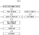
Fig. 1 is a flowchart showing steps in an automatic assembly method for a constant velocity universal joint according to one embodiment of the present invention. -
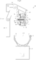
Fig. 2 is a partial cross-sectional front view illustrating a cassette insertion step in the above-mentioned method and illustrates a state before inserting a cassette into an inner periphery of an outer joint member. -
Fig. 3A is a diagram illustrating a retaining head, which is provided for a cassette cage part of a cassette insertion apparatus inFig. 2 , viewed from an axis direction of a shaft part. -
Fig. 3B is a cross-sectional view taken from line B-B inFig. 3A . -
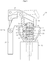
Fig. 4 is a partial cross-sectional front view illustrating a cassette insertion step in the above-mentioned method and is a diagram illustrating a state in which the cassette is inserted into the inner periphery of the outer joint member. -
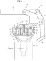
Fig. 5 is a partial cross-sectional front view illustrating the cassette insertion step in the above-mentioned method and is a diagram illustrating a state in which the cassette is rotated in the inner periphery of the outer joint member. -
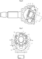
Fig. 6 is a cross-sectional view of the fixed type constant velocity universal joint. -
Fig. 7 is a cross-sectional view illustrating a view in which the cassette is inserted into the inner periphery of the outer joint member in the conventional automatic assembly method. -
Fig. 8 is a view of the cassette and the outer joint member inFig. 7 , viewed from above. -
Fig. 9 is a view in a state in which the cassette in the state illustrated inFig. 8 is rotated around an axis line of the outer joint member. -
Fig. 10 is a view in which the cassette in the state illustrated inFig. 9 is rotated around a rotational axis in a horizontal direction. - Hereinafter, an embodiment of the present invention will be described with reference to the accompanying drawings.
- An assembly method for a fixed type constant velocity universal joint according to one embodiment of the present invention is implemented successively through steps shown in
Fig. 1 . Hereinafter, each of the steps will be described in order. Note that since a configuration of the fixed type constant velocity universal joint assembled in the present embodiment is the same as that illustrated inFig. 6 , the description will be given by using the same reference signs and component names. - First, in an outer joint
member supply step 11, an outerjoint member 7 is conveyed into an automatic assembly apparatus. Then, in aphase matching step 12, theouter joint member 7 is rotated around a shaft center as needed, thereby locating each oftrack grooves 6 of theouter joint member 7 in a predetermined phase. The outerjoint member 7 for which phase matching of thetrack grooves 6 is made as mentioned above is transported to acassette insertion step 13. - On the other hand, in a
cassette supply step 14, acassette 5 which is constituted of an innerjoint member 2 and acage 4 is conveyed into the automatic assembly apparatus. Thecassette 5 is obtained by inserting the innerjoint member 2 into an inner periphery of thecage 4 and fitting an inner peripheral spherical surface of thecage 4 and an outer peripheral spherical surface of theinner joint member 2 so as to integrate theinner joint member 2 and thecage 4. Then, in apositioning step 15, positions ofpockets 3 of thecage 4 and positions oftrack grooves 1 of the innerjoint member 2 in a circumferential direction are matched. Thecassette 5 in which positioning of thepockets 3 and thetrack grooves 1 is made as mentioned above is transported to thecassette insertion step 13. - In the
cassette insertion step 13, thecassette 5 is assembled into an inner periphery of theouter joint member 7 by acassette insertion apparatus 30 illustrated inFig. 2 . Thecassette insertion apparatus 30 includes: an outer jointmember cage part 31 which retains the outerjoint member 7; acassette cage part 32 which retains thecassette 5; an ascending/descending driving part (not illustrated) as a linear driving part which moves thecassette cage part 32 in an axis direction of the outerjoint member 7 retained by the outer jointmember cage part 31; and a rotation driving part (not illustrated) which rotates thecassette cage part 32. In the present embodiment, as the rotation driving part, a first rotation driving part which rotates thecassette cage part 32 around a rotational axis in a vertical direction and a second rotation driving part which rotates thecassette cage part 32 around a rotational axis in a horizontal direction are provided. - The
cassette cage part 32 has: a retaininghead 33 to which thecassette 5 is attached; a lockingpart 34 which presses an end surface of thecage 4; and acylinder 36 which drives the lockingpart 34 via alink mechanism 35. - As illustrated in
Figs. 3A and 3B , the retaininghead 33 includes a headmain body 40 and a gripping means includingball plungers 50. In the present embodiment, theball plungers 50 are provided in a plurality of positions (three positions in an illustrated example) which are separated from one another in a circumferential direction. - The head
main body 40 has aplaty base part 41 and ashaft part 42 which protrudes from thebase part 41. In the illustrated example, thebase part 41 and theshaft part 42 are formed as separate bodies and are coupled by abolt 43. Thebase part 41 has large-diameter cylindrical surfaces 41a andshoulder surfaces 41b. The large-diametercylindrical surfaces 41a are provided coaxially with a cylindrical outerperipheral surface 42a of theshaft part 42. Each of the large-diametercylindrical surfaces 41a has a large diameter than a diameter of the cylindrical outerperipheral surface 42a of theshaft part 42. Each of the shoulder surfaces 41b extends from a base end of each of the large-diametercylindrical surfaces 41a (a left end inFig. 3B ) to an outer diameter. - Each of the
ball plungers 50 includes a cylindrical plungermain body 51, aball 52 as a pressing part, and a spring (not illustrated). Theball 52 is provided in a manner retractable from an opening portion of the plungermain body 51. The spring biases theball 52 to a side on which theball 52 protrudes from the opening portion of the plungermain body 51. In the illustrated example, the plungermain body 51 is inserted into a hole which is provided for the large-diameter cylindrical surfaces 41a of thebase part 41 of the headmain body 40. The plungermain body 51 is fixed to the headmain body 40 in a position where theball 52 slightly protrudes from each of the large-diametercylindrical surfaces 41a. - As illustrated in
Fig. 2 , the outerjoint member 7 is set in the outer jointmember cage part 31 in a state in which an opening portion of the outerjoint member 7 faces upward and each of thetrack grooves 6 is located in the predetermined phase. In the state in which the outerjoint member 7 is set in the outer jointmember cage part 31, rotation of the outerjoint member 7 around a shaft center O1 is regulated. - Then, in a state in which a shaft center O2 of the
shaft part 42 of the retaininghead 33 of thecassette cage part 32 is held horizontally, thecassette 5 in which the positioning of thepockets 3 and thetrack grooves 1 is made is attached to theshaft part 42. Specifically, theshaft part 42 of the retaininghead 33 is inserted into ashaft hole 9 of the innerjoint member 2 of the cassette 5 (seeFig. 3B ). An inner peripheral surface of the inner joint member 2 (crests of a spline hole in the illustrated example) and the cylindrical outerperipheral surface 42a of theshaft part 42 are fitted to each other. An end surface of the innerjoint member 2 is brought into contact with anend surface 41c of thebase part 41 of the headmain body 40 of the retaininghead 33. Thus, the innerjoint member 2 is located in a predetermined position on the retaininghead 33. - Simultaneously with this, the large-diameter cylindrical surfaces 41a of the
base part 41 of the headmain body 40 of the retaininghead 33 and acylindrical part 4a which is provided in an end portion of an inner peripheral surface of thecage 4 in an axis direction (a left end inFig. 3B ) are fitted to each other. And the end surface of thecage 4 is brought into contact with the shoulder surfaces 41b of thebase part 41. At this time, each of theballs 52 of theball plungers 50 which are provided for the retaininghead 33 is pushed to a side of the inner periphery by thecylindrical part 4a of the inner peripheral surface of the cage 4 (a side on which each of theballs 52 is retracted into the plunger main body 51) against elasticity of the spring. Thereby each of theballs 52 is pressed against thecylindrical part 4a of the inner peripheral surface of thecage 4. Thus, the inner peripheral surface of thecage 4 is gripped and rotation and movement of the inner peripheral surface of thecage 4 in the axis direction relative to the headmain body 40 of thecage 4 are regulated. A force of gripping the inner peripheral surface of thecage 4 by the ball plungers 50 (that is, the elasticity of the spring) is set to approximately a force with which thecassette 5 can be pulled from the retaininghead 33 by a person's hand. - Thereafter, the
cylinder 36 is extended, and thecage 4 is sandwiched by the lockingpart 34 and the shoulder surfaces 41b of the headmain body 40 from both sides in the axis direction (seeFig. 2 ). Note that as described above, since thecage 4 is retained by theball plungers 50, when there is no need in particular, the lockingpart 34, thecylinder 36 for driving the lockingpart 34, and thelink mechanism 35 may be omitted. In this case, thecassette cage part 32 can be simplified, and a step of driving the lockingpart 34 can be omitted. - As described above, in a state in which the
cassette 5 is retained by thecassette cage part 32, thecassette cage part 32 and thecassette 5 are descended by the ascending/descending driving part, thereby inserting thecassette 5 to the inner periphery of the outerjoint member 7 as illustrated inFig. 4 . At this time, thepockets 3 of thecage 4 on both ends in the horizontal direction are fitted toridges 6a, each of which is located between thetrack grooves 6 of the outer joint member 7 (seeFigs. 7 and8 ). Thereby, interference between thecage 4 and the outerjoint member 7 can be avoided. - Thereafter, the
cassette cage part 32 and thecassette 5 are rotated by the first rotation driving part with the shaft center O1 of the outerjoint member 7 as a center. And while an outer peripheral spherical surface of thecage 4 and an inner peripheral spherical surface of the outerjoint member 7 are being fitted to each other, positions of thepockets 3 of thecage 4 in the circumferential direction are matched with thetrack grooves 6 of the outer joint member 7 (seeFig. 9 ). Note that in a case where a number of theballs 8 is six, as illustrated inFig. 9 , a rotation angle of thecassette 5 is 30°. In a case where the number of theballs 8 is eight, the rotation angle of thecassette 5 is 22.5°. - Thereafter, by driving the
cylinder 36, the lockingpart 34 is retracted to a side on which the lockingpart 34 is separated from the cage 4 (see a chain line inFig. 4 ). Then, thecassette cage part 32 and thecassette 5 are rotated by the second rotation driving part by 90° with the rotational axis in the horizontal direction as a center, specifically, with a straight line L. The straight line L passes through an intersecting point of the shaft center O1 of the outerjoint member 7 and the shaft center O2 of thecassette 5 and is orthogonal to the shaft center O1 and the shaft center O2, as a center. Thus, as illustrated inFig. 5 , the shaft center O2 of thecassette 5 and the shaft center O1 of the outerjoint member 7 match each other, and thecassette 5 is housed in the inner periphery of the outerjoint member 7. - As described above, in a state in which the inner peripheral surface of the
cage 4 is gripped by the gripping means (ball plungers 50) which is provided for the retaininghead 33 of thecassette cage part 32, thecassette 5 is inserted into the inner periphery of the outerjoint member 7 and thecassette 5 is rotated in the inner periphery of the outerjoint member 7. Thus, the rotation of thecage 4 relative to the retaininghead 33 can be regulated even when thecage 4 and the outerjoint member 7 contact each other during operating thecassette 5 and the outerjoint member 7. On the other hand, since the innerjoint member 2 which is fitted to theshaft part 42 of the retaininghead 33 is located in the inner periphery of thecage 4, upon assembling thecassette 5 into the outerjoint member 7, no interference with the outerjoint member 7 is caused and no rotation relative to the retaininghead 33 is caused. As described above, relative rotation of thecage 4 and the innerjoint member 2 is regulated, and while positional deviation of thepockets 3 of thecage 4 and thetrack grooves 1 of the innerjoint member 2 is prevented, thecassette 5 can be assembled into the outerjoint member 7. - Thereafter, a sub-assembly of the outer
joint member 7 and thecassette 5 is transported to a ball insertion step 16 (seeFig. 1 ). In this step, theballs 8 are attached to ball tracks which are formed by thetrack grooves 6 of the outerjoint member 7 and thetrack grooves 1 of the innerjoint member 2, which face thetrack grooves 6, one by one. Specifically, one of thepockets 3 of thecage 4 is exposed outside the outerjoint member 7 by inclining thecassette 5, and theball 8 is inserted into the exposed one of thepockets 3. This work is conducted for all of thepockets 3, thereby assembling theballs 8 into all of the ball tracks. Thereafter, after undergoing of aninspection step 17, the fixed type constant velocity universal joint is discharged from the automatic assembly apparatus. - The present invention is not limited to the above-described embodiment. For example, the gripping means which grips the inner peripheral surface of the
cage 4 is not limited to the ball plungers 50. The gripping means may be configured by an elastic member such as rubber. For example, the elastic member can be provided for the large-diameter cylindrical surfaces 41a of the headmain body 40. In this case, thecage 4 is attached to the headmain body 40 while the elastic member is being elastically deformed by the inner peripheral surface of thecage 4. By pressing the elastic member against the inner peripheral surface of thecage 4, the inner peripheral surface of thecage 4 is gripped by elasticity of the elastic member. - In addition, although in the above-described embodiment, a case where the
balls 52 of theball plungers 50 in the three positions are pressed against the inner peripheral surface of thecage 4 and the inner peripheral surface of thecage 4 is thereby gripped is described, the present invention is not limited to the above-mentioned case. The inner peripheral surface of thecage 4 may be gripped by theballs 52 of theball plungers 50 and the large-diameter cylindrical surfaces 41a of thebase part 41 of the headmain body 40 in cooperation with each other. For example, theballs 52 of the twoball plungers 50 provided on a right side inFig. 3A and the large-diametercylindrical surface 41a on a left side inFig. 3A may grip the inner peripheral surface of thecage 4. In this case, theball plunger 50 on the left side inFig. 3A may be omitted. - In addition, although in the above-described embodiment, when the
cassette 5 retained by thecassette cage part 32 is inserted into the inner periphery of the outerjoint member 7, thecassette cage part 32 and thecassette 5 are descended, the present invention is not limited to this embodiment. For example, thecassette cage part 32 and thecassette 5 may be kept still and the outerjoint member 7 retained by the outer jointmember cage part 31 may be ascended. In addition, a relative movement direction of thecassette 5 and the outerjoint member 7 at this time is not limited to a vertical direction and may be a direction which inclines relative to the vertical direction (for example, a horizontal direction). - In addition, although in the above-described embodiment, when the
cassette 5 retained by thecassette cage part 32 is rotated in the inner periphery of the outerjoint member 7, thecassette cage part 32 and thecassette 5 are rotated, the present invention is not limited to this embodiment. Thecassette cage part 32 and thecassette 5 may be kept still and the outerjoint member 7 retained by the outer jointmember cage part 31 may be rotated. - In addition, the fixed type constant velocity universal joint to which the assembly method and the assembly apparatus according to the present invention are applicable is not limited to that illustrated in
Fig. 6 . For example, although inFig. 6 , a Rzeppa type constant velocity universal joint whosetrack grooves Fig. 6 , thetrack grooves Fig. 6 , the number of the balls is six, the present invention is not limited to this, and for example, the number of the balls may be eight. -
- 1
- Track grooves
- 2
- Inner joint member (inside joint member)
- 3
- Pockets
- 4
- Cage
- 4a
- Cylindrical part
- 5
- Cassette
- 6
- Track grooves
- 7
- Outer joint member (outside joint member)
- 8
- Balls
- 9
- Shaft hole
- 10
- Shaft
- 30
- Cassette insertion apparatus
- 31
- Outer joint member cage part
- 32
- Cassette cage part
- 33
- Retaining head
- 34
- Locking part
- 35
- Link mechanism
- 36
- Cylinder
- 40
- Head main body
- 41
- Base part
- 42
- Shaft part
- 43
- Bolt
- 50
- Ball plungers (gripping means)
- 51
- Plunger main body
- 52
- Balls (pressing part)
Claims (4)
- An automatic assembly apparatus (30) for assembling a fixed type constant velocity universal joint, the fixed type constant velocity universal joint comprising:an inner joint member (2) which has a plurality of track grooves (1) and a shaft hole (9) for attaching a shaft (10);an outer joint member (7) which has a plurality of track grooves (6);a plurality of balls (8) which engage with the track grooves (1) of the inner joint member (2) and the track grooves (6) of the outer joint member (7) to transmit torque; anda cage (4) having a plurality of pockets (3) which house the plurality of balls (8) and fitting an outer peripheral spherical surface of the inner joint member (2) and an inner peripheral spherical surface of the outer joint member (7),characterized in that
the automatic assembly apparatus (30) comprises:an outer joint member cage part (31) which retains the outer joint member (7);a cassette cage part (32) which retains a cassette (5) being configured by fitting an inner peripheral spherical surface of the cage (4) and an outer peripheral spherical surface of the inner joint member (2);a linear driving part which moves the cassette cage part (32) in an axis direction of the outer joint member (7) relative to the outer joint member cage part (31); anda rotation driving part which rotates the cassette cage part (32) relative to the outer joint member cage part (31), andthe cassette cage part (32) includes a shaft part (42) which fits the shaft hole (9) of the inner joint member (2) and a gripping means (50) which grips an inner peripheral surface of the cage (4). - The automatic assembly apparatus (30) for assembling a fixed type constant velocity universal joint according to claim 1, characterized in that the gripping means (50) includes a pressing part (52) which is pressed against the inner peripheral surface of the cage (4).
- The automatic assembly apparatus for assembling a fixed type constant velocity universal joint according to claim 2, characterized in that the pressing part (52) is pressed against a cylindrical part (4a) being provided for the inner peripheral surface of the cage (4).
- An automatic assembly method for automatically assembling a fixed type constant velocity universal joint, the fixed type constant velocity universal joint comprising:an inner joint member (2) which has a plurality of track grooves (1) and a shaft hole (9) for attaching a shaft (10);an outer joint member (7) which has a plurality of track grooves (6);a plurality of balls (8) which engage with the track grooves (1) of the inner joint member (2) and the track grooves (6) of the outer joint member (7) to transmit torque; anda cage (4) having a plurality of pockets (3) which house the plurality of balls (8) and fitting an outer peripheral spherical surface of the inner joint member (2) and an inner peripheral spherical surface of the outer joint member(7),characterized in that
the automatic assembly method comprises the successive steps of:conveying, into an automatic assembly apparatus (30), a cassette (5) being configured by fitting an inner peripheral spherical surface of the cage (4) and the outer peripheral spherical surface of the inner joint member (2);retaining the cassette (5) by fitting a shaft part (42) being provided for a cassette cage part (32) of the automatic assembly apparatus (30) into the shaft hole (9) of the inner joint member (2) and by gripping the inner peripheral surface of the cage (4) by a gripping means (50) being provided for the cassette cage part (32);inserting the cassette (5) into an inner periphery of the outer joint member (7) in a state in which an axis line (O2) of the cassette (5) being retained by the cassette cage part (32) and an axis line (O1) of the outer joint member (7) are made to be orthogonal to each other;rotating the cassette (5) being retained by the cassette cage part (32) relative to the outer joint member (7) in the inner periphery of the outer joint member (7); andinserting the balls (8) into the pockets (3) of the cage (4).
Applications Claiming Priority (1)
| Application Number | Priority Date | Filing Date | Title |
|---|---|---|---|
| JP2020158602A JP7390999B2 (en) | 2020-09-23 | 2020-09-23 | Automatic assembly device and method for fixed constant velocity universal joints |
Publications (1)
| Publication Number | Publication Date |
|---|---|
| EP3978771A1 true EP3978771A1 (en) | 2022-04-06 |
Family
ID=77640456
Family Applications (1)
| Application Number | Title | Priority Date | Filing Date |
|---|---|---|---|
| EP21194802.1A Pending EP3978771A1 (en) | 2020-09-23 | 2021-09-03 | Automatic assembly apparatus and automatic assembly method for fixed type constant velocity universal joint |
Country Status (2)
| Country | Link |
|---|---|
| EP (1) | EP3978771A1 (en) |
| JP (1) | JP7390999B2 (en) |
Cited By (2)
| Publication number | Priority date | Publication date | Assignee | Title |
|---|---|---|---|---|
| EP4620613A4 (en) * | 2022-11-15 | 2026-02-18 | Ntn Toyo Bearing Co Ltd | DEVICE FOR MOUNTING A CONTRACTUAL VENTILATION JOINT AND MOUNTING PROCEDURES |
| EP4632244A4 (en) * | 2022-12-08 | 2026-03-25 | Ntn Toyo Bearing Co Ltd | AUTOMATIC BALL INSERTION METHOD FOR A CONVERTER ROTATION JOINT |
Citations (4)
| Publication number | Priority date | Publication date | Assignee | Title |
|---|---|---|---|---|
| JPH03213230A (en) * | 1990-01-12 | 1991-09-18 | Mitsubishi Automob Eng Co Ltd | Method and device for building ball in rzeppa joint |
| JPH03256628A (en) * | 1990-03-07 | 1991-11-15 | Mitsubishi Automob Eng Co Ltd | Automatic assembling machine of pzeppa joint |
| JPH04193436A (en) * | 1990-11-27 | 1992-07-13 | Honda Motor Co Ltd | Ball inserting method into ball cage for double offset type constant velocity ball joint assembling process and tilting device for inner and ball cage |
| JPH0615885B2 (en) | 1985-08-09 | 1994-03-02 | エヌティエヌ株式会社 | Automatic assembly method for constant velocity ball joints |
Family Cites Families (1)
| Publication number | Priority date | Publication date | Assignee | Title |
|---|---|---|---|---|
| JPH0832388B2 (en) * | 1989-12-28 | 1996-03-29 | 三菱自動車エンジニアリング株式会社 | Method and apparatus for assembling a cage assembly and outer ring of a Rzeppa joint |
-
2020
- 2020-09-23 JP JP2020158602A patent/JP7390999B2/en active Active
-
2021
- 2021-09-03 EP EP21194802.1A patent/EP3978771A1/en active Pending
Patent Citations (4)
| Publication number | Priority date | Publication date | Assignee | Title |
|---|---|---|---|---|
| JPH0615885B2 (en) | 1985-08-09 | 1994-03-02 | エヌティエヌ株式会社 | Automatic assembly method for constant velocity ball joints |
| JPH03213230A (en) * | 1990-01-12 | 1991-09-18 | Mitsubishi Automob Eng Co Ltd | Method and device for building ball in rzeppa joint |
| JPH03256628A (en) * | 1990-03-07 | 1991-11-15 | Mitsubishi Automob Eng Co Ltd | Automatic assembling machine of pzeppa joint |
| JPH04193436A (en) * | 1990-11-27 | 1992-07-13 | Honda Motor Co Ltd | Ball inserting method into ball cage for double offset type constant velocity ball joint assembling process and tilting device for inner and ball cage |
Cited By (2)
| Publication number | Priority date | Publication date | Assignee | Title |
|---|---|---|---|---|
| EP4620613A4 (en) * | 2022-11-15 | 2026-02-18 | Ntn Toyo Bearing Co Ltd | DEVICE FOR MOUNTING A CONTRACTUAL VENTILATION JOINT AND MOUNTING PROCEDURES |
| EP4632244A4 (en) * | 2022-12-08 | 2026-03-25 | Ntn Toyo Bearing Co Ltd | AUTOMATIC BALL INSERTION METHOD FOR A CONVERTER ROTATION JOINT |
Also Published As
| Publication number | Publication date |
|---|---|
| JP2022052301A (en) | 2022-04-04 |
| JP7390999B2 (en) | 2023-12-04 |
Similar Documents
| Publication | Publication Date | Title |
|---|---|---|
| US5807180A (en) | Constant velocity universal joint shaft and inner race combination | |
| US7201664B2 (en) | Fixed constant velocity joint | |
| US8808097B2 (en) | Fixed type constant velocity universal joint | |
| US8262489B2 (en) | Constant velocity joint attachment method | |
| US20080254903A1 (en) | Opposed path joint | |
| KR970007658B1 (en) | Constant velocity joint | |
| US20250083313A1 (en) | Robotic systems, methods, and devices for grappling and actuating a payload | |
| EP3084245B1 (en) | A constant velocity joint | |
| JPH11336782A (en) | Constant-speed push-in fitting with disassembly prevention means | |
| US20140080612A1 (en) | Constant velocity universal joint | |
| JP2014238165A (en) | Pinion direct attached type rzeppa joint | |
| EP2172666B1 (en) | Joint for steering | |
| JP7390999B2 (en) | Automatic assembly device and method for fixed constant velocity universal joints | |
| JPH0754855A (en) | Quick disconnect type constant velocity universal joint | |
| US8066575B2 (en) | Constant velocity universal joint and inner member of the same | |
| EP2505863A1 (en) | Stationary constant-velocity universal joint | |
| JPS60174143A (en) | Variable speed apparatus of medical handpiece | |
| EP3450783A1 (en) | Constant velocity universal joint | |
| JP2002181064A (en) | Constant velocity fixed ball joint as opposed track joint | |
| US5184979A (en) | Quick disconnect constant velocity universal joint | |
| US20040106459A1 (en) | Constant velocity joint | |
| EP3573789B1 (en) | An alignment tool for aligning bores in structural members | |
| KR20060047416A (en) | High Speed High Refractive Universal Joint | |
| JPS61284333A (en) | Toothed parts assembly device | |
| CN223617625U (en) | Electric impact ratchet wrench |
Legal Events
| Date | Code | Title | Description |
|---|---|---|---|
| PUAI | Public reference made under article 153(3) epc to a published international application that has entered the european phase |
Free format text: ORIGINAL CODE: 0009012 |
|
| STAA | Information on the status of an ep patent application or granted ep patent |
Free format text: STATUS: THE APPLICATION HAS BEEN PUBLISHED |
|
| AK | Designated contracting states |
Kind code of ref document: A1 Designated state(s): AL AT BE BG CH CY CZ DE DK EE ES FI FR GB GR HR HU IE IS IT LI LT LU LV MC MK MT NL NO PL PT RO RS SE SI SK SM TR |
|
| STAA | Information on the status of an ep patent application or granted ep patent |
Free format text: STATUS: REQUEST FOR EXAMINATION WAS MADE |
|
| 17P | Request for examination filed |
Effective date: 20221006 |
|
| RBV | Designated contracting states (corrected) |
Designated state(s): AL AT BE BG CH CY CZ DE DK EE ES FI FR GB GR HR HU IE IS IT LI LT LU LV MC MK MT NL NO PL PT RO RS SE SI SK SM TR |
|
| STAA | Information on the status of an ep patent application or granted ep patent |
Free format text: STATUS: EXAMINATION IS IN PROGRESS |
|
| 17Q | First examination report despatched |
Effective date: 20240619 |
|
| 17Q | First examination report despatched |
Effective date: 20240627 |