EP3978271A1 - Tire - Google Patents
Tire Download PDFInfo
- Publication number
- EP3978271A1 EP3978271A1 EP20814475.8A EP20814475A EP3978271A1 EP 3978271 A1 EP3978271 A1 EP 3978271A1 EP 20814475 A EP20814475 A EP 20814475A EP 3978271 A1 EP3978271 A1 EP 3978271A1
- Authority
- EP
- European Patent Office
- Prior art keywords
- interlink
- portions
- springs
- spring
- rim member
- Prior art date
- Legal status (The legal status is an assumption and is not a legal conclusion. Google has not performed a legal analysis and makes no representation as to the accuracy of the status listed.)
- Withdrawn
Links
- 238000006073 displacement reaction Methods 0.000 claims description 16
- 238000010586 diagram Methods 0.000 description 15
- 239000002184 metal Substances 0.000 description 6
- 238000000034 method Methods 0.000 description 6
- 239000000463 material Substances 0.000 description 4
- 230000000452 restraining effect Effects 0.000 description 3
- 230000000694 effects Effects 0.000 description 2
- 238000003780 insertion Methods 0.000 description 2
- 230000037431 insertion Effects 0.000 description 2
- 238000012986 modification Methods 0.000 description 2
- 230000004048 modification Effects 0.000 description 2
- 239000011347 resin Substances 0.000 description 2
- 229920005989 resin Polymers 0.000 description 2
- 238000005452 bending Methods 0.000 description 1
- 230000008602 contraction Effects 0.000 description 1
- 230000002452 interceptive effect Effects 0.000 description 1
- 230000007246 mechanism Effects 0.000 description 1
- 230000000149 penetrating effect Effects 0.000 description 1
- 230000035515 penetration Effects 0.000 description 1
- 230000009467 reduction Effects 0.000 description 1
- 230000004044 response Effects 0.000 description 1
Images






Classifications
-
- B—PERFORMING OPERATIONS; TRANSPORTING
- B60—VEHICLES IN GENERAL
- B60B—VEHICLE WHEELS; CASTORS; AXLES FOR WHEELS OR CASTORS; INCREASING WHEEL ADHESION
- B60B25/00—Rims built-up of several main parts ; Locking means for the rim parts
- B60B25/04—Rims with dismountable flange rings, seat rings, or lock rings
- B60B25/045—Rims with dismountable flange rings, seat rings, or lock rings on both sides
-
- B—PERFORMING OPERATIONS; TRANSPORTING
- B60—VEHICLES IN GENERAL
- B60B—VEHICLE WHEELS; CASTORS; AXLES FOR WHEELS OR CASTORS; INCREASING WHEEL ADHESION
- B60B25/00—Rims built-up of several main parts ; Locking means for the rim parts
- B60B25/002—Rims split in circumferential direction
- B60B25/006—Rims split symmetrically
-
- B—PERFORMING OPERATIONS; TRANSPORTING
- B60—VEHICLES IN GENERAL
- B60C—VEHICLE TYRES; TYRE INFLATION; TYRE CHANGING; CONNECTING VALVES TO INFLATABLE ELASTIC BODIES IN GENERAL; DEVICES OR ARRANGEMENTS RELATED TO TYRES
- B60C7/00—Non-inflatable or solid tyres
- B60C7/06—Non-inflatable or solid tyres made of metal
-
- B—PERFORMING OPERATIONS; TRANSPORTING
- B60—VEHICLES IN GENERAL
- B60C—VEHICLE TYRES; TYRE INFLATION; TYRE CHANGING; CONNECTING VALVES TO INFLATABLE ELASTIC BODIES IN GENERAL; DEVICES OR ARRANGEMENTS RELATED TO TYRES
- B60C7/00—Non-inflatable or solid tyres
- B60C7/10—Non-inflatable or solid tyres characterised by means for increasing resiliency
- B60C7/14—Non-inflatable or solid tyres characterised by means for increasing resiliency using springs
- B60C7/16—Non-inflatable or solid tyres characterised by means for increasing resiliency using springs of helical or flat coil form
- B60C7/18—Non-inflatable or solid tyres characterised by means for increasing resiliency using springs of helical or flat coil form disposed radially relative to wheel axis
-
- B—PERFORMING OPERATIONS; TRANSPORTING
- B60—VEHICLES IN GENERAL
- B60C—VEHICLE TYRES; TYRE INFLATION; TYRE CHANGING; CONNECTING VALVES TO INFLATABLE ELASTIC BODIES IN GENERAL; DEVICES OR ARRANGEMENTS RELATED TO TYRES
- B60C7/00—Non-inflatable or solid tyres
- B60C7/24—Non-inflatable or solid tyres characterised by means for securing tyres on rim or wheel body
Definitions
- the disclosure relates to a tire.
- Patent Literature (PTL) 1 discloses a tire in which a respective plurality of coil springs are interlaced with other coil springs and secured to annular rims to form a toroidal shape as a whole.
- the tire in a case in which an elastic deformable portion such as a coil spring comes off from an annular rim, the tire may not be able to maintain its shape and may cease to function as a tire.
- a tire according to the disclosure is a tire including: a plurality of rim members disposed at different positions on the same axis; a plurality of body springs that connect between the respective plurality of rim members; and an interlink member that interlinks the adjacent body springs, wherein each of the plurality of body springs includes: an elastic deformable portion; and latch portions provided at both ends of the elastic deformable portion, the latch portions having a different shape from the elastic deformable portion, and the latch portions are latched on the rim members.
- FIG. 1 is an external perspective view of a tire according to an embodiment of the disclosure.
- a tire 1 according to the present embodiment includes a wheel portion 10 having a rim portion, and a grounding deformable portion 20 that is deformable while being grounded.
- FIG. 2 is an external perspective view of the wheel portion 10 of FIG. 1 .
- the wheel portion 10 is provided with a plurality of rim members.
- the wheel portion 10 is provided with, as the rim members, a first rim member 101 and a second rim member 102.
- the number of the plurality of rim members provided in the wheel portion 10 does not necessarily have to be two as in the present embodiment, but can be two or more.
- the wheel portion 10 is further provided with a plurality of connection members 103.
- the first rim member 101 and the second rim member 102 are made of metal or resin.
- the first rim member 101 and the second rim member 102 are disposed at different positions on the same axis.
- the first rim member 101 and the second rim member 102 are each formed in an annular shape.
- the first rim member 101 and the second rim member 102 are configured to be the same size and shape.
- the first rim member 101 and the second rim member 102 may be configured in different sizes or shapes.
- the outer diameter of the first rim member 101 and the second rim member 102 may be determined according to the size of the tire 1 required.
- connection members 103 are members that connect between the first rim member 101 and the second rim member 102.
- the connection members 103 are made of metal or resin.
- the wheel portion 10 is provided with six connection members 103, but the number of the connection members 103 provided in the wheel portion 10 is not limited thereto.
- the plurality of connection members 103 are attached to one side of the annular first rim member 101 and one side of the annular second rim member 102.
- the side on which the connection members 103 are attached to the first rim member 101 and the second rim member 102 is referred to as an inner side in a tire width direction, and the side on which the connection members 103 are not attached is referred to as an outer side in the tire width direction.
- the first rim member 101 and the second rim member 102 have, in inner surfaces in the tire width direction, engagement receiving portions 105 (see FIG. 5 ) in which body springs 201 of the grounding deformable portion 20 are engaged. Details of the engagement receiving portions and an aspect of engagement will be described later.
- engagement refers to being fitted together
- latching refers broadly to being fastened together, including being fitted together.
- a support member 104 is attached to each of the first rim member 101 and the second rim member 102.
- the support member 104 is a member that maintains a state of engaging the grounding deformable portion 20 in the engagement receiving portions 105 (see FIG. 5 ).
- the support members 104 can be secured to the inner side of the first rim member 101 and the second rim member 102 in the tire width direction using, for example, bolts.
- the grounding deformable portion 20 is configured with members including elastic deformable portions.
- the grounding deformable portion 20 includes two kinds of members: body springs 201 and interlink springs 211.
- the body springs 201 and the interlink springs 211 are made of metal.
- FIG. 3 is a schematic diagram illustrating an example of the body spring 201 that configures the grounding deformable portion 20 of FIG. 1 .
- the body springs 201 connect between the plurality of rim members.
- the body springs 201 connect between the first rim member 101 and the second rim member 102.
- the body springs 201 may connect at least one of spaces between the adjacent rim members, though it is preferable that the body springs 201 connect the respective spaces between the adjacent rim members in a manner similar to the manner of connecting between the first rim member 101 and the second rim member 102 described herein.
- the body spring 201 has an elastic deformable portion 202 and latch portions 203.
- the elastic deformable portion 202 is constituted of a coil spring.
- the coil spring refers to a spring that deforms elastically in response to a load and is coiled (spirally wound) around a predetermined axis.
- the elastic deformable portion 202 that is made of a suitable material and has appropriate elasticity can be used according to the size and weight of the tire 1, required properties of the grounding deformable portion 20, and the like.
- the latch portions 203 are provided at both ends of the elastic deformable portion 202.
- the latch portions 203 latch the body spring 201 to the wheel portion 10.
- the latch portions 203 have a different shape from the elastic deformable portion 202. That is, in the present embodiment, the latch portions 203 have a shape different from a coil shape.
- the latch portions 203 are constituted of members integral with the elastic deformable portion 202. That is, in the present embodiment, as illustrated in FIG. 3 , for example, a material composing the elastic deformable portion 202 extends from both the ends of the elastic deformable portion 202 to configure the latch portions 203.
- the latch portions 203 include straight portions 203a that are formed in a linear shape and are joined to both the ends of the elastic deformable portion 202. Also in the present embodiment, as illustrated in FIG. 3 , for example, the latch portions 203 include, at tip ends of the straight portions 203a, bent portions 203b that are bent with respect to the straight portions 203a. In the present embodiment, the bent portions 203b are bent orthogonally with respect to the straight portions 203a in a side view of the body spring 201 (in a plane containing an axis of the body spring 201).
- FIGS. 4 to 6 an aspect of engaging the body springs 201 in the wheel portion 10 according to the present embodiment will be described in detail.
- One of the latch portions 203 provided at both the ends of the body spring 201 is engaged in the first rim member 101, and the other latch portion 203 is engaged in the second rim member 102.
- An example of a case in which one of the latch portions 203 is engaged in the first rim member 101 will be described here, but the other latch portion 203 can be engaged in the second rim member 102 in the same manner.
- FIG. 4 is a schematic diagram illustrating an example of an aspect of engaging the body springs 201 in the first rim member 101, in which an engagement state of the body springs 201 is viewed from the inner side of the first rim member 101 in the tire width direction.
- FIG. 4 illustrates only part of the first rim member 101 in which the body springs 201 are engaged, but the body springs 201 are practically engaged, as illustrated in FIG. 4 , over the entire circumference of the first rim member 101 in the first rim member 101.
- the body springs 201 can be engaged in the first rim member 101 by engaging the latch portions 203 in the engagement receiving portions 105 provided in a surface of the first rim member 101 on the inner side in the tire width direction.
- the engagement receiving portion 105 is configured as a hole into which the bent portion 203b of the latch portion 203 is insertable. Inserting the bent portions 203b into the holes of the engagement receiving portions 105 allows the body springs 201 to be engaged in the first rim member 101.
- the support member 104 is attached to the inner side of the first rim member 101 in the tire width direction in order to firmly secure the engagement state of the latch portions 203.
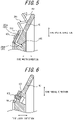
- FIG. 5 is a cross sectional view taken on the line A-A of FIG. 4 , and specifically, a cross sectional view of the first rim member 101 at a point including the engagement receiving portion.
- the first rim member 101 has the engagement receiving portion 105.
- the engagement receiving portion 105 is configured as a hole into which the bent portion 203b is insertable.
- the engagement receiving portion 105 is configured as a bottomed hole.
- the length of the hole (depth of the hole) of the engagement receiving portion 105 in an extending direction is preferably longer than the length of the bent portion 203b. As a result, the entire bent portion 203b can be inserted into the engagement receiving portion 105, and the engagement state becomes more stable.
- the engagement receiving portion 105 may be configured as a bottomless hole (through hole).
- the shape of cross section of the hole of the engagement receiving portion 105 is not limited as long as the bent portion 203b is insertable thereinto, and may be, for example, an ellipse, an oval, a rectangle, a polygon, or the like.
- the shape and size of cross section of the hole are approximately the same as the shape and size of cross section of the bent portion 203b.
- the body spring 201 is arranged such that, in a state of inserting the bent portion 203b into the engagement receiving portion 105, the elastic deformable portion 202 is positioned, except for at least part, at a radially outer side (upper side in FIGS. 5 and 6 ) of the tire of the annular first rim member 101.
- the support member 104 is attached to the inner side (left side in FIGS. 5 and 6 ) of the first rim member 101 in the tire width direction.
- the support member 104 is attached, as illustrated in FIG.
- the support member 104 is preferably attached in such a position as to block the hole of the engagement receiving portion 105 in a state of not inserting the body spring 201. Also, as illustrated in FIG. 5 , for example, the support member 104 is secured to the first rim member 101 so as to retain the straight portion 203a of the latch portion 203 on the inner surface of the first rim member 101 in the tire width direction. In this manner, the engagement state of the latch portion 203 is stably secured by the support member 104.
- FIG. 6 is a cross sectional view of FIG. 4 taken on the line B-B, and specifically, a cross sectional view of the first rim member 101 at a point including the bolt 106 for securing the support member 104.
- the support member 104 is secured to the first rim member 101 by the bolt 106.
- the support member 104 may be secured to the first rim member 101 at a position between (in the middle of) the two body springs 201 that are engaged in the first rim member 101.
- one bolt hole 107 for securing the bolt 106 is formed between the two adjacent engagement receiving portions 105 in a circumferential direction of the annular first rim member 101.
- the support member 104 may be constituted of a single annular member or as a plurality of divided members that form an annular shape in their entirety. In such a case, the support members 104 may be disposed so as to contact each other at their ends in the circumferential direction, or may be arranged with leaving appropriate clearances. In a case in which the support member 104 is constituted of the plurality of divided members, each member has, for example, the shape of a sector.
- one of the latch portions 203 (more specifically, the bent portions 203b) of each of the body springs 201 is engaged in the engagement receiving portion 105 of the first rim member 101, and the support member 104 is secured to the first rim member 101, in the above-described aspect.
- the latch portions 203 are latched on the first rim member 101.
- the other latch portion 203 (more specifically, the bent portion 203b) of each of the body springs 201 is engaged in an engagement receiving portion of the second rim member 102, and the support member 104 is secured to the second rim member 102.
- latch portions 203 are latched on the second rim member 102.
- one and the other latch portions 203 of one body spring 201 may be engaged, in the first rim member 101 and the second rim member 102, in the engagement receiving portions that are positioned on a straight line in an axial direction of the first rim member 101 and the second rim member 102.
- two latch portions 203 of one body spring 201 may be secured to the first rim member 101 and the second rim member 102 at the same position with respect to the circumferential direction.
- the two latch portions 203 of the one body spring 201 may not necessarily be secured at the same position in the circumferential direction, with respect to the first rim member 101 and the second rim member 102.
- the number and intervals of the body springs 201 to be engaged in the first rim member 101 and the second rim member 102 may be determined as appropriate according to the size and weight of the tire 1, required properties of the grounding deformable portion 20, and the like.
- the number and intervals of the bolts 106 used to attach the support members 104 to the first rim member 101 and the second rim member 102 may also be determined as appropriate.
- the bolt 106 does not necessarily have to be attached to every space between two of the engagement receiving portions 105 adjacent in the circumferential direction as in the present embodiment.
- the plurality of body springs 201 which are engaged in the wheel portion 10 in this manner, are interlinked with the interlink springs 211 to form the grounding deformable portion 20.
- the interlink spring 211 functions as an interlink member to interlink the adjacent body springs 201.
- FIG. 7 is a schematic diagram illustrating an example of the interlink spring 211 composing the grounding deformable portion 20 of FIG. 1 .
- the interlink spring 211 has an elastic deformable portion 212 and a limitation portion 213.
- the interlink spring 211 is disposed between the two body springs 201 adjacent in the circumferential direction, which are engaged in the wheel portion 10, and is interlaced with the two body springs 201 so as to be interlinked with the body springs 201.
- the elastic deformable portion 212 is constituted of a coil spring.
- the elastic deformable portion 212 that is made of a suitable material and has appropriate elasticity can be used according to the size and weight of the tire 1, required properties of the grounding deformable portion 20, and the like. It is preferable that the diameter of the coil spring constituting the elastic deformable portion 212 is close to the diameter of the coil spring constituting the elastic deformable portion 202 of the body spring 201.
- the diameter of the coil spring is the diameter of a circumscribed circle in the case of viewing the coil spring from an axial direction, and the same applies hereinafter.
- both the diameter of the coil spring constituting the elastic deformable portion 202 and the diameter of the coil spring constituting the elastic deformable portion 212 can be 15 mm to 25 mm, e.g. 20 mm or the like.
- the limitation portion 213 is provided at one end of the elastic deformable portion 212. No other mechanism is provided at the other end of the elastic deformable portion 212 where the limitation portion 213 is not provided, and thus the elastic deformable portion 212 has an open shape at the other end.
- the limitation portion 213 limits displacement of the interlink spring 211, which is to be interlinked with the body springs 201, with respect to the body springs 201.
- the limitation portion 213 limits displacement of the interlink spring 211 in at least one direction relative to the body springs 201.
- the interlinked position of the interlink spring 211 is determined and secured. That is, an interlinked state of the interlink spring 211 with respect to the body springs 201 is positioned and secured.
- the limitation portion 213 has a different shape from the elastic deformable portion 212. That is, in the present embodiment, the limitation portion 213 has a different shape from a coil shape.
- the limitation portion 213 is constituted of a member integral with the elastic deformable portion 212. That is, in the present embodiment, as illustrated in FIG. 7 , for example, a material of the elastic deformable portion 212 extends from one end of the elastic deformable portion 212 to form the limitation portion 213.
- the limitation portion 213 has a ring-shaped portion formed with a wire, which forms the elastic deformable portion 212, being bent into a ring shape.
- the ring-shaped portion is formed so as to have a central axis in a direction intersecting the direction of an axis A of the elastic deformable portion 212.
- the ring-shaped portion of the limitation portion 213 may be of any size capable of limiting displacement of the interlink spring 211.
- the ring-shaped portion of the limitation portion 213 may be configured to have a diameter of 0.5 to 1.0 times the diameter of the elastic deformable portion 212.
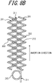
- FIGS. 8A and 8B are schematic diagrams for explaining an example of the method for interlinking the interlink spring 211 with the body springs 201.
- the interlink spring 211 is interlinked with the two adjacent body springs 201 by hooking the elastic deformable portion 212 on the elastic deformable portions 202 of the body springs 201, which are engaged in the wheel portion 10, in such a manner as to be interlaced with the two adjacent body springs 201.
- the interlink spring 211 is interlinked with the body springs 201 so as to restrict the relative displacement between the two body springs 201 adjacent in the circumferential direction.
- the interlink spring 211 is gradually interlaced with the two adjacent body springs 201 by being inserted into the body springs 201 in such a manner as to move forward while rotating, from the side of the other end on which the limitation portion 213 is not provided.
- the interlink spring 211 does not move in an insertion direction beyond the position at which the limitation portion 213 contacts the body spring 201. In particular, the interlink spring 211 does not move forward (move in the insertion direction) after the ring-shaped portion of the limitation portion 213 contacts the body spring 201, even if the interlink spring 211 is attempted to be moved forward while being rotated.
- the limitation portion 213 limits displacement of the interlink spring 211 in at least one direction relative to the body springs 201. In this manner, the limitation portion 213 positions and secures an interlinked state of the interlink spring 211 with respect to the body springs 201. In addition, the interlink spring 211 interlinked with the body springs 201 is prevented from coming off from the body springs 201.
- At least one of the two ends of the interlink spring 211 is not secured to the first rim member 101 and the second rim member 102. In the present embodiment, neither of the ends of the interlink spring 211 is secured to the first rim member 101 and the second rim member 102. In other words, in the present embodiment, the interlink spring 211 is not secured at either end. However, only one of the ends of the interlink spring 211 may be secured to the first rim member 101 or the second rim member 102. In this case, the other end of the interlink spring 211, which is opposite to the one end of the interlink spring 211 on which the limitation portion 213 is provided, is secured to the first rim member 101 or the second rim member 102.
- all the body springs 201, which are engaged in the wheel portion 10, are interlinked with the interlink springs 211 each disposed between the two adjacent body springs 201.
- the tire 1 is configured in this manner. In other words, in the present embodiment, every body spring 201 of the grounding deformable portion 20 of the tire 1 is interlinked with the two interlink springs 211, and every interlink spring 211 of the grounding deformable portion 20 of the tire 1 is interlinked with the two body springs 201.
- the interlink springs 211 are each interlinked between the two adjacent body springs 201, so even in the case of applying a load to the tire 1, the distance between the body springs 201 does not widen too much, and the tire 1 can easily maintain its function as a tire.
- the limitation portions 213 can limit displacement of the interlink springs 211 in at least one direction relative to the body springs 201 in the tire 1, so that the interlink springs 211 interlinked with the body springs 201 are prevented from coming off from the body springs 201. Therefore, the interlink springs 211 are mainly located in a grounding area of the tire 1, and are not located in the vicinity of secured positions between the first rim member 101 and the body springs 201 and between the second rim member 102 and the body springs 201.
- the elastic deformable portions 202 of the body springs 201 and the elastic deformable portions 212 of the interlink springs 211 are located in the grounding area of the tire 1, while only the elastic deformable portions 202 of the body springs 201 are located in the vicinity of the secured positions between the first rim member 101 and the body springs 201 and between the second rim member 102 and the body springs 201.
- the elastic deformable portions 202 of the body springs 201 and the elastic deformable portions 212 of the interlink springs 211 serve to prevent a reduction in load durability performance of the tire 1, while a congested state of the elastic deformable portions 202 at the secured positions to the first rim member 101 and the second rim member 102 is improved.
- the interlink spring 211 that joins the two body springs 201 can be inserted from the side of the first rim member 101 or from the side of the second rim member 102 in the axial direction of the wheel portion 10 (i.e. the direction of a rotational axis of the tire 1). It is preferable that half of the plurality of interlink springs 211 in the tire 1 are inserted from the side of the first rim member 101, and the other half thereof are inserted from the side of the second rim member 102.
- the limitation portions 213 of the interlink springs 211 are evenly arranged on both sides in the axial direction of the tire 1, thus easily striking a balance of the tire 1 and preventing the limitation portions 213 from being congested in only one direction in the axial direction of the tire 1.
- the plurality of interlink springs 211 are more preferably inserted such that, as illustrated as an example in FIG. 8C , the interlink springs 211 that are adjacent to each other in the circumferential direction of the grounding deformable portion 20 are inserted from different directions. This further facilitates striking a balance of the tire 1.
- the tire 1 may also be provided with a connection member that connects the ring-shaped portions of the limitation portions 213 of the plurality of interlink springs 211.
- the connection member is constituted of a wire, for example. For example, suppose that half of the plurality of interlink springs 211 are inserted from the side of the first rim member 101 and the other half thereof are inserted from the side of the second rim member 102. In this case, the limitation portions 213 of the interlink springs 211 inserted from the side of the first rim member 101 are located on the side of the first rim member 101, and the limitation portions 213 of the interlink springs 211 inserted from the side of the second rim member 102 are located on the side of the second rim member 102.
- the tire 1 may have two wires, that is, a wire for connecting the ring-shaped portions of the plurality of limitation portions 213 located on the side of the first rim member 101 and a wire for connecting the ring-shaped portions of the plurality of limitation portions 213 located on the side of the second rim member 102.
- the wire for connecting the ring-shaped portions of the plurality of limitation portions 213 located on the side of the first rim member 101 is provided, for example, along the circumferential direction of the wheel portion 10 so as to pass through central portions (openings formed by the ring-shaped portions) of all the ring-shaped portions of the plurality of limitation portions 213 located on the side of the first rim member 101.
- the wire for connecting the ring-shaped portions of the plurality of limitation portions 213 located on the side of the second rim member 102 is provided, for example, along the circumferential direction of the wheel portion 10 so as to pass through central portions of all the ring-shaped portions of the plurality of limitation portions 213 located on the side of the second rim member 102.
- Such a wire is formed in a circular shape, for example, and therefore can connect the ring-shaped portions of the limitation portions 213 by passing through the central portions of the ring-shaped portions of the limitation portions 213.
- the provision of the wires, which pass through the ring-shaped portions of the plurality of limitation portions 213, limits displacement of the relative positions of the limitation portions 213.
- the interlink springs 211 that are interlinked with the body springs 201 are further prevented from coming off from the body springs 201.
- connection member for connecting the ring-shaped portions of the plurality of limitation portions 213 of the plurality of interlink springs 211 need not necessarily be configured to pass through the ring-shaped portions of the plurality of limitation portions 213 as described above, and the limitation portions 213 may be connected to each other by any form.
- the connection member may be secured to each of the ring-shaped portions of the plurality of limitation portions 213 to be connected, thereby connecting the ring-shaped portions of the plurality of limitation portions 213.
- the limitation portion 213 is formed in a ring shape having a central axis in a direction intersecting the direction of the axis A of the elastic deformable portion 212, but the shape of the limitation portion 213 is not limited thereto.
- the limitation portion 213 may have any configuration capable of limiting displacement of the interlink spring 211 in at least one direction relative to the body springs 201.
- the limitation portion 213 is constituted of a member integral with the elastic deformable portion 212, but the limitation portion 213 does not necessarily have to be constituted of a member integral with the elastic deformable portion 212.
- a limitation portion 213 that is constituted of a member different from and independent of the interlink spring 211 may limit displacement of the interlink spring 211 relative to the body spring 201.
- the limitation portion 213 is configured as a member different from and independent of the interlink spring 211, for limiting displacement of a contact point between the body spring 201 and the interlink spring 211 that are interlaced with each other. In this case, it is easy to freely select a point at which displacement of the interlink spring 211 is limited.
- the length of the interlink spring 211 may be determined in appropriate according to the size and weight of the tire 1, the required properties of the grounding deformable portion 20, and the like.
- the interlink spring 211 is preferably configured to have the elastic deformable portion 212 that is shorter than the length of the elastic deformable portion 202 of the body spring 201.
- the interlink spring 211 preferably has a length such that the elastic deformable portion 212 extends over the entirety in the tire width direction. In other words, the interlink spring 211 preferably has the elastic deformable portion 212 that extends over at least a maximum width of the tire 1 in the width direction of the tire 1.
- the positions of the ends of the interlink springs 211 in the width direction are indicated by the double-dotted line L in FIG. 1 .
- the double-dotted line L indicates only the position of one of both ends of every interlink spring 211.
- the position of the other end of every interlink spring 211 is symmetrical about a plane that is orthogonal to the rotational axis of the tire 1 and centered in the width direction of the tire 1.
- the elastic deformable portions 202 of the body springs 201 are interlinked with the elastic deformable portions 212 of the interlink springs 211 in at least the grounding area, thereby improving durability.
- the elastic deformable portions 212 of the interlink springs 211 preferably extend over an entire crown portion of the tire 1.
- the crown portion is a portion that is, in the grounding deformable portion 20 of the tire 1, inflated outwardly in a radial direction of the tire 1 from side portions formed on approximately the same planes as the planes of the first rim member 101 and the second rim member 102.
- the elastic deformable portions 212 of the interlink springs 211 further preferably extend to buttress portions of the tire 1.
- the buttress portions are portions between each of the side portions and the crown portion in the grounding deformable portion 20.
- a portion interlinked with the interlink springs 211 is hard to deform due to restraining force of the interlink springs 211, and portions not interlinked with the interlink springs 211 are easy to deform because the restraining force of the interlink springs 211 does not work.
- the elastic deformable portions 212 in the crown portion and the buttress portions, as described above, the deformation of the crown portion and the buttress portions can be suppressed.
- vibration at the time of grounding of the tire 1 can be absorbed.
- each of the plurality of body springs 201 which configure the grounding deformable portion 20, has the elastic deformable portion 202 and the latch portions 203 that are provided at both ends of the elastic deformable portion 202 and have a shape different from the elastic deformable portion 202.
- the latch portions 203 are latched on the first rim member 101 and the second rim member 102. Accordingly, the body springs 201 can be reliably joined to the first rim member 101 and the second rim member 102. This effect, for example, prevents the body springs 201 from coming off from the first rim member 101 and the second rim member 102, even if the tire 1 is used in a special environment.
- the elastic deformable portions 202 of the body springs 201 may easily fall off from the first rim member 101 and the second rim member 102, depending on a method of joining or due to the wearing away of the elastic deformable portions 202.
- such a fear is less likely to occur because the latch portions 203 of a different shape from the elastic deformable portions 202 are latched.
- the body springs 201 are engaged in the engagement receiving portions 105 of the first rim member 101 and the second rim member 102, so the occurrence of thermal expansion or thermal contraction in the first and second rim members 101 and 102 or the body springs 201 does not cause the body springs 201 to come off from the first rim member 101 and the second rim member 102, thus facilitating maintaining the form and function of the tire 1.
- the body springs 201 can be more reliably joined to the first rim member 101 and the second rim member 102.
- the body springs 201 are further prevented from coming off from the first rim member 101 and the second rim member 102. Therefore, the plurality of body springs 201 can be more reliably engaged in the engagement receiving portions 105 of the first rim member 101 and the second rim member 102.
- the latch portions 203 of the body spring 201 is configured to each include the straight portion 203a and the bent portion 203b disposed at the tip end of the straight portion 203a.
- the configuration of the latch portions 203 is not necessarily limited thereto.
- the latch portions 203 may have any shape that is different from the shape of the elastic deformable portion 202 and is capable of being latched on the first rim member 101 and the second rim member 102.
- the engagement receiving portions 105 of the first rim member 101 and the second rim member 102 may also have any configuration, corresponding to the configuration of the latch portions 203.
- the latch portions 203 may be formed in a linear shape.
- the first rim member 101 and the second rim member 102 may be provided with engagement receiving portions in which the linear latch portions 203 can be engaged, or the latch portions 203 may simply be secured by the support members 104.
- the latch portions 203 are not limited to the examples described herein, and may have any configuration capable of latching the body spring 201 on the first rim member 101 and the second rim member 102.
- the latch portions 203 may be each formed in a hook shape.
- the bent portion 203b of the latch portion 203 of the body spring 201 is bent orthogonally to the straight portion 203a.
- the bent portion 203b does not necessarily have to be orthogonal to the straight portion 203a.
- the bent portion 203b may be bent at a predetermined angle with respect to the straight portion 203a.
- the engagement receiving portion 105 may be formed as a hole provided in a direction that matches the angle of bending of the bent portion 203b.
- the latch portion 203 of the body spring 201 may be configured to include, for example, a straight portion 203a and a ring portion 203c disposed at a tip end of the straight portion 203a.
- the ring portion 203c is formed in an annular shape having a through hole 203d in its center.
- the engagement receiving portion 105 may be configured to be, for example, a projection that can penetrate the through hole 203d. In this case, by penetrating the projection of the engagement receiving portion 105 through the through hole 203d of the ring portion 203c of the latch portion 203, the latch portion 203 can be latched on the engagement receiving portion 105.
- the elastic deformable portion 202 of the body spring 201 and the elastic deformable portion 212 of the interlink spring 211 are each constituted of a coil spring.
- the elastic deformable portion 202 of the body spring 201 and the elastic deformable portion 212 of the interlink spring 211 do not necessarily have to be constituted of a coil spring.
- the elastic deformable portion 202 of the body spring 201 and/or the elastic deformable portion 212 of the interlink spring 211 may be each configured to include a two-dimensional (i.e., extending along approximately the same plane) corrugated metal member, instead of a coil spring.
- the corrugated metal member may be, for example, in the shape of a linked semicircle or a sinusoidal waveform. Even in this case, the body springs 201 and the interlink springs 211 can be interlinked by interlacing the corrugated metal members.
- the interlink springs 211 are each interlaced with the two adjacent body springs 201, but the tire 1 does not necessarily have to have the interlink springs 211.
- the tire 1 may have an interlink member 220 having two through holes 220a, as illustrated in FIG. 12 , and the interlink member 220 may be used to interlink the two adjacent body springs 201.
- the two through holes 220a of the interlink member 220 each have a size sufficient to pass the body spring 201 therethrough.
- one body spring 201 passes through one of the two through holes 220a that the interlink member 220 has, and one body spring 201 adjacent to the one body spring 201 passes through the other.
- the two adjacent body springs 201 can be interlinked using the interlink members 220 at the plurality of points separated in the tire width direction.
- part of each of the interlink members 220, which interlink the two body springs 201, is illustrated in cross section so that a state of penetration of the body springs 201 through the through holes 220a can be seen.
- the tire 1 can also be configured by using the interlink members 220, instead of the interlink springs 211.
Landscapes
- Engineering & Computer Science (AREA)
- Mechanical Engineering (AREA)
- Tires In General (AREA)
Abstract
Description
- The disclosure relates to a tire.
- Tires including coil springs are conventionally known. For example, Patent Literature (PTL) 1 discloses a tire in which a respective plurality of coil springs are interlaced with other coil springs and secured to annular rims to form a toroidal shape as a whole.
- PTL 1:
WO 2010/138150 - However, in a tire as disclosed in PTL 1, in a case in which an elastic deformable portion such as a coil spring comes off from an annular rim, the tire may not be able to maintain its shape and may cease to function as a tire.
- It would be helpful to provide a tire in which an elastic deformable portion is reliably joined to a rim member.
- A tire according to the disclosure is a tire including: a plurality of rim members disposed at different positions on the same axis; a plurality of body springs that connect between the respective plurality of rim members; and an interlink member that interlinks the adjacent body springs, wherein each of the plurality of body springs includes: an elastic deformable portion; and latch portions provided at both ends of the elastic deformable portion, the latch portions having a different shape from the elastic deformable portion, and the latch portions are latched on the rim members.
- According to the disclosure, it is possible to provide a tire and a body spring in which an elastic deformable portion is reliably joined to a rim member.
- In the accompanying drawings:
-
FIG. 1 is an external perspective view of a tire according to an embodiment of the disclosure; -
FIG. 2 is an external perspective view of a wheel portion ofFIG. 1 ; -
FIG. 3 is a schematic diagram illustrating an example of a body spring that configures a grounding deformable portion ofFIG. 1 ; -
FIG. 4 is a schematic diagram illustrating an example of an aspect of engaging the body springs with a rim member; -
FIG. 5 is a cross sectional view along the line A-A ofFIG. 4 ; -
FIG. 6 is a cross sectional view along the line B-B ofFIG. 4 ; -
FIG. 7 is a schematic diagram of an example of an interlink spring that configures the grounding deformable portion ofFIG. 1 ; -
FIG. 8A is a schematic diagram illustrating an example of a method for joining the interlink spring to the body springs; -
FIG. 8B is a schematic diagram illustrating the example of the method for joining the interlink spring to the body springs; -
FIG. 8C is a schematic diagram illustrating an example of a method for joining the interlink springs to the body springs; -
FIG. 9 is a schematic diagram illustrating a variation of a limitation portion; -
FIG. 10 is a schematic diagram illustrating a variation of a latch portion; -
FIG. 11 is a schematic diagram illustrating a variation of the body springs and the interlink springs; -
FIG. 12 is a schematic diagram illustrating a variation of an interlink member; and -
FIG. 13 is a schematic diagram illustrating an example of joining the body springs using the interlink members ofFIG. 12 . - An embodiment of the disclosure will be exemplarily described below with reference to the drawings.
-
FIG. 1 is an external perspective view of a tire according to an embodiment of the disclosure. As illustrated inFIG. 1 , a tire 1 according to the present embodiment includes awheel portion 10 having a rim portion, and a groundingdeformable portion 20 that is deformable while being grounded. -
FIG. 2 is an external perspective view of thewheel portion 10 ofFIG. 1 . Thewheel portion 10 is provided with a plurality of rim members. In the present embodiment, as illustrated inFIGS. 1 and2 , thewheel portion 10 is provided with, as the rim members, afirst rim member 101 and asecond rim member 102. The number of the plurality of rim members provided in thewheel portion 10 does not necessarily have to be two as in the present embodiment, but can be two or more. In the present embodiment, as illustrated inFIG. 2 , thewheel portion 10 is further provided with a plurality ofconnection members 103. - The
first rim member 101 and thesecond rim member 102 are made of metal or resin. Thefirst rim member 101 and thesecond rim member 102 are disposed at different positions on the same axis. Thefirst rim member 101 and thesecond rim member 102 are each formed in an annular shape. In the present embodiment, thefirst rim member 101 and thesecond rim member 102 are configured to be the same size and shape. However, as long as the tire 1 can perform functions as a tire, thefirst rim member 101 and thesecond rim member 102 may be configured in different sizes or shapes. The outer diameter of thefirst rim member 101 and thesecond rim member 102 may be determined according to the size of the tire 1 required. - The
connection members 103 are members that connect between thefirst rim member 101 and thesecond rim member 102. Theconnection members 103 are made of metal or resin. In the present embodiment, as illustrated inFIG. 2 , thewheel portion 10 is provided with sixconnection members 103, but the number of theconnection members 103 provided in thewheel portion 10 is not limited thereto. The plurality ofconnection members 103 are attached to one side of the annularfirst rim member 101 and one side of the annularsecond rim member 102. In this specification, in thewheel portion 10, the side on which theconnection members 103 are attached to thefirst rim member 101 and thesecond rim member 102 is referred to as an inner side in a tire width direction, and the side on which theconnection members 103 are not attached is referred to as an outer side in the tire width direction. - In the present embodiment, the
first rim member 101 and thesecond rim member 102 have, in inner surfaces in the tire width direction, engagement receiving portions 105 (seeFIG. 5 ) in which body springs 201 of the groundingdeformable portion 20 are engaged. Details of the engagement receiving portions and an aspect of engagement will be described later. In this specification, "engagement" refers to being fitted together, and "latching" refers broadly to being fastened together, including being fitted together. - In the present embodiment, as illustrated in
FIG. 2 , asupport member 104 is attached to each of thefirst rim member 101 and thesecond rim member 102. Thesupport member 104 is a member that maintains a state of engaging the groundingdeformable portion 20 in the engagement receiving portions 105 (seeFIG. 5 ). Thesupport members 104 can be secured to the inner side of thefirst rim member 101 and thesecond rim member 102 in the tire width direction using, for example, bolts. - In the present embodiment, the grounding
deformable portion 20 is configured with members including elastic deformable portions. In the present embodiment, as illustrated inFIG. 1 , the groundingdeformable portion 20 includes two kinds of members:body springs 201 andinterlink springs 211. The body springs 201 and theinterlink springs 211 are made of metal. -
FIG. 3 is a schematic diagram illustrating an example of thebody spring 201 that configures the groundingdeformable portion 20 ofFIG. 1 . The body springs 201 connect between the plurality of rim members. In the present embodiment, the body springs 201 connect between thefirst rim member 101 and thesecond rim member 102. In a case in which the tire 1 has three or more rim members, the body springs 201 may connect at least one of spaces between the adjacent rim members, though it is preferable that the body springs 201 connect the respective spaces between the adjacent rim members in a manner similar to the manner of connecting between thefirst rim member 101 and thesecond rim member 102 described herein. As illustrated inFIG. 3 , thebody spring 201 has an elasticdeformable portion 202 and latchportions 203. - In the present embodiment, the elastic
deformable portion 202 is constituted of a coil spring. Here, the coil spring refers to a spring that deforms elastically in response to a load and is coiled (spirally wound) around a predetermined axis. The elasticdeformable portion 202 that is made of a suitable material and has appropriate elasticity can be used according to the size and weight of the tire 1, required properties of the groundingdeformable portion 20, and the like. - The
latch portions 203 are provided at both ends of the elasticdeformable portion 202. Thelatch portions 203 latch thebody spring 201 to thewheel portion 10. Thelatch portions 203 have a different shape from the elasticdeformable portion 202. That is, in the present embodiment, thelatch portions 203 have a shape different from a coil shape. - In the present embodiment, the
latch portions 203 are constituted of members integral with the elasticdeformable portion 202. That is, in the present embodiment, as illustrated inFIG. 3 , for example, a material composing the elasticdeformable portion 202 extends from both the ends of the elasticdeformable portion 202 to configure thelatch portions 203. - In the present embodiment, as illustrated in
FIG. 3 , for example, thelatch portions 203 includestraight portions 203a that are formed in a linear shape and are joined to both the ends of the elasticdeformable portion 202. Also in the present embodiment, as illustrated inFIG. 3 , for example, thelatch portions 203 include, at tip ends of thestraight portions 203a,bent portions 203b that are bent with respect to thestraight portions 203a. In the present embodiment, thebent portions 203b are bent orthogonally with respect to thestraight portions 203a in a side view of the body spring 201 (in a plane containing an axis of the body spring 201). - Referring to
FIGS. 4 to 6 , an aspect of engaging the body springs 201 in thewheel portion 10 according to the present embodiment will be described in detail. One of thelatch portions 203 provided at both the ends of thebody spring 201 is engaged in thefirst rim member 101, and theother latch portion 203 is engaged in thesecond rim member 102. An example of a case in which one of thelatch portions 203 is engaged in thefirst rim member 101 will be described here, but theother latch portion 203 can be engaged in thesecond rim member 102 in the same manner. -
FIG. 4 is a schematic diagram illustrating an example of an aspect of engaging the body springs 201 in thefirst rim member 101, in which an engagement state of the body springs 201 is viewed from the inner side of thefirst rim member 101 in the tire width direction.FIG. 4 illustrates only part of thefirst rim member 101 in which the body springs 201 are engaged, but the body springs 201 are practically engaged, as illustrated inFIG. 4 , over the entire circumference of thefirst rim member 101 in thefirst rim member 101. - In the present embodiment, as illustrated in
FIG. 4 , the body springs 201 can be engaged in thefirst rim member 101 by engaging thelatch portions 203 in theengagement receiving portions 105 provided in a surface of thefirst rim member 101 on the inner side in the tire width direction. In the present embodiment, in particular, theengagement receiving portion 105 is configured as a hole into which thebent portion 203b of thelatch portion 203 is insertable. Inserting thebent portions 203b into the holes of theengagement receiving portions 105 allows the body springs 201 to be engaged in thefirst rim member 101. In a state of engaging thelatch portions 203 in theengagement receiving portions 105, thesupport member 104 is attached to the inner side of thefirst rim member 101 in the tire width direction in order to firmly secure the engagement state of thelatch portions 203. -
FIG. 5 is a cross sectional view taken on the line A-A ofFIG. 4 , and specifically, a cross sectional view of thefirst rim member 101 at a point including the engagement receiving portion. As illustrated inFIG. 5 , thefirst rim member 101 has theengagement receiving portion 105. In the present embodiment, theengagement receiving portion 105 is configured as a hole into which thebent portion 203b is insertable. In the present embodiment, theengagement receiving portion 105 is configured as a bottomed hole. The length of the hole (depth of the hole) of theengagement receiving portion 105 in an extending direction is preferably longer than the length of thebent portion 203b. As a result, the entirebent portion 203b can be inserted into theengagement receiving portion 105, and the engagement state becomes more stable. However, theengagement receiving portion 105 may be configured as a bottomless hole (through hole). - The shape of cross section of the hole of the
engagement receiving portion 105 is not limited as long as thebent portion 203b is insertable thereinto, and may be, for example, an ellipse, an oval, a rectangle, a polygon, or the like. In order to latch (secure) the elasticdeformable portion 202 more reliably, it is preferable that the shape and size of cross section of the hole are approximately the same as the shape and size of cross section of thebent portion 203b. - The
body spring 201 is arranged such that, in a state of inserting thebent portion 203b into theengagement receiving portion 105, the elasticdeformable portion 202 is positioned, except for at least part, at a radially outer side (upper side inFIGS. 5 and 6 ) of the tire of the annularfirst rim member 101. In this state, thesupport member 104 is attached to the inner side (left side inFIGS. 5 and 6 ) of thefirst rim member 101 in the tire width direction. Thesupport member 104 is attached, as illustrated inFIG. 5 , for example, to such a position as to retain thebent portion 203b inserted into the hole of theengagement receiving portion 105, i.e., such a position as to prevent thebent portion 203b from slipping out of the hole of theengagement receiving portion 105. Thesupport member 104 is preferably attached in such a position as to block the hole of theengagement receiving portion 105 in a state of not inserting thebody spring 201. Also, as illustrated inFIG. 5 , for example, thesupport member 104 is secured to thefirst rim member 101 so as to retain thestraight portion 203a of thelatch portion 203 on the inner surface of thefirst rim member 101 in the tire width direction. In this manner, the engagement state of thelatch portion 203 is stably secured by thesupport member 104. - The
support member 104 is attached to thefirst rim member 101 using, for example,bolts 106.FIG. 6 is a cross sectional view ofFIG. 4 taken on the line B-B, and specifically, a cross sectional view of thefirst rim member 101 at a point including thebolt 106 for securing thesupport member 104. As illustrated inFIG. 6 , thesupport member 104 is secured to thefirst rim member 101 by thebolt 106. As illustrated inFIG. 4 , thesupport member 104 may be secured to thefirst rim member 101 at a position between (in the middle of) the two body springs 201 that are engaged in thefirst rim member 101. That is, in thefirst rim member 101, onebolt hole 107 for securing thebolt 106 is formed between the two adjacentengagement receiving portions 105 in a circumferential direction of the annularfirst rim member 101. Thereby, it is possible to secure thesupport member 104 to thefirst rim member 101 without interfering with engagement positions of the body springs 201. - The
support member 104 may be constituted of a single annular member or as a plurality of divided members that form an annular shape in their entirety. In such a case, thesupport members 104 may be disposed so as to contact each other at their ends in the circumferential direction, or may be arranged with leaving appropriate clearances. In a case in which thesupport member 104 is constituted of the plurality of divided members, each member has, for example, the shape of a sector. - In the present embodiment, over the entire circumference of the
first rim member 101, one of the latch portions 203 (more specifically, thebent portions 203b) of each of the body springs 201 is engaged in theengagement receiving portion 105 of thefirst rim member 101, and thesupport member 104 is secured to thefirst rim member 101, in the above-described aspect. In this manner, thelatch portions 203 are latched on thefirst rim member 101. In a similar manner, over the entire circumference of thesecond rim member 102, the other latch portion 203 (more specifically, thebent portion 203b) of each of the body springs 201 is engaged in an engagement receiving portion of thesecond rim member 102, and thesupport member 104 is secured to thesecond rim member 102. In this manner, thelatch portions 203 are latched on thesecond rim member 102. In the present embodiment, one and theother latch portions 203 of onebody spring 201 may be engaged, in thefirst rim member 101 and thesecond rim member 102, in the engagement receiving portions that are positioned on a straight line in an axial direction of thefirst rim member 101 and thesecond rim member 102. In other words, in the present embodiment, twolatch portions 203 of onebody spring 201 may be secured to thefirst rim member 101 and thesecond rim member 102 at the same position with respect to the circumferential direction. However, the twolatch portions 203 of the onebody spring 201 may not necessarily be secured at the same position in the circumferential direction, with respect to thefirst rim member 101 and thesecond rim member 102. - The number and intervals of the body springs 201 to be engaged in the
first rim member 101 and thesecond rim member 102 may be determined as appropriate according to the size and weight of the tire 1, required properties of the groundingdeformable portion 20, and the like. The number and intervals of thebolts 106 used to attach thesupport members 104 to thefirst rim member 101 and thesecond rim member 102 may also be determined as appropriate. For example, thebolt 106 does not necessarily have to be attached to every space between two of theengagement receiving portions 105 adjacent in the circumferential direction as in the present embodiment. - In the tire 1 according to the present embodiment, the plurality of body springs 201, which are engaged in the
wheel portion 10 in this manner, are interlinked with the interlink springs 211 to form the groundingdeformable portion 20. In other words, in the present embodiment, theinterlink spring 211 functions as an interlink member to interlink the adjacent body springs 201.FIG. 7 is a schematic diagram illustrating an example of theinterlink spring 211 composing the groundingdeformable portion 20 ofFIG. 1 . In the present embodiment, as illustrated inFIG. 7 , theinterlink spring 211 has an elasticdeformable portion 212 and alimitation portion 213. Specifically, theinterlink spring 211 is disposed between the two body springs 201 adjacent in the circumferential direction, which are engaged in thewheel portion 10, and is interlaced with the two body springs 201 so as to be interlinked with the body springs 201. - In the present embodiment, the elastic
deformable portion 212 is constituted of a coil spring. The elasticdeformable portion 212 that is made of a suitable material and has appropriate elasticity can be used according to the size and weight of the tire 1, required properties of the groundingdeformable portion 20, and the like. It is preferable that the diameter of the coil spring constituting the elasticdeformable portion 212 is close to the diameter of the coil spring constituting the elasticdeformable portion 202 of thebody spring 201. Here, the diameter of the coil spring is the diameter of a circumscribed circle in the case of viewing the coil spring from an axial direction, and the same applies hereinafter. The closer the diameter of the coil spring constituting the elasticdeformable portion 212 is to the diameter of the coil spring constituting the elasticdeformable portion 202 of thebody spring 201, the more evenly force is applied to the groundingdeformable portion 20 that is formed by interlinking the coil springs constituting the elasticdeformable portions 202 with the coil springs constituting the elasticdeformable portions 212 as described below. For example, both the diameter of the coil spring constituting the elasticdeformable portion 202 and the diameter of the coil spring constituting the elasticdeformable portion 212 can be 15 mm to 25 mm, e.g. 20 mm or the like. - In the present embodiment, the
limitation portion 213 is provided at one end of the elasticdeformable portion 212. No other mechanism is provided at the other end of the elasticdeformable portion 212 where thelimitation portion 213 is not provided, and thus the elasticdeformable portion 212 has an open shape at the other end. Thelimitation portion 213 limits displacement of theinterlink spring 211, which is to be interlinked with the body springs 201, with respect to the body springs 201. Thelimitation portion 213 limits displacement of theinterlink spring 211 in at least one direction relative to the body springs 201. In this way, by limiting displacement of theinterlink spring 211 relative to the body springs 201 by thelimitation portion 213, in interlinking theinterlink spring 211 with the body springs 201, as described with reference toFIGS. 8A ,8B , and8C below, the interlinked position of theinterlink spring 211 is determined and secured. That is, an interlinked state of theinterlink spring 211 with respect to the body springs 201 is positioned and secured. Thelimitation portion 213 has a different shape from the elasticdeformable portion 212. That is, in the present embodiment, thelimitation portion 213 has a different shape from a coil shape. - In the present embodiment, the
limitation portion 213 is constituted of a member integral with the elasticdeformable portion 212. That is, in the present embodiment, as illustrated inFIG. 7 , for example, a material of the elasticdeformable portion 212 extends from one end of the elasticdeformable portion 212 to form thelimitation portion 213. In an example illustrated inFIG. 7 , thelimitation portion 213 has a ring-shaped portion formed with a wire, which forms the elasticdeformable portion 212, being bent into a ring shape. The ring-shaped portion is formed so as to have a central axis in a direction intersecting the direction of an axis A of the elasticdeformable portion 212. The ring-shaped portion of thelimitation portion 213 may be of any size capable of limiting displacement of theinterlink spring 211. For example, the ring-shaped portion of thelimitation portion 213 may be configured to have a diameter of 0.5 to 1.0 times the diameter of the elasticdeformable portion 212. - Here, the function of the
limitation portion 213 will be described together with a method for interlinking theinterlink spring 211 with the body springs 201.FIGS. 8A and8B are schematic diagrams for explaining an example of the method for interlinking theinterlink spring 211 with the body springs 201. - As illustrated in
FIG. 8A , theinterlink spring 211 is interlinked with the two adjacent body springs 201 by hooking the elasticdeformable portion 212 on the elasticdeformable portions 202 of the body springs 201, which are engaged in thewheel portion 10, in such a manner as to be interlaced with the two adjacent body springs 201. Specifically, theinterlink spring 211 is interlinked with the body springs 201 so as to restrict the relative displacement between the two body springs 201 adjacent in the circumferential direction. At this time, theinterlink spring 211 is gradually interlaced with the two adjacent body springs 201 by being inserted into the body springs 201 in such a manner as to move forward while rotating, from the side of the other end on which thelimitation portion 213 is not provided. - As the entire elastic
deformable portion 212 of theinterlink spring 211 is interlaced with the body springs 201, as illustrated inFIG. 8B , thelimitation portion 213 eventually comes into contact with thebody spring 201. Thelimitation portion 213, due to its shape, cannot be interlaced with the body springs 201. Therefore, theinterlink spring 211 does not move in an insertion direction beyond the position at which thelimitation portion 213 contacts thebody spring 201. In particular, theinterlink spring 211 does not move forward (move in the insertion direction) after the ring-shaped portion of thelimitation portion 213 contacts thebody spring 201, even if theinterlink spring 211 is attempted to be moved forward while being rotated. Thus, thelimitation portion 213 limits displacement of theinterlink spring 211 in at least one direction relative to the body springs 201. In this manner, thelimitation portion 213 positions and secures an interlinked state of theinterlink spring 211 with respect to the body springs 201. In addition, theinterlink spring 211 interlinked with the body springs 201 is prevented from coming off from the body springs 201. - At least one of the two ends of the
interlink spring 211 is not secured to thefirst rim member 101 and thesecond rim member 102. In the present embodiment, neither of the ends of theinterlink spring 211 is secured to thefirst rim member 101 and thesecond rim member 102. In other words, in the present embodiment, theinterlink spring 211 is not secured at either end. However, only one of the ends of theinterlink spring 211 may be secured to thefirst rim member 101 or thesecond rim member 102. In this case, the other end of theinterlink spring 211, which is opposite to the one end of theinterlink spring 211 on which thelimitation portion 213 is provided, is secured to thefirst rim member 101 or thesecond rim member 102. - In the present embodiment, all the body springs 201, which are engaged in the
wheel portion 10, are interlinked with the interlink springs 211 each disposed between the two adjacent body springs 201. In the present embodiment, the tire 1 is configured in this manner. In other words, in the present embodiment, everybody spring 201 of the groundingdeformable portion 20 of the tire 1 is interlinked with the two interlink springs 211, and everyinterlink spring 211 of the groundingdeformable portion 20 of the tire 1 is interlinked with the two body springs 201. Accordingly, the interlink springs 211 are each interlinked between the two adjacent body springs 201, so even in the case of applying a load to the tire 1, the distance between the body springs 201 does not widen too much, and the tire 1 can easily maintain its function as a tire. - At this time, the
limitation portions 213 can limit displacement of the interlink springs 211 in at least one direction relative to the body springs 201 in the tire 1, so that the interlink springs 211 interlinked with the body springs 201 are prevented from coming off from the body springs 201. Therefore, the interlink springs 211 are mainly located in a grounding area of the tire 1, and are not located in the vicinity of secured positions between thefirst rim member 101 and the body springs 201 and between thesecond rim member 102 and the body springs 201. As a result, the elasticdeformable portions 202 of the body springs 201 and the elasticdeformable portions 212 of the interlink springs 211 are located in the grounding area of the tire 1, while only the elasticdeformable portions 202 of the body springs 201 are located in the vicinity of the secured positions between thefirst rim member 101 and the body springs 201 and between thesecond rim member 102 and the body springs 201. Therefore, according to the tire 1 of the present embodiment, the elasticdeformable portions 202 of the body springs 201 and the elasticdeformable portions 212 of the interlink springs 211 serve to prevent a reduction in load durability performance of the tire 1, while a congested state of the elasticdeformable portions 202 at the secured positions to thefirst rim member 101 and thesecond rim member 102 is improved. - The
interlink spring 211 that joins the two body springs 201 can be inserted from the side of thefirst rim member 101 or from the side of thesecond rim member 102 in the axial direction of the wheel portion 10 (i.e. the direction of a rotational axis of the tire 1). It is preferable that half of the plurality of interlink springs 211 in the tire 1 are inserted from the side of thefirst rim member 101, and the other half thereof are inserted from the side of thesecond rim member 102. This means that thelimitation portions 213 of the interlink springs 211 are evenly arranged on both sides in the axial direction of the tire 1, thus easily striking a balance of the tire 1 and preventing thelimitation portions 213 from being congested in only one direction in the axial direction of the tire 1. In particular, the plurality of interlink springs 211 are more preferably inserted such that, as illustrated as an example inFIG. 8C , the interlink springs 211 that are adjacent to each other in the circumferential direction of the groundingdeformable portion 20 are inserted from different directions. This further facilitates striking a balance of the tire 1. - The tire 1 may also be provided with a connection member that connects the ring-shaped portions of the
limitation portions 213 of the plurality of interlink springs 211. The connection member is constituted of a wire, for example. For example, suppose that half of the plurality of interlink springs 211 are inserted from the side of thefirst rim member 101 and the other half thereof are inserted from the side of thesecond rim member 102. In this case, thelimitation portions 213 of the interlink springs 211 inserted from the side of thefirst rim member 101 are located on the side of thefirst rim member 101, and thelimitation portions 213 of the interlink springs 211 inserted from the side of thesecond rim member 102 are located on the side of thesecond rim member 102. In this case, the tire 1 may have two wires, that is, a wire for connecting the ring-shaped portions of the plurality oflimitation portions 213 located on the side of thefirst rim member 101 and a wire for connecting the ring-shaped portions of the plurality oflimitation portions 213 located on the side of thesecond rim member 102. The wire for connecting the ring-shaped portions of the plurality oflimitation portions 213 located on the side of thefirst rim member 101 is provided, for example, along the circumferential direction of thewheel portion 10 so as to pass through central portions (openings formed by the ring-shaped portions) of all the ring-shaped portions of the plurality oflimitation portions 213 located on the side of thefirst rim member 101. Similarly, the wire for connecting the ring-shaped portions of the plurality oflimitation portions 213 located on the side of thesecond rim member 102 is provided, for example, along the circumferential direction of thewheel portion 10 so as to pass through central portions of all the ring-shaped portions of the plurality oflimitation portions 213 located on the side of thesecond rim member 102. Such a wire is formed in a circular shape, for example, and therefore can connect the ring-shaped portions of thelimitation portions 213 by passing through the central portions of the ring-shaped portions of thelimitation portions 213. Thus, the provision of the wires, which pass through the ring-shaped portions of the plurality oflimitation portions 213, limits displacement of the relative positions of thelimitation portions 213. As a result, the interlink springs 211 that are interlinked with the body springs 201 are further prevented from coming off from the body springs 201. - However, the connection member for connecting the ring-shaped portions of the plurality of
limitation portions 213 of the plurality of interlink springs 211 need not necessarily be configured to pass through the ring-shaped portions of the plurality oflimitation portions 213 as described above, and thelimitation portions 213 may be connected to each other by any form. In this case, for example, the connection member may be secured to each of the ring-shaped portions of the plurality oflimitation portions 213 to be connected, thereby connecting the ring-shaped portions of the plurality oflimitation portions 213. By providing at least the wire for connecting thelimitation portions 213 of the plurality of interlink springs 211, displacement of the relative positional relationship between the interlink springs 211 connected by the wire is limited. - In the above embodiment, it is described that the
limitation portion 213 is formed in a ring shape having a central axis in a direction intersecting the direction of the axis A of the elasticdeformable portion 212, but the shape of thelimitation portion 213 is not limited thereto. Thelimitation portion 213 may have any configuration capable of limiting displacement of theinterlink spring 211 in at least one direction relative to the body springs 201. - In the above embodiment, it is described that the
limitation portion 213 is constituted of a member integral with the elasticdeformable portion 212, but thelimitation portion 213 does not necessarily have to be constituted of a member integral with the elasticdeformable portion 212. For example, as schematically illustrated inFIG. 9 , alimitation portion 213 that is constituted of a member different from and independent of theinterlink spring 211 may limit displacement of theinterlink spring 211 relative to thebody spring 201. In the example illustrated inFIG. 9 , thelimitation portion 213 is configured as a member different from and independent of theinterlink spring 211, for limiting displacement of a contact point between thebody spring 201 and theinterlink spring 211 that are interlaced with each other. In this case, it is easy to freely select a point at which displacement of theinterlink spring 211 is limited. - The length of the
interlink spring 211 may be determined in appropriate according to the size and weight of the tire 1, the required properties of the groundingdeformable portion 20, and the like. Theinterlink spring 211 is preferably configured to have the elasticdeformable portion 212 that is shorter than the length of the elasticdeformable portion 202 of thebody spring 201. Theinterlink spring 211 preferably has a length such that the elasticdeformable portion 212 extends over the entirety in the tire width direction. In other words, theinterlink spring 211 preferably has the elasticdeformable portion 212 that extends over at least a maximum width of the tire 1 in the width direction of the tire 1. In a case in which the interlink springs 211 extend over the maximum width of the tire, the positions of the ends of the interlink springs 211 in the width direction are indicated by the double-dotted line L inFIG. 1 . InFIG. 1 , however, the double-dotted line L indicates only the position of one of both ends of everyinterlink spring 211. The position of the other end of everyinterlink spring 211 is symmetrical about a plane that is orthogonal to the rotational axis of the tire 1 and centered in the width direction of the tire 1. By extending the elasticdeformable portions 212 of the interlink springs 211 over the entirety in the width direction of the tire 1, the elasticdeformable portions 202 of the body springs 201 are interlinked with the elasticdeformable portions 212 of the interlink springs 211 in at least the grounding area, thereby improving durability. - The elastic
deformable portions 212 of the interlink springs 211 preferably extend over an entire crown portion of the tire 1. The crown portion is a portion that is, in the groundingdeformable portion 20 of the tire 1, inflated outwardly in a radial direction of the tire 1 from side portions formed on approximately the same planes as the planes of thefirst rim member 101 and thesecond rim member 102. The elasticdeformable portions 212 of the interlink springs 211 further preferably extend to buttress portions of the tire 1. The buttress portions are portions between each of the side portions and the crown portion in the groundingdeformable portion 20. In the groundingdeformable portion 20, a portion interlinked with the interlink springs 211 is hard to deform due to restraining force of the interlink springs 211, and portions not interlinked with the interlink springs 211 are easy to deform because the restraining force of the interlink springs 211 does not work. By arranging the elasticdeformable portions 212 in the crown portion and the buttress portions, as described above, the deformation of the crown portion and the buttress portions can be suppressed. On the other hand, by preventing the restraining force of the interlink springs 211 from working on the side portions, vibration at the time of grounding of the tire 1 can be absorbed. - Thus, according to the tire 1 of the present embodiment, each of the plurality of body springs 201, which configure the grounding
deformable portion 20, has the elasticdeformable portion 202 and thelatch portions 203 that are provided at both ends of the elasticdeformable portion 202 and have a shape different from the elasticdeformable portion 202. Thelatch portions 203 are latched on thefirst rim member 101 and thesecond rim member 102. Accordingly, the body springs 201 can be reliably joined to thefirst rim member 101 and thesecond rim member 102. This effect, for example, prevents the body springs 201 from coming off from thefirst rim member 101 and thesecond rim member 102, even if the tire 1 is used in a special environment. Also, for example, if the elasticdeformable portions 202 of the body springs 201 are directly joined to thefirst rim member 101 and thesecond rim member 102, the elasticdeformable portions 202 may easily fall off from thefirst rim member 101 and thesecond rim member 102, depending on a method of joining or due to the wearing away of the elasticdeformable portions 202. In contrast to this, in the present embodiment, such a fear is less likely to occur because thelatch portions 203 of a different shape from the elasticdeformable portions 202 are latched. Furthermore, even in a case in which the tire 1 according to the present embodiment is used, for example, on a lunar surface where temperature largely varies, the body springs 201 are engaged in theengagement receiving portions 105 of thefirst rim member 101 and thesecond rim member 102, so the occurrence of thermal expansion or thermal contraction in the first andsecond rim members first rim member 101 and thesecond rim member 102, thus facilitating maintaining the form and function of the tire 1. - In addition, in a case in which the
first rim member 101 and thesecond rim member 102 have theengagement receiving portions 105, and thelatch portions 203 of the body springs 201 are latched on theengagement receiving portions 105, as in the present embodiment, the body springs 201 can be more reliably joined to thefirst rim member 101 and thesecond rim member 102. - In addition, in a case in which a latched state of the
latch portions 203 is maintained using thesupport members 104, as in the present embodiment, the body springs 201 are further prevented from coming off from thefirst rim member 101 and thesecond rim member 102. Therefore, the plurality of body springs 201 can be more reliably engaged in theengagement receiving portions 105 of thefirst rim member 101 and thesecond rim member 102. - In the above embodiment, it is described that the
latch portions 203 of thebody spring 201 is configured to each include thestraight portion 203a and thebent portion 203b disposed at the tip end of thestraight portion 203a. However, the configuration of thelatch portions 203 is not necessarily limited thereto. Thelatch portions 203 may have any shape that is different from the shape of the elasticdeformable portion 202 and is capable of being latched on thefirst rim member 101 and thesecond rim member 102. Theengagement receiving portions 105 of thefirst rim member 101 and thesecond rim member 102 may also have any configuration, corresponding to the configuration of thelatch portions 203. For example, thelatch portions 203 may be formed in a linear shape. In this case, thefirst rim member 101 and thesecond rim member 102 may be provided with engagement receiving portions in which thelinear latch portions 203 can be engaged, or thelatch portions 203 may simply be secured by thesupport members 104. - The
latch portions 203 are not limited to the examples described herein, and may have any configuration capable of latching thebody spring 201 on thefirst rim member 101 and thesecond rim member 102. For example, thelatch portions 203 may be each formed in a hook shape. - For example, in the above embodiment, it is described that the
bent portion 203b of thelatch portion 203 of thebody spring 201 is bent orthogonally to thestraight portion 203a. However, thebent portion 203b does not necessarily have to be orthogonal to thestraight portion 203a. Thebent portion 203b may be bent at a predetermined angle with respect to thestraight portion 203a. In this case, theengagement receiving portion 105 may be formed as a hole provided in a direction that matches the angle of bending of thebent portion 203b. - As illustrated in
FIG. 10 , thelatch portion 203 of thebody spring 201 may be configured to include, for example, astraight portion 203a and aring portion 203c disposed at a tip end of thestraight portion 203a. Thering portion 203c is formed in an annular shape having a throughhole 203d in its center. In this case, theengagement receiving portion 105 may be configured to be, for example, a projection that can penetrate the throughhole 203d. In this case, by penetrating the projection of theengagement receiving portion 105 through the throughhole 203d of thering portion 203c of thelatch portion 203, thelatch portion 203 can be latched on theengagement receiving portion 105. - In the above embodiment, it is described that the elastic
deformable portion 202 of thebody spring 201 and the elasticdeformable portion 212 of theinterlink spring 211 are each constituted of a coil spring. However, the elasticdeformable portion 202 of thebody spring 201 and the elasticdeformable portion 212 of theinterlink spring 211 do not necessarily have to be constituted of a coil spring. For example, as illustrated inFIG. 11 , the elasticdeformable portion 202 of thebody spring 201 and/or the elasticdeformable portion 212 of theinterlink spring 211 may be each configured to include a two-dimensional (i.e., extending along approximately the same plane) corrugated metal member, instead of a coil spring.FIG. 11 illustrates an example of a case in which the elasticdeformable portions 202 and the elasticdeformable portions 212 are each formed in a two-dimensional corrugated shape. The corrugated metal member may be, for example, in the shape of a linked semicircle or a sinusoidal waveform. Even in this case, the body springs 201 and the interlink springs 211 can be interlinked by interlacing the corrugated metal members. - In the above embodiment, it is described that the interlink springs 211 are each interlaced with the two adjacent body springs 201, but the tire 1 does not necessarily have to have the interlink springs 211. For example, the tire 1 may have an
interlink member 220 having two throughholes 220a, as illustrated inFIG. 12 , and theinterlink member 220 may be used to interlink the two adjacent body springs 201. The two throughholes 220a of theinterlink member 220 each have a size sufficient to pass thebody spring 201 therethrough. In this case, onebody spring 201 passes through one of the two throughholes 220a that theinterlink member 220 has, and onebody spring 201 adjacent to the onebody spring 201 passes through the other. As illustrated inFIG. 13 , by passing theinterlink members 220 through the body springs 201 at a plurality of points, the two adjacent body springs 201 can be interlinked using theinterlink members 220 at the plurality of points separated in the tire width direction. InFIG. 13 , part of each of theinterlink members 220, which interlink the two body springs 201, is illustrated in cross section so that a state of penetration of the body springs 201 through the throughholes 220a can be seen. In this manner, the tire 1 can also be configured by using theinterlink members 220, instead of the interlink springs 211. - Although the present disclosure has been described based on the drawings and examples, it is noted that a person skilled in the art can easily make various variations and modifications based on the present disclosure. Accordingly, it is noted that these variations and modifications are included in the scope of the present invention. For example, the functions and the like included in each of components and the like can be rearranged so as not to be logically inconsistent, and a plurality of components can be combined into one or divided.
-
- 1
- tire
- 10
- wheel portion
- 20
- grounding deformable portion
- 101
- first rim member
- 102
- second rim member
- 103
- connection member
- 104
- support member
- 105
- engagement receiving portion
- 106
- bolt
- 107
- bolt hole
- 201
- body spring
- 202, 212
- elastic deformable portion
- 203
- latch portion
- 203a
- straight portion
- 203b
- bent portion
- 203c
- ring portion
- 203d
- through hole
- 211
- interlink spring
- 213
- limitation portion
- 220
- interlink member
- 220a
- through hole
- A
- axis
Claims (9)
- A tire comprising:a plurality of rim members disposed at different positions on a same axis;a plurality of body springs that connect between the respective plurality of rim members; andan interlink member that interlinks the adjacent body springs, whereineach of the plurality of body springs includes:an elastic deformable portion; andlatch portions provided at both ends of the elastic deformable portion, the latch portions having a different shape from the elastic deformable portion, andthe latch portions are latched on the rim members.
- The tire according to claim 1, whereinthe plurality of rim members have engagement receiving portions in which the latch portions can be engaged, andthe latch portions are engaged in the engagement receiving portions.
- The tire according to claim 2, further comprising a support member that supports an engagement state of the latch portions engaged in the engagement receiving portions.
- The tire according to claim 2 or 3, wherein the elastic deformable portion and the latch portions are constituted of an integral member.
- The tire according to any one of claims 2 to 4, wherein the latch portions each include a straight portion formed in a linear shape.
- The tire according to claim 5, wherein the latch portions each include a bent portion bent with respect to the straight portion, at a tip end of the straight portion.
- The tire according to claim 6, wherein the engagement receiving portions are each configured to include a hole into which the bent portion is insertable.
- The tire according to any one of claims 1 to 7, whereinthe interlink member is configured as an interlink spring having an elastic deformable portion and a limitation portion provided at one end of the elastic deformable portion,neither end of the interlink spring is secured to the plurality of rim members, andthe limitation portion limits displacement of the interlink spring in one direction with respect to the body springs.
- The tire according to any one of claims 1 to 7, whereinthe interlink member is constituted of a plurality of interlink springs interlinked with the body springs so as to limit relative displacement between the plurality of body springs,the interlink member further has a limitation portion that limits displacement of the interlink spring with respect to the body springs,at least one of both ends of the interlink spring is not secured to the plurality of rim members.
Applications Claiming Priority (3)
| Application Number | Priority Date | Filing Date | Title |
|---|---|---|---|
| JP2019100714A JP7157697B2 (en) | 2019-05-29 | 2019-05-29 | tire |
| JP2019100720A JP7157698B2 (en) | 2019-05-29 | 2019-05-29 | tire |
| PCT/JP2020/019314 WO2020241285A1 (en) | 2019-05-29 | 2020-05-14 | Tire |
Publications (2)
| Publication Number | Publication Date |
|---|---|
| EP3978271A1 true EP3978271A1 (en) | 2022-04-06 |
| EP3978271A4 EP3978271A4 (en) | 2023-02-08 |
Family
ID=73554061
Family Applications (1)
| Application Number | Title | Priority Date | Filing Date |
|---|---|---|---|
| EP20814475.8A Withdrawn EP3978271A4 (en) | 2019-05-29 | 2020-05-14 | Tire |
Country Status (4)
| Country | Link |
|---|---|
| US (1) | US20220227174A1 (en) |
| EP (1) | EP3978271A4 (en) |
| CN (1) | CN113939409A (en) |
| WO (1) | WO2020241285A1 (en) |
Families Citing this family (4)
| Publication number | Priority date | Publication date | Assignee | Title |
|---|---|---|---|---|
| CN114555382A (en) * | 2019-10-21 | 2022-05-27 | 株式会社普利司通 | Wheel of vehicle |
| JP2022093862A (en) * | 2020-12-14 | 2022-06-24 | 株式会社ブリヂストン | Wheel |
| JP7704581B2 (en) * | 2021-06-10 | 2025-07-08 | 株式会社ブリヂストン | tire |
| US11807053B2 (en) | 2022-01-31 | 2023-11-07 | The Smart Tire Company, Inc. | Spring tire wheel assembly with bump stop |
Family Cites Families (24)
| Publication number | Priority date | Publication date | Assignee | Title |
|---|---|---|---|---|
| GB189813038A (en) * | 1898-06-10 | 1899-04-29 | William Frederick Williams | Improvements in Elastic Tyres and Rims for Wheels. |
| US627838A (en) * | 1899-01-06 | 1899-06-27 | William Frederick Williams | Elastic tire and rim for wheels. |
| US1039427A (en) * | 1903-12-12 | 1912-09-24 | Walter R Dame | Vehicle-tire. |
| US798225A (en) * | 1904-12-06 | 1905-08-29 | Frank Henry Sterling | Tire for wheeled vehicles. |
| GB190616329A (en) * | 1906-07-19 | 1907-07-11 | Charles Lee | Improvements in Spring Tyres for the Wheels of Vehicles. |
| US909978A (en) * | 1906-08-27 | 1909-01-19 | John F Wilmot | Vehicle-tire. |
| US942097A (en) * | 1907-06-18 | 1909-12-07 | Burt F Norcross | Tire. |
| GB190716725A (en) * | 1907-07-22 | 1908-06-18 | Joseph Baier | Improvements in Elastic Tyres for Vehicle Wheels |
| US1029263A (en) * | 1910-10-12 | 1912-06-11 | Eugene H Bingham | Vehicle-tire. |
| US1141641A (en) * | 1914-04-01 | 1915-06-01 | Eugene Jacquemin | Resilient tire. |
| US1142279A (en) * | 1914-06-12 | 1915-06-08 | James W T Stephens | Spring-cushion tire. |
| US1177593A (en) * | 1914-12-28 | 1916-04-04 | Stephen Ch Bellou | Vehicle-tire. |
| US1217461A (en) * | 1916-01-10 | 1917-02-27 | William E Kemmerich | Automobile-tire. |
| GB159491A (en) * | 1920-02-24 | 1922-01-26 | Charles Augustus Mendenhall | Resilient wheel |
| US1639940A (en) * | 1924-11-17 | 1927-08-23 | Guvia Daniel Lar | Vehicle tire |
| US2435599A (en) * | 1941-10-23 | 1948-02-10 | Perreau Armand Raymond E Andre | Metallic cushion tire |
| US3568748A (en) * | 1969-02-17 | 1971-03-09 | Nasa | Resilient wheel |
| JP2000052708A (en) * | 1998-08-18 | 2000-02-22 | Shuhei Yamagami | Punctureless tire unit |
| US8141606B2 (en) * | 2009-05-29 | 2012-03-27 | The Goodyear Tire & Rubber Company | Tire |
| US8662122B2 (en) * | 2010-05-14 | 2014-03-04 | The Goodyear Tire & Rubber Company | System for non-pneumatic support of a vehicle |
| US9616713B2 (en) * | 2010-08-30 | 2017-04-11 | The Goodyear Tire & Rubber Company | Non-pneumatic tire |
| US20120223497A1 (en) * | 2011-03-01 | 2012-09-06 | The Royal Institution For The Advancement Of Learning/Mcgill University | Particulate Filled Wheel |
| US8931531B2 (en) * | 2012-05-18 | 2015-01-13 | The Goodyear Tire & Rubber Company | System for non-pneumatic support of a vehicle |
| CN202986687U (en) * | 2012-12-31 | 2013-06-12 | 李雅君 | Arc-pulling clamp type hollow-core tyre |
-
2020
- 2020-05-14 CN CN202080039890.0A patent/CN113939409A/en active Pending
- 2020-05-14 US US17/595,844 patent/US20220227174A1/en not_active Abandoned
- 2020-05-14 WO PCT/JP2020/019314 patent/WO2020241285A1/en not_active Ceased
- 2020-05-14 EP EP20814475.8A patent/EP3978271A4/en not_active Withdrawn
Also Published As
| Publication number | Publication date |
|---|---|
| WO2020241285A1 (en) | 2020-12-03 |
| CN113939409A (en) | 2022-01-14 |
| EP3978271A4 (en) | 2023-02-08 |
| US20220227174A1 (en) | 2022-07-21 |
Similar Documents
| Publication | Publication Date | Title |
|---|---|---|
| EP3978271A1 (en) | Tire | |
| EP3978272A1 (en) | Tire | |
| JP6132216B2 (en) | Wire Harness | |
| KR102344707B1 (en) | Line assembly | |
| CN114746296B (en) | Double rolling convex-lobe non-pressure jointing guide tube | |
| EP4049857B1 (en) | Vehicle wheel | |
| JP7157697B2 (en) | tire | |
| JP7157698B2 (en) | tire | |
| WO2013171986A1 (en) | Spring device | |
| CN107023586A (en) | The keeping method of high speed snap ring and snap ring | |
| EP4353888A1 (en) | Nonwoven body and tire | |
| EP4353887A1 (en) | Knitted body and tire | |
| JP2014209810A (en) | Wire harness protection member | |
| US5971858A (en) | Protective casing with ring for shafts, in particular cardan shafts | |
| WO2009116615A1 (en) | Retaining ring | |
| CN100545397C (en) | Fixing wedge for PC steel | |
| JP7244374B2 (en) | grommet cover | |
| US20100181268A1 (en) | Apparatus and method for releasibly securing a plurality of elongate members together | |
| JP2014519416A (en) | Magazine strip for storage of receiving members and fasteners | |
| JP2026009623A (en) | Eyelets and sheet including eyelets and manufacturing method thereof | |
| US20190219205A1 (en) | Hose Clamp | |
| JP2024084578A (en) | tire | |
| JP6650096B2 (en) | Hanging needle | |
| JP2010509550A (en) | Freewheel with band element | |
| EP1116887A2 (en) | Wheel trim fastener |
Legal Events
| Date | Code | Title | Description |
|---|---|---|---|
| STAA | Information on the status of an ep patent application or granted ep patent |
Free format text: STATUS: THE INTERNATIONAL PUBLICATION HAS BEEN MADE |
|
| PUAI | Public reference made under article 153(3) epc to a published international application that has entered the european phase |
Free format text: ORIGINAL CODE: 0009012 |
|
| STAA | Information on the status of an ep patent application or granted ep patent |
Free format text: STATUS: REQUEST FOR EXAMINATION WAS MADE |
|
| 17P | Request for examination filed |
Effective date: 20211129 |
|
| AK | Designated contracting states |
Kind code of ref document: A1 Designated state(s): AL AT BE BG CH CY CZ DE DK EE ES FI FR GB GR HR HU IE IS IT LI LT LU LV MC MK MT NL NO PL PT RO RS SE SI SK SM TR |
|
| DAV | Request for validation of the european patent (deleted) | ||
| DAX | Request for extension of the european patent (deleted) | ||
| A4 | Supplementary search report drawn up and despatched |
Effective date: 20230109 |
|
| RIC1 | Information provided on ipc code assigned before grant |
Ipc: B60C 7/18 19680901ALI20230102BHEP Ipc: B60C 7/24 19680901ALI20230102BHEP Ipc: B60C 7/06 19680901ALI20230102BHEP Ipc: B60B 21/00 19680901ALI20230102BHEP Ipc: B60C 7/16 19680901AFI20230102BHEP |
|
| STAA | Information on the status of an ep patent application or granted ep patent |
Free format text: STATUS: THE APPLICATION IS DEEMED TO BE WITHDRAWN |
|
| 18D | Application deemed to be withdrawn |
Effective date: 20230808 |