EP3978185A2 - Methods for perforating materials - Google Patents
Methods for perforating materials Download PDFInfo
- Publication number
- EP3978185A2 EP3978185A2 EP21205373.0A EP21205373A EP3978185A2 EP 3978185 A2 EP3978185 A2 EP 3978185A2 EP 21205373 A EP21205373 A EP 21205373A EP 3978185 A2 EP3978185 A2 EP 3978185A2
- Authority
- EP
- European Patent Office
- Prior art keywords
- holes
- top sheet
- drilling
- film
- laser
- Prior art date
- Legal status (The legal status is an assumption and is not a legal conclusion. Google has not performed a legal analysis and makes no representation as to the accuracy of the status listed.)
- Pending
Links
Images



Classifications
-
- B—PERFORMING OPERATIONS; TRANSPORTING
- B23—MACHINE TOOLS; METAL-WORKING NOT OTHERWISE PROVIDED FOR
- B23K—SOLDERING OR UNSOLDERING; WELDING; CLADDING OR PLATING BY SOLDERING OR WELDING; CUTTING BY APPLYING HEAT LOCALLY, e.g. FLAME CUTTING; WORKING BY LASER BEAM
- B23K26/00—Working by laser beam, e.g. welding, cutting or boring
- B23K26/36—Removing material
- B23K26/38—Removing material by boring or cutting
- B23K26/382—Removing material by boring or cutting by boring
-
- B—PERFORMING OPERATIONS; TRANSPORTING
- B23—MACHINE TOOLS; METAL-WORKING NOT OTHERWISE PROVIDED FOR
- B23B—TURNING; BORING
- B23B35/00—Methods for boring or drilling, or for working essentially requiring the use of boring or drilling machines; Use of auxiliary equipment in connection with such methods
-
- B—PERFORMING OPERATIONS; TRANSPORTING
- B23—MACHINE TOOLS; METAL-WORKING NOT OTHERWISE PROVIDED FOR
- B23K—SOLDERING OR UNSOLDERING; WELDING; CLADDING OR PLATING BY SOLDERING OR WELDING; CUTTING BY APPLYING HEAT LOCALLY, e.g. FLAME CUTTING; WORKING BY LASER BEAM
- B23K26/00—Working by laser beam, e.g. welding, cutting or boring
- B23K26/36—Removing material
- B23K26/40—Removing material taking account of the properties of the material involved
- B23K26/402—Removing material taking account of the properties of the material involved involving non-metallic material, e.g. isolators
-
- B—PERFORMING OPERATIONS; TRANSPORTING
- B23—MACHINE TOOLS; METAL-WORKING NOT OTHERWISE PROVIDED FOR
- B23K—SOLDERING OR UNSOLDERING; WELDING; CLADDING OR PLATING BY SOLDERING OR WELDING; CUTTING BY APPLYING HEAT LOCALLY, e.g. FLAME CUTTING; WORKING BY LASER BEAM
- B23K26/00—Working by laser beam, e.g. welding, cutting or boring
- B23K26/70—Auxiliary operations or equipment
- B23K26/702—Auxiliary equipment
- B23K26/703—Cooling arrangements
-
- B—PERFORMING OPERATIONS; TRANSPORTING
- B29—WORKING OF PLASTICS; WORKING OF SUBSTANCES IN A PLASTIC STATE IN GENERAL
- B29C—SHAPING OR JOINING OF PLASTICS; SHAPING OF MATERIAL IN A PLASTIC STATE, NOT OTHERWISE PROVIDED FOR; AFTER-TREATMENT OF THE SHAPED PRODUCTS, e.g. REPAIRING
- B29C59/00—Surface shaping of articles, e.g. embossing; Apparatus therefor
- B29C59/16—Surface shaping of articles, e.g. embossing; Apparatus therefor by wave energy or particle radiation, e.g. infrared heating
-
- B—PERFORMING OPERATIONS; TRANSPORTING
- B23—MACHINE TOOLS; METAL-WORKING NOT OTHERWISE PROVIDED FOR
- B23B—TURNING; BORING
- B23B2215/00—Details of workpieces
- B23B2215/04—Aircraft components
-
- B—PERFORMING OPERATIONS; TRANSPORTING
- B23—MACHINE TOOLS; METAL-WORKING NOT OTHERWISE PROVIDED FOR
- B23B—TURNING; BORING
- B23B2226/00—Materials of tools or workpieces not comprising a metal
- B23B2226/27—Composites
-
- B—PERFORMING OPERATIONS; TRANSPORTING
- B23—MACHINE TOOLS; METAL-WORKING NOT OTHERWISE PROVIDED FOR
- B23K—SOLDERING OR UNSOLDERING; WELDING; CLADDING OR PLATING BY SOLDERING OR WELDING; CUTTING BY APPLYING HEAT LOCALLY, e.g. FLAME CUTTING; WORKING BY LASER BEAM
- B23K2101/00—Articles made by soldering, welding or cutting
- B23K2101/34—Coated articles ; Surface treated articles
-
- B—PERFORMING OPERATIONS; TRANSPORTING
- B23—MACHINE TOOLS; METAL-WORKING NOT OTHERWISE PROVIDED FOR
- B23K—SOLDERING OR UNSOLDERING; WELDING; CLADDING OR PLATING BY SOLDERING OR WELDING; CUTTING BY APPLYING HEAT LOCALLY, e.g. FLAME CUTTING; WORKING BY LASER BEAM
- B23K2103/00—Materials to be soldered, welded or cut
- B23K2103/16—Composite materials
- B23K2103/166—Multilayered materials
- B23K2103/172—Multilayered materials wherein at least one of the layers is non-metallic
-
- B—PERFORMING OPERATIONS; TRANSPORTING
- B23—MACHINE TOOLS; METAL-WORKING NOT OTHERWISE PROVIDED FOR
- B23K—SOLDERING OR UNSOLDERING; WELDING; CLADDING OR PLATING BY SOLDERING OR WELDING; CUTTING BY APPLYING HEAT LOCALLY, e.g. FLAME CUTTING; WORKING BY LASER BEAM
- B23K2103/00—Materials to be soldered, welded or cut
- B23K2103/50—Inorganic materials other than metals or composite materials
-
- B—PERFORMING OPERATIONS; TRANSPORTING
- B23—MACHINE TOOLS; METAL-WORKING NOT OTHERWISE PROVIDED FOR
- B23K—SOLDERING OR UNSOLDERING; WELDING; CLADDING OR PLATING BY SOLDERING OR WELDING; CUTTING BY APPLYING HEAT LOCALLY, e.g. FLAME CUTTING; WORKING BY LASER BEAM
- B23K2103/00—Materials to be soldered, welded or cut
- B23K2103/50—Inorganic materials other than metals or composite materials
- B23K2103/52—Ceramics
-
- B—PERFORMING OPERATIONS; TRANSPORTING
- B29—WORKING OF PLASTICS; WORKING OF SUBSTANCES IN A PLASTIC STATE IN GENERAL
- B29K—INDEXING SCHEME ASSOCIATED WITH SUBCLASSES B29B, B29C OR B29D, RELATING TO MOULDING MATERIALS OR TO MATERIALS FOR MOULDS, REINFORCEMENTS, FILLERS OR PREFORMED PARTS, e.g. INSERTS
- B29K2105/00—Condition, form or state of moulded material or of the material to be shaped
- B29K2105/25—Solid
- B29K2105/251—Particles, powder or granules
-
- B—PERFORMING OPERATIONS; TRANSPORTING
- B29—WORKING OF PLASTICS; WORKING OF SUBSTANCES IN A PLASTIC STATE IN GENERAL
- B29L—INDEXING SCHEME ASSOCIATED WITH SUBCLASS B29C, RELATING TO PARTICULAR ARTICLES
- B29L2031/00—Other particular articles
- B29L2031/737—Articles provided with holes, e.g. grids, sieves
Definitions
- the present disclosure relates to perforating fiber reinforced composite materials and polymer films.
- Acoustic panels are commonly used on aircraft components to attenuate noise emissions. Such panels commonly comprise a non-perforate back sheet, a honeycomb or other shape core, and a perforated top sheet.
- the core forms multiple resonating chambers which are open through the perforations in the top sheet.
- Acoustic panels typically have many small perforations in the top sheet. Forming these perforations can be a slow and costly process with current methods, and current methods suffer from practical limitations such as a lower limit to the diameter of the smallest practical perforation or hole.
- Laser drilling may be employed as an advantageous process for forming small diameter perforations for acoustic panels, which are desired to minimize drag friction, but laser drilling has drawbacks and limitations.
- the present invention is intended to overcome or mitigate such drawbacks or limitations with laser drilling and other drilling methods.
- a method of drilling holes in a composite substrate may comprise fabricating a composite substrate comprising a fiber reinforced composite ply and a surface film comprising nanoparticles disposed on the fiber reinforced composite ply.
- the method may further comprise drilling holes in the composite substrate.
- a method of manufacturing an acoustic structure may comprise drilling a first plurality of holes in an overlay film, wherein the overlay film comprises nanoparticles.
- the method may further comprise drilling a second plurality of holes in a composite substrate.
- the method may further comprise coupling the overlay film to the composite substrate.
- the top sheet is not very thermally conductive.
- Laser drilling perforations in such a top sheet causes heat input which due to the lack of thermal conductivity may result in localized heating of the substrate to a high temperature.
- the inventors have discovered and shown that the addition of nanomaterials can effectively improve the properties of a fiber reinforced composite top sheet to better permit laser drilling and permit faster drilling rates without thermal damage. Without limiting the invention to any particular theory of causation, it is believed that improved thermal conductivity through the addition of the nanomaterials may be a potential factor in the observed improvements, but other factors are likely also playing a role.
- Perforated top sheet 100 may comprise a composite substrate.
- Perforated top sheet 100 may comprise a series of composite plies 110.
- Composite plies 110 may comprise a polymeric material reinforced with fibers, such as carbon fibers.
- Composite plies 110 may provide strength to perforated top sheet 100.
- Perforated top sheet 100 may further comprise a surface film 120.
- Surface film 120 may comprise a polymeric material.
- Surface film 120 may comprise a smooth finish compared to composite plies 110. Surface film 120 may thus decrease friction between perforated top sheet 100 and a fluid moving relative to perforated top sheet 100.
- Surface film 120 may reduce friction of air moving across surface film 120 in the context of, for example, an aircraft flying through air.
- At least one of composite plies 110 and/or surface film 120 may comprise nanomaterials 130.
- the nanomaterials 130 may comprise at least one of carbon nanotubes, carbon nanofibers, and graphene nanoplatelets.
- the nanomaterials 130 may have a higher thermal conductivity than the polymeric material in the composite plies 110 or surface film 120. Thus, the inclusion of nanomaterials may increase the thermal conductivity of the perforated top sheet 100.
- Perforations 140 may be formed in perforated top sheet 100. Perforations 140 may be added for acoustic properties, such as to allow sound waves to pass into a honeycomb core. In various embodiments, perforations 140 may have a diameter D1 of between .040 inches - .060 inches (.10 cm - .15 cm) or between .020 inches - .080 inches (.051 cm - .20 cm). Perforations 140 may be formed by laser drilling. Laser drill 150 may direct beam 155 at perforated top sheet 100 in order to form perforations 140. Alternatively, a plurality of laser beams may be used to form perforations 140. Laser drilling may, as a by-product, result in heat input to the top sheet 100. The greater the drilling rate, the greater the potential rate of heat input. If the heat input rate is too high, the top sheet 100 will locally heat up around the laser-drilled perforations and may cause damage.
- the nanomaterials 130 present in the surface film 120 and/or composite plies 110 may increase the dissipation rate of the heat generated by the laser drilling due to the thermal conductivity of the nanomaterials 130.
- the rate of laser drilling may be increased without resulting in high local temperatures of the substrate or damaging the perforated top sheet 100 as compared to a perforated top sheet without nanomaterials.
- the faster perforation rate may dramatically decrease the costs associated with fabricating the perforated top sheet 100.
- Microperforated film 200 may comprise a microperforated overlay film configured to be coupled to perforated top sheet 100 illustrated in FIG. 1 .
- Microperforated film 200 may comprise graphene nanoplatelets 210.
- microperforated film 200 may alternatively comprise other forms of nanomaterials such as carbon nanotubes and/or carbon nanofibers.
- Graphene nanoplatelets 210 may comprise short stacks of platelet-shaped graphene sheets. The graphene nanoplatelets 210 may have relatively high thermal conductivity compared to polymeric materials.
- microperforated film 200 may comprise microperforations 220.
- Microperforations 220 may be added for acoustic properties, such as to allow sound waves to pass through microperforated film 200 and perforated top sheet 100 into an acoustic panel. Microperforations 220 may be smaller than perforations 140 in perforated top sheet 100, such as, for example, five times smaller than perforations 140. Microperforations 220 may be substantially circular (of course, other shapes or profiles are possible) and may have a diameter D2 of about .001 inches (.0025 cm), or a diameter D2 of between .001 inches - .020 inches (.0025 cm - .051 cm), or between .0005 inches - .040 inches (.0020 cm - .10 cm). The smaller diameter may result in lower drag as compared to the perforations 140 in perforated top sheet 100.
- microperforated film 200 may further comprise an adhesive.
- Microperforated film 200 may be submersed in an adhesive bath in order to coat the graphene nanoplatelets 210 with the adhesive.
- the adhesive may be a no-flow adhesive, such that the adhesive does not clog microperforations 220 during bonding of microperforated film 200 to a substrate.
- microperforations 220 may be formed by laser drilling.
- Laser drill 230 may direct beam 235 at microperforated film 200 in order to form microperforations 220.
- the graphene nanoplatelets 210 may increase the dissipation rate of the heat generated by the laser drilling due to the thermal conductivity of the graphene nanoplatelets 210.
- the perforation rate may be faster without damaging the microperforated film 200 as compared to a microperforated overlay without nanomaterials.
- the faster perforation rate may decrease costs associated with fabricating the microperforated film 200.
- Table 1 illustrates observed results of laser drilling microperforated films with varying numbers and diameters of microperforations.
- the sample microperforated film was a 6 inch by 6 inch (15 cm by 15 cm) nanoreinforced adhesive film with a thickness of less than .001 inch (.0025cm).
- the sample films were reinforced with carbon nanotubes.
- the film weight is measured in grams per square meter (gsm) before perforating, and the listed film weight does not include 2 gsm of adhesive which was present in the films; the hole diameter refers to the diameter of each microperforation in inches; the array size refers to the number of microperforations (e.g.
- 60 x 60 indicates 60 rows of 60 microperforations
- the POA refers to the percentage of open area, which is the area of the microperforations divided by the area of the microperforated pattern (higher POAs indicate larger and/or more closely spaced microperforations);
- the time indicates the time taken to laser drill the entire microperforated pattern.
- Each microperforation was drilled with a 30 Watt laser using a 2 pass trepan technique, wherein the laser drill followed a circumference of each microperforation two times to remove a disk corresponding to the microperforation.
- microperforation patterns of 60 x 60 holes were laser drilled in eight minutes and thirty seconds or less (7.5 holes/second), and perforation patterns of 100 x 100 holes (10,000 holes) were drilled in twenty-two minutes (7.6 holes/second), both without heat damage to the microperforated film.
- a speed limitation due to heat damage was not observed in any of the samples described in Table 1.
- typical times to drill a similar 60 x 60 laser-drilled perforation pattern without heat damage in a polymeric film without nanomaterials may be greater than sixty minutes (1.0 holes/second).
- the carbon nanotubes allow for increased throughput and reduced costs of manufacturing microperforated overlays.
- the honeycomb structure 300 may comprise a plurality of cells 310, positioned between a perforated top sheet 320 and a back skin 330.
- the bottom of the honeycomb structure 300 may be closed by a generally rigid non-perforated plate referred to herein as the back skin 330.
- a perforated top sheet 320 having perforations 325 may be coupled to the top of the honeycomb structure 300. Additional layers may be formed on top of the perforated top sheet 320 for airflow and/or acoustic properties as desired.
- the perforated top sheet 320, cell 310, and back skin 330 combine to form a cell 310 that becomes a resonating chamber and works to damp acoustic emissions, such as sound waves from an aircraft engine.
- one function of the honeycomb structure 300 may be to attenuate sound waves, such as high frequency sound waves (for example, in the frequency range varying from 4000 Hz to 5000 Hz).
- a microperforated film 340 is illustrated coupled to perforated top sheet 320 on honeycomb structure 300 according to various embodiments.
- Microperforated film 340 may comprise microperforations 345.
- at least one of microperforated film 340 and perforated top sheet 320 may comprise nanoparticles.
- Microperforated film 340 may comprise an adhesive which may bond microperforated film 340 to perforated top sheet 320.
- Microperforations 345 in microperforated film 340 may cause less drag than perforations 325 in perforated top sheet 320, while still allowing for sound waves to pass into honeycomb cells 310.
- the POA for the combination of perforated top sheet 320 and microperforated film 340 may be calculated by multiplying the POA of perforated top sheet 320 by the POA of microperforated film 340.
- acoustic treatment structures such as honeycomb structure 300 are typically incorporated in the engine inlet, nacelle and exhaust structures of an aircraft engine.
- airflow surfaces over elements of an aircraft such as airflow over perforated top sheet 320, may be perforated with thousands of perforations 325 typically in the range of about 1 mm/0.040 inch in diameter.
- the perforations 325 are configured to attenuate the jet engine's noise by damping the energy response, directing the sound into the cell 310 of the honeycomb structure 300 to allow reflected noise to cancel source noise.
- the cell 310 of the honeycomb structure 300 may comprise one or more septum caps configured for greater noise suppression and treatment of a wider range of attenuated frequencies.
- a first substrate comprising nanoparticles may be provided.
- the first substrate may be disposed proximate to a laser (step 410).
- the first substrate may comprise at least one of a top sheet for an acoustic structure and an overlay for an acoustic structure.
- the first substrate may comprise a composite ply and a surface film. The surface film may be disposed on the composite ply.
- the nanoparticles may comprise at least one of carbon nanotubes, carbon nanofibers, and graphene nanoplatelets.
- an adhesive may be applied to the first substrate.
- a laser may drill holes in the first substrate (step 420).
- the laser may follow a 2 pass trepan pattern in drilling the holes.
- the laser may drill the holes at a rate of at least 2 holes per second.
- the laser may drill the holes at a rate of at least 7.5 holes per second.
- the holes may comprise a diameter of between .001 inches - .040 inches (.0025 cm - .10 cm).
- a second substrate comprising nanoparticles may be provided.
- the second substrate may be disposed proximate to the laser (step 430).
- the second substrate may comprise at least one of a top sheet for an acoustic structure and an overlay film for an acoustic structure.
- the first substrate may comprise an overlay film, and the second substrate may comprise a top sheet.
- the nanoparticles may comprise at least one of carbon nanotubes, carbon nanofibers, and graphene nanoplatelets.
- a laser may drill holes in the second substrate (step 440).
- the holes in the second substrate may comprise a diameter of between .040 inches-.080 inches (.10 cm - .20 cm).
- the second substrate may be overlayed on the first substrate, such that the holes in the second substrate overlap the holes in the first substrate (step 450).
- the second substrate may be bonded to the first substrate.
- the first substrate and/or second substrate may be coupled to a honeycomb core.
- references to "one embodiment”, “an embodiment”, “various embodiments”, etc. indicate that the embodiment described may include a particular feature, structure, or characteristic, but every embodiment may not necessarily include the particular feature, structure, or characteristic. Moreover, such phrases are not necessarily referring to the same embodiment. Further, when a particular feature, structure, or characteristic is described in connection with an embodiment, it is submitted that it is within the knowledge of one skilled in the art to affect such feature, structure, or characteristic in connection with other embodiments whether or not explicitly described. After reading the description, it will be apparent to one skilled in the relevant art(s) how to implement the disclosure in alternative embodiments.
Landscapes
- Engineering & Computer Science (AREA)
- Mechanical Engineering (AREA)
- Physics & Mathematics (AREA)
- Optics & Photonics (AREA)
- Plasma & Fusion (AREA)
- Health & Medical Sciences (AREA)
- Toxicology (AREA)
- Laminated Bodies (AREA)
- Laser Beam Processing (AREA)
- Carbon And Carbon Compounds (AREA)
Abstract
Description
- The present disclosure relates to perforating fiber reinforced composite materials and polymer films.
- Acoustic panels are commonly used on aircraft components to attenuate noise emissions. Such panels commonly comprise a non-perforate back sheet, a honeycomb or other shape core, and a perforated top sheet. The core forms multiple resonating chambers which are open through the perforations in the top sheet.
- Acoustic panels typically have many small perforations in the top sheet. Forming these perforations can be a slow and costly process with current methods, and current methods suffer from practical limitations such as a lower limit to the diameter of the smallest practical perforation or hole. Laser drilling may be employed as an advantageous process for forming small diameter perforations for acoustic panels, which are desired to minimize drag friction, but laser drilling has drawbacks and limitations. The present invention is intended to overcome or mitigate such drawbacks or limitations with laser drilling and other drilling methods.
- A method of drilling holes in a composite substrate is disclosed. The method may comprise fabricating a composite substrate comprising a fiber reinforced composite ply and a surface film comprising nanoparticles disposed on the fiber reinforced composite ply. The method may further comprise drilling holes in the composite substrate.
- A method of manufacturing an acoustic structure is disclosed. The method may comprise drilling a first plurality of holes in an overlay film, wherein the overlay film comprises nanoparticles. The method may further comprise drilling a second plurality of holes in a composite substrate. The method may further comprise coupling the overlay film to the composite substrate.
- The subject matter of the present disclosure is particularly pointed out and distinctly claimed in the concluding portion of the specification. A more complete understanding of the present disclosure, however, may best be obtained by referring to the detailed description and claims when considered in connection with the drawing figures, wherein like numerals denote like elements.
-
FIG. 1 illustrates a perforated top sheet for an acoustic structure in accordance with various embodiments of the disclosure; -
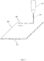
FIG. 2 illustrates a microperforated overlay for an acoustic structure in accordance with various embodiments; -
FIG. 3 illustrates an acoustic structure in accordance with various embodiments; and -
FIG. 4 illustrates a flowchart of a process for manufacturing an acoustic structure in accordance with various embodiments. - The detailed description of various embodiments herein makes reference to the accompanying drawings, which show various embodiments by way of illustration. While these various embodiments are described in sufficient detail to enable those skilled in the art to practice the inventions, it should be understood that other embodiments may be realized and that logical, chemical and mechanical changes may be made without departing from the scope of the inventions. Thus, the detailed description herein is presented for purposes of illustration only and not of limitation. For example, the steps recited in any of the method or process descriptions may be executed in any order and are not necessarily limited to the order presented. Furthermore, any reference to singular includes plural embodiments, and any reference to more than one component or step may include a singular embodiment or step. Also, any reference to attached, fixed, connected or the like may include permanent, removable, temporary, partial, full and/or any other possible attachment option. Additionally, any reference to without contact (or similar phrases) may also include reduced contact or minimal contact.
- In an acoustic panel made with a fiber reinforced composite top sheet, the top sheet is not very thermally conductive. Laser drilling perforations in such a top sheet causes heat input which due to the lack of thermal conductivity may result in localized heating of the substrate to a high temperature. The need to avoid localized heating to too high a temperature, which may damage the structure of a fiber reinforced composite top sheet, presents a practical limit to how quickly the laser drilling may occur. Through experimentation, the inventors have discovered and shown that the addition of nanomaterials can effectively improve the properties of a fiber reinforced composite top sheet to better permit laser drilling and permit faster drilling rates without thermal damage. Without limiting the invention to any particular theory of causation, it is believed that improved thermal conductivity through the addition of the nanomaterials may be a potential factor in the observed improvements, but other factors are likely also playing a role.
- Referring to
FIG. 1 , a perforatedtop sheet 100 is illustrated according to various embodiments. Perforatedtop sheet 100 may comprise a composite substrate.Perforated top sheet 100 may comprise a series ofcomposite plies 110.Composite plies 110 may comprise a polymeric material reinforced with fibers, such as carbon fibers.Composite plies 110 may provide strength to perforatedtop sheet 100.Perforated top sheet 100 may further comprise asurface film 120.Surface film 120 may comprise a polymeric material.Surface film 120 may comprise a smooth finish compared tocomposite plies 110.Surface film 120 may thus decrease friction between perforatedtop sheet 100 and a fluid moving relative to perforatedtop sheet 100.Surface film 120 may reduce friction of air moving acrosssurface film 120 in the context of, for example, an aircraft flying through air. - In various embodiments, at least one of
composite plies 110 and/orsurface film 120 may comprisenanomaterials 130. In various embodiments, thenanomaterials 130 may comprise at least one of carbon nanotubes, carbon nanofibers, and graphene nanoplatelets. Thenanomaterials 130 may have a higher thermal conductivity than the polymeric material in thecomposite plies 110 orsurface film 120. Thus, the inclusion of nanomaterials may increase the thermal conductivity of theperforated top sheet 100. -
Perforations 140 may be formed in perforatedtop sheet 100.Perforations 140 may be added for acoustic properties, such as to allow sound waves to pass into a honeycomb core. In various embodiments,perforations 140 may have a diameter D1 of between .040 inches - .060 inches (.10 cm - .15 cm) or between .020 inches - .080 inches (.051 cm - .20 cm).Perforations 140 may be formed by laser drilling.Laser drill 150 maydirect beam 155 at perforatedtop sheet 100 in order to formperforations 140. Alternatively, a plurality of laser beams may be used to formperforations 140. Laser drilling may, as a by-product, result in heat input to thetop sheet 100. The greater the drilling rate, the greater the potential rate of heat input. If the heat input rate is too high, thetop sheet 100 will locally heat up around the laser-drilled perforations and may cause damage. - The
nanomaterials 130 present in thesurface film 120 and/orcomposite plies 110 may increase the dissipation rate of the heat generated by the laser drilling due to the thermal conductivity of thenanomaterials 130. Thus, the rate of laser drilling may be increased without resulting in high local temperatures of the substrate or damaging theperforated top sheet 100 as compared to a perforated top sheet without nanomaterials. The faster perforation rate may dramatically decrease the costs associated with fabricating theperforated top sheet 100. - Referring to
FIG. 2 , amicroperforated film 200 is illustrated according to various embodiments.Microperforated film 200 may comprise a microperforated overlay film configured to be coupled to perforatedtop sheet 100 illustrated inFIG. 1 .Microperforated film 200 may comprisegraphene nanoplatelets 210. In various embodiments,microperforated film 200 may alternatively comprise other forms of nanomaterials such as carbon nanotubes and/or carbon nanofibers.Graphene nanoplatelets 210 may comprise short stacks of platelet-shaped graphene sheets. The graphene nanoplatelets 210 may have relatively high thermal conductivity compared to polymeric materials. In various embodiments,microperforated film 200 may comprise microperforations 220.Microperforations 220 may be added for acoustic properties, such as to allow sound waves to pass throughmicroperforated film 200 and perforatedtop sheet 100 into an acoustic panel.Microperforations 220 may be smaller thanperforations 140 in perforatedtop sheet 100, such as, for example, five times smaller thanperforations 140.Microperforations 220 may be substantially circular (of course, other shapes or profiles are possible) and may have a diameter D2 of about .001 inches (.0025 cm), or a diameter D2 of between .001 inches - .020 inches (.0025 cm - .051 cm), or between .0005 inches - .040 inches (.0020 cm - .10 cm). The smaller diameter may result in lower drag as compared to theperforations 140 in perforatedtop sheet 100. - In various embodiments,
microperforated film 200 may further comprise an adhesive.Microperforated film 200 may be submersed in an adhesive bath in order to coat thegraphene nanoplatelets 210 with the adhesive. In various embodiments, the adhesive may be a no-flow adhesive, such that the adhesive does not clogmicroperforations 220 during bonding ofmicroperforated film 200 to a substrate. - In various embodiments, microperforations 220 may be formed by laser drilling.
Laser drill 230 may directbeam 235 atmicroperforated film 200 in order to form microperforations 220. The graphene nanoplatelets 210 may increase the dissipation rate of the heat generated by the laser drilling due to the thermal conductivity of thegraphene nanoplatelets 210. Thus, the perforation rate may be faster without damaging themicroperforated film 200 as compared to a microperforated overlay without nanomaterials. The faster perforation rate may decrease costs associated with fabricating themicroperforated film 200. - Table 1 illustrates observed results of laser drilling microperforated films with varying numbers and diameters of microperforations. In each case, the sample microperforated film was a 6 inch by 6 inch (15 cm by 15 cm) nanoreinforced adhesive film with a thickness of less than .001 inch (.0025cm). The sample films were reinforced with carbon nanotubes. The film weight is measured in grams per square meter (gsm) before perforating, and the listed film weight does not include 2 gsm of adhesive which was present in the films; the hole diameter refers to the diameter of each microperforation in inches; the array size refers to the number of microperforations (e.g. 60 x 60 indicates 60 rows of 60 microperforations); the POA refers to the percentage of open area, which is the area of the microperforations divided by the area of the microperforated pattern (higher POAs indicate larger and/or more closely spaced microperforations); and the time indicates the time taken to laser drill the entire microperforated pattern. Each microperforation was drilled with a 30 Watt laser using a 2 pass trepan technique, wherein the laser drill followed a circumference of each microperforation two times to remove a disk corresponding to the microperforation.
Table 1 Film Weight Hole Diameter Array Size POA Time Sample 1 10 gsm .020" (0.51 cm) 60x60 21% 8 min Sample 2 10gsm .020" (0.51 cm) 60 x 60 10% 8:30 min Sample 3 10 gsm .005" (0.01 cm) 100 x 100 1% 22 min Sample 4 10 gsm .001" (0.0025 cm) 100 x 100 0.5% 22 min Sample 5 5 gsm .020" (0.51 cm) 60 x 60 21% 8:30 min Sample 6 5 gsm .020" (0.51 cm) 60 x 60 10% 8:30 min Sample 7 5 gsm .005" (0.01 cm) 100 x 100 1% 22 min Sample 8 5 gsm .001" (0.0025 cm) 100 x 100 0.5% 22 min - As shown in Table 1, microperforation patterns of 60 x 60 holes (3600 holes) were laser drilled in eight minutes and thirty seconds or less (7.5 holes/second), and perforation patterns of 100 x 100 holes (10,000 holes) were drilled in twenty-two minutes (7.6 holes/second), both without heat damage to the microperforated film. A speed limitation due to heat damage was not observed in any of the samples described in Table 1. In contrast, typical times to drill a similar 60 x 60 laser-drilled perforation pattern without heat damage in a polymeric film without nanomaterials may be greater than sixty minutes (1.0 holes/second). Thus, the carbon nanotubes allow for increased throughput and reduced costs of manufacturing microperforated overlays.
- Referring to
FIG. 3 , a perspective view of ahoneycomb structure 300 is illustrated according to various embodiments. Thehoneycomb structure 300 may comprise a plurality ofcells 310, positioned between a perforatedtop sheet 320 and aback skin 330. The bottom of thehoneycomb structure 300 may be closed by a generally rigid non-perforated plate referred to herein as theback skin 330. A perforatedtop sheet 320 havingperforations 325 may be coupled to the top of thehoneycomb structure 300. Additional layers may be formed on top of the perforatedtop sheet 320 for airflow and/or acoustic properties as desired. The perforatedtop sheet 320,cell 310, and backskin 330 combine to form acell 310 that becomes a resonating chamber and works to damp acoustic emissions, such as sound waves from an aircraft engine. Stated another way, one function of thehoneycomb structure 300 may be to attenuate sound waves, such as high frequency sound waves (for example, in the frequency range varying from 4000 Hz to 5000 Hz). - A
microperforated film 340 is illustrated coupled to perforatedtop sheet 320 onhoneycomb structure 300 according to various embodiments.Microperforated film 340 may comprise microperforations 345. In various embodiments, at least one ofmicroperforated film 340 and perforatedtop sheet 320 may comprise nanoparticles.Microperforated film 340 may comprise an adhesive which may bondmicroperforated film 340 to perforatedtop sheet 320.Microperforations 345 inmicroperforated film 340 may cause less drag thanperforations 325 in perforatedtop sheet 320, while still allowing for sound waves to pass intohoneycomb cells 310. The POA for the combination of perforatedtop sheet 320 andmicroperforated film 340 may be calculated by multiplying the POA of perforatedtop sheet 320 by the POA ofmicroperforated film 340. - In operation, acoustic treatment structures such as
honeycomb structure 300 are typically incorporated in the engine inlet, nacelle and exhaust structures of an aircraft engine. For instance, airflow surfaces over elements of an aircraft, such as airflow over perforatedtop sheet 320, may be perforated with thousands ofperforations 325 typically in the range of about 1 mm/0.040 inch in diameter. Conventionally, theperforations 325 are configured to attenuate the jet engine's noise by damping the energy response, directing the sound into thecell 310 of thehoneycomb structure 300 to allow reflected noise to cancel source noise. Optionally, thecell 310 of thehoneycomb structure 300 may comprise one or more septum caps configured for greater noise suppression and treatment of a wider range of attenuated frequencies. - Referring to
FIG. 4 , a flowchart of a process 400 for forming a substrate with perforations is illustrated. A first substrate comprising nanoparticles may be provided. The first substrate may be disposed proximate to a laser (step 410). In various embodiments, the first substrate may comprise at least one of a top sheet for an acoustic structure and an overlay for an acoustic structure. In various embodiments, the first substrate may comprise a composite ply and a surface film. The surface film may be disposed on the composite ply. The nanoparticles may comprise at least one of carbon nanotubes, carbon nanofibers, and graphene nanoplatelets. In various embodiments, an adhesive may be applied to the first substrate. - A laser may drill holes in the first substrate (step 420). In various embodiments, the laser may follow a 2 pass trepan pattern in drilling the holes. In various embodiments, the laser may drill the holes at a rate of at least 2 holes per second. In various embodiments, the laser may drill the holes at a rate of at least 7.5 holes per second. In various embodiments, the holes may comprise a diameter of between .001 inches - .040 inches (.0025 cm - .10 cm).
- In various embodiments, a second substrate comprising nanoparticles may be provided. The second substrate may be disposed proximate to the laser (step 430). In various embodiments, the second substrate may comprise at least one of a top sheet for an acoustic structure and an overlay film for an acoustic structure. In various embodiments, the first substrate may comprise an overlay film, and the second substrate may comprise a top sheet. The nanoparticles may comprise at least one of carbon nanotubes, carbon nanofibers, and graphene nanoplatelets.
- A laser may drill holes in the second substrate (step 440). In various embodiments, the holes in the second substrate may comprise a diameter of between .040 inches-.080 inches (.10 cm - .20 cm). In various embodiments, the second substrate may be overlayed on the first substrate, such that the holes in the second substrate overlap the holes in the first substrate (step 450). In various embodiments, the second substrate may be bonded to the first substrate. In various embodiments, the first substrate and/or second substrate may be coupled to a honeycomb core.
- Although described primarily with reference to a honeycomb structure and noise attenuation, the systems and methods described herein may be utilized in any instance where rapid laser drilling of a substrate is desired.
- In the detailed description herein, references to "one embodiment", "an embodiment", "various embodiments", etc., indicate that the embodiment described may include a particular feature, structure, or characteristic, but every embodiment may not necessarily include the particular feature, structure, or characteristic. Moreover, such phrases are not necessarily referring to the same embodiment. Further, when a particular feature, structure, or characteristic is described in connection with an embodiment, it is submitted that it is within the knowledge of one skilled in the art to affect such feature, structure, or characteristic in connection with other embodiments whether or not explicitly described. After reading the description, it will be apparent to one skilled in the relevant art(s) how to implement the disclosure in alternative embodiments.
- Benefits, other advantages, and solutions to problems have been described herein with regard to specific embodiments. Furthermore, the connecting lines shown in the various figures contained herein are intended to represent exemplary functional relationships and/or physical couplings between the various elements. It should be noted that many alternative or additional functional relationships or physical connections may be present in a practical system. However, the benefits, advantages, solutions to problems, and any elements that may cause any benefit, advantage, or solution to occur or become more pronounced are not to be construed as critical, required, or essential features or elements of the inventions. The scope of the inventions is accordingly to be limited by nothing other than the appended claims, in which reference to an element in the singular is not intended to mean "one and only one" unless explicitly so stated, but rather "one or more." Moreover, where a phrase similar to "at least one of A, B, or C" is used in the claims, it is intended that the phrase be interpreted to mean that A alone may be present in an embodiment, B alone may be present in an embodiment, C alone may be present in an embodiment, or that any combination of the elements A, B and C may be present in a single embodiment; for example, A and B, A and C, B and C, or A and B and C. Different cross-hatching is used throughout the figures to denote different parts but not necessarily to denote the same or different materials.
Claims (15)
- A method of manufacturing an acoustic structure (300) comprising:drilling a first plurality of holes (220;345) in an overlay film (200;340), wherein the overlay film (200;340) comprises nanoparticles (130);drilling a second plurality of holes (140;325) in a composite substrate (100;320); andcoupling the overlay film (200;340) to the composite substrate (100;320).
- The method of claim 1, wherein the composite substrate (100;320) comprises a composite ply (110) and a surface film (120).
- The method of claim 2, wherein the surface film (120) comprises nanoparticles (130).
- The method of claim 1, 2 or 3, wherein the composite substrate (100;320) comprises nanoparticles (130).
- The method of any preceding claim, wherein a diameter (D1) of the second plurality of holes (140;325) is at least five times greater than a diameter (D2) of the first plurality of holes (220;345).
- The method of any preceding claim, wherein the nanoparticles (130) comprise at least one of carbon nanotubes, carbon nanofibers, and graphene nanoplatelets (210).
- The method of any preceding claim, wherein the coupling the overlay film (200;340) to the composite substrate (100;320) is performed prior to the drilling the second holes (140;325).
- The method of any preceding claim, wherein the first plurality of holes (220;345) and the second plurality of holes (140;325) are drilled with a laser.
- A method of drilling holes (140;325) in a composite substrate (100;320) comprising:fabricating a composite substrate (100;320) comprising a fiber reinforced composite ply (110) and a surface film (120) comprising nanoparticles (130) disposed on the fiber reinforced composite ply (110); anddrilling holes (140;325) in the composite substrate (100;320).
- The method of claim 9, wherein the holes (140;325) are drilled with at least one of a drill bit and a laser beam.
- The method of claim 9 or 10, wherein the nanoparticles (130) comprise at least one of carbon nanotubes, carbon nanofibers, and graphene nanoplatelets (210).
- The method of claim 9, 10 or 11, wherein the holes (140;325) are drilled at a rate of at least 2 holes per second for every laser beam or drill bit.
- The method of any of claims 9 to 12, wherein the nanoparticles (130) are configured to dissipate heat generated by the drilling the holes (140;325).
- The method of any of claims 9 to 13, wherein the drilling the holes (140;325) comprises drilling the holes (140;325) with a plurality of laser beams or drill bits.
- The method of any of claims 9 to 14, wherein the composite ply (110) comprises nanoparticles (130).
Applications Claiming Priority (2)
| Application Number | Priority Date | Filing Date | Title |
|---|---|---|---|
| US14/261,154 US9463596B2 (en) | 2014-04-24 | 2014-04-24 | Systems and methods for perforating materials |
| EP15164241.0A EP2944415B1 (en) | 2014-04-24 | 2015-04-20 | Methods for perforating materials |
Related Parent Applications (2)
| Application Number | Title | Priority Date | Filing Date |
|---|---|---|---|
| EP15164241.0A Division EP2944415B1 (en) | 2014-04-24 | 2015-04-20 | Methods for perforating materials |
| EP15164241.0A Division-Into EP2944415B1 (en) | 2014-04-24 | 2015-04-20 | Methods for perforating materials |
Publications (2)
| Publication Number | Publication Date |
|---|---|
| EP3978185A2 true EP3978185A2 (en) | 2022-04-06 |
| EP3978185A3 EP3978185A3 (en) | 2022-06-08 |
Family
ID=52997302
Family Applications (2)
| Application Number | Title | Priority Date | Filing Date |
|---|---|---|---|
| EP15164241.0A Active EP2944415B1 (en) | 2014-04-24 | 2015-04-20 | Methods for perforating materials |
| EP21205373.0A Pending EP3978185A3 (en) | 2014-04-24 | 2015-04-20 | Methods for perforating materials |
Family Applications Before (1)
| Application Number | Title | Priority Date | Filing Date |
|---|---|---|---|
| EP15164241.0A Active EP2944415B1 (en) | 2014-04-24 | 2015-04-20 | Methods for perforating materials |
Country Status (2)
| Country | Link |
|---|---|
| US (2) | US9463596B2 (en) |
| EP (2) | EP2944415B1 (en) |
Families Citing this family (11)
| Publication number | Priority date | Publication date | Assignee | Title |
|---|---|---|---|---|
| US9463596B2 (en) | 2014-04-24 | 2016-10-11 | Rohr, Inc. | Systems and methods for perforating materials |
| US10000277B2 (en) * | 2014-10-16 | 2018-06-19 | Rohr, Inc. | Perforated surface for suction-type laminar flow control |
| US9447576B2 (en) * | 2015-01-09 | 2016-09-20 | Rohr, Inc. | Post bond perforation of a septum in an acoustic panel |
| GB201521075D0 (en) * | 2015-11-30 | 2016-01-13 | Short Brothers Plc | Methods, precursors and abrasive blasting masks for manufacturing noise attenuating devices |
| CN106270604A (en) * | 2016-08-23 | 2017-01-04 | 张家港华日法兰有限公司 | A kind of drilling method of flange |
| FR3069210B1 (en) * | 2017-07-24 | 2020-12-11 | Faurecia Automotive Ind | AUTOMOTIVE VEHICLE SOUNDPROOFING PART AND ASSOCIATED MANUFACTURING PROCESS |
| US11052490B2 (en) * | 2018-04-27 | 2021-07-06 | The Boeing Company | Inner barrel of an engine inlet with laser-machined acoustic perforations |
| US11433990B2 (en) | 2018-07-09 | 2022-09-06 | Rohr, Inc. | Active laminar flow control system with composite panel |
| US11524366B2 (en) * | 2018-07-26 | 2022-12-13 | Coherent Munich GmbH & Co. KG | Separation and release of laser-processed brittle material |
| CN110026693A (en) * | 2019-04-03 | 2019-07-19 | 大族激光科技产业集团股份有限公司 | Laser boring method, device, electronic device and computer readable storage medium |
| CN114289903B (en) * | 2022-01-11 | 2024-02-02 | 常州富烯科技股份有限公司 | Graphene film laser processing method and graphene film laser processing equipment |
Family Cites Families (10)
| Publication number | Priority date | Publication date | Assignee | Title |
|---|---|---|---|---|
| US4589190A (en) * | 1984-03-23 | 1986-05-20 | General Electric Company | Fabrication of drilled and diffused junction field-effect transistors |
| US4839497A (en) | 1987-09-03 | 1989-06-13 | Digital Equipment Corporation | Drilling apparatus and method |
| US5653836A (en) | 1995-07-28 | 1997-08-05 | Rohr, Inc. | Method of repairing sound attenuation structure used for aircraft applications |
| US6875951B2 (en) * | 2000-08-29 | 2005-04-05 | Mitsubishi Denki Kabushiki Kaisha | Laser machining device |
| FR2827205B1 (en) * | 2001-07-12 | 2003-12-05 | Airbus France | PROCESS FOR PRODUCING HOLES, PARTICULARLY MICROPROFORATIONS IN A COMPOSITE MATERIAL, DEVICE FOR IMPLEMENTING SAME AND ACOUSTIC SHOCKING LAYER CONSISTING OF SAID MATERIAL |
| TWI298007B (en) | 2006-04-03 | 2008-06-11 | Uniplus Electronics Co Ltd | Heat-dissipating accessory plate for high speed drilling |
| US7534648B2 (en) * | 2006-06-29 | 2009-05-19 | Intel Corporation | Aligned nanotube bearing composite material |
| US8068624B2 (en) * | 2008-04-28 | 2011-11-29 | Beijing Funate Innovation Technology Co., Ltd. | Thermoacoustic device |
| TWI417017B (en) | 2009-07-30 | 2013-11-21 | Unimicron Technology Corp | Base material of wiring board and method for drilling thereof |
| US9463596B2 (en) | 2014-04-24 | 2016-10-11 | Rohr, Inc. | Systems and methods for perforating materials |
-
2014
- 2014-04-24 US US14/261,154 patent/US9463596B2/en active Active
-
2015
- 2015-04-20 EP EP15164241.0A patent/EP2944415B1/en active Active
- 2015-04-20 EP EP21205373.0A patent/EP3978185A3/en active Pending
-
2016
- 2016-09-13 US US15/264,408 patent/US10052723B2/en active Active
Also Published As
| Publication number | Publication date |
|---|---|
| US9463596B2 (en) | 2016-10-11 |
| EP3978185A3 (en) | 2022-06-08 |
| EP2944415A3 (en) | 2016-05-18 |
| US20150306815A1 (en) | 2015-10-29 |
| US20170001265A1 (en) | 2017-01-05 |
| EP2944415B1 (en) | 2021-12-08 |
| US10052723B2 (en) | 2018-08-21 |
| EP2944415A2 (en) | 2015-11-18 |
Similar Documents
| Publication | Publication Date | Title |
|---|---|---|
| EP2944415B1 (en) | Methods for perforating materials | |
| EP2833356B1 (en) | Acoustic panel | |
| EP2472509B1 (en) | Septum cap for acoustic honeycomb | |
| CN101652809B (en) | Method for producing an acoustically resistive structure, resulting acoustically resistive structure and skin using one such structure | |
| US9938852B2 (en) | Noise attenuating lipskin assembly and methods of assembling the same | |
| EP2953130B1 (en) | Acoustically attenuating sandwich panel constructions | |
| US8863893B2 (en) | Engine inlet varying impedance acoustic liner section | |
| US4318453A (en) | Double layer attenuation panel | |
| CN104025187B (en) | Acoustic honeycomb with perforated septum caps | |
| US8607924B2 (en) | Anchoring of septums in acoustic honeycomb | |
| US4294329A (en) | Double layer attenuation panel with two layers of linear type material | |
| JP6781676B2 (en) | Molding sound insulation structure forming method | |
| US11072413B2 (en) | Virtual aerodynamic surface systems | |
| CN101689362A (en) | Panel for sound insulation treatment | |
| JP6510653B2 (en) | Soundproof structure | |
| EP3042755B1 (en) | Perforation of a septum in a prefabicated acoustic panel | |
| CN101903160B (en) | Method for joining cellular acoustic panels | |
| CN102143889A (en) | Method for making an acoustic panel for the air intake lip of a nacelle | |
| CN102271904A (en) | Improved composite materials | |
| CN211975529U (en) | Intermediate assembly for manufacturing acoustic-lined perforated panels | |
| US12110126B2 (en) | Method for manufacturing a sound-absorbing sandwich panel for reducing noise of an aircraft engine | |
| CN103827958A (en) | Intermediate acoustic skin and the implementation thereof | |
| GB2059341A (en) | Double layer attenuation panel | |
| CN101625856A (en) | Multifrequency sound absorption foam faced material and preparation method thereof | |
| US20250319685A1 (en) | Structural element provided with applied inserts for a composite acoustic structure, and associated manufacturing method |
Legal Events
| Date | Code | Title | Description |
|---|---|---|---|
| PUAI | Public reference made under article 153(3) epc to a published international application that has entered the european phase |
Free format text: ORIGINAL CODE: 0009012 |
|
| STAA | Information on the status of an ep patent application or granted ep patent |
Free format text: STATUS: THE APPLICATION HAS BEEN PUBLISHED |
|
| AC | Divisional application: reference to earlier application |
Ref document number: 2944415 Country of ref document: EP Kind code of ref document: P |
|
| AK | Designated contracting states |
Kind code of ref document: A2 Designated state(s): AL AT BE BG CH CY CZ DE DK EE ES FI FR GB GR HR HU IE IS IT LI LT LU LV MC MK MT NL NO PL PT RO RS SE SI SK SM TR |
|
| PUAL | Search report despatched |
Free format text: ORIGINAL CODE: 0009013 |
|
| AK | Designated contracting states |
Kind code of ref document: A3 Designated state(s): AL AT BE BG CH CY CZ DE DK EE ES FI FR GB GR HR HU IE IS IT LI LT LU LV MC MK MT NL NO PL PT RO RS SE SI SK SM TR |
|
| RIC1 | Information provided on ipc code assigned before grant |
Ipc: E04B 1/86 20060101ALI20220504BHEP Ipc: B23K 26/402 20140101ALI20220504BHEP Ipc: B23K 26/70 20140101ALI20220504BHEP Ipc: B23K 26/40 20140101ALI20220504BHEP Ipc: B23K 26/382 20140101AFI20220504BHEP |
|
| STAA | Information on the status of an ep patent application or granted ep patent |
Free format text: STATUS: REQUEST FOR EXAMINATION WAS MADE |
|
| 17P | Request for examination filed |
Effective date: 20221208 |
|
| RBV | Designated contracting states (corrected) |
Designated state(s): AL AT BE BG CH CY CZ DE DK EE ES FI FR GB GR HR HU IE IS IT LI LT LU LV MC MK MT NL NO PL PT RO RS SE SI SK SM TR |
|
| STAA | Information on the status of an ep patent application or granted ep patent |
Free format text: STATUS: EXAMINATION IS IN PROGRESS |
|
| 17Q | First examination report despatched |
Effective date: 20250528 |