EP3978168A1 - Coated tool and cutting tool - Google Patents
Coated tool and cutting tool Download PDFInfo
- Publication number
- EP3978168A1 EP3978168A1 EP20813333.0A EP20813333A EP3978168A1 EP 3978168 A1 EP3978168 A1 EP 3978168A1 EP 20813333 A EP20813333 A EP 20813333A EP 3978168 A1 EP3978168 A1 EP 3978168A1
- Authority
- EP
- European Patent Office
- Prior art keywords
- layer
- content
- atomic
- coated tool
- gas
- Prior art date
- Legal status (The legal status is an assumption and is not a legal conclusion. Google has not performed a legal analysis and makes no representation as to the accuracy of the status listed.)
- Pending
Links
Images



Classifications
-
- B—PERFORMING OPERATIONS; TRANSPORTING
- B23—MACHINE TOOLS; METAL-WORKING NOT OTHERWISE PROVIDED FOR
- B23B—TURNING; BORING
- B23B27/00—Tools for turning or boring machines; Tools of a similar kind in general; Accessories therefor
- B23B27/14—Cutting tools of which the bits or tips or cutting inserts are of special material
- B23B27/148—Composition of the cutting inserts
-
- B—PERFORMING OPERATIONS; TRANSPORTING
- B23—MACHINE TOOLS; METAL-WORKING NOT OTHERWISE PROVIDED FOR
- B23B—TURNING; BORING
- B23B27/00—Tools for turning or boring machines; Tools of a similar kind in general; Accessories therefor
- B23B27/14—Cutting tools of which the bits or tips or cutting inserts are of special material
-
- B—PERFORMING OPERATIONS; TRANSPORTING
- B23—MACHINE TOOLS; METAL-WORKING NOT OTHERWISE PROVIDED FOR
- B23C—MILLING
- B23C5/00—Milling-cutters
- B23C5/16—Milling-cutters characterised by physical features other than shape
-
- C—CHEMISTRY; METALLURGY
- C23—COATING METALLIC MATERIAL; COATING MATERIAL WITH METALLIC MATERIAL; CHEMICAL SURFACE TREATMENT; DIFFUSION TREATMENT OF METALLIC MATERIAL; COATING BY VACUUM EVAPORATION, BY SPUTTERING, BY ION IMPLANTATION OR BY CHEMICAL VAPOUR DEPOSITION, IN GENERAL; INHIBITING CORROSION OF METALLIC MATERIAL OR INCRUSTATION IN GENERAL
- C23C—COATING METALLIC MATERIAL; COATING MATERIAL WITH METALLIC MATERIAL; SURFACE TREATMENT OF METALLIC MATERIAL BY DIFFUSION INTO THE SURFACE, BY CHEMICAL CONVERSION OR SUBSTITUTION; COATING BY VACUUM EVAPORATION, BY SPUTTERING, BY ION IMPLANTATION OR BY CHEMICAL VAPOUR DEPOSITION, IN GENERAL
- C23C16/00—Chemical coating by decomposition of gaseous compounds, without leaving reaction products of surface material in the coating, i.e. chemical vapour deposition [CVD] processes
- C23C16/22—Chemical coating by decomposition of gaseous compounds, without leaving reaction products of surface material in the coating, i.e. chemical vapour deposition [CVD] processes characterised by the deposition of inorganic material, other than metallic material
- C23C16/30—Deposition of compounds, mixtures or solid solutions, e.g. borides, carbides, nitrides
- C23C16/301—AIII BV compounds, where A is Al, Ga, In or Tl and B is N, P, As, Sb or Bi
- C23C16/303—Nitrides
-
- C—CHEMISTRY; METALLURGY
- C23—COATING METALLIC MATERIAL; COATING MATERIAL WITH METALLIC MATERIAL; CHEMICAL SURFACE TREATMENT; DIFFUSION TREATMENT OF METALLIC MATERIAL; COATING BY VACUUM EVAPORATION, BY SPUTTERING, BY ION IMPLANTATION OR BY CHEMICAL VAPOUR DEPOSITION, IN GENERAL; INHIBITING CORROSION OF METALLIC MATERIAL OR INCRUSTATION IN GENERAL
- C23C—COATING METALLIC MATERIAL; COATING MATERIAL WITH METALLIC MATERIAL; SURFACE TREATMENT OF METALLIC MATERIAL BY DIFFUSION INTO THE SURFACE, BY CHEMICAL CONVERSION OR SUBSTITUTION; COATING BY VACUUM EVAPORATION, BY SPUTTERING, BY ION IMPLANTATION OR BY CHEMICAL VAPOUR DEPOSITION, IN GENERAL
- C23C16/00—Chemical coating by decomposition of gaseous compounds, without leaving reaction products of surface material in the coating, i.e. chemical vapour deposition [CVD] processes
- C23C16/22—Chemical coating by decomposition of gaseous compounds, without leaving reaction products of surface material in the coating, i.e. chemical vapour deposition [CVD] processes characterised by the deposition of inorganic material, other than metallic material
- C23C16/30—Deposition of compounds, mixtures or solid solutions, e.g. borides, carbides, nitrides
- C23C16/34—Nitrides
-
- C—CHEMISTRY; METALLURGY
- C23—COATING METALLIC MATERIAL; COATING MATERIAL WITH METALLIC MATERIAL; CHEMICAL SURFACE TREATMENT; DIFFUSION TREATMENT OF METALLIC MATERIAL; COATING BY VACUUM EVAPORATION, BY SPUTTERING, BY ION IMPLANTATION OR BY CHEMICAL VAPOUR DEPOSITION, IN GENERAL; INHIBITING CORROSION OF METALLIC MATERIAL OR INCRUSTATION IN GENERAL
- C23C—COATING METALLIC MATERIAL; COATING MATERIAL WITH METALLIC MATERIAL; SURFACE TREATMENT OF METALLIC MATERIAL BY DIFFUSION INTO THE SURFACE, BY CHEMICAL CONVERSION OR SUBSTITUTION; COATING BY VACUUM EVAPORATION, BY SPUTTERING, BY ION IMPLANTATION OR BY CHEMICAL VAPOUR DEPOSITION, IN GENERAL
- C23C16/00—Chemical coating by decomposition of gaseous compounds, without leaving reaction products of surface material in the coating, i.e. chemical vapour deposition [CVD] processes
- C23C16/22—Chemical coating by decomposition of gaseous compounds, without leaving reaction products of surface material in the coating, i.e. chemical vapour deposition [CVD] processes characterised by the deposition of inorganic material, other than metallic material
- C23C16/30—Deposition of compounds, mixtures or solid solutions, e.g. borides, carbides, nitrides
- C23C16/36—Carbonitrides
-
- C—CHEMISTRY; METALLURGY
- C23—COATING METALLIC MATERIAL; COATING MATERIAL WITH METALLIC MATERIAL; CHEMICAL SURFACE TREATMENT; DIFFUSION TREATMENT OF METALLIC MATERIAL; COATING BY VACUUM EVAPORATION, BY SPUTTERING, BY ION IMPLANTATION OR BY CHEMICAL VAPOUR DEPOSITION, IN GENERAL; INHIBITING CORROSION OF METALLIC MATERIAL OR INCRUSTATION IN GENERAL
- C23C—COATING METALLIC MATERIAL; COATING MATERIAL WITH METALLIC MATERIAL; SURFACE TREATMENT OF METALLIC MATERIAL BY DIFFUSION INTO THE SURFACE, BY CHEMICAL CONVERSION OR SUBSTITUTION; COATING BY VACUUM EVAPORATION, BY SPUTTERING, BY ION IMPLANTATION OR BY CHEMICAL VAPOUR DEPOSITION, IN GENERAL
- C23C16/00—Chemical coating by decomposition of gaseous compounds, without leaving reaction products of surface material in the coating, i.e. chemical vapour deposition [CVD] processes
- C23C16/22—Chemical coating by decomposition of gaseous compounds, without leaving reaction products of surface material in the coating, i.e. chemical vapour deposition [CVD] processes characterised by the deposition of inorganic material, other than metallic material
- C23C16/30—Deposition of compounds, mixtures or solid solutions, e.g. borides, carbides, nitrides
- C23C16/40—Oxides
- C23C16/403—Oxides of aluminium, magnesium or beryllium
-
- C—CHEMISTRY; METALLURGY
- C23—COATING METALLIC MATERIAL; COATING MATERIAL WITH METALLIC MATERIAL; CHEMICAL SURFACE TREATMENT; DIFFUSION TREATMENT OF METALLIC MATERIAL; COATING BY VACUUM EVAPORATION, BY SPUTTERING, BY ION IMPLANTATION OR BY CHEMICAL VAPOUR DEPOSITION, IN GENERAL; INHIBITING CORROSION OF METALLIC MATERIAL OR INCRUSTATION IN GENERAL
- C23C—COATING METALLIC MATERIAL; COATING MATERIAL WITH METALLIC MATERIAL; SURFACE TREATMENT OF METALLIC MATERIAL BY DIFFUSION INTO THE SURFACE, BY CHEMICAL CONVERSION OR SUBSTITUTION; COATING BY VACUUM EVAPORATION, BY SPUTTERING, BY ION IMPLANTATION OR BY CHEMICAL VAPOUR DEPOSITION, IN GENERAL
- C23C28/00—Coating for obtaining at least two superposed coatings either by methods not provided for in a single one of groups C23C2/00 - C23C26/00 or by combinations of methods provided for in subclasses C23C and C25C or C25D
- C23C28/04—Coating for obtaining at least two superposed coatings either by methods not provided for in a single one of groups C23C2/00 - C23C26/00 or by combinations of methods provided for in subclasses C23C and C25C or C25D only coatings of inorganic non-metallic material
-
- C—CHEMISTRY; METALLURGY
- C23—COATING METALLIC MATERIAL; COATING MATERIAL WITH METALLIC MATERIAL; CHEMICAL SURFACE TREATMENT; DIFFUSION TREATMENT OF METALLIC MATERIAL; COATING BY VACUUM EVAPORATION, BY SPUTTERING, BY ION IMPLANTATION OR BY CHEMICAL VAPOUR DEPOSITION, IN GENERAL; INHIBITING CORROSION OF METALLIC MATERIAL OR INCRUSTATION IN GENERAL
- C23C—COATING METALLIC MATERIAL; COATING MATERIAL WITH METALLIC MATERIAL; SURFACE TREATMENT OF METALLIC MATERIAL BY DIFFUSION INTO THE SURFACE, BY CHEMICAL CONVERSION OR SUBSTITUTION; COATING BY VACUUM EVAPORATION, BY SPUTTERING, BY ION IMPLANTATION OR BY CHEMICAL VAPOUR DEPOSITION, IN GENERAL
- C23C28/00—Coating for obtaining at least two superposed coatings either by methods not provided for in a single one of groups C23C2/00 - C23C26/00 or by combinations of methods provided for in subclasses C23C and C25C or C25D
- C23C28/04—Coating for obtaining at least two superposed coatings either by methods not provided for in a single one of groups C23C2/00 - C23C26/00 or by combinations of methods provided for in subclasses C23C and C25C or C25D only coatings of inorganic non-metallic material
- C23C28/042—Coating for obtaining at least two superposed coatings either by methods not provided for in a single one of groups C23C2/00 - C23C26/00 or by combinations of methods provided for in subclasses C23C and C25C or C25D only coatings of inorganic non-metallic material including a refractory ceramic layer, e.g. refractory metal oxides, ZrO2, rare earth oxides
-
- C—CHEMISTRY; METALLURGY
- C23—COATING METALLIC MATERIAL; COATING MATERIAL WITH METALLIC MATERIAL; CHEMICAL SURFACE TREATMENT; DIFFUSION TREATMENT OF METALLIC MATERIAL; COATING BY VACUUM EVAPORATION, BY SPUTTERING, BY ION IMPLANTATION OR BY CHEMICAL VAPOUR DEPOSITION, IN GENERAL; INHIBITING CORROSION OF METALLIC MATERIAL OR INCRUSTATION IN GENERAL
- C23C—COATING METALLIC MATERIAL; COATING MATERIAL WITH METALLIC MATERIAL; SURFACE TREATMENT OF METALLIC MATERIAL BY DIFFUSION INTO THE SURFACE, BY CHEMICAL CONVERSION OR SUBSTITUTION; COATING BY VACUUM EVAPORATION, BY SPUTTERING, BY ION IMPLANTATION OR BY CHEMICAL VAPOUR DEPOSITION, IN GENERAL
- C23C28/00—Coating for obtaining at least two superposed coatings either by methods not provided for in a single one of groups C23C2/00 - C23C26/00 or by combinations of methods provided for in subclasses C23C and C25C or C25D
- C23C28/04—Coating for obtaining at least two superposed coatings either by methods not provided for in a single one of groups C23C2/00 - C23C26/00 or by combinations of methods provided for in subclasses C23C and C25C or C25D only coatings of inorganic non-metallic material
- C23C28/044—Coating for obtaining at least two superposed coatings either by methods not provided for in a single one of groups C23C2/00 - C23C26/00 or by combinations of methods provided for in subclasses C23C and C25C or C25D only coatings of inorganic non-metallic material coatings specially adapted for cutting tools or wear applications
-
- C—CHEMISTRY; METALLURGY
- C23—COATING METALLIC MATERIAL; COATING MATERIAL WITH METALLIC MATERIAL; CHEMICAL SURFACE TREATMENT; DIFFUSION TREATMENT OF METALLIC MATERIAL; COATING BY VACUUM EVAPORATION, BY SPUTTERING, BY ION IMPLANTATION OR BY CHEMICAL VAPOUR DEPOSITION, IN GENERAL; INHIBITING CORROSION OF METALLIC MATERIAL OR INCRUSTATION IN GENERAL
- C23C—COATING METALLIC MATERIAL; COATING MATERIAL WITH METALLIC MATERIAL; SURFACE TREATMENT OF METALLIC MATERIAL BY DIFFUSION INTO THE SURFACE, BY CHEMICAL CONVERSION OR SUBSTITUTION; COATING BY VACUUM EVAPORATION, BY SPUTTERING, BY ION IMPLANTATION OR BY CHEMICAL VAPOUR DEPOSITION, IN GENERAL
- C23C30/00—Coating with metallic material characterised only by the composition of the metallic material, i.e. not characterised by the coating process
- C23C30/005—Coating with metallic material characterised only by the composition of the metallic material, i.e. not characterised by the coating process on hard metal substrates
Definitions
- the present disclosure relates to a coated tool and a cutting tool.
- Patent Document 1 discusses that high-speed machining parts having high wear resistance during high-speed machining are obtainable by ion implantation of halogen element and the like into a surface of a cutting tool.
- machining conditions of 150 m/min or more needs to be satisfied to ensure high wear resistance of the high-speed machining parts after subjected to the ion implantation, and wear resistance may be deteriorated at speeds lower than that.
- an apparatus and the step for the ion implantation into the surface of the cutting tool are necessary for carrying out the invention disclosed in Patent Document 1, thus leading to high costs for the cutting tool.
- a chlorine concentration is high on a side of the surface of the coating film, and the chlorine concentration is low on a side of a base of the coating layer. This can cause the problem that it is difficult to obtain sufficient effect on the side of the base of the coating film.
- Patent Document 2 discusses a coated tool with a coating layer, in which the coating film may include chlorine derived from a raw material gas during deposition even if including no ion implantation.
- Paragraph 0096 in Patent Document 2 says that residual chlorine correlates to film quality of a hard coating film and the film quality becomes better with decreasing the residual chlorine.
- Patent Document 3 discusses a cutting tool in which an outermost surface layer of a coating layer has a lower chlorine content than a Ti (C x1 N y1 O z1 ) layer located closer to a base than the outermost surface layer.
- a coated tool and a cutting tool are provided which are excellent in fracture resistance.
- a coated tool of the present disclosure includes a base and a coating layer located on the base.
- the coating layer includes, in order from a side of the base, a first layer including TiCN, a second layer including Al 2 O 3 , and a third layer including at least one of TiN and TiCN.
- a Cl content included in the first layer is a first Cl content
- a Cl content included in the second layer is a second Cl content
- a Cl content included in the third layer is a third Cl content.
- Each of the first Cl content and the third Cl content is larger than the second Cl content.
- the first Cl content is more than 0.2 atomic % and not more than 2 atomic %.
- the third Cl content is more than 0.2 atomic % and not more than 2 atomic %.
- a cutting tool of the present disclosure includes a holder which has a length from a first end to a second end and includes a pocket on a side of the first end, and the coated tool located in the pocket.
- Coated tools of the present disclosure are described in detail below.
- the drawings referred to in the following illustrate, in simplified form, only main members necessary for describing the embodiments.
- the coated tools of the present disclosure may include any arbitrary structural member not illustrated in the drawings referred to.
- Dimensions of the members in each of the drawings faithfully represent neither dimensions of actual structural members nor dimensional ratios of these members. These points are also true for cutting tools described later.
- the coated tool 1 of the present disclosure has a quadrangular plate shape, and includes a first surface 3 having a quadrangular shape (an upper surface in FIG. 1 ), a second surface 5 (a lateral surface in FIG. 1 ), and a cutting edge 7 located on at least a part of a ridgeline where the first surface 3 intersects with the second surface 5.
- the first surface 3 is a so-called rake surface.
- the second surface is a so-called flank surface.
- the coating tool 1 is not limited thereto.
- only one side of the first surface 3 having the quadrangular shape may include the cutting edge 7, or alternatively, the first surface 3 may partially include the cutting edge 7.
- a length of one side of the first surface 3 may be 3-20 mm.
- a height from the first surface 3 to a third surface 8 located on a side opposite to the first surface 3 may be approximately 5-20 mm.
- the coated tool 1 of the present disclosure includes a base 9 and a coating layer 11 to cover a surface of the base 9 as illustrated in FIG. 2 .
- the base 9 may be cemented carbide, cermet, cBN, ceramics, or the like.
- the coating layer 11 may cover the whole or a part of the surface of the base 9. If the coating layer 11 covers the part of the base 9, it can be rephrased that the coating layer 11 is located on at least the part of the base 9.
- the coating layer 11 in the coated tool 1 of the present disclosure is located on the base 9 as illustrated in FIG. 2 .
- the coating layer 11 includes, in order from a side of the base 9, a first layer 11a including TiCN, a second layer 11b including Al 2 O 3 , and a third layer 11c including at least one of TiN and TiCN.
- FIG. 2 illustrates an embodiment that the first layer 11a is located on the surface of the base 9.
- a TiN layer (not illustrated) may be located on the surface of the base 9.
- a different layer may be located between the first layer 11a and the second layer 11b.
- a different layer may be located between the second layer 11b and the third layer 11c.
- Both the first layer 11a and the third layer 11c include Cl.
- Including Cl denotes that Cl is detectable upon measurement of a cross section of the coating layer 11 by using a WDS (Wavelength Dispersive x-ray Spectroscopy).
- a Cl content (atomic %) included in the first layer 11a is a first Cl content
- a Cl content (atomic %) included in the second layer 11b is a second Cl content
- a Cl content (atomic %) included in the third layer 11c is a third Cl content.
- Each of the first Cl content and the third Cl content is larger than the second C content in the coated tool 1 of the present disclosure.
- the Cl content included in each of the first layer 11a and the third layer 11c is larger than the Cl content included in the second layer 11b.
- the Cl content of the second layer 11b may be a detection limit or less.
- the first Cl content is more than 0.2 atomic % and not more than 2 atomic %.
- the second Cl content is more than 0.2 atomic % and not more than 2 atomic %.
- the first layer 11a, the second layer 11b and the third layer 11c may be individually a single layer or a laminate of a plurality of layers.
- TiCN in the first layer 11a denotes one which includes Ti, C and N. If including C and N, a ratio of C and N may not be 1:1.
- the second layer 11b is a layer including Al 2 O 3 .
- Al 2 O 3 may be ⁇ -Al 2 O 3 or ⁇ -Al 2 O 3 .
- the third layer 11c may include both TiN and TiCN, or may include one of TiN and TiCN.
- TiCN may include C and N, and a ratio of C and N may not be 1:1.
- a thickness of the first layer 11a may be 5-20 ⁇ m.
- a thickness of the second layer 11b may be 2-12 ⁇ m.
- a thickness of the third layer 11c may be 0.5-3 ⁇ m.
- a thickness of the coating layer 11 may be, for example, 5-30 pm.
- the thickness of the coating layer 11 may be kept constant or may be different depending on location.
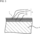
- FIG. 3 illustrates an embodiment that the third layer 11c is a multilayer.
- the third layer 11c includes a primary third layer 11c1 located closer to the base 9, and a secondary third layer 11c2 located on the primary third layer 11c1.
- Specific embodiments include one in which the primary third layer 11c1 includes TiCN and the secondary third layer 11c2 includes TiN.
- the primary third layer 11c1 may include TiN
- the secondary third layer 11c2 may include TiCN.
- the third layer 11c is formed by the plurality of layers, there are advantages that color control is performable arbitrarily and a part of the third layer 11c being exposed is easily distinguishable.
- the first layer 11a may also be a multilayer, and may include for example, a primary first layer (not illustrated) located closer to the base 9, and a secondary first layer located on the primary first layer (not illustrated) .
- the primary first layer may be an MT-TiCN layer.
- the secondary first layer may be an HT-TiCN layer.
- the second layer 11b may also be a multilayer, and may include, for example, a primary second layer (not illustrated) located closer to the base 9, and a secondary second layer (not illustrated) located on the primary second layer.
- the primary second layer and the secondary second layer may include ⁇ -Al 2 O 3 .
- the primary second layer and the secondary second layer may include ⁇ -Al 2 O 3 .
- the primary second layer and the secondary second layer may be different in ⁇ -Al 2 O 3 content.
- a Cl content in individual layers may be measured in a cross section of the coating layer 11 by using, for example, a wavelength-dispersive EPMA (JXA-8530F) manufactured by NIHON DENSHI.
- JXA-8530F wavelength-dispersive EPMA
- the coated tool 1 of the present disclosure is excellent in fracture resistance because of the above configuration.
- the coated tool 1 also has enhanced wear resistance both in low-speed machining at a machining speed of lower than 150 m/min and in high-speed machining at a machining speed of 150 m/min or higher.
- the first Cl content of the coated tool 1 of the present disclosure may be 0.7 atomic % or less. This configuration leads to an excellent balance between wear resistance and fracture resistance.
- the first Cl content of the coated tool 1 of the present disclosure may be more than 0.7 atomic %. With this configuration, the coated tool 1 is particularly excellent in fracture resistance.
- the third Cl content of the coated tool 1 of the present disclosure may be 0.7 atomic % or less. This configuration leads to an excellent balance between wear resistance and fracture resistance.
- the third Cl content of the coated tool 1 of the present disclosure may be more than 0.7 atomic %. With this configuration, the coated tool 1 is particularly excellent in fracture resistance.
- the third Cl content of the coated tool 1 of the present disclosure may be 0.9 atomic % or more. With this configuration, the coated tool 1 is further excellent in fracture resistance.
- the third Cl content may be larger than the first Cl content in the coated tool 1 of the present disclosure. This configuration leads to excellent fracture resistance.
- the cutting tool 101 of the present disclosure is, for example, a bar-shaped body extended from a first end (an upper end in FIG. 4 ) toward a second end (a lower end in FIG. 4 ).
- the cutting tool 101 includes a holder 105 having a length from the first end (front end) to the second end and including a pocket 103 located on a side of the first end, and the coated tool 1 located in the pocket 103.
- the cutting tool 101 includes the coated tool 1 excellent in fracture resistance, and is therefore capable of carrying out a stable cutting process for a long period of time.
- the pocket 103 is a part that permits attachment of the coated tool 1.
- the pocket 103 includes a seating surface parallel to a lower surface of the holder 105, and a constraining lateral surface vertical or inclined relative to the seating surface.
- the pocket 103 opens into a side of the first end of the holder 105.
- the coated tool 1 is located in the pocket 103.
- a lower surface of the coated tool 1 may be in a direct contact with the pocket 103.
- a sheet (not illustrated) may be held between the coated tool 1 and the pocket 103.
- the coated tool 1 is attached to the holder 105 so that at least a part of a ridgeline where the first surface 3 serving as a rake surface intersects with the second surface 5 serving as a flank surface, which is usable as the cutting edge 7, is protruded outward from the holder 105.
- the coated tool 1 is attached to the holder 105 with a screw 107 in the present embodiment.
- the coated tool 1 is attached to the holder 105 in such a manner that screw parts are engaged with each other by inserting the screw 107 into the through hole 17 of the coated tool 1, and by inserting a front end of the screw 107 into a screw hole (not illustrated) formed in the pocket 103.
- steel and cast iron are usable as a material of the holder 105.
- highly rigid steel may be used.
- the present embodiment illustrates and describes the cutting tool 101 for use in the so-called turning process.
- the turning process include inner diameter processing, outer diameter processing and grooving process.
- the cutting tool is not limited to one which is used for the turning process.
- the coated tools 1 of the above embodiments may be used for cutting tools used in a milling process.
- a method for manufacturing a coated tool in the present disclosure is described below. Firstly, a base having a predetermined shape is prepared. Cemented carbide including WC, cermet including TiCN, boron nitride and silicon nitride are usable for the base.
- a first layer, a second layer and a third layer are deposited on a surface of the base. These layers may be deposited by CVD method.
- Suitable deposition conditions for depositing the first layer on the base are a deposition temperature of 600-940 °C and a pressure of 5-25 kPa.
- the deposition is carried out by passing through a mixed gas composed of 10-20 vol% of titanium tetrachloride (TiCl 4 ) gas, 1-50 vol% of nitrogen (N 2 ) gas, 0.1-3.0 vol% of acetonitrile (CH 3 CN) gas, 1.0-15.0 vol% of hydrogen chloride (HCl) gas, and the rest, namely, hydrogen (H 2 ) gas.
- TiCl 4 titanium tetrachloride
- the first Cl content increases with increasing a proportion of the titanium tetrachloride (TiCl 4 ) gas included in a deposition gas.
- the first Cl content increases with decreasing the deposition temperature.
- the acetonitrile (CH 3 CN) gas may be changed to methane (CH 4 ) gas, or a mixed gas of both may be passed through.
- a film of two or more layers may be deposited to control the structure of the first layer.
- a deposition temperature is 700-1010 °C and a pressure is 5-10 kPa.
- the deposition is carried out by passing through a mixed gas composed of 0.5-20.0 vol% of aluminum trichloride (AlCl 3 ) gas, 0.5-5.0 vol% of hydrogen chloride (HCl) gas, 0.5-5.0 vol% of carbon dioxide (CO 2 ) gas, 0-0.5 vol% of hydrogen sulfide (H 2 S) gas, and the rest, namely, hydrogen (H 2 ) gas.
- AlCl 3 aluminum trichloride
- the second Cl content may be smaller than each of the first Cl content and the third Cl content, and may be controlled suitably depending on the first Cl content and the third Cl content.
- the third layer may include at least one of TiN and TiCN. An embodiment that the third layer includes TiN is first described, and an embodiment that the third layer includes TiCN is then described.
- the third layer including TiN is deposited at a deposition temperature of 600-940°C and a pressure of 8-50 kPa by passing through a mixed gas composed of 10-20 vol% of titanium tetrachloride (TiCl 4 ) gas, 10-50 vol% of nitrogen (N 2 ) gas, 1.0-15.0 vol% of hydrogen chloride (HCl) gas content, and the rest, namely, hydrogen (H 2 ) gas.
- TiCl 4 titanium tetrachloride
- HCl hydrogen chloride
- the third layer including TiCN is deposited at a deposition temperature of 600-940°C and a pressure of 5-25 kPa by passing through a mixed gas composed of 10-20 vol% of titanium tetrachloride (TiCl 4 ) gas, 1-50 vol% of nitrogen (N 2 ) gas, 0.1-6.0 vol% of acetonitrile (CH 3 CN) gas, 1.0-15.0 vol% of hydrogen chloride (HCl) gas, and the rest, namely, hydrogen (H 2 ) gas.
- a control of titanium tetrachloride (TiCl 4 ) gas makes it possible to control the third Cl content.
- An inclination of chlorine concentration in the coating layer which may occur in ion implantation, can be reduced by manufacturing a coating film including a predetermined amount of chlorine under the above control of the deposition conditions.
- a coated tool was manufactured by deposing a coating layer having a structure presented in Table 2 on a surface of a base composed of cemented carbide in the shape of CNMG120408PG under conditions presented in Table 1.
- a first layer TiCN film was deposited at a deposition temperature of 750°C and a pressure of 9 kPa.
- a second layer was deposited at a deposition temperature of 980 °C and a pressure of 9 kPa.
- Both TiN and TiCN films of a third layer were deposited at a deposition temperature of 850°C and a pressure of 12 kPa.
- a cross section of each of manufactured coated tools was subjected to mirror polishing, and a Cl content of each of the layers was measured with a wavelength dispersive type EPMA (JXA-8530F) manufactured by NIHON DENSHI. Measured values are presented in Table 2.
- the first layers in individual samples have the same thickness. This is also true for the second layers and the third layers in the individual samples. Specifically, the thickness of the first layer is 8 ⁇ m. The thickness of the second layer is 6 ⁇ m. The thickness of the third layer is 1.5 ⁇ m.
- a TiN layer having a thickness of 1 ⁇ m was disposed between a base and the first layer.
- the TiN layer was deposited at a deposition temperature of 750°C and a pressure of 9 kPa by passing through a mixed gas composed of 8 vol% of titanium tetrachloride (TiCl 4 ) gas, 10 vol% of nitrogen (N 2 ) gas, and the rest, namely, hydrogen (H 2 ) gas.
- the (Ti, Al) CNO layer was firstly deposited under deposition conditions for generating TiCNO.
- the layer is deposited at a deposition temperature of 850 °C and a pressure of 12 kPa by passing through a mixed gas composed of 6 vol% of titanium tetrachloride (TiCl 4 ) gas, 8 vol% of nitrogen (N 2 ) gas, 2 vol% of methane (CH 4 ) gas or acetonitrile (CH 3 CN) gas, 0.6 vol% of carbon monoxide (CO) gas, and the rest, namely, hydrogen (H 2 ) gas.
- a mixed gas composed of 6 vol% of titanium tetrachloride (TiCl 4 ) gas, 8 vol% of nitrogen (N 2 ) gas, 2 vol% of methane (CH 4 ) gas or acetonitrile (CH 3 CN) gas, 0.6 vol% of
- a cutting test was conducted using the obtained coated tools under the following machining conditions.
- the cutting test was conducted by using the first surface of the coated tool as a rake surface.
- the cutting test is a so-called chipping resistance evaluation test.
- An insert life was determined by the number of hits until occurrence of chipping or fracture of an insert edge.
- the coated tools of the present disclosure had excellent fracture resistance and a long life.
- coated tools and the cutting tools in the present disclosure are not limited to the above embodiments, and various improvements and changes may be made without departing from the scope of the present disclosure.
Landscapes
- Chemical & Material Sciences (AREA)
- Engineering & Computer Science (AREA)
- Mechanical Engineering (AREA)
- Chemical Kinetics & Catalysis (AREA)
- Materials Engineering (AREA)
- Metallurgy (AREA)
- Organic Chemistry (AREA)
- Inorganic Chemistry (AREA)
- General Chemical & Material Sciences (AREA)
- Ceramic Engineering (AREA)
- Chemical Vapour Deposition (AREA)
- Cutting Tools, Boring Holders, And Turrets (AREA)
Abstract
Description
- The present disclosure relates to a coated tool and a cutting tool.
-
Patent Document 1 discusses that high-speed machining parts having high wear resistance during high-speed machining are obtainable by ion implantation of halogen element and the like into a surface of a cutting tool. However, there is the problem that machining conditions of 150 m/min or more needs to be satisfied to ensure high wear resistance of the high-speed machining parts after subjected to the ion implantation, and wear resistance may be deteriorated at speeds lower than that. There is also the problem that an apparatus and the step for the ion implantation into the surface of the cutting tool are necessary for carrying out the invention disclosed inPatent Document 1, thus leading to high costs for the cutting tool. Because ions move from a surface of a coating film to the interior thereof during the ion implantation, a chlorine concentration is high on a side of the surface of the coating film, and the chlorine concentration is low on a side of a base of the coating layer. This can cause the problem that it is difficult to obtain sufficient effect on the side of the base of the coating film. - Patent Document 2 discusses a coated tool with a coating layer, in which the coating film may include chlorine derived from a raw material gas during deposition even if including no ion implantation. Paragraph 0096 in Patent Document 2 says that residual chlorine correlates to film quality of a hard coating film and the film quality becomes better with decreasing the residual chlorine.
-
Patent Document 3 discusses a cutting tool in which an outermost surface layer of a coating layer has a lower chlorine content than a Ti (Cx1Ny1Oz1) layer located closer to a base than the outermost surface layer. -
- Patent Document 1:
WO 2004/096473 - Patent Document 2:
WO 2015/105177 - Patent Document 3:
WO 2015/099047 - A coated tool and a cutting tool are provided which are excellent in fracture resistance.
- A coated tool of the present disclosure includes a base and a coating layer located on the base. The coating layer includes, in order from a side of the base, a first layer including TiCN, a second layer including Al2O3, and a third layer including at least one of TiN and TiCN. A Cl content included in the first layer is a first Cl content, a Cl content included in the second layer is a second Cl content, and a Cl content included in the third layer is a third Cl content. Each of the first Cl content and the third Cl content is larger than the second Cl content. The first Cl content is more than 0.2 atomic % and not more than 2 atomic %. The third Cl content is more than 0.2 atomic % and not more than 2 atomic %. A cutting tool of the present disclosure includes a holder which has a length from a first end to a second end and includes a pocket on a side of the first end, and the coated tool located in the pocket.
-
-
FIG. 1 is a perspective view illustrating an embodiment of coated tools in the present disclosure; -
FIG. 2 is a schematic diagram illustrating a cross section of an embodiment of the coated tools in the present disclosure; -
FIG. 3 is a schematic diagram illustrating a cross section of other embodiment of the coated tools in the present disclosure; and -
FIG. 4 is a front view illustrating an embodiment of cutting tools in the present disclosure. - Coated tools and cutting tools of the present disclosure are described in detail below with reference to the drawings. The drawings referred to in the following illustrate, in simplified form, only main parts necessary for the sake of description.
- Coated tools of the present disclosure are described in detail below. For the sake of description, the drawings referred to in the following illustrate, in simplified form, only main members necessary for describing the embodiments. Hence, the coated tools of the present disclosure may include any arbitrary structural member not illustrated in the drawings referred to. Dimensions of the members in each of the drawings faithfully represent neither dimensions of actual structural members nor dimensional ratios of these members. These points are also true for cutting tools described later.
- The coated
tool 1 of the present disclosure has a quadrangular plate shape, and includes afirst surface 3 having a quadrangular shape (an upper surface inFIG. 1 ), a second surface 5 (a lateral surface inFIG. 1 ), and acutting edge 7 located on at least a part of a ridgeline where thefirst surface 3 intersects with thesecond surface 5. Thefirst surface 3 is a so-called rake surface. The second surface is a so-called flank surface. - Although the whole of an outer periphery of the
first surface 3 may be thecutting edge 7 in the coatedtool 1 of the present disclosure, thecoating tool 1 is not limited thereto. For example, only one side of thefirst surface 3 having the quadrangular shape may include thecutting edge 7, or alternatively, thefirst surface 3 may partially include thecutting edge 7. - Although dimensions of the coated
tool 1 are not particularly limited, for example, a length of one side of thefirst surface 3 may be 3-20 mm. A height from thefirst surface 3 to a third surface 8 located on a side opposite to thefirst surface 3 may be approximately 5-20 mm. - The coated
tool 1 of the present disclosure includes abase 9 and acoating layer 11 to cover a surface of thebase 9 as illustrated inFIG. 2 . Thebase 9 may be cemented carbide, cermet, cBN, ceramics, or the like. Thecoating layer 11 may cover the whole or a part of the surface of thebase 9. If thecoating layer 11 covers the part of thebase 9, it can be rephrased that thecoating layer 11 is located on at least the part of thebase 9. - The
coating layer 11 in the coatedtool 1 of the present disclosure is located on thebase 9 as illustrated inFIG. 2 . Thecoating layer 11 includes, in order from a side of thebase 9, afirst layer 11a including TiCN, asecond layer 11b including Al2O3, and athird layer 11c including at least one of TiN and TiCN. -
FIG. 2 illustrates an embodiment that thefirst layer 11a is located on the surface of thebase 9. For example, a TiN layer (not illustrated) may be located on the surface of thebase 9. A different layer may be located between thefirst layer 11a and thesecond layer 11b. A different layer may be located between thesecond layer 11b and thethird layer 11c. - Both the
first layer 11a and thethird layer 11c include Cl. Including Cl denotes that Cl is detectable upon measurement of a cross section of thecoating layer 11 by using a WDS (Wavelength Dispersive x-ray Spectroscopy). - A Cl content (atomic %) included in the
first layer 11a is a first Cl content, a Cl content (atomic %) included in thesecond layer 11b is a second Cl content, and a Cl content (atomic %) included in thethird layer 11c is a third Cl content. - Each of the first Cl content and the third Cl content is larger than the second C content in the coated
tool 1 of the present disclosure. In other words, the Cl content included in each of thefirst layer 11a and thethird layer 11c is larger than the Cl content included in thesecond layer 11b. The Cl content of thesecond layer 11b may be a detection limit or less. - The first Cl content is more than 0.2 atomic % and not more than 2 atomic %. The second Cl content is more than 0.2 atomic % and not more than 2 atomic %.
- The
first layer 11a, thesecond layer 11b and thethird layer 11c may be individually a single layer or a laminate of a plurality of layers. - As used herein, TiCN in the
first layer 11a denotes one which includes Ti, C and N. If including C and N, a ratio of C and N may not be 1:1. - The
second layer 11b is a layer including Al2O3. Alternatively, Al2O3 may be α-Al2O3 or κ-Al2O3. - The
third layer 11c may include both TiN and TiCN, or may include one of TiN and TiCN. As used herein, TiCN may include C and N, and a ratio of C and N may not be 1:1. - A thickness of the
first layer 11a may be 5-20 µm. A thickness of thesecond layer 11b may be 2-12 µm. A thickness of thethird layer 11c may be 0.5-3 µm. - A thickness of the
coating layer 11 may be, for example, 5-30 pm. The thickness of thecoating layer 11 may be kept constant or may be different depending on location. -
FIG. 3 illustrates an embodiment that thethird layer 11c is a multilayer. Thethird layer 11c includes a primary third layer 11c1 located closer to thebase 9, and a secondary third layer 11c2 located on the primary third layer 11c1. - Specific embodiments include one in which the primary third layer 11c1 includes TiCN and the secondary third layer 11c2 includes TiN. Alternatively, the primary third layer 11c1 may include TiN, and the secondary third layer 11c2 may include TiCN.
- If the
third layer 11c is formed by the plurality of layers, there are advantages that color control is performable arbitrarily and a part of thethird layer 11c being exposed is easily distinguishable. - The
first layer 11a may also be a multilayer, and may include for example, a primary first layer (not illustrated) located closer to thebase 9, and a secondary first layer located on the primary first layer (not illustrated) . The primary first layer may be an MT-TiCN layer. The secondary first layer may be an HT-TiCN layer. - The
second layer 11b may also be a multilayer, and may include, for example, a primary second layer (not illustrated) located closer to thebase 9, and a secondary second layer (not illustrated) located on the primary second layer. The primary second layer and the secondary second layer may include α-Al2O3. The primary second layer and the secondary second layer may include κ-Al2O3. The primary second layer and the secondary second layer may be different in α-Al2O3 content. - A Cl content in individual layers may be measured in a cross section of the
coating layer 11 by using, for example, a wavelength-dispersive EPMA (JXA-8530F) manufactured by NIHON DENSHI. - The
coated tool 1 of the present disclosure is excellent in fracture resistance because of the above configuration. Thecoated tool 1 also has enhanced wear resistance both in low-speed machining at a machining speed of lower than 150 m/min and in high-speed machining at a machining speed of 150 m/min or higher. - The first Cl content of the
coated tool 1 of the present disclosure may be 0.7 atomic % or less. This configuration leads to an excellent balance between wear resistance and fracture resistance. - The first Cl content of the
coated tool 1 of the present disclosure may be more than 0.7 atomic %. With this configuration, thecoated tool 1 is particularly excellent in fracture resistance. - The third Cl content of the
coated tool 1 of the present disclosure may be 0.7 atomic % or less. This configuration leads to an excellent balance between wear resistance and fracture resistance. - The third Cl content of the
coated tool 1 of the present disclosure may be more than 0.7 atomic %. With this configuration, thecoated tool 1 is particularly excellent in fracture resistance. - The third Cl content of the
coated tool 1 of the present disclosure may be 0.9 atomic % or more. With this configuration, thecoated tool 1 is further excellent in fracture resistance. - The third Cl content may be larger than the first Cl content in the
coated tool 1 of the present disclosure. This configuration leads to excellent fracture resistance. - A cutting tool of the present disclosure is described below with reference to the drawings.
- As illustrated in
FIG. 4 , thecutting tool 101 of the present disclosure is, for example, a bar-shaped body extended from a first end (an upper end inFIG. 4 ) toward a second end (a lower end inFIG. 4 ). - As illustrated in
FIG. 4 , thecutting tool 101 includes aholder 105 having a length from the first end (front end) to the second end and including apocket 103 located on a side of the first end, and thecoated tool 1 located in thepocket 103. Thecutting tool 101 includes thecoated tool 1 excellent in fracture resistance, and is therefore capable of carrying out a stable cutting process for a long period of time. - The
pocket 103 is a part that permits attachment of thecoated tool 1. Thepocket 103 includes a seating surface parallel to a lower surface of theholder 105, and a constraining lateral surface vertical or inclined relative to the seating surface. Thepocket 103 opens into a side of the first end of theholder 105. - The
coated tool 1 is located in thepocket 103. A lower surface of thecoated tool 1 may be in a direct contact with thepocket 103. Alternatively, a sheet (not illustrated) may be held between thecoated tool 1 and thepocket 103. - The
coated tool 1 is attached to theholder 105 so that at least a part of a ridgeline where thefirst surface 3 serving as a rake surface intersects with thesecond surface 5 serving as a flank surface, which is usable as thecutting edge 7, is protruded outward from theholder 105. Thecoated tool 1 is attached to theholder 105 with ascrew 107 in the present embodiment. Specifically, thecoated tool 1 is attached to theholder 105 in such a manner that screw parts are engaged with each other by inserting thescrew 107 into the through hole 17 of thecoated tool 1, and by inserting a front end of thescrew 107 into a screw hole (not illustrated) formed in thepocket 103. - For example, steel and cast iron are usable as a material of the
holder 105. Of these materials, highly rigid steel may be used. - The present embodiment illustrates and describes the
cutting tool 101 for use in the so-called turning process. Examples of the turning process include inner diameter processing, outer diameter processing and grooving process. The cutting tool is not limited to one which is used for the turning process. For example, thecoated tools 1 of the above embodiments may be used for cutting tools used in a milling process. - A method for manufacturing a coated tool in the present disclosure is described below. Firstly, a base having a predetermined shape is prepared. Cemented carbide including WC, cermet including TiCN, boron nitride and silicon nitride are usable for the base.
- Subsequently, a first layer, a second layer and a third layer are deposited on a surface of the base. These layers may be deposited by CVD method.
- Suitable deposition conditions for depositing the first layer on the base are a deposition temperature of 600-940 °C and a pressure of 5-25 kPa. The deposition is carried out by passing through a mixed gas composed of 10-20 vol% of titanium tetrachloride (TiCl4) gas, 1-50 vol% of nitrogen (N2) gas, 0.1-3.0 vol% of acetonitrile (CH3CN) gas, 1.0-15.0 vol% of hydrogen chloride (HCl) gas, and the rest, namely, hydrogen (H2) gas. Of these conditions, a control of titanium tetrachloride (TiCl4) gas content makes it possible to control the first Cl content. The first Cl content increases with increasing a proportion of the titanium tetrachloride (TiCl4) gas included in a deposition gas. The first Cl content increases with decreasing the deposition temperature. In order that the carbon content in the above composition is kept unchanged as a carbon source, the acetonitrile (CH3CN) gas may be changed to methane (CH4) gas, or a mixed gas of both may be passed through. Alternatively, a film of two or more layers may be deposited to control the structure of the first layer.
- Deposition conditions of the second layer are described below. In an embodiment of specific deposition conditions, a deposition temperature is 700-1010 °C and a pressure is 5-10 kPa. The deposition is carried out by passing through a mixed gas composed of 0.5-20.0 vol% of aluminum trichloride (AlCl3) gas, 0.5-5.0 vol% of hydrogen chloride (HCl) gas, 0.5-5.0 vol% of carbon dioxide (CO2) gas, 0-0.5 vol% of hydrogen sulfide (H2S) gas, and the rest, namely, hydrogen (H2) gas. Of these conditions, a control of aluminum trichloride (AlCl3) gas content makes it possible to control the second Cl content. The second Cl content may be smaller than each of the first Cl content and the third Cl content, and may be controlled suitably depending on the first Cl content and the third Cl content.
- Subsequently, deposition conditions of the third layer are described below. The third layer may include at least one of TiN and TiCN. An embodiment that the third layer includes TiN is first described, and an embodiment that the third layer includes TiCN is then described.
- The third layer including TiN is deposited at a deposition temperature of 600-940°C and a pressure of 8-50 kPa by passing through a mixed gas composed of 10-20 vol% of titanium tetrachloride (TiCl4) gas, 10-50 vol% of nitrogen (N2) gas, 1.0-15.0 vol% of hydrogen chloride (HCl) gas content, and the rest, namely, hydrogen (H2) gas. Of these conditions, a control of titanium tetrachloride (TiCl4) gas content makes it possible to control the third Cl content.
- The third layer including TiCN is deposited at a deposition temperature of 600-940°C and a pressure of 5-25 kPa by passing through a mixed gas composed of 10-20 vol% of titanium tetrachloride (TiCl4) gas, 1-50 vol% of nitrogen (N2) gas, 0.1-6.0 vol% of acetonitrile (CH3CN) gas, 1.0-15.0 vol% of hydrogen chloride (HCl) gas, and the rest, namely, hydrogen (H2) gas. Of these conditions, a control of titanium tetrachloride (TiCl4) gas makes it possible to control the third Cl content.
- An inclination of chlorine concentration in the coating layer, which may occur in ion implantation, can be reduced by manufacturing a coating film including a predetermined amount of chlorine under the above control of the deposition conditions.
- A coated tool was manufactured by deposing a coating layer having a structure presented in Table 2 on a surface of a base composed of cemented carbide in the shape of CNMG120408PG under conditions presented in Table 1. A first layer TiCN film was deposited at a deposition temperature of 750°C and a pressure of 9 kPa. A second layer was deposited at a deposition temperature of 980 °C and a pressure of 9 kPa. Both TiN and TiCN films of a third layer were deposited at a deposition temperature of 850°C and a pressure of 12 kPa.
[Table 1] Deposition No. Deposition condition (Vol %) TiCl4 N2 CH3CN HCl AlCl3 H2S CO2 H2 First layer (TiCN layer) 1 4.9 10.0 2.5 10.3 Rest 2 10.5 10.0 2.5 10.3 Rest 3 15.2 10.0 2.5 10.3 Rest 4 19.2 10.0 2.5 10.3 Rest 5 20.3 10.0 2.5 10.3 Rest Second layer (Al2O3 layer) 1 4.0 4.5 0.2 3.8 Rest 2 4.0 10.4 0.2 3.8 Rest 3 4.0 14.8 0.2 3.8 Rest 4 4.0 18.2 0.2 3.8 Rest 5 4.0 20.1 0.2 3.8 Rest Third layer (TiN layer) 1 4.2 12.2 10.3 Rest 2 10.5 12.2 10.3 Rest 3 15.2 12.2 10.3 Rest 4 19.8 12.2 10.3 Rest 5 20.8 12.2 10.3 Rest Third layer (TiCN layer) 6 4 9.5 5 10.3 Rest 7 10.5 9.5 5 10.3 Rest 8 16.1 9.5 5 10.3 Rest 9 19.2 9.5 5 10.3 Rest 10 20.5 9.5 5 10.3 Rest [Table 2] Sample No. Deposition condition Cl content (atomic %) Chipping resistance evaluation test (hits) First layer Second layer Third layer First Cl content Second Cl content Third Cl content 1 1 1 1 ≦ 20.1 ≦ 20.1 ≦ 0,1 8208 2 1 1 2 ≦ 0.1 ≦ 0.1 0.23 8500 3 2 1 2 0.21 ≦ 0.1 0.23 9470 4 2 1 3 0.21 ≦ 0.1 1.21 11028 5 2 1 4 0.21 ≦ 0.1 2.00 9780 6 3 1 1 1.20 ≦ 0.1 ≦ 0.1 8348 7 3 1 2 1.20 ≦ 0.1 0.23 9320 8 3 1 3 1.20 ≦ 0.1 1.21 11080 9 3 1 4 1.20 ≦ 0,1 2.00 9870 10 3 1 5 1.20 ≦ 0.1 2.30 8422 11 3 1 6 1.20 ≦ 20.1 0.20 8162 12 3 1 7 1.20 ≦ 0.1 0.21 9250 13 3 1 8 1.20 ≦ 0.1 1.40 11088 14 3 1 9 1.20 ≦ 0.1 1.98 9862 15 3 1 10 1.20 ≦ 0,1 2.10 8702 16 4 1 2 2.00 ≦ 0.1 0.23 9380 17 4 1 3 2.00 ≦ 20.1 1.21 11202 18 4 1 4 2.00 ≦ 0.1 2.00 9886 19 5 1 3 2.10 ≦ 20.1 1.21 8423 - A cross section of each of manufactured coated tools was subjected to mirror polishing, and a Cl content of each of the layers was measured with a wavelength dispersive type EPMA (JXA-8530F) manufactured by NIHON DENSHI. Measured values are presented in Table 2. The first layers in individual samples have the same thickness. This is also true for the second layers and the third layers in the individual samples. Specifically, the thickness of the first layer is 8 µm. The thickness of the second layer is 6 µm. The thickness of the third layer is 1.5 µm.
- A TiN layer having a thickness of 1 µm was disposed between a base and the first layer. The TiN layer was deposited at a deposition temperature of 750°C and a pressure of 9 kPa by passing through a mixed gas composed of 8 vol% of titanium tetrachloride (TiCl4) gas, 10 vol% of nitrogen (N2) gas, and the rest, namely, hydrogen (H2) gas.
- A (Ti, Al) CNO layer wad deposited between the first layer and the second layer. The (Ti, Al) CNO layer was firstly deposited under deposition conditions for generating TiCNO. In a specific embodiment of the deposition conditions, the layer is deposited at a deposition temperature of 850 °C and a pressure of 12 kPa by passing through a mixed gas composed of 6 vol% of titanium tetrachloride (TiCl4) gas, 8 vol% of nitrogen (N2) gas, 2 vol% of methane (CH4) gas or acetonitrile (CH3CN) gas, 0.6 vol% of carbon monoxide (CO) gas, and the rest, namely, hydrogen (H2) gas. After the deposition, an Al component of a second layer described later is dispersed, resulting in (Ti, Al) CNO.
- A cutting test was conducted using the obtained coated tools under the following machining conditions.
- Insert: CNMG120408PG
- Steel material: SCM440 with four grooves
- Evaluation conditions: Vc = 300 m/min, f = 3 mm/rev, ap = 1.5 mm, wet.
- The cutting test was conducted by using the first surface of the coated tool as a rake surface. The cutting test is a so-called chipping resistance evaluation test. An insert life was determined by the number of hits until occurrence of chipping or fracture of an insert edge.
- The coated tools of the present disclosure had excellent fracture resistance and a long life.
- The coated tools and the cutting tools in the present disclosure are not limited to the above embodiments, and various improvements and changes may be made without departing from the scope of the present disclosure.
-
- 1
- coated tool
- 3
- first surface
- 5
- second surface
- 7
- cutting edge
- 9
- base
- 11
- coating film
- 11a
- first layer
- 11b
- second layer
- 11c
- third layer
- 11c1
- primary third layer
- 11c2
- secondary third layer
- 101
- cutting tool
- 103
- 105
- holder
Claims (8)
- A coated tool, comprising:a base; anda coating layer located on the base,whereinthe coating layer comprises, in order from a side of the base,a first layer comprising TiCN,a second layer comprising Al2O3, anda third layer comprising at least one of TiN and TiCN,a Cl content comprised in the first layer is a first Cl content, a Cl content comprised in the second layer is a second Cl content, and a Cl content comprised in the third layer is a third Cl content,each of the first Cl content and the third Cl content is larger than the second Cl content,the first Cl content is more than 0.2 atomic % and not more than 2 atomic %, andthe third Cl content is more than 0.2 atomic % and not more than 2 atomic %.
- The coated tool according to claim 1, wherein the first Cl content is 0.7 atomic % or less.
- The coated tool according to claim 1, wherein the first Cl content is more than 0.7 atomic %.
- The coated tool according to any one of claims 1 to 3, wherein the third Cl content is 0.7 atomic % or less.
- The coated tool according to any one of claims 1 to 3, wherein the third Cl content is more than 0.7 atomic %.
- The coated tool according to any one of claims 1 to 3, wherein the third Cl content is 0.9 atomic % or more.
- The coated tool according to any one of claims 1 to 6, wherein the third Cl content is larger than the first Cl content.
- A cutting tool, comprising:a holder having a length from a first end to a second end and comprising a pocket on a side of the first end; andthe coated tool according to any one of claims 1 to 7 which is located in the pocket.
Applications Claiming Priority (2)
| Application Number | Priority Date | Filing Date | Title |
|---|---|---|---|
| JP2019100405 | 2019-05-29 | ||
| PCT/JP2020/020431 WO2020241533A1 (en) | 2019-05-29 | 2020-05-23 | Coated tool and cutting tool |
Publications (2)
| Publication Number | Publication Date |
|---|---|
| EP3978168A1 true EP3978168A1 (en) | 2022-04-06 |
| EP3978168A4 EP3978168A4 (en) | 2022-10-26 |
Family
ID=73553455
Family Applications (1)
| Application Number | Title | Priority Date | Filing Date |
|---|---|---|---|
| EP20813333.0A Pending EP3978168A4 (en) | 2019-05-29 | 2020-05-23 | COATED TOOL AND CUTTING TOOL |
Country Status (6)
| Country | Link |
|---|---|
| US (1) | US12121976B2 (en) |
| EP (1) | EP3978168A4 (en) |
| JP (1) | JP7308938B2 (en) |
| KR (1) | KR102646602B1 (en) |
| CN (1) | CN113795345B (en) |
| WO (1) | WO2020241533A1 (en) |
Family Cites Families (17)
| Publication number | Priority date | Publication date | Assignee | Title |
|---|---|---|---|---|
| DE69720561T2 (en) * | 1996-01-10 | 2003-11-27 | Mitsubishi Materials Corp., Tokio/Tokyo | Process for the production of coated cutting inserts |
| JPH10109206A (en) * | 1996-10-03 | 1998-04-28 | Hitachi Tool Eng Ltd | Surface coated cutting tool |
| JPWO2004096473A1 (en) | 2003-04-28 | 2006-07-13 | 龍彦 相澤 | High speed machining tool |
| WO2005099945A1 (en) * | 2004-04-13 | 2005-10-27 | Sumitomo Electric Hardmetal Corp. | Surface-coated cutting tool |
| JP2006082207A (en) * | 2004-09-17 | 2006-03-30 | Sumitomo Electric Hardmetal Corp | Surface coated cutting tool |
| CN101952070B (en) | 2008-01-29 | 2013-03-13 | 京瓷株式会社 | Cutting tool |
| EP2305405B1 (en) * | 2008-07-14 | 2013-12-18 | Tungaloy Corporation | Coated member |
| TW201200608A (en) * | 2010-06-30 | 2012-01-01 | Hon Hai Prec Ind Co Ltd | Hard coating and method for manufacturing the coating and articles coated with the coating |
| CN103052456B (en) * | 2010-08-04 | 2015-04-22 | 株式会社图格莱 | Coated tool |
| JP2012192480A (en) * | 2011-03-16 | 2012-10-11 | Mitsubishi Materials Corp | Surface-coated cutting tool with hard coating layer for exhibiting excellent abnormal damage resistance |
| US20130216777A1 (en) * | 2012-02-21 | 2013-08-22 | Wenping Jiang | Nanostructured Multi-Layer Coating on Carbides |
| JP6024981B2 (en) * | 2012-03-09 | 2016-11-16 | 三菱マテリアル株式会社 | A surface-coated cutting tool that exhibits excellent chipping resistance with a hard coating layer in high-speed intermittent cutting |
| JP5935562B2 (en) * | 2012-07-13 | 2016-06-15 | 三菱マテリアル株式会社 | Surface-coated cutting tool with excellent initial coating and chipping resistance with excellent hard coating layer |
| EP3088108A4 (en) * | 2013-12-26 | 2017-08-09 | Kyocera Corporation | Cutting tool |
| CN105899710B (en) | 2014-01-10 | 2018-03-27 | 三菱综合材料株式会社 | Chemical evaporation plating device and chemical vapor deposition method |
| JP6635340B2 (en) * | 2016-08-24 | 2020-01-22 | 住友電工ハードメタル株式会社 | Surface coated cutting tool and method of manufacturing the same |
| JP6905807B2 (en) * | 2016-08-29 | 2021-07-21 | 三菱マテリアル株式会社 | Surface coating cutting tool with excellent chipping resistance and peeling resistance with a hard coating layer |
-
2020
- 2020-05-23 JP JP2021522331A patent/JP7308938B2/en active Active
- 2020-05-23 WO PCT/JP2020/020431 patent/WO2020241533A1/en not_active Ceased
- 2020-05-23 KR KR1020217035899A patent/KR102646602B1/en active Active
- 2020-05-23 US US17/609,255 patent/US12121976B2/en active Active
- 2020-05-23 EP EP20813333.0A patent/EP3978168A4/en active Pending
- 2020-05-23 CN CN202080032696.XA patent/CN113795345B/en active Active
Also Published As
| Publication number | Publication date |
|---|---|
| KR102646602B1 (en) | 2024-03-12 |
| JP7308938B2 (en) | 2023-07-14 |
| JPWO2020241533A1 (en) | 2020-12-03 |
| KR20210146401A (en) | 2021-12-03 |
| WO2020241533A1 (en) | 2020-12-03 |
| US12121976B2 (en) | 2024-10-22 |
| CN113795345B (en) | 2024-01-30 |
| US20220226906A1 (en) | 2022-07-21 |
| CN113795345A (en) | 2021-12-14 |
| EP3978168A4 (en) | 2022-10-26 |
Similar Documents
| Publication | Publication Date | Title |
|---|---|---|
| US9945029B2 (en) | Coated cutting tool and method of manufacturing the same | |
| USRE49475E1 (en) | Coated cutting tool | |
| EP3342511B1 (en) | Coated surface cutting tool and manufacturing method therefor | |
| EP3620552B1 (en) | Coated cutting tool | |
| US7985471B2 (en) | Coated cutting tool | |
| EP2570511B2 (en) | Grain boundary engineered alpha-alumina coated cutting tool | |
| US8945250B2 (en) | Coated cutting tool insert for turning of steels | |
| EP3478874B1 (en) | Cvd coated cutting tool | |
| EP0910685B1 (en) | Coated cutting insert | |
| CN107980013A (en) | Surface-coated cutting tool and its manufacture method | |
| EP3075475A1 (en) | Cutting tool | |
| KR102728353B1 (en) | Covered cutting tool | |
| EP4005709A1 (en) | Coated tool, and cutting tool comprising same | |
| US20120225285A1 (en) | Coated Substrates and Methods of Making Same | |
| US12427580B2 (en) | Cutting tool | |
| EP3978168A1 (en) | Coated tool and cutting tool | |
| EP4005710A1 (en) | Coated tool, and cutting tool comprising same | |
| EP4582201A1 (en) | Cutting tool |
Legal Events
| Date | Code | Title | Description |
|---|---|---|---|
| STAA | Information on the status of an ep patent application or granted ep patent |
Free format text: STATUS: THE INTERNATIONAL PUBLICATION HAS BEEN MADE |
|
| PUAI | Public reference made under article 153(3) epc to a published international application that has entered the european phase |
Free format text: ORIGINAL CODE: 0009012 |
|
| STAA | Information on the status of an ep patent application or granted ep patent |
Free format text: STATUS: REQUEST FOR EXAMINATION WAS MADE |
|
| 17P | Request for examination filed |
Effective date: 20211101 |
|
| AK | Designated contracting states |
Kind code of ref document: A1 Designated state(s): AL AT BE BG CH CY CZ DE DK EE ES FI FR GB GR HR HU IE IS IT LI LT LU LV MC MK MT NL NO PL PT RO RS SE SI SK SM TR |
|
| DAV | Request for validation of the european patent (deleted) | ||
| DAX | Request for extension of the european patent (deleted) | ||
| RIN1 | Information on inventor provided before grant (corrected) |
Inventor name: RI, KOU |
|
| A4 | Supplementary search report drawn up and despatched |
Effective date: 20220926 |
|
| RIC1 | Information provided on ipc code assigned before grant |
Ipc: C23C 16/40 20060101ALI20220920BHEP Ipc: C23C 16/36 20060101ALI20220920BHEP Ipc: C23C 16/34 20060101ALI20220920BHEP Ipc: C23C 30/00 20060101ALI20220920BHEP Ipc: C23C 28/04 20060101ALI20220920BHEP Ipc: C23C 16/30 20060101ALI20220920BHEP Ipc: B23C 5/16 20060101ALI20220920BHEP Ipc: B23B 27/14 20060101AFI20220920BHEP |
|
| P01 | Opt-out of the competence of the unified patent court (upc) registered |
Effective date: 20230505 |