EP3977878A1 - E-liquid injection method for cartridge, cartridge and electronic cigarette - Google Patents
E-liquid injection method for cartridge, cartridge and electronic cigarette Download PDFInfo
- Publication number
- EP3977878A1 EP3977878A1 EP20819143.7A EP20819143A EP3977878A1 EP 3977878 A1 EP3977878 A1 EP 3977878A1 EP 20819143 A EP20819143 A EP 20819143A EP 3977878 A1 EP3977878 A1 EP 3977878A1
- Authority
- EP
- European Patent Office
- Prior art keywords
- blind hole
- electrode
- cartridge
- storage cavity
- liquid
- Prior art date
- Legal status (The legal status is an assumption and is not a legal conclusion. Google has not performed a legal analysis and makes no representation as to the accuracy of the status listed.)
- Pending
Links
- 239000007788 liquid Substances 0.000 title claims abstract description 244
- 238000002347 injection Methods 0.000 title claims abstract description 73
- 239000007924 injection Substances 0.000 title claims abstract description 73
- 239000003571 electronic cigarette Substances 0.000 title claims abstract description 24
- 238000000034 method Methods 0.000 title claims abstract description 20
- 238000007789 sealing Methods 0.000 claims abstract description 95
- 239000013013 elastic material Substances 0.000 claims abstract description 6
- 238000010438 heat treatment Methods 0.000 claims description 45
- 238000005192 partition Methods 0.000 claims description 14
- 239000000779 smoke Substances 0.000 claims description 12
- 230000008569 process Effects 0.000 claims description 6
- 238000004891 communication Methods 0.000 description 11
- 230000000694 effects Effects 0.000 description 5
- 238000009434 installation Methods 0.000 description 5
- 239000000463 material Substances 0.000 description 5
- 230000009471 action Effects 0.000 description 3
- 239000000919 ceramic Substances 0.000 description 3
- 230000008859 change Effects 0.000 description 3
- 229920001296 polysiloxane Polymers 0.000 description 3
- 238000007599 discharging Methods 0.000 description 2
- 238000003780 insertion Methods 0.000 description 2
- 230000037431 insertion Effects 0.000 description 2
- 239000004033 plastic Substances 0.000 description 2
- 230000000391 smoking effect Effects 0.000 description 2
- OKTJSMMVPCPJKN-UHFFFAOYSA-N Carbon Chemical compound [C] OKTJSMMVPCPJKN-UHFFFAOYSA-N 0.000 description 1
- 229920000742 Cotton Polymers 0.000 description 1
- 230000009286 beneficial effect Effects 0.000 description 1
- 238000005260 corrosion Methods 0.000 description 1
- 230000007797 corrosion Effects 0.000 description 1
- 238000010586 diagram Methods 0.000 description 1
- 230000005489 elastic deformation Effects 0.000 description 1
- 238000010292 electrical insulation Methods 0.000 description 1
- 239000000835 fiber Substances 0.000 description 1
- 229910002804 graphite Inorganic materials 0.000 description 1
- 239000010439 graphite Substances 0.000 description 1
- 238000012986 modification Methods 0.000 description 1
- 230000004048 modification Effects 0.000 description 1
- 229920000642 polymer Polymers 0.000 description 1
- 238000005096 rolling process Methods 0.000 description 1
- 239000007779 soft material Substances 0.000 description 1
- 239000000243 solution Substances 0.000 description 1
- 230000007704 transition Effects 0.000 description 1
Images



Classifications
-
- A—HUMAN NECESSITIES
- A24—TOBACCO; CIGARS; CIGARETTES; SIMULATED SMOKING DEVICES; SMOKERS' REQUISITES
- A24F—SMOKERS' REQUISITES; MATCH BOXES; SIMULATED SMOKING DEVICES
- A24F40/00—Electrically operated smoking devices; Component parts thereof; Manufacture thereof; Maintenance or testing thereof; Charging means specially adapted therefor
- A24F40/40—Constructional details, e.g. connection of cartridges and battery parts
- A24F40/42—Cartridges or containers for inhalable precursors
-
- A—HUMAN NECESSITIES
- A24—TOBACCO; CIGARS; CIGARETTES; SIMULATED SMOKING DEVICES; SMOKERS' REQUISITES
- A24F—SMOKERS' REQUISITES; MATCH BOXES; SIMULATED SMOKING DEVICES
- A24F40/00—Electrically operated smoking devices; Component parts thereof; Manufacture thereof; Maintenance or testing thereof; Charging means specially adapted therefor
- A24F40/40—Constructional details, e.g. connection of cartridges and battery parts
-
- A—HUMAN NECESSITIES
- A24—TOBACCO; CIGARS; CIGARETTES; SIMULATED SMOKING DEVICES; SMOKERS' REQUISITES
- A24F—SMOKERS' REQUISITES; MATCH BOXES; SIMULATED SMOKING DEVICES
- A24F40/00—Electrically operated smoking devices; Component parts thereof; Manufacture thereof; Maintenance or testing thereof; Charging means specially adapted therefor
- A24F40/40—Constructional details, e.g. connection of cartridges and battery parts
- A24F40/46—Shape or structure of electric heating means
-
- A—HUMAN NECESSITIES
- A24—TOBACCO; CIGARS; CIGARETTES; SIMULATED SMOKING DEVICES; SMOKERS' REQUISITES
- A24F—SMOKERS' REQUISITES; MATCH BOXES; SIMULATED SMOKING DEVICES
- A24F40/00—Electrically operated smoking devices; Component parts thereof; Manufacture thereof; Maintenance or testing thereof; Charging means specially adapted therefor
- A24F40/50—Control or monitoring
- A24F40/51—Arrangement of sensors
-
- A—HUMAN NECESSITIES
- A24—TOBACCO; CIGARS; CIGARETTES; SIMULATED SMOKING DEVICES; SMOKERS' REQUISITES
- A24F—SMOKERS' REQUISITES; MATCH BOXES; SIMULATED SMOKING DEVICES
- A24F40/00—Electrically operated smoking devices; Component parts thereof; Manufacture thereof; Maintenance or testing thereof; Charging means specially adapted therefor
- A24F40/85—Maintenance, e.g. cleaning
-
- A—HUMAN NECESSITIES
- A24—TOBACCO; CIGARS; CIGARETTES; SIMULATED SMOKING DEVICES; SMOKERS' REQUISITES
- A24F—SMOKERS' REQUISITES; MATCH BOXES; SIMULATED SMOKING DEVICES
- A24F15/00—Receptacles or boxes specially adapted for cigars, cigarettes, simulated smoking devices or cigarettes therefor
- A24F15/01—Receptacles or boxes specially adapted for cigars, cigarettes, simulated smoking devices or cigarettes therefor specially adapted for simulated smoking devices or cigarettes therefor
- A24F15/015—Receptacles or boxes specially adapted for cigars, cigarettes, simulated smoking devices or cigarettes therefor specially adapted for simulated smoking devices or cigarettes therefor with means for refilling of liquid inhalable precursors
-
- A—HUMAN NECESSITIES
- A24—TOBACCO; CIGARS; CIGARETTES; SIMULATED SMOKING DEVICES; SMOKERS' REQUISITES
- A24F—SMOKERS' REQUISITES; MATCH BOXES; SIMULATED SMOKING DEVICES
- A24F40/00—Electrically operated smoking devices; Component parts thereof; Manufacture thereof; Maintenance or testing thereof; Charging means specially adapted therefor
- A24F40/10—Devices using liquid inhalable precursors
-
- A—HUMAN NECESSITIES
- A24—TOBACCO; CIGARS; CIGARETTES; SIMULATED SMOKING DEVICES; SMOKERS' REQUISITES
- A24F—SMOKERS' REQUISITES; MATCH BOXES; SIMULATED SMOKING DEVICES
- A24F40/00—Electrically operated smoking devices; Component parts thereof; Manufacture thereof; Maintenance or testing thereof; Charging means specially adapted therefor
- A24F40/40—Constructional details, e.g. connection of cartridges and battery parts
- A24F40/48—Fluid transfer means, e.g. pumps
Definitions
- the disclosure relates to the technical field of electronic cigarette, and more particularly, relates to a liquid injection method for a cartridge, and a cartridge and an electronic cigarette.
- Electronic cigarettes have become a relatively mature alternative to smoking in the market, it supplies power to the heating member in the atomizing head through the battery, so that the heating member heats the adsorbed e-liquid on the liquid guiding member under the action of electric drive to generate smoke, so that the user can obtain a smoking experience.
- the first type of cartridge does not include an atomizing head
- the second type of cartridge includes an atomizing head.
- the cartridge needs to be assembled with a sealing member for sealing the liquid storage cavity after the e-liquid is filled, and leakage is prone to occur during the process of assembling the sealing member.
- this type of electronic cigarette is prone to leakage when the atomizing head is assembled after filling the e-liquid.
- a cartridge includes a cartridge housing having a liquid storage cavity therein, a sealing member used for sealing the liquid storage cavity, and a first electrode and a second electrode installed on the sealing member.
- a first blind hole and a second blind hole are provided on an end surface of the sealing member away from the liquid storage cavity.
- the sealing member is made of an elastic material such that a liquid injection needle is adapted to pierce the sealing member through the wall of at least one of the first blind hole and the second blind hole and then communicate with the liquid storage cavity to inject e-liquid into the liquid storage cavity, and after the liquid injection is finished and the liquid injection needle is pulled out, the sealing member forms a self-sealing at the pierced position, the first blind hole is then sealed by the first electrode, and the second blind hole is then sealed by the second electrode.
- first electrode is at least partially inserted into the first blind hole tightly and the inserted portion of the first electrode seals the first blind hole.
- second electrode is at least partially inserted into the second blind hole tightly and the inserted portion of the second electrode seals the second blind hole.
- the cartridge further includes an atomizing head.
- the atomizing head is received in the liquid storage cavity.
- the atomizing head includes a heating structure.
- the heating structure has two pins extending to the outside of the liquid storage cavity.
- the first electrode squeezes and fixes a part of one of the pins that extends to the outside of the liquid storage cavity on a side wall of the first blind hole and is electrically connected to the pin.
- the second electrode squeezes and fixes a part of the other pin that extends to the outside of the liquid storage cavity on a side wall of the second blind hole and is electrically connected to the other pin.
- the atomizing head further includes an atomizing tube.
- An atomizing cavity communicating with the liquid storage cavity is provided in the atomizing tube.
- the heating structure is received in the atomizing cavity.
- the sealing member is provided with a through hole, one end of the atomizing tube is hermetically inserted into the through hole, the two pins of the heating structure pass through the through hole and then extend to the outside of the liquid storage cavity.
- the cartridge further includes a base seat.
- the base seat is located outside the liquid storage cavity and resists the end surface of the sealing member away from the liquid storage cavity.
- One end of the first electrode passes through the base seat and is tightly inserted into the first blind hole, and one end of the second electrode passes through the base seat and is tightly inserted into the second blind hole.
- the base seat is provided with a first mounting groove corresponding to the first blind hole and a second mounting groove corresponding to the second blind hole.
- One end of the first electrode passes through a bottom wall of the first mounting groove and then is inserted into the first blind hole, and the other end of the first electrode resists the bottom wall of the first mounting groove.
- One end of the second electrode passes through a bottom wall of the second mounting groove and then is inserted into the second blind hole, and the other end of the second electrode resists the bottom wall of the second mounting groove.
- the cartridge is provided with a smoke outlet located at one end of the cartridge housing.
- the sealing member is located at an opposite end of the cartridge housing relative to the smoke outlet.
- the first electrode and the second electrode are symmetrically arranged with respect to a central axis of the cartridge housing.
- An electronic cigarette includes the cartridge described above.
- the cartridge further includes a power supply device.
- the power supply device includes a battery housing and a battery.
- the battery housing has an opening.
- a partition plate is provided in the battery housing. The partition plate divides an inner cavity of the battery housing into a battery mounting groove for installing the battery and a cartridge mounting groove for installing the cartridge.
- the battery mounting groove is located at one end of the battery housing away from the opening.
- first pole and a second pole are respectively installed on the partition plate.
- the first pole is electrically connected to one of the positive and negative electrodes of the battery.
- the second pole is electrically connected to the other of the positive and negative electrodes of the battery.
- the present disclosure also provides a liquid injection method for the cartridge described above and the electronic cigarette described above, the liquid injection method includes the following steps:
- a cut is provided on the wall of the second blind hole. During the liquid injection process, the pressure in the liquid storage cavity increases so that the cut is pushed open, and the air in the liquid storage cavity is discharged through the cut.
- the beneficial effects of the present disclosure are: according to the liquid injection method for the cartridge, the cartridge and the electronic cigarette provided by the present disclosure, after the liquid injection needle is pulled out, the pierced position on the sealing member can automatically restore to seal the liquid storage cavity again, to prevent the e-liquid in the liquid storage cavity from leaking after the liquid injection is finished.
- the first blind hole and the second blind hole are respectively sealed by the first electrode and the second electrode, to further prevent the e-liquid from leaking.
- cartridge 10 liquid storage cavity 110 cartridge housing 11 vent tube 11 engaging protrusion 113 sealing member 12 first blind hole 121 second blind hole 122 through hole 123 first electrode 13 second electrode 14 atomizing head 15 atomizing tube 151 heating structure 152 atomizing cavity 150 pin 1523 liquid guiding member 1521 heating member 1522 liquid inlet 1511 fixing sleeve 153 communication hole 1531 base seat 16 first mounting groove 161 second mounting groove 162 sensing through hole 163 sleeve pipe 17 connecting portion 171 lifting rod 18 power supply device 20 battery housing 21 partition plate 211 battery mounting groove 212 cartridge mounting groove 213 engaging groove 2131 gap 2111 first pole 2112 second pole 2113 mounting column 2114 sensing passage 2115 battery 22 sensor 23
- FIG. 1 is a simplified schematic diagram, which only illustrates the basic structure of the present application in a schematic manner, so it only shows the structure related to the present application.
- the first embodiment of the present disclosure provides an electronic cigarette.
- the electronic cigarette includes a cartridge 10 and a power supply device 20 electrically connected to the cartridge 10.
- the power supply device 20 supplies power to the cartridge 10, so that the e-liquid stored in the cartridge 10 is atomized to generate smoke, and the smoke can be inhaled by the user.
- the cartridge 10 includes a cartridge housing 11 having a liquid storage cavity 110 therein, a sealing member 12 used for sealing the liquid storage cavity 110, and a first electrode 13 and a second electrode 14 installed on the sealing member 12.
- a first blind hole 121 for installing the first electrode 13 and a second blind hole 122 for installing the second electrode 14 are provided on an end surface of the sealing member 12 away from the liquid storage cavity 110.
- the sealing member 12 is made of an elastic material, and a liquid injection needle pierces the sealing member 12 through the wall of at least one of the first blind hole 121 and the second blind hole 122 and then communicates with the liquid storage cavity 110 to inject e-liquid into the liquid storage cavity 110.
- the liquid injection needle is pulled out and the sealing member 12 forms a self-sealing at the pierced position, then the first blind hole 121 is sealed by the first electrode 13, and the second blind hole 122 is sealed by the second electrode 14.
- the sealing member 12 can be pierced by the liquid injection needle, so as to facilitate the injection of e-liquid into the liquid storage cavity 110 through the liquid injection needle, and after the liquid injection needle is pulled out, the pierced position on the sealing member 12 can automatically restore to seal the liquid storage cavity 110 again, to prevent the e-liquid in the liquid storage cavity 110 from leaking after the liquid injection is finished.
- the first blind hole 121 and the second blind hole 122 are respectively sealed by the first electrode 13 and the second electrode 14.
- the leaked e-liquid can also be sealed by the first electrode 13 and/or the second electrode 14, to further prevent the leakage of the e-liquid from leaking and avoid causing corrosion to the power supply device 20 due to the leakage of the e-liquid.
- the sealing member 12 can be made of a soft material with elastic deformation ability, which may be a highly elastic polymer such as rubber or silicone. It is understood that, in other embodiments, the sealing member 12 can also be made of a self-healing material.
- the sealing member 12 can be pierced by a sharp object (for example, a liquid injection needle), and after the sharp object is pulled out, the sealing member 12 can automatically restore to seal again.
- the sealing member 12 is used to seal the liquid storage cavity 110, so as to prevent the e-liquid in the liquid storage cavity 110 from leaking during transportation, storage or use. Further, after the cartridge 10 is assembled, the liquid injection needle pierces the sealing member 12 and injects e-liquid into the liquid storage cavity 110, and after the liquid injection needle is pulled out, the sealing member 12 automatically restores to seal the liquid storage cavity 110 again.
- the arrangement of the first blind hole 121 and the second blind hole 122 can be respectively used for the installation of the first electrode 13 and the second electrode 14, and on the other hand, the blind hole reduces the thickness of the sealing member 12 at the pierced position, so that the liquid injection needle can pierce the sealing member 12 more easily.
- the remaining part of the sealing member 12 still maintains a relatively large thickness, so as to make the sealing connection between the sealing member 12 and the cartridge housing 11 more stable and prevent the e-liquid in the liquid storage cavity 110 from leaking through the connection position between the sealing member 12 and the cartridge housing 11.
- the liquid injection needle pierces the sealing member 12 through the bottom wall of the first blind hole 121 and then communicates with the liquid storage cavity 110 for liquid injection operation.
- a cut is provided on the wall of the second blind hole 122, the cut can be self-sealed when not filling the e-liquid.
- the pressure in the liquid storage cavity 110 increases, and the cut can be pushed open under the pressure, so that the air in the liquid storage cavity 110 can be discharged through the opened cut.
- the liquid injection needle pierces the sealing member 12 through the wall of the second blind hole 122 to perform liquid injection.
- there are two liquid injection needles and the two liquid injection needles pierce the sealing member 12 through the wall of the first blind hole 121 and the wall of the second blind hole 122 respectively, so as to simultaneously perform liquid injection; at this time, in order to discharge the air in the liquid storage cavity 110, a through hole communicating with the liquid storage cavity 110 is provided at one end of the cartridge housing 11 opposite to the sealing member 12, and the air in the liquid storage cavity 110 is discharged from the through hole during liquid injection.
- the liquid injection needle can also pierce the sealing member 12 through the side wall of the first blind hole 121 and/or the second blind hole 122 to perform liquid injection, and the pierced position of the liquid injection needle in the blind hole is not limited. It should be noted that, in order to prevent the e-liquid in the liquid storage cavity 110 from leaking from the air discharging end of the cartridge 10, it is only necessary to adjust the air discharging end of the cartridge 10 to be located on the top of the cartridge 10 during the liquid injection process.
- the cartridge 10 further includes an atomizing head 15 received in the liquid storage cavity 110.
- the atomizing head 15 includes an atomizing tube 151 having an atomizing cavity 150 and a heating structure 152 received in the atomizing cavity 150.
- the atomizing tube 151 is connected to the sealing member 12.
- the heating structure 152 has the ability to absorb the e-liquid, and can generate heat after being energized.
- the heating structure 152 has two pins 1523 extending to the outside of the liquid storage cavity 110, and the ends of the two pins 1523 extending to the outside of the liquid storage cavity 110 are each bent.
- the bent end of one of the pins 1523 extends into the first blind hole 121 and is squeezed and fixed on the side wall of the first blind hole 121 by the first electrode 13, and the bent end of the other pin 1523 extends into the second blind hole 122 and is squeezed and fixed on the side wall of the second blind hole 122 by the second electrode 14. Therefore, while the function of electrically connecting the two pins 1523 of the heating structure 152 with the first electrode 13 and the second electrode 14 is realized, the fixing function of the heating structure 152 is also realized.
- the heating structure 152 when the user needs to disassemble or replace the heating structure 152, the user only needs to remove the first electrode 13 and the second electrode 14, so as to release the pins 1523 from squeezing; then the heating structure 152 can be easily removed, the operation is simple and convenient, and the user experience is improved.
- the two pins 1523 of the heating structure 152 are not immersed in the liquid storage cavity 110, so as to prevent the pins 1523 from being corroded by the e-liquid.
- the heating structure 152 is a ceramic heating body, that is, while the ceramic heating body has the ability to absorb the e-liquid, it also has the ability to heat the e-liquid. It is understood that, in other embodiments, the heating structure 152 includes a liquid guiding member 1521 and a heating member 1522 that are in contact with each other.
- the liquid guiding member 1521 is a member capable of absorbing the e-liquid, such as cotton, sponge, fiber rope, porous ceramic or porous graphite, etc.
- the heating member 133 is a member that has the ability to heat the e-liquid after being energized, such as a heating plate, a heating net, or a heating rod. It is understood that, the heating structure 152 may also be an ultrasonic heating device or a heating tube, etc., which is not limited here.
- the cartridge housing 11 is generally a hollow cylindrical structure with an opening at the lower end.
- the cartridge housing 11 has a flat structure, which serves as the contour of the cartridge 10 and can effectively prevent the cartridge 10 from rolling off and avoid the cartridge 10 from falling off.
- the liquid storage cavity 110 is formed by the inner cavity of the cartridge housing 11, and the e-liquid is stored in the liquid storage cavity 110.
- the sealing member 12 seals the opening at the lower end of the cartridge housing 11.
- the cartridge housing 11 is made of a transparent or translucent material, so that the user can observe the amount of the e-liquid in the liquid storage cavity 110 through the cartridge housing 11, which is convenient for the user to inject the liquid in time.
- the cartridge housing 11 is made of translucent plastic.
- the center of the upper end surface of the cartridge housing 11 extends downward along the axial direction of the cartridge housing 11 to form a vent tube 111.
- the upper and lower ends of the vent tube 111 are opened, and the upper end of the vent tube 111 passes through the upper end surface of the cartridge housing 11 to form a smoke outlet.
- the sealing member 12 is located at the opposite end of the cartridge housing 11 relative to the smoke outlet.
- the lower end of the vent tube 111 is in communication with the atomizing cavity 150, so that the smoke in the atomizing cavity 150 enters the user's mouth through the vent tube 111.
- the sealing member 12 is generally a block structure.
- the sealing member 12 is received in the lower end of the cartridge housing 11 to seal the liquid storage cavity 110.
- the liquid storage cavity 110 is formed by a space enclosed between the inner wall of the cartridge housing 11, the outer wall of the vent tube 111 and the upper end surface of the sealing member 12.
- a through hole 123 is provided in the center of the sealing member 12 along the axial direction of the sealing member 12, and the through hole 123 passes through the upper and lower end surfaces of the sealing member 12.
- the atomizing tube 151 is connected to the through hole 123.
- the two pins 1523 of the heating structure 152 pass through the through hole 123 and then extend to the outside of the liquid storage cavity 110.
- first blind hole 121 and the second blind hole 122 are provided on the lower end surface of the sealing member 12 and symmetrically arranged on both sides of the through hole 123. That is, the first blind hole 121 and the second blind hole 122 are symmetrically arranged with respect to the central axis of the cartridge housing 11.
- the atomizing tube 151 is generally a hollow cylindrical structure with both ends opened.
- the atomizing cavity 150 is formed by the inner cavity of the atomizing tube 151.
- the lower end of the atomizing tube 151 is hermetically inserted into the through hole 123, and the upper end of the atomizing tube 151 is received in the liquid storage cavity 110.
- the side wall of the atomizing tube 151 is provided with a liquid inlet 1511, and the liquid inlet 1511 is in communication with the liquid storage cavity 110 and the atomizing cavity 150.
- the e-liquid in the liquid storage cavity 110 enters the atomizing cavity 150 through the liquid inlet 1511 to contact the heating structure 152, and then generates smoke under the heating action of the heating structure 152.
- the atomizing head 15 further includes a fixing sleeve 153.
- the fixing sleeve 153 is sandwiched between the inner circumferential surface of the atomizing tube 151 and the outer circumferential surface of the heating structure 152.
- the fixing sleeve 153 is made of a high temperature resistant material such as silicone or rubber.
- the side wall of the fixing sleeve 153 is provided with a communication hole 1531, the communication hole 1531 is in communication with the liquid inlet 1511 and the heating structure 152, so that the e-liquid in the liquid storage cavity 110 sequentially passes through the liquid inlet 1511 and the communication hole 1531 and then comes into contact with the heating structure 152.
- the cartridge 10 further includes a base seat 16.
- the base seat 16 covers on the lower end of the cartridge housing 11 and is located outside the liquid storage cavity 110.
- the upper end surface of the base seat 16 resists the lower end surface of the sealing member 12, thereby supporting the sealing member 12 made of an elastic material and preventing the sealing member 12 from easily deforming and thus affecting the sealing effect of the e-liquid.
- the base seat 16 and the cartridge housing 11 can be connected by screw connection, snapping connection, plugging connection, or magnetic connection, which is not limited here.
- the lower end surface of the base seat 16 is recessed to form a first mounting groove 161 and a second mounting groove 162.
- the first mounting groove 161 corresponds to the first blind hole 121, and the size of the first mounting groove 161 is larger than the size of the first blind hole 121.
- the second mounting groove 162 corresponds to the second blind hole 122, and the size of the second mounting groove 162 is larger than the size of the second blind hole 122.
- Both the first electrode 13 and the second electrode 14 have a trapezoidal structure, the upper end of the first electrode 13 passes through the bottom wall of the first mounting groove 161 and then is tightly inserted into the first blind hole 121, and the lower end of the first electrode 13 is received in the first mounting groove 161 and resists the bottom wall of the first mounting groove 161.
- the upper end of the second electrode 14 passes through the bottom wall of the second mounting groove 162 and then is tightly inserted into the second blind hole 122, and the lower end of the second electrode 14 is received in the second mounting groove 161 and resists the bottom wall of the second mounting groove 162.
- the insertion depth of the first electrode 13 in the first blind hole 121 and the insertion depth of the second electrode 14 in the second blind hole 122 are limited, thereby preventing the first electrode 13 and the second electrode 14 from being inserted excessively to push open the pierced position, which may lead to the leakage of the e-liquid. It should be noted that after the first electrode 13 and the second electrode 14 are installed in place, the lower end surface of the first electrode 13 and the lower end surface of the second electrode 14 are flush with the lower end surface of the base seat 16, so as to make the cartridge 10 more beautiful.
- both the first mounting groove 162 and the second mounting groove 162 may also be omitted, the upper end of the first electrode 13 passes through the base seat 16 and is tightly inserted into the first blind hole 121 to seal the first blind hole 121, the lower end of the first electrode 13 is located outside the base seat 16 and resists the lower end surface of the base seat 16, the upper end of the second electrode 14 passes through the base seat 16 and is tightly inserted into the second blind hole 122 to seal the second blind hole 122, and the lower end of the second electrode 14 is located outside the base seat 16 and resists the lower end surface of the base seat 16.
- the base seat 16 is made of an insulating hard material. In this embodiment, the base seat 16 is made of plastic.
- the lower end surface of the base seat 16 is provided with a sensing through hole 163 communicating with the atomizing cavity 150 along the axial direction of the base seat 16.
- the sensing through hole 163 is located at the center of the base seat 16, and the first mounting groove 161 and the second mounting groove 162 are symmetrically arranged on both sides of the sensing through hole 163.
- the lower end surface of the base seat 16 is also provided with an air inlet hole communicating with the atomizing cavity 150, and the air inlet hole is located at one side of the sensing through hole 163.
- the base seat 16 may also be omitted, the first electrode 14 is completely inserted into the first blind hole 121, and the second electrode 15 is completely inserted into the second blind hole 122.
- the first electrode 14 is at least partially inserted into the first blind hole 121 tightly and the inserted portion of the first electrode 13 seals the first blind hole 121
- the second electrode 15 is at least partially inserted into the second blind hole 122 tightly and the inserted portion of the second electrode 14 seals the second blind hole 122.
- the cartridge 10 further includes an isolating assembly, and the isolating assembly includes a sleeve pipe 17 and a lifting rod 18.
- the sleeve pipe 17 has a hollow cylindrical structure with an opening at the lower end.
- the sleeve pipe 17 is slidably sleeved on the outside of the atomizing tube 151 along the axial direction of the atomizing head 15.
- the lifting rod 18 has a rod-shaped structure and is slidably received in the vent tube 111, the lower end of the lifting rod 18 is connected with the upper end of the sleeve pipe 17, and the upper end of the lifting rod 18 passes through the opening at the upper end of the vent tube 111 and then extends to the outside of the cartridge housing 11.
- the sleeve pipe 17 is sleeved on the outside of the atomizing tube 151 corresponding to the liquid inlet 1511 in order to seal the liquid inlet 1511, so as to prevent the e-liquid in the liquid storage cavity 110 from entering the atomizing head 15 through the liquid inlet 1511, thereby isolating the e-liquid from the external air, which can prevent the e-liquid from entering the atomizing head 15 and contacting the air due to the change in temperature and air pressure during the transportation process, and also prevent the e-liquid from leaking due to too much e-liquid entering the atomizing head 15.
- the lifting rod 18 is pulled upwards by the user, the sleeve pipe 17 is driven by the lifting rod 18 to move upward together to open the liquid inlet 1511, so that the e-liquid communicates with the atomizing cavity 150 through the liquid inlet 1511.
- the lifting rod 18 can be separated from the sleeve pipe 17, and then the lifting rod 18 can be drawn out from the vent tube 111, the vent tube 111 is opened, and at this time, the atomizing cavity 150 is in communication with the inner cavity of the vent tube 111 through the sleeve pipe 17.
- the sleeve pipe 17 is made of silicone or rubber material to facilitate the sealing effect on the liquid inlet 1511 when the cartridge 10 leaves the factory, and to facilitate the deformation of the sleeve pipe 17 to separate it from the lifting rod 18.
- the sleeve pipe 17 and the lifting rod 18 are integrally formed, and the connection point between the sleeve pipe 17 and the lifting rod 18 is pulled apart so that the sleeve pipe 17 is separated from the lifting rod 18.
- the upper end surface of the sleeve pipe 17 extends upward along the axial direction of the sleeve pipe 17 to form a connecting portion 171, the connecting portion 171 is sleeved on the vent tube 111 so that the sleeve pipe 17 is connected to the vent tube 111, which can prevent the e-liquid from leaking through the gap between the sleeve pipe 17 and the vent tube 111, and play a guiding function during the movement of the sleeve pipe 17.
- the power supply device 20 includes a battery housing 21 and a battery 22 and a sensor 23 mounted in the battery housing 21.
- the battery housing 21 is generally a hollow cylindrical structure with an opening at the upper end.
- a partition plate 211 is provided inside the battery housing 21 along the radial direction of the battery housing 21, the partition plate 211 divides the inner cavity of the battery housing 21 into a battery mounting groove 212 for installing the battery 22 and a cartridge mounting groove 213 for installing the cartridge 10, and the battery mounting groove 212 is located at one end of the battery housing 21 away from the opening of the battery housing 21.
- the cartridge 10 is connected to the battery housing 21 through the opening of the battery housing 21.
- two opposite sides of the cartridge housing 11 are provided with engaging protrusions 113
- the inner wall of the cartridge mounting groove 213 is provided with engaging grooves 2131 corresponding to the engaging protrusions 113.
- a gap 2111 is formed between the lower end surface of the base seat 16 and the upper end surface of the partition plate 211.
- the gap 2111 is in communication with the air inlet hole and the outside environment, so that the external air can easily enter the inside of the cartridge 10.
- a first pole 2112 and a second pole 2113 are respectively installed on the partition plate 211, the first pole 2112 is electrically connected to one of the positive and negative electrodes of the battery 22, and the second pole 2113 is electrically connected to the other of the positive and negative electrodes of the battery 22.
- the first pole 2112 is in contact with and electrically connected to the first electrode 13
- the second pole 2113 is in contact with and electrically connected to the second electrode 14, thereby realizing the function of the battery 22 to supply power to the heating structure 152.
- a mounting column 2114 protrudes from the upper end surface of the partition plate 211 corresponding to the sensing through hole 163 a sensing passage 2115 is provided in the mounting column 2114, the upper end of the sensing passage 2115 penetrates the upper end surface of the mounting column 2114, and the lower end of the sensing passage 2115 penetrates the lower end surface of the partition plate 211.
- the first pole 2112 and the second pole 2113 are symmetrically arranged on both sides of the mounting column 2114, that is, the first pole 2112 and the second pole 2113 are symmetrically arranged with respect to the central axis of the cartridge housing 11.
- the cartridge 10 when the cartridge 10 is installed on the power supply device 20, there is no need to consider the positive and negative polarities, and the effect that front side installation and back side installation can both be used is achieved.
- the first pole 2112 when the cartridge 10 and the power supply device 20 are installed in a first connection state, the first pole 2112 is in contact with and electrically connected to the first electrode 13; when the cartridge 10 and the power supply device 20 are installed in a second connection state, the first pole 2113 is in contact with and electrically connected to the second electrode 14.
- the transition from the first connection state to the second connection state can be obtained by rotating the power supply device 20 relative to the cartridge 10 by 180° , so as to achieve the purpose of electrical conduction for both front side installation and back side installation.
- the sensor 23 is installed at the lower end of the partition plate 211 to close the sensing passage 2115, and the sensing end of the sensor 23 is in communication with the sensing passage 2115.
- the mounting column 2114 is partially inserted into the base seat 16, and the sensing passage 2115 is in communication with the sensing through hole 163.
- the power supply device 20 further includes a circuit board, and both the battery 22 and the sensor 23 are electrically connected to the circuit board.
- the sensor 23 is a pressure sensor. When the user sucks, a negative pressure is generated in the sensing passage 2115 due to the suction effect, the sensor 23 senses the air pressure change in the sensing passage 2115 and transmits the signal corresponding to the air pressure change to the circuit board; after receiving the signal, the circuit board controls the battery 22 to supply power to the heating structure 152 for heating the e-liquid, so that the e-liquid generates smoke under the heating action, thereby realizing automatic control. It is understood that the sensor 23 may also be an airflow sensor.
- the sealing member 12 can be pierced by the liquid injection needle, so as to facilitate the injection of e-liquid into the liquid storage cavity 110 through the liquid injection needle, and after the liquid injection needle is pulled out, the pierced position on the sealing member 12 can automatically restore to seal the liquid storage cavity 110 again, thereby preventing the e-liquid in the liquid storage cavity 110 from leaking after the liquid injection is finished.
- the first blind hole 121 and the second blind hole 122 are respectively sealed by the first electrode 13 and the second electrode 14. In this way, even if the e-liquid in the liquid storage cavity 110 leaks through the pierced position, the leaked e-liquid can also be sealed by the first electrode 13 and/or the second electrode 14, to further prevent the e-liquid from leaking.
- the present disclosure provides the electronic cigarette of the first embodiment. Because it has all the technical features of the above-mentioned cartridge 10, it has the same technical effects as the above-mentioned cartridge 10.
- a liquid injection method for a cartridge is also disclosed, which is used to inject liquid into the cartridge of an electronic cigarette.
- the cartridge is the cartridge 10 as described in the first embodiment.
- the cartridge 10 includes a cartridge housing 11 with a liquid storage cavity 110, a sealing member 12 for sealing the liquid storage cavity 110, and a first electrode 13 and a second electrode 14.
- a first blind hole 121 for installing the first electrode 13 and a second blind hole 122 for installing the second electrode 14 are provided on an end surface of the sealing member 12 away from the liquid storage cavity 110.
- the sealing member 12 is made of an elastic material.
- the liquid injection method includes:
- a cut is provided on the wall of the second blind hole 122, during the liquid injection process, the pressure in the liquid storage cavity 110 increases so that the cut is pushed open, and the air in the liquid storage cavity 110 is discharged through the cut.
- the pierced position on the sealing member 12 can automatically restore to seal the liquid storage cavity 110 again, so as to prevent the e-liquid in the liquid storage cavity 110 from leaking after the liquid injection is finished.
- the first blind hole 121 and the second blind hole 122 are sealed by the first electrode 13 and the second electrode 14, respectively. In this way, even if the e-liquid in the liquid storage cavity 110 leaks through the pierced position, the leaked e-liquid can also be sealed by the first electrode 13 and/or the second electrode 14 to further prevent the e-liquid from leaking.
Landscapes
- Ink Jet (AREA)
- Disinfection, Sterilisation Or Deodorisation Of Air (AREA)
- Catching Or Destruction (AREA)
- Infusion, Injection, And Reservoir Apparatuses (AREA)
Abstract
Description
- The disclosure relates to the technical field of electronic cigarette, and more particularly, relates to a liquid injection method for a cartridge, and a cartridge and an electronic cigarette.
- Electronic cigarettes have become a relatively mature alternative to smoking in the market, it supplies power to the heating member in the atomizing head through the battery, so that the heating member heats the adsorbed e-liquid on the liquid guiding member under the action of electric drive to generate smoke, so that the user can obtain a smoking experience.
- Currently on the market, there are usually two types of cartridges for electronic cigarettes. The first type of cartridge does not include an atomizing head, the second type of cartridge includes an atomizing head. For the first type of cartridge, the cartridge needs to be assembled with a sealing member for sealing the liquid storage cavity after the e-liquid is filled, and leakage is prone to occur during the process of assembling the sealing member. For the second type of cartridge, this type of electronic cigarette is prone to leakage when the atomizing head is assembled after filling the e-liquid.
- Based on the above, it is necessary to provide a liquid injection method for a cartridge that can prevent the leakage of the e-liquid.
- It is also necessary to provide a cartridge and an electronic cigarette suitable for the liquid injection method.
- The technical solutions adopted by the present disclosure to solve its technical problems are: a cartridge includes a cartridge housing having a liquid storage cavity therein, a sealing member used for sealing the liquid storage cavity, and a first electrode and a second electrode installed on the sealing member. A first blind hole and a second blind hole are provided on an end surface of the sealing member away from the liquid storage cavity. The sealing member is made of an elastic material such that a liquid injection needle is adapted to pierce the sealing member through the wall of at least one of the first blind hole and the second blind hole and then communicate with the liquid storage cavity to inject e-liquid into the liquid storage cavity, and after the liquid injection is finished and the liquid injection needle is pulled out, the sealing member forms a self-sealing at the pierced position, the first blind hole is then sealed by the first electrode, and the second blind hole is then sealed by the second electrode.
- Further, the first electrode is at least partially inserted into the first blind hole tightly and the inserted portion of the first electrode seals the first blind hole. The second electrode is at least partially inserted into the second blind hole tightly and the inserted portion of the second electrode seals the second blind hole.
- Further, the cartridge further includes an atomizing head. The atomizing head is received in the liquid storage cavity. The atomizing head includes a heating structure. The heating structure has two pins extending to the outside of the liquid storage cavity. The first electrode squeezes and fixes a part of one of the pins that extends to the outside of the liquid storage cavity on a side wall of the first blind hole and is electrically connected to the pin. The second electrode squeezes and fixes a part of the other pin that extends to the outside of the liquid storage cavity on a side wall of the second blind hole and is electrically connected to the other pin.
- Further, the atomizing head further includes an atomizing tube. An atomizing cavity communicating with the liquid storage cavity is provided in the atomizing tube. The heating structure is received in the atomizing cavity. The sealing member is provided with a through hole, one end of the atomizing tube is hermetically inserted into the through hole, the two pins of the heating structure pass through the through hole and then extend to the outside of the liquid storage cavity.
- Further, the cartridge further includes a base seat. The base seat is located outside the liquid storage cavity and resists the end surface of the sealing member away from the liquid storage cavity. One end of the first electrode passes through the base seat and is tightly inserted into the first blind hole, and one end of the second electrode passes through the base seat and is tightly inserted into the second blind hole.
- Further, the base seat is provided with a first mounting groove corresponding to the first blind hole and a second mounting groove corresponding to the second blind hole. One end of the first electrode passes through a bottom wall of the first mounting groove and then is inserted into the first blind hole, and the other end of the first electrode resists the bottom wall of the first mounting groove. One end of the second electrode passes through a bottom wall of the second mounting groove and then is inserted into the second blind hole, and the other end of the second electrode resists the bottom wall of the second mounting groove.
- Further, the cartridge is provided with a smoke outlet located at one end of the cartridge housing. The sealing member is located at an opposite end of the cartridge housing relative to the smoke outlet. The first electrode and the second electrode are symmetrically arranged with respect to a central axis of the cartridge housing.
- An electronic cigarette includes the cartridge described above.
- Further, the cartridge further includes a power supply device. The power supply device includes a battery housing and a battery. The battery housing has an opening. A partition plate is provided in the battery housing. The partition plate divides an inner cavity of the battery housing into a battery mounting groove for installing the battery and a cartridge mounting groove for installing the cartridge. The battery mounting groove is located at one end of the battery housing away from the opening.
- Further, a first pole and a second pole are respectively installed on the partition plate. The first pole is electrically connected to one of the positive and negative electrodes of the battery. The second pole is electrically connected to the other of the positive and negative electrodes of the battery. When the cartridge and the power supply device are installed in a first connection state, the first pole is in contact with and electrically connected to the first electrode. When the cartridge and the power supply device are installed in a second connection state, the first pole is in contact with and electrically connected to the second electrode.
- In addition, the present disclosure also provides a liquid injection method for the cartridge described above and the electronic cigarette described above, the liquid injection method includes the following steps:
- step 1: the liquid injection needle pierces the sealing member through the wall of at least one of the first blind hole and the second blind hole and then communicates with the liquid storage cavity to inject e-liquid into the liquid storage cavity;
- step 2: after the liquid injection is finished, the liquid injection needle is pulled out and the sealing member forms a self-sealing at the pierced position; and
- step 3: the first blind hole is sealed by the first electrode, and the second blind hole is sealed by the second electrode.
- Further, a cut is provided on the wall of the second blind hole. During the liquid injection process, the pressure in the liquid storage cavity increases so that the cut is pushed open, and the air in the liquid storage cavity is discharged through the cut.
- The beneficial effects of the present disclosure are: according to the liquid injection method for the cartridge, the cartridge and the electronic cigarette provided by the present disclosure, after the liquid injection needle is pulled out, the pierced position on the sealing member can automatically restore to seal the liquid storage cavity again, to prevent the e-liquid in the liquid storage cavity from leaking after the liquid injection is finished. In addition, after the liquid injection is finished, the first blind hole and the second blind hole are respectively sealed by the first electrode and the second electrode, to further prevent the e-liquid from leaking.
- The following describes the present application further with reference to the drawings and embodiments.
-
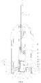
FIG. 1 is a front view of an electronic cigarette according to the first embodiment of the present disclosure; -
FIG. 2 is a left side view of the electronic cigarette shown inFIG. 1 ; -
FIG. 3 is a cross-sectional view along A-A of the electronic cigarette shown inFIG. 1 ; -
FIG. 4 is an enlarged view of the cartridge in the electronic cigarette shown inFIG. 3 . - The part names and their reference signs in the drawings are as follows:
cartridge 10liquid storage cavity 110cartridge housing 11vent tube 11engaging protrusion 113sealing member 12first blind hole 121second blind hole 122through hole 123 first electrode 13second electrode 14atomizing head 15atomizing tube 151 heating structure 152 atomizing cavity 150pin 1523liquid guiding member 1521 heating member 1522 liquid inlet 1511fixing sleeve 153 communication hole 1531base seat 16 first mounting groove 161second mounting groove 162sensing through hole 163sleeve pipe 17connecting portion 171lifting rod 18power supply device 20battery housing 21partition plate 211 battery mounting groove 212cartridge mounting groove 213engaging groove 2131gap 2111first pole 2112second pole 2113 mounting column 2114sensing passage 2115battery 22sensor 23 - The present application will now be described in detail with reference to the drawings. This figure is a simplified schematic diagram, which only illustrates the basic structure of the present application in a schematic manner, so it only shows the structure related to the present application.
- Referring to
FIG. 1 andFIG. 2 , the first embodiment of the present disclosure provides an electronic cigarette. The electronic cigarette includes acartridge 10 and apower supply device 20 electrically connected to thecartridge 10. During working, thepower supply device 20 supplies power to thecartridge 10, so that the e-liquid stored in thecartridge 10 is atomized to generate smoke, and the smoke can be inhaled by the user. - Please refer to
FIGs. 3 and4 , thecartridge 10 includes acartridge housing 11 having aliquid storage cavity 110 therein, a sealingmember 12 used for sealing theliquid storage cavity 110, and afirst electrode 13 and asecond electrode 14 installed on the sealingmember 12. A firstblind hole 121 for installing thefirst electrode 13 and a secondblind hole 122 for installing thesecond electrode 14 are provided on an end surface of the sealingmember 12 away from theliquid storage cavity 110. The sealingmember 12 is made of an elastic material, and a liquid injection needle pierces the sealingmember 12 through the wall of at least one of the firstblind hole 121 and the secondblind hole 122 and then communicates with theliquid storage cavity 110 to inject e-liquid into theliquid storage cavity 110. After the liquid injection is finished, the liquid injection needle is pulled out and the sealingmember 12 forms a self-sealing at the pierced position, then the firstblind hole 121 is sealed by thefirst electrode 13, and the secondblind hole 122 is sealed by thesecond electrode 14. - According to the
cartridge 10 of the present disclosure, the sealingmember 12 can be pierced by the liquid injection needle, so as to facilitate the injection of e-liquid into theliquid storage cavity 110 through the liquid injection needle, and after the liquid injection needle is pulled out, the pierced position on the sealingmember 12 can automatically restore to seal theliquid storage cavity 110 again, to prevent the e-liquid in theliquid storage cavity 110 from leaking after the liquid injection is finished. In addition, after the liquid injection is finished, the firstblind hole 121 and the secondblind hole 122 are respectively sealed by thefirst electrode 13 and thesecond electrode 14. Thus, even if the e-liquid in theliquid storage cavity 110 leaks through the pierced position, the leaked e-liquid can also be sealed by thefirst electrode 13 and/or thesecond electrode 14, to further prevent the leakage of the e-liquid from leaking and avoid causing corrosion to thepower supply device 20 due to the leakage of the e-liquid. - In a specific embodiment, the sealing
member 12 can be made of a soft material with elastic deformation ability, which may be a highly elastic polymer such as rubber or silicone. It is understood that, in other embodiments, the sealingmember 12 can also be made of a self-healing material. Thus, the sealingmember 12 can be pierced by a sharp object (for example, a liquid injection needle), and after the sharp object is pulled out, the sealingmember 12 can automatically restore to seal again. The sealingmember 12 is used to seal theliquid storage cavity 110, so as to prevent the e-liquid in theliquid storage cavity 110 from leaking during transportation, storage or use. Further, after thecartridge 10 is assembled, the liquid injection needle pierces the sealingmember 12 and injects e-liquid into theliquid storage cavity 110, and after the liquid injection needle is pulled out, the sealingmember 12 automatically restores to seal theliquid storage cavity 110 again. - In addition, the arrangement of the first
blind hole 121 and the secondblind hole 122, on the one hand, can be respectively used for the installation of thefirst electrode 13 and thesecond electrode 14, and on the other hand, the blind hole reduces the thickness of the sealingmember 12 at the pierced position, so that the liquid injection needle can pierce the sealingmember 12 more easily. However, the remaining part of the sealingmember 12 still maintains a relatively large thickness, so as to make the sealing connection between the sealingmember 12 and thecartridge housing 11 more stable and prevent the e-liquid in theliquid storage cavity 110 from leaking through the connection position between the sealingmember 12 and thecartridge housing 11. - In a specific embodiment, during the liquid injection, the liquid injection needle pierces the sealing
member 12 through the bottom wall of the firstblind hole 121 and then communicates with theliquid storage cavity 110 for liquid injection operation. In order to ensure the balance of the air pressure in theliquid storage cavity 110, that is, to ensure that the air in theliquid storage cavity 110 is automatically discharged during the liquid injection operation, a cut is provided on the wall of the secondblind hole 122, the cut can be self-sealed when not filling the e-liquid. However, when filling the e-liquid, the pressure in theliquid storage cavity 110 increases, and the cut can be pushed open under the pressure, so that the air in theliquid storage cavity 110 can be discharged through the opened cut. It is understood that, in other embodiments, the liquid injection needle pierces the sealingmember 12 through the wall of the secondblind hole 122 to perform liquid injection. Optionally, there are two liquid injection needles, and the two liquid injection needles pierce the sealingmember 12 through the wall of the firstblind hole 121 and the wall of the secondblind hole 122 respectively, so as to simultaneously perform liquid injection; at this time, in order to discharge the air in theliquid storage cavity 110, a through hole communicating with theliquid storage cavity 110 is provided at one end of thecartridge housing 11 opposite to the sealingmember 12, and the air in theliquid storage cavity 110 is discharged from the through hole during liquid injection. In addition, the liquid injection needle can also pierce the sealingmember 12 through the side wall of the firstblind hole 121 and/or the secondblind hole 122 to perform liquid injection, and the pierced position of the liquid injection needle in the blind hole is not limited. It should be noted that, in order to prevent the e-liquid in theliquid storage cavity 110 from leaking from the air discharging end of thecartridge 10, it is only necessary to adjust the air discharging end of thecartridge 10 to be located on the top of thecartridge 10 during the liquid injection process. - Please refer to
FIGs. 3 and4 again, thecartridge 10 further includes anatomizing head 15 received in theliquid storage cavity 110. The atomizinghead 15 includes an atomizing tube 151 having anatomizing cavity 150 and a heating structure 152 received in theatomizing cavity 150. The atomizing tube 151 is connected to the sealingmember 12. The heating structure 152 has the ability to absorb the e-liquid, and can generate heat after being energized. The heating structure 152 has twopins 1523 extending to the outside of theliquid storage cavity 110, and the ends of the twopins 1523 extending to the outside of theliquid storage cavity 110 are each bent. The bent end of one of thepins 1523 extends into the firstblind hole 121 and is squeezed and fixed on the side wall of the firstblind hole 121 by thefirst electrode 13, and the bent end of theother pin 1523 extends into the secondblind hole 122 and is squeezed and fixed on the side wall of the secondblind hole 122 by thesecond electrode 14. Therefore, while the function of electrically connecting the twopins 1523 of the heating structure 152 with thefirst electrode 13 and thesecond electrode 14 is realized, the fixing function of the heating structure 152 is also realized. In addition, when the user needs to disassemble or replace the heating structure 152, the user only needs to remove thefirst electrode 13 and thesecond electrode 14, so as to release thepins 1523 from squeezing; then the heating structure 152 can be easily removed, the operation is simple and convenient, and the user experience is improved. In addition, the twopins 1523 of the heating structure 152 are not immersed in theliquid storage cavity 110, so as to prevent thepins 1523 from being corroded by the e-liquid. - In this embodiment, the heating structure 152 is a ceramic heating body, that is, while the ceramic heating body has the ability to absorb the e-liquid, it also has the ability to heat the e-liquid. It is understood that, in other embodiments, the heating structure 152 includes a liquid guiding member 1521 and a heating member 1522 that are in contact with each other. The liquid guiding member 1521 is a member capable of absorbing the e-liquid, such as cotton, sponge, fiber rope, porous ceramic or porous graphite, etc. The heating member 133 is a member that has the ability to heat the e-liquid after being energized, such as a heating plate, a heating net, or a heating rod. It is understood that, the heating structure 152 may also be an ultrasonic heating device or a heating tube, etc., which is not limited here.
- In a specific embodiment, the
cartridge housing 11 is generally a hollow cylindrical structure with an opening at the lower end. Thecartridge housing 11 has a flat structure, which serves as the contour of thecartridge 10 and can effectively prevent thecartridge 10 from rolling off and avoid thecartridge 10 from falling off. Theliquid storage cavity 110 is formed by the inner cavity of thecartridge housing 11, and the e-liquid is stored in theliquid storage cavity 110. The sealingmember 12 seals the opening at the lower end of thecartridge housing 11. Thecartridge housing 11 is made of a transparent or translucent material, so that the user can observe the amount of the e-liquid in theliquid storage cavity 110 through thecartridge housing 11, which is convenient for the user to inject the liquid in time. In this embodiment, thecartridge housing 11 is made of translucent plastic. - In addition, the center of the upper end surface of the
cartridge housing 11 extends downward along the axial direction of thecartridge housing 11 to form avent tube 111. The upper and lower ends of thevent tube 111 are opened, and the upper end of thevent tube 111 passes through the upper end surface of thecartridge housing 11 to form a smoke outlet. The sealingmember 12 is located at the opposite end of thecartridge housing 11 relative to the smoke outlet. In addition, the lower end of thevent tube 111 is in communication with theatomizing cavity 150, so that the smoke in theatomizing cavity 150 enters the user's mouth through thevent tube 111. - The sealing
member 12 is generally a block structure. The sealingmember 12 is received in the lower end of thecartridge housing 11 to seal theliquid storage cavity 110. Specifically, theliquid storage cavity 110 is formed by a space enclosed between the inner wall of thecartridge housing 11, the outer wall of thevent tube 111 and the upper end surface of the sealingmember 12. A through hole 123 is provided in the center of the sealingmember 12 along the axial direction of the sealingmember 12, and the through hole 123 passes through the upper and lower end surfaces of the sealingmember 12. The atomizing tube 151 is connected to the through hole 123. The twopins 1523 of the heating structure 152 pass through the through hole 123 and then extend to the outside of theliquid storage cavity 110. In addition, the firstblind hole 121 and the secondblind hole 122 are provided on the lower end surface of the sealingmember 12 and symmetrically arranged on both sides of the through hole 123. That is, the firstblind hole 121 and the secondblind hole 122 are symmetrically arranged with respect to the central axis of thecartridge housing 11. - The atomizing tube 151 is generally a hollow cylindrical structure with both ends opened. The
atomizing cavity 150 is formed by the inner cavity of the atomizing tube 151. The lower end of the atomizing tube 151 is hermetically inserted into the through hole 123, and the upper end of the atomizing tube 151 is received in theliquid storage cavity 110. The side wall of the atomizing tube 151 is provided with aliquid inlet 1511, and theliquid inlet 1511 is in communication with theliquid storage cavity 110 and theatomizing cavity 150. In use, the e-liquid in theliquid storage cavity 110 enters theatomizing cavity 150 through theliquid inlet 1511 to contact the heating structure 152, and then generates smoke under the heating action of the heating structure 152. - In addition, the atomizing
head 15 further includes a fixing sleeve 153. The fixing sleeve 153 is sandwiched between the inner circumferential surface of the atomizing tube 151 and the outer circumferential surface of the heating structure 152. The fixing sleeve 153 is made of a high temperature resistant material such as silicone or rubber. By providing the fixing sleeve 153, the connection stability between the heating structure 152 and the atomizing tube 151 is increased, and the heating structure 152 and the atomizing tube 151 are prevented from being separated. Meanwhile, the side wall of the fixing sleeve 153 is provided with acommunication hole 1531, thecommunication hole 1531 is in communication with theliquid inlet 1511 and the heating structure 152, so that the e-liquid in theliquid storage cavity 110 sequentially passes through theliquid inlet 1511 and thecommunication hole 1531 and then comes into contact with the heating structure 152. - In a specific embodiment, the
cartridge 10 further includes a base seat 16. The base seat 16 covers on the lower end of thecartridge housing 11 and is located outside theliquid storage cavity 110. The upper end surface of the base seat 16 resists the lower end surface of the sealingmember 12, thereby supporting the sealingmember 12 made of an elastic material and preventing the sealingmember 12 from easily deforming and thus affecting the sealing effect of the e-liquid. In addition, the base seat 16 and thecartridge housing 11 can be connected by screw connection, snapping connection, plugging connection, or magnetic connection, which is not limited here. - Referring to
FIG. 4 , in a specific embodiment, the lower end surface of the base seat 16 is recessed to form a first mountinggroove 161 and asecond mounting groove 162. Thefirst mounting groove 161 corresponds to the firstblind hole 121, and the size of the first mountinggroove 161 is larger than the size of the firstblind hole 121. Thesecond mounting groove 162 corresponds to the secondblind hole 122, and the size of the second mountinggroove 162 is larger than the size of the secondblind hole 122. Both thefirst electrode 13 and thesecond electrode 14 have a trapezoidal structure, the upper end of thefirst electrode 13 passes through the bottom wall of the first mountinggroove 161 and then is tightly inserted into the firstblind hole 121, and the lower end of thefirst electrode 13 is received in the first mountinggroove 161 and resists the bottom wall of the first mountinggroove 161. The upper end of thesecond electrode 14 passes through the bottom wall of the second mountinggroove 162 and then is tightly inserted into the secondblind hole 122, and the lower end of thesecond electrode 14 is received in the second mountinggroove 161 and resists the bottom wall of the second mountinggroove 162. Therefore, the insertion depth of thefirst electrode 13 in the firstblind hole 121 and the insertion depth of thesecond electrode 14 in the secondblind hole 122 are limited, thereby preventing thefirst electrode 13 and thesecond electrode 14 from being inserted excessively to push open the pierced position, which may lead to the leakage of the e-liquid. It should be noted that after thefirst electrode 13 and thesecond electrode 14 are installed in place, the lower end surface of thefirst electrode 13 and the lower end surface of thesecond electrode 14 are flush with the lower end surface of the base seat 16, so as to make thecartridge 10 more beautiful. It is understood that, in other embodiments, both the first mountinggroove 162 and the second mountinggroove 162 may also be omitted, the upper end of thefirst electrode 13 passes through the base seat 16 and is tightly inserted into the firstblind hole 121 to seal the firstblind hole 121, the lower end of thefirst electrode 13 is located outside the base seat 16 and resists the lower end surface of the base seat 16, the upper end of thesecond electrode 14 passes through the base seat 16 and is tightly inserted into the secondblind hole 122 to seal the secondblind hole 122, and the lower end of thesecond electrode 14 is located outside the base seat 16 and resists the lower end surface of the base seat 16. In addition, in order to achieve electrical insulation and avoid short circuit, the base seat 16 is made of an insulating hard material. In this embodiment, the base seat 16 is made of plastic. - In addition, the lower end surface of the base seat 16 is provided with a sensing through
hole 163 communicating with theatomizing cavity 150 along the axial direction of the base seat 16. The sensing throughhole 163 is located at the center of the base seat 16, and the first mountinggroove 161 and the second mountinggroove 162 are symmetrically arranged on both sides of the sensing throughhole 163. In a specific embodiment, the lower end surface of the base seat 16 is also provided with an air inlet hole communicating with theatomizing cavity 150, and the air inlet hole is located at one side of the sensing throughhole 163. - It is understood that, in other embodiments not shown, the base seat 16 may also be omitted, the
first electrode 14 is completely inserted into the firstblind hole 121, and thesecond electrode 15 is completely inserted into the secondblind hole 122. Thus, it is only necessary that thefirst electrode 14 is at least partially inserted into the firstblind hole 121 tightly and the inserted portion of thefirst electrode 13 seals the firstblind hole 121, and thesecond electrode 15 is at least partially inserted into the secondblind hole 122 tightly and the inserted portion of thesecond electrode 14 seals the secondblind hole 122. - In a specific embodiment, the
cartridge 10 further includes an isolating assembly, and the isolating assembly includes asleeve pipe 17 and a liftingrod 18. Thesleeve pipe 17 has a hollow cylindrical structure with an opening at the lower end. Thesleeve pipe 17 is slidably sleeved on the outside of the atomizing tube 151 along the axial direction of the atomizinghead 15. The liftingrod 18 has a rod-shaped structure and is slidably received in thevent tube 111, the lower end of the liftingrod 18 is connected with the upper end of thesleeve pipe 17, and the upper end of the liftingrod 18 passes through the opening at the upper end of thevent tube 111 and then extends to the outside of thecartridge housing 11. When thecartridge 10 leaves the factory, thesleeve pipe 17 is sleeved on the outside of the atomizing tube 151 corresponding to theliquid inlet 1511 in order to seal theliquid inlet 1511, so as to prevent the e-liquid in theliquid storage cavity 110 from entering the atomizinghead 15 through theliquid inlet 1511, thereby isolating the e-liquid from the external air, which can prevent the e-liquid from entering the atomizinghead 15 and contacting the air due to the change in temperature and air pressure during the transportation process, and also prevent the e-liquid from leaking due to too much e-liquid entering the atomizinghead 15. In use, the liftingrod 18 is pulled upwards by the user, thesleeve pipe 17 is driven by the liftingrod 18 to move upward together to open theliquid inlet 1511, so that the e-liquid communicates with theatomizing cavity 150 through theliquid inlet 1511. When the liftingrod 18 continues to be pulled upward until the upper end surface of thesleeve pipe 17 resists the lower end surface of thevent tube 111, the liftingrod 18 can be separated from thesleeve pipe 17, and then the liftingrod 18 can be drawn out from thevent tube 111, thevent tube 111 is opened, and at this time, theatomizing cavity 150 is in communication with the inner cavity of thevent tube 111 through thesleeve pipe 17. - It is understood that, the
sleeve pipe 17 is made of silicone or rubber material to facilitate the sealing effect on theliquid inlet 1511 when thecartridge 10 leaves the factory, and to facilitate the deformation of thesleeve pipe 17 to separate it from the liftingrod 18. In this embodiment, thesleeve pipe 17 and the liftingrod 18 are integrally formed, and the connection point between thesleeve pipe 17 and the liftingrod 18 is pulled apart so that thesleeve pipe 17 is separated from the liftingrod 18. - In addition, the upper end surface of the
sleeve pipe 17 extends upward along the axial direction of thesleeve pipe 17 to form a connectingportion 171, the connectingportion 171 is sleeved on thevent tube 111 so that thesleeve pipe 17 is connected to thevent tube 111, which can prevent the e-liquid from leaking through the gap between thesleeve pipe 17 and thevent tube 111, and play a guiding function during the movement of thesleeve pipe 17. - Please refer to
FIG. 3 , thepower supply device 20 includes abattery housing 21 and abattery 22 and asensor 23 mounted in thebattery housing 21. - In a specific embodiment, the
battery housing 21 is generally a hollow cylindrical structure with an opening at the upper end. A partition plate 211 is provided inside thebattery housing 21 along the radial direction of thebattery housing 21, the partition plate 211 divides the inner cavity of thebattery housing 21 into abattery mounting groove 212 for installing thebattery 22 and acartridge mounting groove 213 for installing thecartridge 10, and thebattery mounting groove 212 is located at one end of thebattery housing 21 away from the opening of thebattery housing 21. Thecartridge 10 is connected to thebattery housing 21 through the opening of thebattery housing 21. Specifically, two opposite sides of thecartridge housing 11 are provided with engagingprotrusions 113, the inner wall of thecartridge mounting groove 213 is provided with engaginggrooves 2131 corresponding to the engagingprotrusions 113. When thecartridge 10 is inserted into thebattery housing 21, the engagingprotrusions 113 are respectively engaged with the engaginggrooves 2131 to stabilize the connection between thecartridge 10 and thepower supply device 20. - In addition, when the
cartridge 10 and thepower supply device 20 are installed in place, agap 2111 is formed between the lower end surface of the base seat 16 and the upper end surface of the partition plate 211. Thegap 2111 is in communication with the air inlet hole and the outside environment, so that the external air can easily enter the inside of thecartridge 10. - A
first pole 2112 and a second pole 2113 are respectively installed on the partition plate 211, thefirst pole 2112 is electrically connected to one of the positive and negative electrodes of thebattery 22, and the second pole 2113 is electrically connected to the other of the positive and negative electrodes of thebattery 22. When thecartridge 10 and thepower supply device 20 are installed in place, thefirst pole 2112 is in contact with and electrically connected to thefirst electrode 13, the second pole 2113 is in contact with and electrically connected to thesecond electrode 14, thereby realizing the function of thebattery 22 to supply power to the heating structure 152. - In addition, a mounting
column 2114 protrudes from the upper end surface of the partition plate 211 corresponding to the sensing throughhole 163, asensing passage 2115 is provided in the mountingcolumn 2114, the upper end of thesensing passage 2115 penetrates the upper end surface of the mountingcolumn 2114, and the lower end of thesensing passage 2115 penetrates the lower end surface of the partition plate 211. Thefirst pole 2112 and the second pole 2113 are symmetrically arranged on both sides of the mountingcolumn 2114, that is, thefirst pole 2112 and the second pole 2113 are symmetrically arranged with respect to the central axis of thecartridge housing 11. In this way, when thecartridge 10 is installed on thepower supply device 20, there is no need to consider the positive and negative polarities, and the effect that front side installation and back side installation can both be used is achieved. Specifically, when thecartridge 10 and thepower supply device 20 are installed in a first connection state, thefirst pole 2112 is in contact with and electrically connected to thefirst electrode 13; when thecartridge 10 and thepower supply device 20 are installed in a second connection state, the first pole 2113 is in contact with and electrically connected to thesecond electrode 14. In this embodiment, the transition from the first connection state to the second connection state can be obtained by rotating thepower supply device 20 relative to thecartridge 10 by 180° , so as to achieve the purpose of electrical conduction for both front side installation and back side installation. Thesensor 23 is installed at the lower end of the partition plate 211 to close thesensing passage 2115, and the sensing end of thesensor 23 is in communication with thesensing passage 2115. When thecartridge 10 and thepower supply device 20 are installed in place, the mountingcolumn 2114 is partially inserted into the base seat 16, and thesensing passage 2115 is in communication with the sensing throughhole 163. - In a specific embodiment, the
power supply device 20 further includes a circuit board, and both thebattery 22 and thesensor 23 are electrically connected to the circuit board. Thesensor 23 is a pressure sensor. When the user sucks, a negative pressure is generated in thesensing passage 2115 due to the suction effect, thesensor 23 senses the air pressure change in thesensing passage 2115 and transmits the signal corresponding to the air pressure change to the circuit board; after receiving the signal, the circuit board controls thebattery 22 to supply power to the heating structure 152 for heating the e-liquid, so that the e-liquid generates smoke under the heating action, thereby realizing automatic control. It is understood that thesensor 23 may also be an airflow sensor. - In the
cartridge 10 provided by the present disclosure, the sealingmember 12 can be pierced by the liquid injection needle, so as to facilitate the injection of e-liquid into theliquid storage cavity 110 through the liquid injection needle, and after the liquid injection needle is pulled out, the pierced position on the sealingmember 12 can automatically restore to seal theliquid storage cavity 110 again, thereby preventing the e-liquid in theliquid storage cavity 110 from leaking after the liquid injection is finished. In addition, after the liquid injection is finished, the firstblind hole 121 and the secondblind hole 122 are respectively sealed by thefirst electrode 13 and thesecond electrode 14. In this way, even if the e-liquid in theliquid storage cavity 110 leaks through the pierced position, the leaked e-liquid can also be sealed by thefirst electrode 13 and/or thesecond electrode 14, to further prevent the e-liquid from leaking. - The present disclosure provides the electronic cigarette of the first embodiment. Because it has all the technical features of the above-mentioned
cartridge 10, it has the same technical effects as the above-mentionedcartridge 10. - In the second embodiment of the present disclosure, a liquid injection method for a cartridge is also disclosed, which is used to inject liquid into the cartridge of an electronic cigarette. In a specific embodiment, the cartridge is the
cartridge 10 as described in the first embodiment. Thecartridge 10 includes acartridge housing 11 with aliquid storage cavity 110, a sealingmember 12 for sealing theliquid storage cavity 110, and afirst electrode 13 and asecond electrode 14. A firstblind hole 121 for installing thefirst electrode 13 and a secondblind hole 122 for installing thesecond electrode 14 are provided on an end surface of the sealingmember 12 away from theliquid storage cavity 110. The sealingmember 12 is made of an elastic material. The liquid injection method includes: - step 1: the liquid injection needle pierces the sealing
member 12 through the wall of at least one of the firstblind hole 121 and the secondblind hole 122 and then communicates with theliquid storage cavity 110 to inject e-liquid into theliquid storage cavity 110; - step 2: after the liquid injection is finished, the liquid injection needle is pulled out and the sealing
member 12 forming a self-sealing at the pierced position; and - step 3: the first
blind hole 121 is sealed by thefirst electrode 13, and the secondblind hole 122 is sealed by thesecond electrode 14. - In addition, a cut is provided on the wall of the second
blind hole 122, during the liquid injection process, the pressure in theliquid storage cavity 110 increases so that the cut is pushed open, and the air in theliquid storage cavity 110 is discharged through the cut. - In the liquid injection method for the cartridge according to the second embodiment of the present disclosure, after the liquid injection needle is pulled out, the pierced position on the sealing
member 12 can automatically restore to seal theliquid storage cavity 110 again, so as to prevent the e-liquid in theliquid storage cavity 110 from leaking after the liquid injection is finished. In addition, after the liquid injection is finished, the firstblind hole 121 and the secondblind hole 122 are sealed by thefirst electrode 13 and thesecond electrode 14, respectively. In this way, even if the e-liquid in theliquid storage cavity 110 leaks through the pierced position, the leaked e-liquid can also be sealed by thefirst electrode 13 and/or thesecond electrode 14 to further prevent the e-liquid from leaking. - Taking the above-mentioned ideal embodiments according to the present application as enlightenment, through the above description, the relevant staff can make various changes and modifications without departing from the concept of the present application. The technical scope of the present application is not limited to the content of the specification, and its technical scope must be determined according to the scope of the claims.
Claims (12)
- A cartridge comprising a cartridge housing having a liquid storage cavity therein, a sealing member used for sealing the liquid storage cavity, and a first electrode and a second electrode installed on the sealing member, wherein a first blind hole and a second blind hole are provided on an end surface of the sealing member away from the liquid storage cavity, the sealing member is made of an elastic material such that a liquid injection needle is adapted to pierce the sealing member through the wall of at least one of the first blind hole and the second blind hole and then communicate with the liquid storage cavity to inject e-liquid into the liquid storage cavity, and after the liquid injection is finished and the liquid injection needle is pulled out, the sealing member forms a self-sealing at the pierced position, the first blind hole is then sealed by the first electrode, and the second blind hole is then sealed by the second electrode.
- The cartridge according to claim 1, wherein the first electrode is at least partially inserted into the first blind hole tightly and the inserted portion of the first electrode seals the first blind hole, the second electrode is at least partially inserted into the second blind hole tightly and the inserted portion of the second electrode seals the second blind hole.
- The cartridge according to claim 2, wherein the cartridge further comprises an atomizing head, the atomizing head is received in the liquid storage cavity, the atomizing head comprises a heating structure, the heating structure has two pins extending to the outside of the liquid storage cavity; the first electrode squeezes and fixes a part of one of the pins that extends to the outside of the liquid storage cavity on a side wall of the first blind hole and is electrically connected to the pin; the second electrode squeezes and fixes a part of the other pin that extends to the outside of the liquid storage cavity on a side wall of the second blind hole and is electrically connected to the other pin.
- The cartridge according to claim 3, wherein the atomizing head further comprises an atomizing tube, an atomizing cavity communicating with the liquid storage cavity is provided in the atomizing tube, the heating structure is received in the atomizing cavity, the sealing member is provided with a through hole, one end of the atomizing tube is hermetically inserted into the through hole, the two pins of the heating structure pass through the through hole and then extend to the outside of the liquid storage cavity.
- The cartridge according to claim 2, wherein the cartridge further comprises a base seat, the base seat is located outside the liquid storage cavity and resists the end surface of the sealing member away from the liquid storage cavity, one end of the first electrode passes through the base seat and is tightly inserted into the first blind hole, one end of the second electrode passes through the base seat and is tightly inserted into the second blind hole.
- The cartridge according to claim 5, wherein the base seat is provided with a first mounting groove corresponding to the first blind hole and a second mounting groove corresponding to the second blind hole, one end of the first electrode passes through a bottom wall of the first mounting groove and then is inserted into the first blind hole, the other end of the first electrode resists the bottom wall of the first mounting groove; one end of the second electrode passes through a bottom wall of the second mounting groove and then is inserted into the second blind hole, the other end of the second electrode resists the bottom wall of the second mounting groove.
- The cartridge according to claim 1, wherein the cartridge is provided with a smoke outlet located at one end of the cartridge housing, the sealing member is located at an opposite end of the cartridge housing relative to the smoke outlet, the first electrode and the second electrode are symmetrically arranged with respect to a central axis of the cartridge housing.
- An electronic cigarette comprising the cartridge according to any one of claims 1 to 7.
- The electronic cigarette according to claim 8, wherein the cartridge further comprises a power supply device, the power supply device comprises a battery housing and a battery, the battery housing has an opening, a partition plate is provided in the battery housing, the partition plate divides an inner cavity of the battery housing into a battery mounting groove for installing the battery and a cartridge mounting groove for installing the cartridge; the battery mounting groove is located at one end of the battery housing away from the opening.
- The electronic cigarette according to claim 9, wherein a first pole and a second pole are respectively installed on the partition plate, the first pole is electrically connected to one of the positive and negative electrodes of the battery, the second pole is electrically connected to the other of the positive and negative electrodes of the battery; when the cartridge and the power supply device are installed in a first connection state, the first pole is in contact with and electrically connected to the first electrode; when the cartridge and the power supply device are installed in a second connection state, the first pole is in contact with and electrically connected to the second electrode.
- A liquid injection method for the cartridge according to any one of claims 1 to 7 and the electronic cigarette according to any one of claims 8 to 10, the liquid injection method comprising the following steps:step 1: the liquid injection needle pierces the sealing member through the wall of at least one of the first blind hole and the second blind hole and then communicates with the liquid storage cavity to inject e-liquid into the liquid storage cavity;step 2: after the liquid injection is finished, the liquid injection needle is pulled out and the sealing member forms a self-sealing at the pierced position; andstep 3: the first blind hole is sealed by the first electrode, and the second blind hole is sealed by the second electrode.
- The liquid injection method according to claim 11, wherein a cut is provided on the wall of the second blind hole, during the liquid injection process, the pressure in the liquid storage cavity increases so that the cut is pushed open, and the air in the liquid storage cavity is discharged through the cut.
Applications Claiming Priority (2)
| Application Number | Priority Date | Filing Date | Title |
|---|---|---|---|
| CN201910477168.4A CN112021680B (en) | 2019-06-03 | 2019-06-03 | Liquid injection method of cartridge, cartridge and electronic cigarette |
| PCT/CN2020/094066 WO2020244532A1 (en) | 2019-06-03 | 2020-06-03 | E-liquid injection method for cartridge, cartridge and electronic cigarette |
Publications (2)
| Publication Number | Publication Date |
|---|---|
| EP3977878A1 true EP3977878A1 (en) | 2022-04-06 |
| EP3977878A4 EP3977878A4 (en) | 2023-08-30 |
Family
ID=73575956
Family Applications (1)
| Application Number | Title | Priority Date | Filing Date |
|---|---|---|---|
| EP20819143.7A Pending EP3977878A4 (en) | 2019-06-03 | 2020-06-03 | E-liquid injection method for cartridge, cartridge and electronic cigarette |
Country Status (4)
| Country | Link |
|---|---|
| US (1) | US12329198B2 (en) |
| EP (1) | EP3977878A4 (en) |
| CN (1) | CN112021680B (en) |
| WO (1) | WO2020244532A1 (en) |
Families Citing this family (8)
| Publication number | Priority date | Publication date | Assignee | Title |
|---|---|---|---|---|
| EP4152982B1 (en) * | 2020-05-21 | 2025-07-30 | Juul Labs, Inc. | One-piece shell for vaporizer device |
| CN216853793U (en) * | 2021-05-16 | 2022-07-01 | 深圳易佳特科技有限公司 | A separator and atomizer for atomizer |
| EP4091481A1 (en) * | 2021-05-16 | 2022-11-23 | Shenzhen Eigate Technology Co., Ltd. | Atomizer and electronic cigarette comprising the same |
| US20220378097A1 (en) * | 2021-05-28 | 2022-12-01 | Shenzhen Eigate Technology Co., Ltd. | Atomizer and electronic cigarette comprising the same |
| US20240049799A1 (en) * | 2021-10-20 | 2024-02-15 | Shenzhen Zun Yi Pin Technology Co., Ltd. | Liquid injection device and method |
| CN115191654A (en) * | 2022-07-05 | 2022-10-18 | 深圳市吉迩科技有限公司 | Diaphragm formula atomizer and have electron cigarette of this atomizer |
| WO2024066276A1 (en) * | 2022-09-28 | 2024-04-04 | 爱奇迹(香港)有限公司 | Electrical connecting member, connecting assembly, and device |
| CN120957629A (en) * | 2023-08-01 | 2025-11-14 | 韩国烟草人参公社 | Aerosol generating device |
Family Cites Families (10)
| Publication number | Priority date | Publication date | Assignee | Title |
|---|---|---|---|---|
| MX377347B (en) * | 2016-02-11 | 2025-03-07 | Juul Labs Inc | Fillable vaporizer cartridge and method of filling |
| CN108887746A (en) * | 2016-02-27 | 2018-11-27 | 卓尔悦欧洲控股有限公司 | Electronic cigarette |
| CN206433758U (en) * | 2016-11-22 | 2017-08-25 | 卓尔悦欧洲控股有限公司 | Liquid storage component, atomizer and its electronic cigarette |
| CN207678853U (en) * | 2017-12-18 | 2018-08-03 | 常州市派腾电子技术服务有限公司 | Fluid injection sealing structure, smoke grenade and its electronic cigarette |
| CN208354608U (en) * | 2018-06-22 | 2019-01-11 | 湖南中烟工业有限责任公司 | A kind of electronic smoke atomizer and the electronic cigarette |
| CN208849515U (en) * | 2018-10-26 | 2019-05-10 | 常州市派腾电子技术服务有限公司 | Charge Status Indicating Circuits and Electronics |
| CN109619691B (en) * | 2019-01-19 | 2021-10-08 | 常州市派腾电子技术服务有限公司 | Liquid injection method of cartridge, cartridge and electronic cigarette |
| CN109700075B (en) * | 2019-01-21 | 2021-08-27 | 常州市派腾电子技术服务有限公司 | Liquid injection method and liquid injection mechanism for cigarette cartridge |
| CN109717519B (en) * | 2019-03-13 | 2021-07-27 | 常州市派腾电子技术服务有限公司 | e-cigarette |
| CN210137810U (en) * | 2019-06-03 | 2020-03-13 | 常州市派腾电子技术服务有限公司 | Cartridges and Electronic Cigarettes |
-
2019
- 2019-06-03 CN CN201910477168.4A patent/CN112021680B/en active Active
-
2020
- 2020-06-03 EP EP20819143.7A patent/EP3977878A4/en active Pending
- 2020-06-03 WO PCT/CN2020/094066 patent/WO2020244532A1/en not_active Ceased
-
2021
- 2021-10-07 US US17/450,211 patent/US12329198B2/en active Active
Also Published As
| Publication number | Publication date |
|---|---|
| US20220022538A1 (en) | 2022-01-27 |
| EP3977878A4 (en) | 2023-08-30 |
| WO2020244532A1 (en) | 2020-12-10 |
| CN112021680B (en) | 2025-07-18 |
| US12329198B2 (en) | 2025-06-17 |
| CN112021680A (en) | 2020-12-04 |
Similar Documents
| Publication | Publication Date | Title |
|---|---|---|
| US12329198B2 (en) | Liquid injection method of cartridge, cartridge and electronic cigarette | |
| EP3903610A1 (en) | Cartridge and electronic cigarette | |
| CN211746945U (en) | Nebulizer and aerosol generating device | |
| CN204994614U (en) | Atomizer of liquid can be annotated and electron cigarette of this atomizer is used | |
| CN104738816B (en) | Atomizer, electronic cigarette and liquid storage device suitable for replacement | |
| US12082610B2 (en) | Cartridge and electronic cigarette | |
| CN109619700A (en) | Smoke grenade, electrolyte filling method, control method and the electronic cigarette of electronic cigarette | |
| EP3903608A1 (en) | Battery housing and electronic cigarette, and assembly method | |
| CN203851815U (en) | Electronic atomization device and electronic cigarette | |
| CN210137810U (en) | Cartridges and Electronic Cigarettes | |
| CN209436272U (en) | Pods and Electronic Cigarettes | |
| CN210158009U (en) | Atomizers and Electronic Cigarettes | |
| US20210315281A1 (en) | Power supply device, electronic cigarette, and assembly method | |
| CN220109122U (en) | Atomizer and electronic atomization device | |
| CN209376682U (en) | Smoke grenade and electronic cigarette | |
| CN114246377B (en) | Electronic atomization device and its host and atomizer | |
| CN210158011U (en) | Atomizer and electronic cigarette | |
| CN210538910U (en) | Electronic cigarette atomizer | |
| CN222486175U (en) | Sealed oil storage assembly and electronic atomization device | |
| CN210929616U (en) | High leakproofness push type oiling electron cigarette | |
| EP4430970A1 (en) | Atomization device, liquid storage device, and atomization assembly | |
| CN216796485U (en) | Atomizer and aerosol generating device | |
| CN216315585U (en) | Atomizer and atomization device | |
| CN213307425U (en) | Aerosol generating device | |
| CN210184530U (en) | But electron smog spinning disk atomiser and electron cigarette of oiling |
Legal Events
| Date | Code | Title | Description |
|---|---|---|---|
| STAA | Information on the status of an ep patent application or granted ep patent |
Free format text: STATUS: THE INTERNATIONAL PUBLICATION HAS BEEN MADE |
|
| PUAI | Public reference made under article 153(3) epc to a published international application that has entered the european phase |
Free format text: ORIGINAL CODE: 0009012 |
|
| STAA | Information on the status of an ep patent application or granted ep patent |
Free format text: STATUS: REQUEST FOR EXAMINATION WAS MADE |
|
| 17P | Request for examination filed |
Effective date: 20211229 |
|
| AK | Designated contracting states |
Kind code of ref document: A1 Designated state(s): AL AT BE BG CH CY CZ DE DK EE ES FI FR GB GR HR HU IE IS IT LI LT LU LV MC MK MT NL NO PL PT RO RS SE SI SK SM TR |
|
| DAV | Request for validation of the european patent (deleted) | ||
| DAX | Request for extension of the european patent (deleted) | ||
| REG | Reference to a national code |
Ref country code: DE Ref legal event code: R079 Free format text: PREVIOUS MAIN CLASS: A24F0047000000 Ipc: A24F0040400000 |
|
| A4 | Supplementary search report drawn up and despatched |
Effective date: 20230727 |
|
| RIC1 | Information provided on ipc code assigned before grant |
Ipc: A24F 15/015 20200101ALN20230721BHEP Ipc: A24F 40/48 20200101ALN20230721BHEP Ipc: A24F 40/10 20200101ALN20230721BHEP Ipc: A24F 40/42 20200101ALI20230721BHEP Ipc: A24F 40/40 20200101AFI20230721BHEP |