EP3977838A1 - Tractor - Google Patents
Tractor Download PDFInfo
- Publication number
- EP3977838A1 EP3977838A1 EP20813032.8A EP20813032A EP3977838A1 EP 3977838 A1 EP3977838 A1 EP 3977838A1 EP 20813032 A EP20813032 A EP 20813032A EP 3977838 A1 EP3977838 A1 EP 3977838A1
- Authority
- EP
- European Patent Office
- Prior art keywords
- connecting portion
- lifting
- cable
- tractor
- link mechanism
- Prior art date
- Legal status (The legal status is an assumption and is not a legal conclusion. Google has not performed a legal analysis and makes no representation as to the accuracy of the status listed.)
- Pending
Links
Images







Classifications
-
- A—HUMAN NECESSITIES
- A01—AGRICULTURE; FORESTRY; ANIMAL HUSBANDRY; HUNTING; TRAPPING; FISHING
- A01B—SOIL WORKING IN AGRICULTURE OR FORESTRY; PARTS, DETAILS, OR ACCESSORIES OF AGRICULTURAL MACHINES OR IMPLEMENTS, IN GENERAL
- A01B63/00—Lifting or adjusting devices or arrangements for agricultural machines or implements
- A01B63/02—Lifting or adjusting devices or arrangements for agricultural machines or implements for implements mounted on tractors
- A01B63/10—Lifting or adjusting devices or arrangements for agricultural machines or implements for implements mounted on tractors operated by hydraulic or pneumatic means
- A01B63/111—Lifting or adjusting devices or arrangements for agricultural machines or implements for implements mounted on tractors operated by hydraulic or pneumatic means regulating working depth of implements
- A01B63/114—Lifting or adjusting devices or arrangements for agricultural machines or implements for implements mounted on tractors operated by hydraulic or pneumatic means regulating working depth of implements to achieve a constant working depth
-
- A—HUMAN NECESSITIES
- A01—AGRICULTURE; FORESTRY; ANIMAL HUSBANDRY; HUNTING; TRAPPING; FISHING
- A01B—SOIL WORKING IN AGRICULTURE OR FORESTRY; PARTS, DETAILS, OR ACCESSORIES OF AGRICULTURAL MACHINES OR IMPLEMENTS, IN GENERAL
- A01B63/00—Lifting or adjusting devices or arrangements for agricultural machines or implements
- A01B63/02—Lifting or adjusting devices or arrangements for agricultural machines or implements for implements mounted on tractors
- A01B63/10—Lifting or adjusting devices or arrangements for agricultural machines or implements for implements mounted on tractors operated by hydraulic or pneumatic means
- A01B63/111—Lifting or adjusting devices or arrangements for agricultural machines or implements for implements mounted on tractors operated by hydraulic or pneumatic means regulating working depth of implements
- A01B63/112—Lifting or adjusting devices or arrangements for agricultural machines or implements for implements mounted on tractors operated by hydraulic or pneumatic means regulating working depth of implements to control draught load, i.e. tractive force
Definitions
- the present disclosure relates to a tractor.
- a tractor which includes a three-point link mechanism to which a tiller can be mounted, a hydraulic lifting/lowering drive unit for lifting and lowering the three-point link mechanism, and a mechanical linkage unit for transmitting the lifting/lowering operation amount of the three-point link mechanism to the lifting/lowering drive unit (see, e.g., Patent Literature 1).
- the mechanical linkage unit has a load detection member for detecting an amount of change in traction load via the three-point link mechanism, and a mechanical link mechanism for transmitting a lifting/lowering operation amount according to the amount of change in traction load to the lifting/lowering drive unit.
- the lifting/lowering drive unit lifts and lowers the three-point link mechanism to enable the tiller mounted to the three-point link mechanism to perform draft control which automatically lifts up and down according to the traction load.
- Patent Literature 1 JP 2006-109802 A
- the mechanical link mechanism transmits an amount of change in traction load to the lifting/lowering drive unit by interlocking and connecting a plurality of plate-shaped or rodshaped link members.
- a tractor including: a three-point link mechanism to which a tiller is mountable; a hydraulic lifting/lowering drive unit that lifts and lowers the three-point link mechanism; and a mechanical linkage unit that transmits a lifting/lowering operation amount of the three-point link mechanism to the lifting/lowering drive unit.
- the mechanical linkage unit has: a load detection member that detects an amount of change in traction load via the three-point link mechanism; a cable that interlocks according to the amount of change in the traction load detected by the load detection member; and a mechanical link mechanism interlocked and connected to the cable and the lifting/lowering drive unit, the mechanical link mechanism transmitting the lifting/lowering operation amount according to the amount of change in the traction load to the lifting/lowering drive unit.
- a tractor including: a three-point link mechanism to which a tiller is mountable; a hydraulic lifting/lowering drive unit that lifts and lowers the three-point link mechanism; and a mechanical linkage unit that transmits a lifting/lowering operation amount of the three-point link mechanism to the lifting/lowering drive unit.
- the mechanical linkage unit has: a load detection member that detects an amount of change in traction load via the three-point link mechanism; a cable that interlocks according to the amount of change in the traction load detected by the load detection member; and a mechanical link mechanism interlocked and connected to the cable and the lifting/lowering drive unit, the mechanical link mechanism transmitting the lifting/lowering operation amount according to the amount of change in the traction load to the lifting/lowering drive unit.
- the cable in the mechanical linkage unit, can carry a part of the transmission path for transmitting the amount of change in traction load from the load detection member to the lifting/lowering drive unit. Therefore, the amount of change in traction load can be transmitted to the lifting/lowering drive unit without increasing the number of plate-like or rod-like link members constituting the mechanical link mechanism. Thus, increasing the number of the link members can be suppressed, and the structure of the mechanical link mechanism can be made less complicated.
- the cable can have: a first connecting portion connected on the mechanical link mechanism side and a second connecting portion connected on the load detection member side, and a portion extending from the second connecting portion toward a backward direction of the tractor.
- One end of the cable can be connected to the mechanical link mechanism toward a forward direction of the tractor; and another end of the cable can be connected to the load detection member toward a forward direction of the tractor.
- an operator positioned in the rear of the tractor can recognize each connecting portion by tracing the cable from the rear of the tractor. Therefore, the operator can easily perform the maintenance work such as cable inspection and replacement work.
- the cable can have: a first connecting portion connected on the mechanical link mechanism side, and a second connecting portion connected on the load detection member side.
- the tractor can have: a mounting portion to which the second connecting portion is mounted, and a swing member that swings back and forth according to a back and forth swing of the load detection member.
- the cable can extend curvedly so that when the second connecting portion swings forward together with the swing member, the first connecting portion is pulled backward, and when the second connecting portion swings backward together with the swing member, the first connecting portion is pulled forward, in a side view of the tractor.
- the second connecting portion can be mounted to the mounting portion at a position higher than the first connecting portion.
- the operator can carry the second connecting portion to the mounting portion without causing the operator to move significantly by bending the cable in the maintenance work.
- the second connecting portion since the second connecting portion is positioned at a position higher than the first connecting portion, the second connecting portion can be mounted at a position close to the height of the operator's eye line. The operator can easily perform the maintenance work.
- the cable can have: an inner cable that swings according to a back and forth swing of the swing member; a cover portion that covers an outside of the inner cable; and a cable fixing portion that fixes the cover portion.
- Fixing the cover portion by the cable fixing portion allows the swinging path of the inner cable to be fixed, and the inner cable to be stably swung according to the back and forth swing of the swing member.
- the mechanical linkage unit can accurately transmit the lifting/lowering operation amount according to the amount of change in traction load to the lifting/lowering drive unit, so that a high quality draft control can be executed.
- the tractor can have a swing member that swings back and forth according to a back and forth swing of the load detection member.
- the mechanical linkage unit can have a sensitivity adjustment mechanism that adjusts an operation sensitivity when the lifting/lowering drive unit interlocks with the swing member.
- the cable can ve connected to the swing member and the sensitivity adjustment mechanism.
- the cable directly connects the swing member and the sensitivity adjustment mechanism, the number of link members connecting the swing member and the sensitivity adjustment mechanism can be reduced, and the structure of the hydraulic lifting/lowering device is hardly complicated.
- At least a portion of the mechanical link mechanism can be positioned more backward than the front end of the lower link of the three-point link mechanism.
- the mechanical link mechanism can be easily confirmed from the rear of the tractor, so that the maintainability can be improved.
- the cable can have: a first connecting portion connected on the mechanical link mechanism side, and a second connecting portion connected on the load detection member side.
- a mounting portion to which the second connecting portion can be mounted is positioned above the load detection member.
- the second connecting portion and the mounting portion are easily confirmed from the rear of the tractor, and the second connecting portion is easily mounted and removed. Therefore, the maintenance work can be easily performed.
- a space including the mounting portion of the second connecting portion is not required in front of the load detection member.
- the cable can have: a first connecting portion connected on the mechanical link mechanism side, and a second connecting portion connected on the load detection member side.
- the mechanical linkage unit can include: a first mounting portion to which the first connecting portion is mounted, and a second mounting portion to which the second connecting portion is mounted.
- the second mounting portion can be positioned more backward than the first mounting portion in a state where the traction load is not applied.
- the second connecting portion is easily mounted and removed from the rear of the tractor. Therefore, the maintenance work can be easily performed.
- the mechanical linkage unit can have an amplification swing member that is supported by the load detection member so as to be swingable and swings back and forth according to a back and forth swing of the load detection member.
- the amount of change in the traction load can be amplified by the back and forth swing of the amplification swing member.
- the tiller can be quickly lifted and lowered according to the change of the traction load. Consequently, even when the traction load rapidly increases, the engine stall caused by the increase of the traction load can be avoided.
- a state in which the lifting/lowering operation amount according to the amount of change in the traction load amplified by the back and forth swing of the amplification swing member is transmitted to the lifting/lowering drive unit and a state in which the lifting/lowering operation amount according to the amount of change in the traction load not amplified by the back and forth swing of the amplification swing member is transmitted to the lifting/lowering drive unit can be switched.
- the operator can lift and lower the three-point link mechanism according to the condition of the soil in which the traction work is to be performed (e.g., hardness of soil, and content ratio of stone, rock and wood).
- the condition of the soil in which the traction work is to be performed e.g., hardness of soil, and content ratio of stone, rock and wood.
- a first connecting portion which is a connecting portion on one side of the cable can be connected to the mechanical link mechanism.
- the cable can selectively transmit the amount of change in the traction load and an amount of change in tilling depth
- a connection destination of a second connecting portion which is a connecting portion on another side of the cable is switched, whereby either one of a first lifting/lowering operation amount according to the amount of change in the traction load and a second lifting/lowering operation amount according to the amount of change in the tilling depth is selected as the lifting/lowering operation amount transmitted to the lifting/lowering drive unit.
- the mechanical link mechanism connected to the first connecting portion of the cable is a link mechanism common to both draft control and automatic tilling depth control. Therefore, since similar functions of the draft control and the automatic tilling depth control can be combined into one link mechanism, the structure of the hydraulic lifting/lowering device can be made less complicated.
- the cable is more flexible than a plate-like or rod-like link member used in a general mechanical link mechanism. Therefore, the degree of freedom in the disposition of the connection destination of the cable is increased, and the structure of the hydraulic lifting/lowering device can be made less complicated.
- switching the connection destination of the cable having a wide movable range by the flexibility allows the switching work between the draft control and the automatic tilling depth control to be easily performed.
- the tractor can have: a mounting portion for draft control to which the second connecting portion is mounted when the first lifting/lowering operation amount is selected as the lifting/lowering operation amount; and a mounting portion for automatic tilling depth control to which the second connecting portion is mounted when the second lifting/lowering operation amount is selected as the lifting/lowering operation amount.
- the mounting portion for draft control can be positioned more forward than a front end of a top link of the three-point link mechanism.
- the mounting portion for automatic tilling depth control can be positioned more backward than a rear end of the top link.
- the operator When the operator performs the switching work between the draft control and the automatic tilling depth control, the operator can work between the front end and the rear end of the top link in a side view of the tractor, and can easily perform the switching work between the draft control and the automatic tilling depth control.
- the tractor can have a mounting portion to which the second connecting portion is mounted when the first lifting/lowering operation amount is selected as the lifting/lowering operation amount.
- the cable can have a portion extending from the second connecting portion toward a backward direction of the tractor.
- the second connecting portion can be mounted to the mounting portion toward a forward direction of the tractor.
- the operator positioned at the rear of the tractor can easily carry the second connecting portion to the mounting portion by gripping the portion (extension portion) extending toward the backward direction of the tractor so that the second connecting portion is positioned more to the front side of the operator than the extension portion. Therefore, the operator can easily perform the switching work to the draft control.
- the tractor can have: a load detection member that swings back and forth according to the traction load transmitted through a top link of the three-point link mechanism, a mounting portion to which the second connecting portion is mounted, and a swing member that swings back and forth according to a back and forth swing of the load detection member.
- the cable can extend curvedly so that when the second connecting portion swings forward together with the swing member, the first connecting portion is pulled backward, and when the second connecting portion swings backward together with the swing member, the first connecting portion is pulled forward, in a side view of the tractor.
- the second connecting portion can be mounted to the mounting portion at a position higher than the first connecting portion.
- the operator can carry the second connecting portion to the mounting portion without causing the operator to move significantly by bending the cable.
- the second connecting portion since the second connecting portion is positioned at a position higher than the first connecting portion, the second connecting portion can be mounted at a position close to the height of the operator's eye line. The operator can easily perform the switching work to the draft control.
- the cable can have: an inner cable that swings according to a back and forth swing of the swing member; a cover portion that covers an outside of the inner cable; and a cable fixing portion that fixes the cover portion.
- Fixing the cover portion by the cable fixing portion allows the swinging path of the inner cable to be fixed, and the inner cable to be stably swung according to the back and forth swing of the swing member.
- the mechanical linkage unit can accurately transmit the lifting/lowering operation amount according to the amount of change in traction load to the lifting/lowering drive unit, so that a high quality draft control can be executed.
- the tractor can have: a load detection member that swings back and forth according to the traction load transmitted through a top link of the three-point link mechanism; and a swing member that swings back and forth according to a back and forth swing of the load detection member.
- the mechanical linkage unit can have a sensitivity adjustment mechanism that adjusts an operation sensitivity when the lifting/lowering drive unit interlocks with the swing member.
- the cable can be connected to the swing member and the sensitivity adjustment mechanism.
- the cable directly connects the swing member and the sensitivity adjustment mechanism, the number of link members connecting the swing member and the sensitivity adjustment mechanism can be reduced, and the structure of the hydraulic lifting/lowering device is hardly complicated.
- At least a portion of the mechanical link mechanism can be positioned more backward than a front end of a lower link of the three-point link mechanism.
- the mechanical link mechanism can be easily confirmed from the rear of the tractor, so that the maintainability can be improved.
- the tractor can have: a load detection member that swings back and forth according to the traction load transmitted through a top link of the three-point link mechanism, and a mounting portion to which the second connecting portion is mounted when the first lifting/lowering operation amount is selected as the lifting/lowering operation amount.
- the mounting portion can be positioned above the load detection member.
- the tractor can have a hitch device for connecting the tiller at a rear of the three-point link mechanism.
- the hitch device can have a linkage member that swings back and forth according to the amount of change in tilling depth.
- the linkage member can have a mounting portion to which the second connecting portion is mounted when the second lifting/lowering operation amount is selected as the lifting/lowering operation amount.
- the second connecting portion of the cable is directly mounted to the linkage member of the hitch device, the number of members for transmitting the amount of change in tilling depth to the cable can be reduced on the front side of the three-point link mechanism as compared with the case where the second connecting portion of the cable is mounted.
- Patent Literature 1 discloses a tractor including a mechanical linkage unit for draft control.
- a mechanical linkage unit (draft feedback link mechanism) for draft control in Patent Literature 1 transmits a lifting/lowering operation amount according to an amount of change in traction load detected via a top link of a three-point link mechanism to a lifting/lowering drive unit (e.g., control valve).
- the lifting/lowering drive unit performs lifting/lowering drive of the three-point link mechanism according to the lifting/lowering operation amount, whereby a traction type tiller (e.g., plow) mounted to the three-point link mechanism automatically lifts up and down according to the traction load.
- the tractor in Patent Literature 1 can perform draft control when carrying out the tilling work by the traction type tiller, so that the traction load can be kept constant, and the occurrence of engine stall caused by the increase of the traction load can be avoided.
- Patent Literature 2 JP 2003-102208 A discloses a tractor including a mechanical linkage unit for automatic tilling depth control.
- the mechanical linkage unit (intermediate link mechanism) for automatic tilling depth control in Patent Literature 2 transmits a lifting/lowering operation amount according to an amount of change in tilling depth detected via a link mechanism (e.g., swing arm, interlocking link, linkage link, and sensor wire) provided in a rotary tiller to a lifting/lowering drive unit (e.g., position control valve).
- a link mechanism e.g., swing arm, interlocking link, linkage link, and sensor wire
- the lifting/lowering drive unit performs lifting/lowering drive of the three-point link mechanism according to the lifting/lowering operation amount, whereby the rotary tiller mounted to the three-point link mechanism automatically lifts up and down according to the tilling depth.
- the tractor in Patent Literature 2 can perform the automatic tilling depth control when carrying out the tilling work by the rotary tiller, so that tilling work with high accuracy can be performed with the tilling depth kept constant.
- the tractor in Patent Literature 1 does not include a mechanical linkage unit for automatic tilling depth control. Therefore, when the tilling work is performed by the rotary tiller, the automatic tilling depth control cannot be performed, and it has been difficult to perform tilling work with high accuracy in which the tilling depth is kept constant.
- the tractor in Patent Literature 2 does not include a mechanical linkage unit for draft control. Therefore, when the tilling work is performed by the traction type tiller, the draft control cannot be performed, and an engine stall may occur due to the increase of the traction load.
- the hydraulic lifting/lowering device includes both a mechanical linkage unit for automatic tilling depth control and a mechanical linkage unit for draft control.
- the tractor may have the following structure.
- a tractor includes: a three-point link mechanism to which a tiller can be mounted; a hydraulic lifting/lowering drive unit for lifting and lowering the three-point link mechanism; and a mechanical linkage unit for transmitting a lifting/lowering operation amount of the three-point link mechanism to the lifting/lowering drive unit.
- the mechanical linkage unit has a cable for selectively transmitting an amount of change in traction load and an amount of change in tilling depth, and a mechanical link mechanism interlocked and connected to the cable and the lifting/lowering drive unit.
- a first connecting portion which is a connecting portion on one side of the cable is connected to the mechanical link mechanism.
- a connection destination of a second connecting portion which is a connecting portion on an other side of the cable is switched, whereby either one of a first lifting/lowering operation amount according to the amount of change in traction load and a second lifting/lowering operation amount according to the amount of change in tilling depth is selected as the lifting/lowering operation amount transmitted to the lifting/lowering drive unit.
- Fig. 1 is a right side view of the tractor according to the embodiment.
- an arrow F indicates the forward direction (forward) of the tractor
- an arrow B indicates the backward direction (backward) of the tractor
- an arrow U indicates the upward direction (upward) of the tractor
- an arrow D indicates the downward direction (downward) of the tractor
- an arrow R indicates the rightward direction (rightward) of the tractor
- an arrow L indicates the leftward direction (leftward) of the tractor.
- the tractor 1 illustrated in the present embodiment includes a vehicle body 2, a three-point link mechanism 3, and a hydraulic lifting/lowering device 5.
- the vehicle body 2 includes a frame 21, an engine 22, a clutch housing 23, a transmission case (hereinafter referred to as a T/M case) 24, a wheel 25, a rear fender 26, a riding type operation section 27, and a cylinder case 28, for example.
- a transmission case hereinafter referred to as a T/M case
- a wheel 25 a rear fender 26, a riding type operation section 27, and a cylinder case 28, for example.
- the frame 21 has a front frame 21F positioned at the front of the vehicle body 2 and an intermediate frame 21M connected to the rear end of the clutch housing 23.
- the engine 22 is connected to the rear of the front frame 21F.
- the clutch housing 23 is connected to the rear end lower portion of the engine 22.
- the T/M case 24 is connected to the rear end of the intermediate frame 21M.
- the T/M case 24 is also used as a rear frame.
- the wheel 25 has left and right front wheels 25F disposed on the right and left sides of the front frame 21F, and right and left rear wheels 25B disposed on the left and right sides of the T/M case 24.
- the rear fender 26 covers the right and left rear wheels 25B.
- the operation section 27 has a steering wheel 271 for front wheel steering and a driver seat 272 positioned between right and left rear fenders 26.
- the cylinder case 28 houses, for example, a control valve 63 to be described below.
- the driver seat is disposed above the cylinder case 28.
- the power from the engine 22 is transmitted to the main transmission included in the T/M case 24 via, for example, the main clutch included in the clutch housing 23 and a transmission shaft covered with the intermediate frame 21M.
- the power after the shift by the main transmission is transmitted to the wheels 25 via, for example, an auxiliary transmission included in the T/M case 24.
- the three-point link mechanism 3 can mount a tiller 4.
- the three-point link mechanism 3 is connected to the rear of the T/M case 24 so as to be vertically swingable.
- the three-point link mechanism 3 has a single top link 3A and right and left lower links 3B.
- a traction type tiller 4A can be mounted to the three-point link mechanism 3.
- the present embodiment illustrates the state where a plow is mounted to the three-point link mechanism 3 as an example of the traction type tiller 4A.
- a disc harrow, a cultivator, or a subsoiler, for example, can be mounted to the three-point link mechanism 3 as the traction type tiller 4A.
- the front end of the top link 3A is connected to a load detection mechanism 71 (load detection member 711) to be described below via a connection pin.
- the front ends of the right and left lower links 3B are connected to right and left brackets provided on the rear end of the T/M case 24 via right and left connection pins. This connection structure allows the traction load during tilling work to act on the load detection member 711 via the top link 3A.
- the hydraulic lifting/lowering device 5 is of a mechanical linkage type.
- the hydraulic lifting/lowering device 5 is disposed on the rear side of the tractor.
- the configuration of the hydraulic lifting/lowering device 5 is illustrated below.
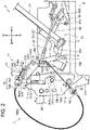
- Fig. 2 is a right side view of the hydraulic lifting/lowering device according to the embodiment.
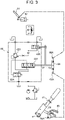
- Fig. 3 is a hydraulic circuit diagram for lifting/lowering according to the embodiment.
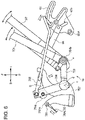
- Fig. 4 is a perspective view of the load detection mechanism according to the embodiment as viewed from the upper left front.
- Fig. 5 is a cross-sectional view of 5A-5A in Fig. 4 .
- Fig. 6 is a right side view for explaining the intermediate link mechanism according to the embodiment.
- the hydraulic lifting/lowering device 5 (tractor 1) includes a hydraulic lifting/lowering drive unit 6 and a mechanical linkage unit 7.
- the lifting/lowering drive unit 6 can lift and lower the three-point link mechanism 3.
- the tiller 4 mounted to the three-point link mechanism 3 is lifted up and down according to the lifting/lowering drive of the three-point link mechanism 3.
- the mechanical linkage unit 7 transmits the lifting/lowering operation amount of the three-point link mechanism 3 to the lifting/lowering drive unit 6. Details of the mechanical linkage unit 7 will be described below.
- the lifting/lowering drive unit 6 has right and left lift arms 61, a lift cylinder 62, a control valve 63, a balance arm 64, a position arm 65, a position arm shaft 65A, a feedback arm shaft 66A, a position lever 67, and a position plate 68.
- the right and left lift arms 61 suspend and support the right and left lower links 3B via the right and left support members.
- the lift arm 61 is hydraulically driven by the lift cylinder 62 so as to be vertically swingable.
- the lift cylinder 62 lifts and lowers the three-point link mechanism 3 via the lift arm 61.
- the lift cylinder 62 is housed in the cylinder case 28.
- the control valve 63 controls the lift cylinder 62.
- the control valve 63 may have a spool 631, a descending valve 632, a relief valve 633, and an unload valve 634, for example.
- the control valve 63 may be connected to the lift cylinder 62 via a drop speed adjusting valve.
- the control valve 63 is housed in the cylinder case 28.
- the spool 631 is always biased in the downward direction D by a biasing means (e.g., a spring).
- the balance arm 64 is swingably connected to an end of the spool 631.
- the position arm shaft 65A is locked and connected to one end of the balance arm 64 via an operation pin, and the feedback arm shaft 66A is locked and connected to the other end of the balance arm 64 via the operation pin.
- the feedback arm shaft 66A is interlocked and connected to the lift arm 61 via a feedback link mechanism (not illustrated).
- the position arm 65 is fixed to the outer end of the position arm shaft 65A.
- the balance arm 64 swings about a locking point of the feedback arm shaft 66A with the operation pin.
- the spool 631 is shifted to the ascending side or the descending side, and the lift arm 61 performs a driving ascending operation or a dead weight descending operation.
- the actuation of the lift arm 61 is transmitted via the feedback link mechanism and converted into rotation of the feedback arm shaft 66A.
- the spool 631 is shifted in the opposite direction via the balance arm 64.
- the spool 631 returns to the neutral position when the feedback arm shaft 66A is rotated to a predetermined rotational position corresponding to the rotational operation position of the position arm 65. As described above, arbitrarily rotating the position arm 65 allows the lift arm 61 to be lifted and lowered to a position corresponding to the position arm 65.
- the position lever 67 sets a control target height of the tiller 4.
- the position lever 67 is disposed on the right side of the driver seat.
- the position lever 67 is disposed so as to be swingable back and forth about a fulcrum a positioned near the rear side of the position arm 65.
- the fulcrum a is a fulcrum common to the control adjustment lever 751 to be described below.
- the position lever 67 is disposed more to the driver seat 272 side (left side) than the control adjustment lever 751.
- the position lever 67 is interlocked and connected to the position arm 65 via a long hole 65h and the position plate 68.
- the position arm 65 Since the spool 631 is biased in the downward direction D by the biasing means, the position arm 65 is rotated and biased clockwise in a side view from the right side (see, e.g., Fig. 2 ). Thus, the rear end of the long hole 65h is engaged with and in contact with the position plate 68.
- the mechanical linkage unit 7 has the load detection mechanism 71, a biasing mechanism 72, a limiting mechanism 73, an operation tool 74, an intermediate link mechanism 75, and a cable 78.
- the vehicle body 2 may have a first cable fixing portion 241 to which a cover portion 78B to be described below is fixed on the intermediate link mechanism 75 side of the rear end of the vehicle body 2 (T/M case 24).
- a support member 91 is fixed to the rear end of the vehicle body 2 (cylinder case 28).
- the support member 91 has: a vertical wall portion 911 connected to the rear portion of the vehicle body 2 (cylinder case 28); a linkage portion 912 which is U-shaped in a top view; an outer wall portion 913 which extends in the upward and downward direction outside the lateral direction of the vertical wall portion 911; a swing support portion 914 which supports a swing member 715 to be described below; and a second cable fixing portion 915 to which the cover portion 78B is fixed.
- the linkage portion 912 has: right and left side portions 912A which extend backward from the vertical wall portion 911; and a rear portion 912B which extends in the lateral direction so as to connect the right and left side portions 912A.
- the load detection mechanism 71 detects the amount of change in traction load via the three-point link mechanism 3, and transmits the amount of change in traction load to the intermediate link mechanism 75 via the cable 78.
- the load detection mechanism 71 has the load detection member 711 and the swing member 715.
- the load detection member 711 detects the amount of change in traction load via the three-point link mechanism 3.
- the load detection member 711 is supported by the support member 91 so as to be swingable and displaceable in the forward and backward direction via a first support shaft 92.
- the load detection member 711 swings back and forth according to a traction load transmitted through the top link 3A.
- the load detection member 711 has: right and left side wall portions 711A; a vertical wall portion 711B to which the side wall portions 711A are fixed; a connection holes 711C formed in the side wall portions 711A; an extension portion 711E which extends forward from the vertical wall portion 711B; and a contact portion 711F which contacts the swing member 715.
- the vertical wall portion 711B is provided on the free end side (upper side) of the load detection member 711.
- the linkage portion 912 of the support member 91 enters between the right and left vertical wall portions 711B.
- the top link 3A or a top link bracket supporting the top link 3A can be connected to the connection hole 711C.
- the extension portion 711E extends from the vertical wall portion 711B toward the forward direction.
- the extension portion 711E is disposed more to the right side than the side wall portion 711A.
- the contact portion 711F extends rightward from the extension portion 711E at the front of the extension portion 711E.
- the swing member 715 swings back and forth according to the back and forth swing of the load detection member 711.
- the swing member 715 is supported by the swing support portion 914 via a second support shaft 914A extending in the lateral direction.
- the swing member 715 is swingable about a fulcrum b passing through the axial center of the second support shaft 914A.
- the swing member 715 swings forward by being pushed forward from the contact portion 711F which moves forward.
- the swing member 715 swings backward by a biasing mechanism (not illustrated). For example, the swing member 715 is pulled backward to a predetermined position by the spring force of the torsion spring mounted to the second support shaft 914A.
- the swing member 715 has a second mounting portion 715A to which a cable 78 (a second connecting portion 782 to be described below) is mounted.
- the second mounting portion 715A is disposed on the free end side.
- the second mounting portion 715A is positioned above the load detection member 711.
- the second mounting portion 715A is positioned more backward than the front end of the lower link 3B.
- the second mounting portion 715A is positioned more backward than a first mounting portion 752A to be described below in a state where no traction load is applied.
- the second mounting portion 715A is positioned more forward than the front end of the top link 3A.
- the second mounting portion 715A is a mounting portion for draft control.
- the biasing mechanism 72 swings and biases the load detection member 711 in a direction (backward) resisting a traction load applied to the load detection member 711.
- the biasing mechanism 72 may be constituted of a spring having elasticity in the forward and backward direction.
- the limiting mechanism 73 limits the back and forth swing range of the load detection member 711.
- the limiting mechanism 73 may be constituted of a through hole 711h, a long hole 912h, a rubber block 73b, and a linkage pin 73p.
- the through hole 711h is formed in the load detection member 711. Specifically, the through holes 711h are formed to face the right and left side wall portions 711A, respectively.
- the long hole 912h is formed in the support member 91 and is long in the forward and backward direction. Specifically, the long hole 912h is formed at a position to face the through hole 711h in each of the right and left side portions 912A of the linkage portion 912.
- the rubber block 73b is fitted in a space between the vertical wall portion 911 of the support member 91 and the linkage portion 912 (side portion 912A and rear portion 912B).
- a long hole 73h having a forward and backward length shorter than that of the long hole 912h of the support member 91 is formed at a position to face the long hole 912h of the support member 91.
- the linkage pin 73p is inserted into each through hole 711h, each long hole 912h, and each long hole 73h.
- the back and forth swing range of the load detection member 711 is limited by the forward and backward length of each long hole 912h of the support member 91.
- the linkage pin 73p of the limiting mechanism 73 collides with the rubber block 73b.
- the load detection member 711 is held in a reference posture extending vertically upward from the first support shaft 92 by the action of the biasing mechanism 72 and the limiting mechanism 73.
- the load detection member 711 swings and displaces forward from the reference posture against the action of the biasing mechanism 72 in conjunction with the increase of the traction load.
- the load detection member 711 swings and displaces backward by the action of the biasing mechanism 72 in conjunction with the decrease of the traction load, and returns to the reference posture.
- the operation tool 74 switches a first state in which the load detection member 711 detects the traction load and a second state in which the load detection member 711 does not detect the traction load.
- the operation tool 74 has a swing plate 741 supported to be swingable in the lateral direction on the support member 91, an operation handle 742 extending in an upward direction U from the swing plate 741, and a contact member 743 extending backward from the swing plate 741.
- the contact member 743 moves between the non-contact position and the contact position. In the non-contact position (first operation position P1), the contact member 743 does not contact the load detection member 711 (vertical wall portion 711B), and the back and forth swing of the load detection member 711 is allowed.
- the contact member 743 comes into contact with the load detection member 711 to prevent the load detection member 711 from swinging back and forth.
- the contact member 743 is sandwiched between the vertical wall portion 711B and the swing plate 741.
- the operation tool 74 swings in the lateral direction about an axis extending in the forward and backward direction.
- the operation tool 74 is selectively positioned and held in either the first operation position P1 (left side) or the second operation position P2 (right side) by a detent mechanism.
- the contact member 743 is positioned at a non-contact position, and the load detection mechanism 71 enters the first state.
- the operation tool 74 is positioned and held at the second operation position P2
- the contact member 743 is positioned at the contact position, and the load detection mechanism 71 enters the second state.
- the operator can perform draft control by moving the operation tool 74 to the first operation position P1.
- the intermediate link mechanism 75 is a mechanical link mechanism. As illustrated in Fig. 2 , the intermediate link mechanism 75 is interlocked and connected to the cable 78 and the lifting/lowering drive unit 6. The intermediate link mechanism 75 transmits a lifting/lowering operation amount according to the amount of change in traction load to the lifting/lowering drive unit 6.
- the intermediate link mechanism 75 has a control adjustment lever 751, a cable connecting arm 752, a linkage plate 753, an adjustment arm 754, and a linkage rod 755.
- the control adjustment lever 751 is a lever for adjusting draft control.
- the control adjustment lever 751 is swingable back and forth about the fulcrum a.
- the cable connecting arm 752 is swingable back and forth about a fulcrum c.
- the cable connecting arm 752 serves as a connection destination on one side of the cable 78.
- the cable connecting arm 752 has the first mounting portion 752A to which the cable 78 is mounted. Specifically, a first connecting portion 781 to be described below is mounted to the first mounting portion 752A.
- the cable connecting arm 752 is provided with a tension spring (not illustrated) for swinging and biasing forward.
- the cable connecting arm 752 has a cam surface S formed convex on a rear end side (a side on the roller 754r side to be described below) of the cable connecting arm 752.
- the linkage plate 753 extends backward from the proximal end (a support shaft extending from the right side surface of the cylinder case 28 in the right direction R) of the control adjustment lever 751.
- the linkage plate 753 is swingable about the fulcrum a.
- the relative positions of the control adjustment lever 751 and the linkage plate 753 are fixed. Therefore, the linkage plate 753 also rotates about the fulcrum a according to the operation of the control adjustment lever 751.
- the adjustment arm 754 is mounted to the tip (rear end) of the linkage plate 753 so as to be swingable back and forth about the fulcrum d.
- a roller 754r as a cam follower is mounted to the adjustment arm 754.
- the adjustment arm 754 is provided with a torsion spring for swinging and biasing the adjustment arm 754 forward.
- the roller 754r abuts on the cam surface S of the cable connecting arm 752 from the rear by the forward bias and swing of the adjustment arm 754 and follows the cam surface S.
- the linkage rod 755 is bridged over the position arm 65 and the cable connecting arm 752.
- the linkage rod 755 transmits the swing and displacement of the adjustment arm 754 according to the following of the cam surface S of the roller 754r to the position arm 65.
- the intermediate link mechanism 75 is positioned more backward than the front end of the lower link 3B of the three-point link mechanism 3.
- at least a portion of the cable connecting arm 752 and at least a portion of the adjustment arm 754 are positioned more backward than the front end of the lower link 3B.
- the intermediate link mechanism 75 (mechanical linkage unit 7) has a sensitivity adjustment mechanism for adjusting operation sensitivity when the lifting/lowering drive unit 6 is interlocked with the swing member 715.
- the sensitivity adjustment mechanism is constituted of the control adjustment lever 751, the cable connecting arm 752, the linkage plate 753, the adjustment arm 754, and the linkage rod 755.
- the linkage plate 753 rotates downward about the fulcrum a (counterclockwise direction in Fig. 6 ) and the fulcrum d displaces downward as the operator operates the control adjustment lever 751 to position the control adjustment lever 751 backward (counterclockwise in Fig. 6 ).
- the distance between the contact point of the roller 754r with respect to the cable connecting arm 752 and the fulcrum c of the cable connecting arm 752 is reduced, and the lever ratio for bringing the adjustment arm 754 into contact with the cable connecting arm 752 by the control adjustment lever 751 is reduced. Therefore, the rotation of the adjustment arm 754 becomes sensitive to the rotation of the cable connecting arm 752.
- the operation sensitivity of the lifting/lowering drive unit 6 becomes sensitive to the swing of the swing member 715, and the responsiveness when the tiller 4A raises is improved when the traction load exceeds a predetermined value.
- the linkage plate 753 rotates upward about the fulcrum a (clockwise in Fig. 6 ), and the fulcrum d displaces upward.
- the distance between the contact point of the roller 754r with respect to the cable connecting arm 752 and the fulcrum c of the cable connecting arm 752 is increased, and the lever ratio for bringing the adjustment arm 754 into contact with the cable connecting arm 752 by the control adjustment lever 751 is increased. Therefore, the rotation of the adjustment arm 754 becomes insensitive to the rotation of the cable connecting arm 752.
- the operation sensitivity of the lifting/lowering drive unit 6 becomes insensitive to the swing of the swing member 715, and the responsiveness when the tiller 4A raises becomes gradual when the traction load exceeds a predetermined value.
- the cable 78 will then be described.
- the cable 78 is interlocked according to the amount of change in traction load detected by the load detection member 711.
- the cable 78 is interlocked and connected to the load detection mechanism 71 and the lifting/lowering drive unit 6. Specifically, the cable 78 is connected to the swing member 715 and the sensitivity adjustment mechanism.
- One end of the cable 78 is connected to the intermediate link mechanism 75 toward the forward direction of the tractor 1.
- the other end of the cable 78 is connected to the load detection member 711 toward the forward direction of the tractor 1.
- the cable 78 has a first connecting portion 781 which is a connecting portion on one side of the cable 78 and a second connecting portion 782 which is a connecting portion on the other side of the cable 78.
- the first connecting portion 781 is connected on the intermediate link mechanism 75 side. Specifically, the first connecting portion 781 is connected to the cable connecting arm 752.
- the second connecting portion 782 is connected on the load detection member 711 (load detection mechanism 71) side.
- the second connecting portion 782 is connected to the swing member 715.
- the second connecting portion 782 is mounted to the second mounting portion 715A at a position higher than the first connecting portion 781.
- the cable 78 is a push-pull cable.
- the cable 78 has an inner cable 78A and a cover portion 78B.
- the inner cable 78A swings according to the swing of the load detection member 711.
- the inner cable 78A can move inside an outer cable 78B3 to be described below.
- the first connecting portion 781 is disposed at one end of the inner cable 78A, and the second connecting portion 782 is disposed at the other end of the inner cable 78A. Therefore, the inner cable 78A is directly connected to the swing member 715.
- the inner cable 78A is directly connected to the cable connecting arm 752.
- the cover portion 78B covers the outside of the inner cable 78A.
- the cover portion 78B has a first fixing portion 78B1 fixed to the first cable fixing portion 241, a second fixing portion 78B2 fixed to the second cable fixing portion 915, and an outer cable 78B3.
- the first fixing portion 78B1 is positioned at the end of the outer cable 78B3 on the intermediate link mechanism 75 side
- the second fixing portion 78B2 is positioned at the end of the outer cable 78B3 on the load detection member 711 side.
- the second fixing portion 78B2 is fixed to the second cable fixing portion 915 at a position higher than the first connecting portion 781.
- the cable 78 has a portion (extension portion E) extending from the second connecting portion 782 toward the backward direction of the tractor 1.
- the cable 78 extends curvedly. Specifically, the cable 78 extends in a C shape or a U shape, in a side view of the tractor 1. Therefore, when the second connecting portion 782 swings forward together with the swing member 715, the first connecting portion 781 is pulled backward, in a side view of the tractor 1. When the second connecting portion 782 swings backward together with the swing member 715, the first connecting portion 781 is pulled forward.
- the lift arm 61 is raised to a position corresponding to the position after the rotation of the position arm 65.
- the displacement of the position arm 65 corresponds to a lifting/lowering operation amount. Therefore, the control valve 63 controls the lift cylinder 62 according to the lifting/lowering operation amount (amount of displacement in the position arm 65).
- the configuration described above enables the cable 78 to carry a part of the transmission path for transmitting the amount of change in traction load from the load detection member 711 to the lifting/lowering drive unit 6. Therefore, the amount of change in the traction load can be transmitted to the lifting/lowering drive unit 6 without increasing the number of plate-like or rod-like link members constituting the mechanical intermediate link mechanism 75. Thus, increasing the number of the link members can be suppressed, and the structure of the mechanical link mechanism can be made less complicated.
- the cable 78 has an extension portion E extending from the second connecting portion 782 toward the backward direction of the tractor 1.
- One end of the cable 78 is connected to the intermediate link mechanism 75 toward the forward direction, and the other end of the cable 78 is connected to the load detection member 711 toward the forward direction.
- an operator positioned in the rear of the tractor 1 can recognize the connecting portions (the first connecting portion 781 and the second connecting portion 782) by tracing the cable 78 from the rear of the tractor.
- the operator can easily perform the maintenance work such as inspection and replacement work of the cable 78.
- the operator can easily carry the second connecting portion 782 to the second mounting portion 715A by gripping the extension portion E so that the second connecting portion 782 is positioned more to the front side of the operator than the extension portion E. Therefore, the operator can easily mount the second connecting portion 782 and easily perform the maintenance work.
- the cable 78 extends curvedly so that when the second connecting portion 782 swings forward with the swing member 715, the first connecting portion 781 is pulled backward, and when the second connecting portion 782 swings backward with the swing member 715, the first connecting portion 781 is pulled forward, in a side view of the tractor 1.
- the second connecting portion 782 is mounted to the first mounting portion 752A at a position higher than the first connecting portion 781. The operator can carry the second connecting portion 782 to the mounting portion without causing the operator to move significantly by bending the cable 78 in the maintenance work.
- the second connecting portion 782 since the second connecting portion 782 is positioned at a position higher than the first connecting portion 781, the second connecting portion can be mounted at a position close to the height of the operator's eye line. The operator can easily perform the maintenance work.
- the tractor 1 has cable fixing portions (first cable fixing portion 241 and second cable fixing portion 915). Fixing the cover portion 78B by the cable fixing portions allows the inner cable 78A to be stably swung.
- the mechanical linkage unit 7 can accurately transmit the lifting/lowering operation amount according to the amount of change in traction load to the lifting/lowering drive unit 6, so that a high quality draft control can be executed.
- the cable 78 is connected to the swing member 715 and the sensitivity adjustment mechanism.
- the number of link members connecting the swing member 715 and the sensitivity adjustment mechanism can be reduced, and the structure of the hydraulic lifting/lowering device 5 is hardly complicated.
- At least a portion of the intermediate link mechanism 75 is positioned more backward than the front end of the lower link 3B.
- the intermediate link mechanism 75 can be easily confirmed from the rear of the tractor 1, so that the maintainability can be improved.
- the second mounting portion 715A is positioned above the load detection member 711.
- the second mounting portion 715A can be visually recognized above the load detection member 711, and the load detection member 711 is hardly overlapped with the second mounting portion 715A.
- the second connecting portion and the mounting portion are easily confirmed from the rear of the tractor 1, and the second connecting portion 782 is easily mounted and removed. Therefore, the switching work can be easily performed.
- a space including the second mounting portion 715A is not required in front of the load detection member 711.
- the second mounting portion 715A is positioned more backward than the front end of the lower link 3B. Since the distance from the rear of the tractor 1 to the second mounting portion 715A is closer than that to the front end of the lower link 3B, the second connecting portion 782 is easily mounted and removed from the rear of the tractor 1. Therefore, the maintenance work can be easily performed.
- the second mounting portion 715A is positioned more backward than the first mounting portion 752A in a state where no traction load is applied. Since the distance from the rear of the tractor 1 to the second mounting portion 715A is closer than that to the first mounting portion 752A, the second connecting portion 782 is easily mounted and removed from the rear of the tractor 1. Therefore, the maintenance work can be easily performed.
- FIG. 7 is a right side view of a hydraulic lifting/lowering device according to the modified example.
- Fig. 8 is a perspective view of a load detection mechanism according to the modified example as viewed from the upper right rear.
- Fig. 9 is a rear view of the load detection mechanism according to the modified example as viewed from the rear.
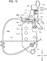
- Fig. 10 is a right side view of the load detection mechanism according to the modified example.
- Fig. 11 is a right side view of the load detection mechanism according to the modified example. Note that the same structure as described above will not be explained.
- the mechanical linkage unit 7 in the modified example has an amplification swing member 77.
- the amplification swing member 77 is supported by the load detection member 711 so as to be swingable. Specifically, the amplification swing member 77 is supported by the load detection member 711 via a third support shaft 773 extending in the lateral direction. Thus, the amplification swing member 77 is swingable about a fulcrum f.
- the upper portion of the amplification swing member 77 is positioned above the fulcrum f, and the lower portion of the amplification swing member 77 is positioned below the fulcrum f.
- the amplification swing member 77 swings back and forth according to the back and forth swing of the load detection member 711.
- the amount of change in traction load is amplified by the back and forth swing of the amplification swing member 77.
- a contact roller 775 rotatable about a fulcrum of a fourth support shaft 774 is mounted to the amplification swing member 77 via the fourth support shaft 774 extending in the lateral direction. Specifically, the contact roller 775 is mounted to a lower portion of the amplification swing member 77.
- the contact roller 775 contacts the swing member 715.
- the load detection mechanism 71 has an amplification contact portion 711G in contact with the amplification swing member 77.
- the amplification contact portion 711G extends outward in the lateral direction (in the present modification, from the right side wall portion 711A in the right direction L) from the side wall portion 711A.
- the load detection mechanism 71 does not have an extension portion 711E and a contact portion 711F, which differs from the first embodiment.
- the operation tool 74 has a receiving portion 745 for receiving the amplification swing member 77.
- the receiving portion 745 has a receiving roller 745A for receiving the amplification swing member 77 and a support portion 745B for supporting the receiving roller 745A.
- the operation tool 74 switches a first state, a second state and a third state.
- the first state is a state in which the load detection member 711 detects a traction load.
- the lifting/lowering operation amount according to the amount of change in traction load which is not amplified by the back and forth swing of the amplification swing member 77 is transmitted to the lifting/lowering drive unit 6.
- the second state is a state in which the load detection member 711 does not detect a traction load.
- the third state is a state in which the lifting/lowering operation amount according to the amount of change in traction load amplified by the back and forth swing of the amplification swing member 77 is transmitted to the lifting/lowering drive unit. Therefore, in the third state, the amount of change in traction load detected by the load detection member 711 is amplified.
- the operation tool 74 is selectively positioned and held in either the first operation position P1 (right side), the second operation position P2 (left side), and a third operation position (center).
- the contact member 743 is positioned at a non-contact position.
- the receiving portion 745 does not contact the amplification swing member 77.
- the load detection mechanism 71 enters the first state.
- the contact member 743 is positioned at a contact position, and the load detection mechanism 71 enters the second state.
- the contact member 743 is positioned at a non-contact position.
- the receiving portion 745 contacts the amplification swing member 77.
- the load detection mechanism 71 enters the third state.
- the amplification contact portion 711G moves forward.
- the forward movement of the amplification contact portion 711G allows the amplification swing member 77 to be pushed forward. Since the receiving portion 745 (the receiving roller 745A) does not contact the amplification swing member 77, the amplification swing member 77 is pushed forward only by an amount according to the swing of the load detection member 711.
- the contact roller 775 coming into contact with the swing member 715 moves forward by the amount that the amplification swing member 77 is pushed forward, and the swing member 715 swings forward according to the moving amount of the contact roller 775.
- the second connecting portion 782 of the cable 78 swings forward together with the swing member 715, the first connecting portion 781 is pulled backward.
- the amplification contact portion 711G moves forward and the amplification swing member 77 is pushed forward. Since the receiving portion 745 (the receiving roller 745A) comes into contact with the amplification swing member 77, the upper portion of the amplification swing member 77 is not pushed forward, while the lower portion of the amplification swing member 77 is pushed forward. Consequently, in Fig. 11 , the amplification swing member 77 swings counterclockwise about the fulcrum f. Therefore, the amplification swing member 77 swings relative to the load detection member 711.
- the lower portion of the amplification swing member 77 specifically, the contact roller 775 moves forward by the amount of swing of the amplification swing member 77 in addition to the amount of swing of the load detection member 711. Since the contact roller 775 moves forward by the amount that the amplification swing member 77 is pushed forward, in the third state, the swing member 715 swings further forward than in the first state even under the same traction load as in the first state. Therefore, the swing of the amplification swing member 77 increases the amount of change in traction load.
- the amount of change in traction load is amplified by the back and forth swing of the amplification swing member 77.
- the tiller 4A can be quickly lifted and lowered according to the change of the traction load. Consequently, even when the traction load rapidly increases, the engine stall caused by the increase of the traction load can be avoided.
- the third state in which a lifting/lowering operation amount according to the amount of change in traction load amplified by the back and forth swing of the amplification swing member 77 is transmitted to the lifting/lowering drive unit 6, and the first state in which a lifting/lowering operation amount according to the amount of change in traction load not amplified by the back and forth swing of the amplification swing member 77 is transmitted to the lifting/lowering drive unit 6, are switched.
- the operator can lift and lower the three-point link mechanism 3 according to the condition of the soil in which the traction work is to be performed (e.g., hardness of soil, and content ratio of stone, rock and wood).
- the vehicle body 2 may have a fourth cable fixing portion 244 to which the cover portion 78B is fixed.
- the front end of the fourth cable fixing portion 244 is supported, and the fourth cable fixing portion 244 may extend backward.
- the rear end of the fourth cable fixing portion 244 may be provided with a spiral portion extending in a spiral shape.
- the cover portion 78B may be able to insert into the spiral portion.
- the cover portion 78B may be fixed by inserting the cover portion 78B into the spiral portion.
- the cover portion 78B is fixed at the three points of the first fixing portion 78B1, the second fixing portion 78B2, and the fourth cable fixing portion 244, so that the cover portion 78B can be prevented from swinging due to, for example, vibration caused by traveling.
- the vibration of the first fixing portion 78B1 and the second fixing portion 78B2 is suppressed, the load applied to the first mounting portion 752A and the second mounting portion 715A is reduced, and the damage of the first mounting portion 752A and the second mounting portion 715A can be reduced.
- the tractor 1 may be replaceable with a traction type tiller 4A and a rotary tiller 4B.
- a tractor 1 including the rotary tiller 4B will then be described mainly with reference to Figs. 12 and 13 .
- Fig. 12 is a right side view of the tractor according to the second embodiment.
- Fig. 13 is a right side view of a hydraulic lifting/lowering device according to the second embodiment. Note that the same structure as described above will not be described.
- the rotary tiller 4B can be mounted to the three-point link mechanism 3.
- the rotary tiller 4B can be mounted to and removed from the tractor 1 (three-point link mechanism 3) by mounting and removing the rotary tiller 4B via a hitch device 8.
- the hitch device 8 is provided at the rear of the three-point link mechanism 3.
- the hitch device 8 is used to connect the tiller 4 (rotary tiller 4B).
- the hitch device 8 has a linkage member 81 and a third cable fixing portion 83.
- the linkage member 81 swings back and forth together with a swing arm 45 to be described below. Therefore, the linkage member 81 swings back and forth according to the amount of change in tilling depth.
- the linkage member 81 has a third mounting portion 813 to which the second connecting portion 782 is mounted.
- the third mounting portion 813 is a mounting portion for automatic tilling depth control.
- the second lifting/lowering operation amount according to the amount of change in tilling depth is selected as the lifting/lowering operation amount transmitted to the lifting/lowering drive unit 6, the second connecting portion 782 is mounted to the third mounting portion 813.
- the third mounting portion 813 is positioned more backward than the rear end of the top link 3A.
- the third cable fixing portion 83 has the cover portion 78B fixed thereto.
- a bracket 35 for supporting the top link 3A is mounted to the load detection member 711.
- the top link 3A is shorter than the top link 3A in
- the rotary tiller 4B has: a rotor portion 41; a tilling cover 42 covering the rotor portion 41 from above; a ground body (rear cover) 43 for detecting the amount of change in the tilling depth of the rotary tiller 4B; a transmission case portion 44; a swing arm 45 provided on the transmission case portion 44 so as to be swingable back and forth; and a linkage link 46 bridged over the lower free end of the swing arm 45 and the ground body 43.
- the ground body 43 is a rear cover for preventing scattering of soil during tilling and averaging tilling traces.
- the ground body 43 is provided at the rear end of the tilling cover 42.
- the ground body 43 is vertically swingable about a fulcrum e.
- the linkage member 81 is rotatably provided on the rear of the three-point link mechanism 3 with the central portion of the linkage member 81 as a fulcrum.
- the rotary tiller 4B is connected to the three-point link mechanism 3 via the hitch device 8
- one end of the linkage member 81 is engaged and connected to an engaging recess (not illustrated) formed in the swing arm 45.
- the linkage member 81 rotates in accordance with the swing of the swing arm 45.
- the third mounting portion 813 is provided at the other end of the linkage member 81.
- the third mounting portion 813 has a second connecting portion 782 of the cable 78 mounted thereto.
- the ground body 43 and the control valve 63 are linked via the cable 78.
- the automatic tilling depth control will then be described.
- the ground body 43 is lifted and swung accordingly.
- the linkage link 46 moves forward
- the swing arm 45 swings forward
- the linkage member 81 rotates counterclockwise.
- the rotation of the linkage member 81 pulls the second connecting portion 782 of the cable 78 backward and also pulls the first connecting portion 781 backward.
- the cable connecting arm 752 rotates backward about the fulcrum c and the position arm 65 rotates backward about the position arm shaft 65A, as in the draft control.
- the lift arm 61 is raised to a position corresponding to the position after the rotation of the position arm 65, and the rotary tiller 4B is also raised.
- the linkage rod 755 is pushed forward together with the adjustment arm 754, and the position arm 65 rotates forward about the position arm shaft 65A.
- the lift arm 61 is lowered to a position corresponding to the position after the rotation of the position arm 65, and the rotary tiller 4B also is lowered.
- the lowering operation is stopped and the original tilling depth is returned.
- the operation tool 74 When automatic tilling depth control is performed, the operation tool 74 is moved to the second operation position P2. Thus, the load detection mechanism 71 enters the second state, and the load detection member 711 does not swing back and forth. Therefore, the amount of change in tilling depth can be accurately detected.
- the above configuration switches the connection destination of the second connecting portion 782 of the cable 78, whereby either one of the first lifting/lowering operation amount according to the amount of change in traction load and the second lifting/lowering operation amount according to the amount of change in tilling depth is selected as the lifting/lowering operation amount transmitted to the lifting/lowering drive unit 6.
- the cable 78 can selectively transmit the amount of change in traction load and the amount of change in tilling depth.
- the first lifting/lowering operation amount is transmitted to the lifting/lowering drive unit 6 as the lifting/lowering operation amount.
- the lifting/lowering drive unit 6 controls the lift cylinder 62 according to the first lifting/lowering operation amount (i.e., the amount of change in traction load). Therefore, the traction type tiller 4A can be automatically lifted and lowered according to the traction load in the tilling work.
- the second lifting/lowering operation amount is transmitted to the lifting/lowering drive unit 6 as the lifting/lowering operation amount.
- the lifting/lowering drive unit 6 controls the lift cylinder 62 according to the second lifting/lowering operation amount (i.e., the amount of change in tilling depth). Therefore, the rotary tiller 4B can be automatically lifted and lowered according to the tilling depth in the tilling work.
- the intermediate link mechanism 75 connected to the first connecting portion 781 is a link mechanism common to both draft control and automatic tilling depth control. Therefore, since similar functions of the draft control and the automatic tilling depth control can be combined into one link mechanism, the structure of the hydraulic lifting/lowering device 5 can be made less complicated.
- the second mounting portion 715A is positioned more forward than the front end of the top link 3A.
- the third mounting portion 813 is positioned more backward than the rear end of the top link.
- the cable 78 is more flexible than a plate-like or rod-like link member used in a general mechanical link mechanism. Therefore, the degree of freedom in the disposition of the connection destination of the cable 78 is increased, and the structure of the hydraulic lifting/lowering device 5 can be made less complicated.
- connection destination of the cable 78 having a wide movable range by the flexibility allows the switching work between the draft control and the automatic tilling depth control to be easily performed.
- the cable 78 has an extension portion E extending from the second connecting portion 782 toward the backward direction of the tractor 1.
- the second connecting portion 782 is mounted to the second mounting portion 715A toward the forward direction.
- an operator positioned in the rear of the tractor 1 can easily carry the second connecting portion 782 to the second mounting portion 715A by gripping the extension portion E so that the second connecting portion 782 is positioned more to the front side of the operator than the extension portion E. Therefore, the operator can easily mount the second connecting portion 782, and can easily perform the switching work to the draft control.
- the cable 78 extends curvedly so that when the second connecting portion 782 swings forward with the swing member 715, the first connecting portion 781 is pulled backward, and when the second connecting portion 782 swings backward with the swing member 715, the first connecting portion 781 is pulled forward, in a side view of the tractor 1.
- the second connecting portion 782 is mounted to the first mounting portion 752A at a position higher than the first connecting portion 781. The operator can carry the second connecting portion 782 to the mounting portion without causing the operator to move significantly by bending the cable 78 in the maintenance work.
- the second connecting portion 782 since the second connecting portion 782 is positioned at a position higher than the first connecting portion 781, the second connecting portion can be mounted at a position close to the height of the operator's eye line. The operator can easily perform the switching work to the draft control.
- the tractor 1 has cable fixing portions (first cable fixing portion 241, second cable fixing portion 915, and third cable fixing portion 83). Fixing the cover portion 78B by the cable fixing portions allows the inner cable 78A to be stably swung. Thus, the mechanical linkage unit 7 can accurately transmit the lifting/lowering operation amount according to the amount of change in traction load to the lifting/lowering drive unit 6, so that a high quality draft control can be executed.
- the cable 78 is connected to the swing member 715 and the sensitivity adjustment mechanism.
- the number of link members connecting the swing member 715 and the sensitivity adjustment mechanism can be reduced, and the structure of the hydraulic lifting/lowering device 5 is hardly complicated.
- At least a portion of the intermediate link mechanism 75 is positioned more backward than the front end of the lower link 3B.
- the intermediate link mechanism 75 can be easily confirmed from the rear of the tractor 1, so that the maintainability can be improved.
- the second mounting portion 715A is positioned above the load detection member 711.
- the second mounting portion 715A can be visually recognized above the load detection member 711, and the load detection member 711 is hardly overlapped with the second mounting portion 715A.
- the second connecting portion and the mounting portion are easily confirmed from the rear of the tractor 1, and the second connecting portion 782 is easily mounted and removed. Therefore, the switching work can be easily performed.
- a space including the second mounting portion 715A is not required in front of the load detection member 711.
- the second mounting portion 715A is positioned more backward than the front end of the lower link 3B. Since the distance from the rear of the tractor 1 to the second mounting portion 715A is closer than that to the front end of the lower link 3B, the second connecting portion 782 is easily mounted and removed from the rear of the tractor 1. Therefore, the switching work can be easily performed.
- the hitch device 8 has a linkage member 81 for swinging back and forth according to the amount of change in tilling depth.
- the linkage member 81 has a third mounting portion 813 to which the second connecting portion 782 is mounted.
- the second mounting portion 715A is positioned more backward than the first mounting portion 752A in a state where no traction load is applied. Since the distance from the rear of the tractor 1 to the second mounting portion 715A is closer than that to the first mounting portion 752A, the second connecting portion 782 is easily mounted and removed from the rear of the tractor 1. Therefore, the switching work can be easily performed.
- the configuration of the tractor 1 can be variously changed.
- the tractor 1 may be of a semi-crawler specification including right and left crawlers in place of the right and left rear wheels 25B.
- the tractor 1 may be of a full-crawler specification including right and left crawlers in place of the right and left wheels 25.
- the tractor 1 may be of an electric specification including an electric motor in place of the engine 22.
- the tractor 1 may be of a hybrid specification including the engine 22 and an electric motor.
- the cable 78 may have a portion extending laterally of the tractor 1.
- the extension portion E may extend laterally in a back view of the tractor 1 (as viewed from the rear of the tractor 1).
- An operator positioned on the side of the tractor 1 can easily carry the second connecting portion 782 to the second mounting portion 715A by gripping the extension portion E so that the second connecting portion 782 is positioned more to the front side of the operator than the extension portion E. Therefore, the operator can easily mount the second connecting portion 782 and can easily perform the maintenance work and/or the switching work to the draft control.
- the swing member is provided which swings back and forth according to the back and forth swing of the load detection member 711, and the swing member 715 is provided with a second mounting portion 715A to which the cable 78 is mounted, but the embodiment is not limited thereto.
- the load detection member 711 may be provided with the second mounting portion 715A.
- the first connecting portion 781 when the second connecting portion 782 swings forward together with the swing member 715, the first connecting portion 781 is pulled backward, and when the second connecting portion 782 swings backward together with the swing member 715, the first connecting portion 781 is pulled forward, in a side view of the tractor 1, but the embodiment is not limited thereto.
- the first connecting portion 781 may be pulled forward when the second connecting portion 782 swings forward, and the first connecting portion 781 may be pulled backward when the second connecting portion 782 swings backward, by a configuration for reversing the movement of the swing member 715.
- the linkage member 81 is engaged with and connected to the engaging recess of the swing arm 45, and is rotatable, but is not limited thereto.
- the linkage link 46 may be connected to the lower free end of the linkage member 81.
- the linkage member 81 may be swung back and forth by the linkage link 46 without the swing arm 45.
- the tractor 1 in the second embodiment may have the load detection mechanism 71 in the modified example of the first embodiment.
- the tractor 1 may have a member other than the member described above, or may have only a portion of the member described above. Therefore, for example, the lifting/lowering drive unit 6 and the mechanical linkage unit 7 may have members other than the members described above, or may have only a portion of the members described above.
Landscapes
- Life Sciences & Earth Sciences (AREA)
- Engineering & Computer Science (AREA)
- Mechanical Engineering (AREA)
- Soil Sciences (AREA)
- Environmental Sciences (AREA)
- Lifting Devices For Agricultural Implements (AREA)
Abstract
Description
- The present disclosure relates to a tractor.
- Conventionally, there has been known a tractor which includes a three-point link mechanism to which a tiller can be mounted, a hydraulic lifting/lowering drive unit for lifting and lowering the three-point link mechanism, and a mechanical linkage unit for transmitting the lifting/lowering operation amount of the three-point link mechanism to the lifting/lowering drive unit (see, e.g., Patent Literature 1).
- The mechanical linkage unit has a load detection member for detecting an amount of change in traction load via the three-point link mechanism, and a mechanical link mechanism for transmitting a lifting/lowering operation amount according to the amount of change in traction load to the lifting/lowering drive unit. Thus, the lifting/lowering drive unit lifts and lowers the three-point link mechanism to enable the tiller mounted to the three-point link mechanism to perform draft control which automatically lifts up and down according to the traction load.
- Patent Literature 1:
JP 2006-109802 A - In general, since there is a distance from the load detection member to the lifting/lowering drive unit, the mechanical link mechanism transmits an amount of change in traction load to the lifting/lowering drive unit by interlocking and connecting a plurality of plate-shaped or rodshaped link members.
- Since a plurality of link members is used in the mechanical link mechanism, the structure of the mechanical link mechanism is easily complicated. As the mechanical link mechanism becomes more complicated, the maintenance takes more time and chattering is more likely to occur due to the large number of link members.
- Accordingly, it is an object of the present invention to provide a tractor in which the structure of a mechanical link mechanism is hardly complicated.
- A tractor according to an embodiment including: a three-point link mechanism to which a tiller is mountable; a hydraulic lifting/lowering drive unit that lifts and lowers the three-point link mechanism; and a mechanical linkage unit that transmits a lifting/lowering operation amount of the three-point link mechanism to the lifting/lowering drive unit. The mechanical linkage unit has: a load detection member that detects an amount of change in traction load via the three-point link mechanism; a cable that interlocks according to the amount of change in the traction load detected by the load detection member; and a mechanical link mechanism interlocked and connected to the cable and the lifting/lowering drive unit, the mechanical link mechanism transmitting the lifting/lowering operation amount according to the amount of change in the traction load to the lifting/lowering drive unit.
-
- Fig. 1
- is a right side view of a tractor according to a first embodiment.
- Fig. 2
- is a right side view of a hydraulic lifting/lowering device according to the first embodiment.
- Fig. 3
- is a hydraulic circuit diagram for lifting/lowering according to the first embodiment.
- Fig. 4
- is a perspective view of a load detection mechanism according to the first embodiment as viewed from the upper left front.
- Fig. 5
- is a cross-sectional view of 5A-5A in
Fig. 4 . - Fig. 6
- is a right side view for explaining an intermediate link mechanism according to the first embodiment.
- Fig. 7
- is a right side view of a hydraulic lifting/lowering device according to a modified example.
- Fig. 8
- is a perspective view of a load detection mechanism according to the modified example as viewed from the upper right rear.
- Fig. 9
- is a rear view of the load detection mechanism according to the modified example as viewed from the rear.
- Fig. 10
- is a right side view of the load detection mechanism according to the modified example.
- Fig. 11
- is a right side view of the load detection mechanism according to the modified example.
- Fig. 12
- is a right side view of a tractor according to a second embodiment.
- Fig. 13
- is a right side view of a hydraulic lifting/lowering device according to the second embodiment.
- A tractor according to an embodiment including: a three-point link mechanism to which a tiller is mountable; a hydraulic lifting/lowering drive unit that lifts and lowers the three-point link mechanism; and a mechanical linkage unit that transmits a lifting/lowering operation amount of the three-point link mechanism to the lifting/lowering drive unit. The mechanical linkage unit has: a load detection member that detects an amount of change in traction load via the three-point link mechanism; a cable that interlocks according to the amount of change in the traction load detected by the load detection member; and a mechanical link mechanism interlocked and connected to the cable and the lifting/lowering drive unit, the mechanical link mechanism transmitting the lifting/lowering operation amount according to the amount of change in the traction load to the lifting/lowering drive unit.
- Thus, in the mechanical linkage unit, the cable can carry a part of the transmission path for transmitting the amount of change in traction load from the load detection member to the lifting/lowering drive unit. Therefore, the amount of change in traction load can be transmitted to the lifting/lowering drive unit without increasing the number of plate-like or rod-like link members constituting the mechanical link mechanism. Thus, increasing the number of the link members can be suppressed, and the structure of the mechanical link mechanism can be made less complicated.
- According to a preferred embodiment, the cable can have: a first connecting portion connected on the mechanical link mechanism side and a second connecting portion connected on the load detection member side, and a portion extending from the second connecting portion toward a backward direction of the tractor. One end of the cable can be connected to the mechanical link mechanism toward a forward direction of the tractor; and another end of the cable can be connected to the load detection member toward a forward direction of the tractor.
- Thus, an operator positioned in the rear of the tractor can recognize each connecting portion by tracing the cable from the rear of the tractor. Therefore, the operator can easily perform the maintenance work such as cable inspection and replacement work.
- According to a preferred embodiment, the cable can have: a first connecting portion connected on the mechanical link mechanism side, and a second connecting portion connected on the load detection member side. The tractor can have: a mounting portion to which the second connecting portion is mounted, and a swing member that swings back and forth according to a back and forth swing of the load detection member. The cable can extend curvedly so that when the second connecting portion swings forward together with the swing member, the first connecting portion is pulled backward, and when the second connecting portion swings backward together with the swing member, the first connecting portion is pulled forward, in a side view of the tractor. The second connecting portion can be mounted to the mounting portion at a position higher than the first connecting portion.
- The operator can carry the second connecting portion to the mounting portion without causing the operator to move significantly by bending the cable in the maintenance work. In addition, since the second connecting portion is positioned at a position higher than the first connecting portion, the second connecting portion can be mounted at a position close to the height of the operator's eye line. The operator can easily perform the maintenance work.
- According to a preferred embodiment, the cable can have: an inner cable that swings according to a back and forth swing of the swing member; a cover portion that covers an outside of the inner cable; and a cable fixing portion that fixes the cover portion.
- Fixing the cover portion by the cable fixing portion allows the swinging path of the inner cable to be fixed, and the inner cable to be stably swung according to the back and forth swing of the swing member. Thus, the mechanical linkage unit can accurately transmit the lifting/lowering operation amount according to the amount of change in traction load to the lifting/lowering drive unit, so that a high quality draft control can be executed.
- According to a preferred embodiment, the tractor can have a swing member that swings back and forth according to a back and forth swing of the load detection member. The mechanical linkage unit can have a sensitivity adjustment mechanism that adjusts an operation sensitivity when the lifting/lowering drive unit interlocks with the swing member. The cable can ve connected to the swing member and the sensitivity adjustment mechanism.
- Since the cable directly connects the swing member and the sensitivity adjustment mechanism, the number of link members connecting the swing member and the sensitivity adjustment mechanism can be reduced, and the structure of the hydraulic lifting/lowering device is hardly complicated.
- According to a preferred embodiment, at least a portion of the mechanical link mechanism can be positioned more backward than the front end of the lower link of the three-point link mechanism. The mechanical link mechanism can be easily confirmed from the rear of the tractor, so that the maintainability can be improved.
- According to a preferred embodiment, the cable can have: a first connecting portion connected on the mechanical link mechanism side, and a second connecting portion connected on the load detection member side. A mounting portion to which the second connecting portion can be mounted is positioned above the load detection member.
- Thus, the second connecting portion and the mounting portion are easily confirmed from the rear of the tractor, and the second connecting portion is easily mounted and removed. Therefore, the maintenance work can be easily performed. A space including the mounting portion of the second connecting portion is not required in front of the load detection member.
- According to a preferred embodiment, the cable can have: a first connecting portion connected on the mechanical link mechanism side, and a second connecting portion connected on the load detection member side. The mechanical linkage unit can include: a first mounting portion to which the first connecting portion is mounted, and a second mounting portion to which the second connecting portion is mounted. The second mounting portion can be positioned more backward than the first mounting portion in a state where the traction load is not applied.
- Thus, since the distance from the rear of the tractor to the second mounting portion is closer than that to the first mounting portion, the second connecting portion is easily mounted and removed from the rear of the tractor. Therefore, the maintenance work can be easily performed.
- According to a preferred embodiment, the mechanical linkage unit can have an amplification swing member that is supported by the load detection member so as to be swingable and swings back and forth according to a back and forth swing of the load detection member. The amount of change in the traction load can be amplified by the back and forth swing of the amplification swing member.
- Thus, the tiller can be quickly lifted and lowered according to the change of the traction load. Consequently, even when the traction load rapidly increases, the engine stall caused by the increase of the traction load can be avoided.
- According to a preferred embodiment, a state in which the lifting/lowering operation amount according to the amount of change in the traction load amplified by the back and forth swing of the amplification swing member is transmitted to the lifting/lowering drive unit and a state in which the lifting/lowering operation amount according to the amount of change in the traction load not amplified by the back and forth swing of the amplification swing member is transmitted to the lifting/lowering drive unit can be switched.
- Thus, the operator can lift and lower the three-point link mechanism according to the condition of the soil in which the traction work is to be performed (e.g., hardness of soil, and content ratio of stone, rock and wood).
- According to a preferred embodiment, a first connecting portion which is a connecting portion on one side of the cable can be connected to the mechanical link mechanism. The cable can selectively transmit the amount of change in the traction load and an amount of change in tilling depth A connection destination of a second connecting portion which is a connecting portion on another side of the cable is switched, whereby either one of a first lifting/lowering operation amount according to the amount of change in the traction load and a second lifting/lowering operation amount according to the amount of change in the tilling depth is selected as the lifting/lowering operation amount transmitted to the lifting/lowering drive unit.
- In order to switch the connection destination of the second connecting portion of the cable, the mechanical link mechanism connected to the first connecting portion of the cable is a link mechanism common to both draft control and automatic tilling depth control. Therefore, since similar functions of the draft control and the automatic tilling depth control can be combined into one link mechanism, the structure of the hydraulic lifting/lowering device can be made less complicated. The cable is more flexible than a plate-like or rod-like link member used in a general mechanical link mechanism. Therefore, the degree of freedom in the disposition of the connection destination of the cable is increased, and the structure of the hydraulic lifting/lowering device can be made less complicated. In addition, switching the connection destination of the cable having a wide movable range by the flexibility allows the switching work between the draft control and the automatic tilling depth control to be easily performed. According to a preferred embodiment, the tractor can have: a mounting portion for draft control to which the second connecting portion is mounted when the first lifting/lowering operation amount is selected as the lifting/lowering operation amount; and a mounting portion for automatic tilling depth control to which the second connecting portion is mounted when the second lifting/lowering operation amount is selected as the lifting/lowering operation amount. The mounting portion for draft control can be positioned more forward than a front end of a top link of the three-point link mechanism. The mounting portion for automatic tilling depth control can be positioned more backward than a rear end of the top link.
- When the operator performs the switching work between the draft control and the automatic tilling depth control, the operator can work between the front end and the rear end of the top link in a side view of the tractor, and can easily perform the switching work between the draft control and the automatic tilling depth control.
- According to a preferred embodiment, the tractor can have a mounting portion to which the second connecting portion is mounted when the first lifting/lowering operation amount is selected as the lifting/lowering operation amount. The cable can have a portion extending from the second connecting portion toward a backward direction of the tractor. The second connecting portion can be mounted to the mounting portion toward a forward direction of the tractor.
- When selecting the first lifting/lowering operation amount as the lifting/lowering operation amount, that is, when switching to the draft control, the operator positioned at the rear of the tractor can easily carry the second connecting portion to the mounting portion by gripping the portion (extension portion) extending toward the backward direction of the tractor so that the second connecting portion is positioned more to the front side of the operator than the extension portion. Therefore, the operator can easily perform the switching work to the draft control.
- According to a preferred embodiment, the tractor can have: a load detection member that swings back and forth according to the traction load transmitted through a top link of the three-point link mechanism, a mounting portion to which the second connecting portion is mounted, and a swing member that swings back and forth according to a back and forth swing of the load detection member. The cable can extend curvedly so that when the second connecting portion swings forward together with the swing member, the first connecting portion is pulled backward, and when the second connecting portion swings backward together with the swing member, the first connecting portion is pulled forward, in a side view of the tractor. The second connecting portion can be mounted to the mounting portion at a position higher than the first connecting portion.
- When switching to the draft control, the operator can carry the second connecting portion to the mounting portion without causing the operator to move significantly by bending the cable. In addition, since the second connecting portion is positioned at a position higher than the first connecting portion, the second connecting portion can be mounted at a position close to the height of the operator's eye line. The operator can easily perform the switching work to the draft control.
- According to a preferred embodiment, the cable can have: an inner cable that swings according to a back and forth swing of the swing member; a cover portion that covers an outside of the inner cable; and a cable fixing portion that fixes the cover portion.
- Fixing the cover portion by the cable fixing portion allows the swinging path of the inner cable to be fixed, and the inner cable to be stably swung according to the back and forth swing of the swing member. Thus, the mechanical linkage unit can accurately transmit the lifting/lowering operation amount according to the amount of change in traction load to the lifting/lowering drive unit, so that a high quality draft control can be executed.
- According to a preferred embodiment, the tractor can have: a load detection member that swings back and forth according to the traction load transmitted through a top link of the three-point link mechanism; and a swing member that swings back and forth according to a back and forth swing of the load detection member. The mechanical linkage unit can have a sensitivity adjustment mechanism that adjusts an operation sensitivity when the lifting/lowering drive unit interlocks with the swing member. The cable can be connected to the swing member and the sensitivity adjustment mechanism.
- Since the cable directly connects the swing member and the sensitivity adjustment mechanism, the number of link members connecting the swing member and the sensitivity adjustment mechanism can be reduced, and the structure of the hydraulic lifting/lowering device is hardly complicated.
- According to a preferred embodiment, at least a portion of the mechanical link mechanism can be positioned more backward than a front end of a lower link of the three-point link mechanism. The mechanical link mechanism can be easily confirmed from the rear of the tractor, so that the maintainability can be improved.
- According to a preferred embodiment, the tractor can have: a load detection member that swings back and forth according to the traction load transmitted through a top link of the three-point link mechanism, and a mounting portion to which the second connecting portion is mounted when the first lifting/lowering operation amount is selected as the lifting/lowering operation amount. The mounting portion can be positioned above the load detection member.
- Thus, when the automatic tilling depth control is switched to the draft control, the second connecting portion and the mounting portion is easily confirmed from the rear of the tractor, and the connection destination of the second connecting portion is easily switched. Therefore, the switching work can be easily performed.
- According to a preferred embodiment, the tractor can have a hitch device for connecting the tiller at a rear of the three-point link mechanism. The hitch device can have a linkage member that swings back and forth according to the amount of change in tilling depth. The linkage member can have a mounting portion to which the second connecting portion is mounted when the second lifting/lowering operation amount is selected as the lifting/lowering operation amount.
- Thus, since the second connecting portion of the cable is directly mounted to the linkage member of the hitch device, the number of members for transmitting the amount of change in tilling depth to the cable can be reduced on the front side of the three-point link mechanism as compared with the case where the second connecting portion of the cable is mounted.
- Conventionally, a tractor including a hydraulic lifting/lowering device is widely known. As such a tractor, Patent Literature 1 discloses a tractor including a mechanical linkage unit for draft control. A mechanical linkage unit (draft feedback link mechanism) for draft control in Patent Literature 1 transmits a lifting/lowering operation amount according to an amount of change in traction load detected via a top link of a three-point link mechanism to a lifting/lowering drive unit (e.g., control valve). The lifting/lowering drive unit performs lifting/lowering drive of the three-point link mechanism according to the lifting/lowering operation amount, whereby a traction type tiller (e.g., plow) mounted to the three-point link mechanism automatically lifts up and down according to the traction load. As described above, the tractor in Patent Literature 1 can perform draft control when carrying out the tilling work by the traction type tiller, so that the traction load can be kept constant, and the occurrence of engine stall caused by the increase of the traction load can be avoided.
- As an example of a tractor including a hydraulic lifting/lowering device,
JP 2003-102208 A - The tractor in Patent Literature 1 does not include a mechanical linkage unit for automatic tilling depth control. Therefore, when the tilling work is performed by the rotary tiller, the automatic tilling depth control cannot be performed, and it has been difficult to perform tilling work with high accuracy in which the tilling depth is kept constant. On the other hand, the tractor in Patent Literature 2 does not include a mechanical linkage unit for draft control. Therefore, when the tilling work is performed by the traction type tiller, the draft control cannot be performed, and an engine stall may occur due to the increase of the traction load. In order to accommodate both of the tilling works, it is envisioned that the hydraulic lifting/lowering device includes both a mechanical linkage unit for automatic tilling depth control and a mechanical linkage unit for draft control. However, there is a problem that the structure of the hydraulic lifting/lowering device is easily complicated by providing both mechanical linkage units. As the structure becomes more complicated, the maintenance takes more time and chattering is more likely to occur due to the number of link members constituting the mechanical linkage unit. Therefore, in order to provide a tractor capable of performing draft control and automatic tilling depth control, in which the structure of the hydraulic lifting/lowering device is hardly complicated, the tractor may have the following structure.
- A tractor according to one aspect includes: a three-point link mechanism to which a tiller can be mounted; a hydraulic lifting/lowering drive unit for lifting and lowering the three-point link mechanism; and a mechanical linkage unit for transmitting a lifting/lowering operation amount of the three-point link mechanism to the lifting/lowering drive unit. The mechanical linkage unit has a cable for selectively transmitting an amount of change in traction load and an amount of change in tilling depth, and a mechanical link mechanism interlocked and connected to the cable and the lifting/lowering drive unit. A first connecting portion which is a connecting portion on one side of the cable is connected to the mechanical link mechanism. A connection destination of a second connecting portion which is a connecting portion on an other side of the cable is switched, whereby either one of a first lifting/lowering operation amount according to the amount of change in traction load and a second lifting/lowering operation amount according to the amount of change in tilling depth is selected as the lifting/lowering operation amount transmitted to the lifting/lowering drive unit.
- Preferred embodiments of the present disclosure will be described in detail with reference to the accompanying drawings. In the following drawings, the same or similar reference numerals denote the same or similar portions. However, it should be noted that the drawings are schematic, and the proportions of each dimension are different from the actual figures. Therefore, specific dimensions should be determined in consideration of the following explanation. Further, the drawings may include portions having different dimensional relationships and ratios between the drawings. In the present description and drawings, elements having substantially the same functions and structures are denoted by the same reference numerals, and redundant description thereof is omitted, and elements not directly related to the present disclosure are omitted from illustration.
- A schematic configuration of a tractor will be described with reference to
Fig. 1. Fig. 1 is a right side view of the tractor according to the embodiment. In the drawing, an arrow F indicates the forward direction (forward) of the tractor, an arrow B indicates the backward direction (backward) of the tractor, an arrow U indicates the upward direction (upward) of the tractor, an arrow D indicates the downward direction (downward) of the tractor, an arrow R indicates the rightward direction (rightward) of the tractor, and an arrow L indicates the leftward direction (leftward) of the tractor. As illustrated inFig. 1 , the tractor 1 illustrated in the present embodiment includes a vehicle body 2, a three-point link mechanism 3, and a hydraulic lifting/loweringdevice 5. The vehicle body 2 includes aframe 21, anengine 22, aclutch housing 23, a transmission case (hereinafter referred to as a T/M case) 24, awheel 25, arear fender 26, a ridingtype operation section 27, and acylinder case 28, for example. - The
frame 21 has afront frame 21F positioned at the front of the vehicle body 2 and anintermediate frame 21M connected to the rear end of theclutch housing 23. Theengine 22 is connected to the rear of thefront frame 21F. Theclutch housing 23 is connected to the rear end lower portion of theengine 22. The T/M case 24 is connected to the rear end of theintermediate frame 21M. The T/M case 24 is also used as a rear frame. Thewheel 25 has left and rightfront wheels 25F disposed on the right and left sides of thefront frame 21F, and right and leftrear wheels 25B disposed on the left and right sides of the T/M case 24. Therear fender 26 covers the right and leftrear wheels 25B. Theoperation section 27 has asteering wheel 271 for front wheel steering and adriver seat 272 positioned between right and leftrear fenders 26. Thecylinder case 28 houses, for example, acontrol valve 63 to be described below. The driver seat is disposed above thecylinder case 28. - Although not illustrated, the power from the
engine 22 is transmitted to the main transmission included in the T/M case 24 via, for example, the main clutch included in theclutch housing 23 and a transmission shaft covered with theintermediate frame 21M. The power after the shift by the main transmission is transmitted to thewheels 25 via, for example, an auxiliary transmission included in the T/M case 24. - The three-
point link mechanism 3 can mount atiller 4. The three-point link mechanism 3 is connected to the rear of the T/M case 24 so as to be vertically swingable. The three-point link mechanism 3 has a singletop link 3A and right and leftlower links 3B. When the tilling work is performed by the tractor 1, atraction type tiller 4A can be mounted to the three-point link mechanism 3. The present embodiment illustrates the state where a plow is mounted to the three-point link mechanism 3 as an example of thetraction type tiller 4A. A disc harrow, a cultivator, or a subsoiler, for example, can be mounted to the three-point link mechanism 3 as thetraction type tiller 4A. - As illustrated in
Fig. 1 , the front end of thetop link 3A is connected to a load detection mechanism 71 (load detection member 711) to be described below via a connection pin. The front ends of the right and leftlower links 3B are connected to right and left brackets provided on the rear end of the T/M case 24 via right and left connection pins. This connection structure allows the traction load during tilling work to act on theload detection member 711 via thetop link 3A. - The hydraulic lifting/lowering
device 5 is of a mechanical linkage type. The hydraulic lifting/loweringdevice 5 is disposed on the rear side of the tractor. The configuration of the hydraulic lifting/loweringdevice 5 is illustrated below. - The configuration of the hydraulic lifting/lowering device according to the present embodiment will be described with reference to
Figs. 1 to 6 .Fig. 2 is a right side view of the hydraulic lifting/lowering device according to the embodiment.Fig. 3 is a hydraulic circuit diagram for lifting/lowering according to the embodiment.Fig. 4 is a perspective view of the load detection mechanism according to the embodiment as viewed from the upper left front.Fig. 5 is a cross-sectional view of 5A-5A inFig. 4 .Fig. 6 is a right side view for explaining the intermediate link mechanism according to the embodiment. - As illustrated in
Fig. 2 , the hydraulic lifting/lowering device 5 (tractor 1) includes a hydraulic lifting/loweringdrive unit 6 and amechanical linkage unit 7. The lifting/loweringdrive unit 6 can lift and lower the three-point link mechanism 3. Thetiller 4 mounted to the three-point link mechanism 3 is lifted up and down according to the lifting/lowering drive of the three-point link mechanism 3. Themechanical linkage unit 7 transmits the lifting/lowering operation amount of the three-point link mechanism 3 to the lifting/loweringdrive unit 6. Details of themechanical linkage unit 7 will be described below. The lifting/loweringdrive unit 6 has right and left liftarms 61, alift cylinder 62, acontrol valve 63, abalance arm 64, aposition arm 65, aposition arm shaft 65A, afeedback arm shaft 66A, aposition lever 67, and aposition plate 68. - As illustrated in
Fig. 1 , the right and left liftarms 61 suspend and support the right and leftlower links 3B via the right and left support members. Thelift arm 61 is hydraulically driven by thelift cylinder 62 so as to be vertically swingable. Thelift cylinder 62 lifts and lowers the three-point link mechanism 3 via thelift arm 61. Thelift cylinder 62 is housed in thecylinder case 28. - The
control valve 63 controls thelift cylinder 62. As illustrated inFig. 3 , thecontrol valve 63 may have aspool 631, a descendingvalve 632, arelief valve 633, and an unloadvalve 634, for example. Thecontrol valve 63 may be connected to thelift cylinder 62 via a drop speed adjusting valve. Thecontrol valve 63 is housed in thecylinder case 28. Thespool 631 is always biased in the downward direction D by a biasing means (e.g., a spring). - The
balance arm 64 is swingably connected to an end of thespool 631. Theposition arm shaft 65A is locked and connected to one end of thebalance arm 64 via an operation pin, and thefeedback arm shaft 66A is locked and connected to the other end of thebalance arm 64 via the operation pin. Thefeedback arm shaft 66A is interlocked and connected to thelift arm 61 via a feedback link mechanism (not illustrated). - The
position arm 65 is fixed to the outer end of theposition arm shaft 65A. When theposition arm 65 is rotated, thebalance arm 64 swings about a locking point of thefeedback arm shaft 66A with the operation pin. Thus, thespool 631 is shifted to the ascending side or the descending side, and thelift arm 61 performs a driving ascending operation or a dead weight descending operation. The actuation of thelift arm 61 is transmitted via the feedback link mechanism and converted into rotation of thefeedback arm shaft 66A. When thefeedback arm shaft 66A is rotated, thespool 631 is shifted in the opposite direction via thebalance arm 64. Thespool 631 returns to the neutral position when thefeedback arm shaft 66A is rotated to a predetermined rotational position corresponding to the rotational operation position of theposition arm 65. As described above, arbitrarily rotating theposition arm 65 allows thelift arm 61 to be lifted and lowered to a position corresponding to theposition arm 65. - The
position lever 67 sets a control target height of thetiller 4. Theposition lever 67 is disposed on the right side of the driver seat. Theposition lever 67 is disposed so as to be swingable back and forth about a fulcrum a positioned near the rear side of theposition arm 65. The fulcrum a is a fulcrum common to thecontrol adjustment lever 751 to be described below. Theposition lever 67 is disposed more to thedriver seat 272 side (left side) than thecontrol adjustment lever 751. Theposition lever 67 is interlocked and connected to theposition arm 65 via along hole 65h and theposition plate 68. Since thespool 631 is biased in the downward direction D by the biasing means, theposition arm 65 is rotated and biased clockwise in a side view from the right side (see, e.g.,Fig. 2 ). Thus, the rear end of thelong hole 65h is engaged with and in contact with theposition plate 68. - As the
position lever 67 is swung toward the backward direction (counterclockwise direction inFig. 2 ) about the fulcrum a, theposition arm 65 engaged and supported by theposition plate 68 is rotated backward (counterclockwise direction inFig. 2 ) against the biasing force. Thus, thelift arm 61 is raised to a position corresponding to theposition arm 65. On the other hand, as theposition lever 67 is swung toward the forward direction F (clockwise direction inFig. 2 ) about the fulcrum a, theposition arm 65, which is rotated and biased, rotates following theposition lever 67. Thus, thelift arm 61 is lowered to a position corresponding to theposition arm 65. - The
mechanical linkage unit 7 will then be described in detail. Themechanical linkage unit 7 has theload detection mechanism 71, abiasing mechanism 72, a limitingmechanism 73, anoperation tool 74, anintermediate link mechanism 75, and acable 78. As illustrated inFig. 2 , the vehicle body 2 may have a firstcable fixing portion 241 to which acover portion 78B to be described below is fixed on theintermediate link mechanism 75 side of the rear end of the vehicle body 2 (T/M case 24). As illustrated inFigs. 2 ,4 , and5 , asupport member 91 is fixed to the rear end of the vehicle body 2 (cylinder case 28). Thesupport member 91 has: avertical wall portion 911 connected to the rear portion of the vehicle body 2 (cylinder case 28); alinkage portion 912 which is U-shaped in a top view; an outer wall portion 913 which extends in the upward and downward direction outside the lateral direction of thevertical wall portion 911; aswing support portion 914 which supports aswing member 715 to be described below; and a secondcable fixing portion 915 to which thecover portion 78B is fixed. Thelinkage portion 912 has: right and leftside portions 912A which extend backward from thevertical wall portion 911; and arear portion 912B which extends in the lateral direction so as to connect the right and leftside portions 912A. - The
load detection mechanism 71 detects the amount of change in traction load via the three-point link mechanism 3, and transmits the amount of change in traction load to theintermediate link mechanism 75 via thecable 78. Theload detection mechanism 71 has theload detection member 711 and theswing member 715. - The
load detection member 711 detects the amount of change in traction load via the three-point link mechanism 3. Theload detection member 711 is supported by thesupport member 91 so as to be swingable and displaceable in the forward and backward direction via afirst support shaft 92. Theload detection member 711 swings back and forth according to a traction load transmitted through thetop link 3A. Theload detection member 711 has: right and leftside wall portions 711A; avertical wall portion 711B to which theside wall portions 711A are fixed; a connection holes 711C formed in theside wall portions 711A; anextension portion 711E which extends forward from thevertical wall portion 711B; and acontact portion 711F which contacts theswing member 715. - The
vertical wall portion 711B is provided on the free end side (upper side) of theload detection member 711. Thelinkage portion 912 of thesupport member 91 enters between the right and leftvertical wall portions 711B. Thetop link 3A or a top link bracket supporting thetop link 3A can be connected to theconnection hole 711C. Theextension portion 711E extends from thevertical wall portion 711B toward the forward direction. Theextension portion 711E is disposed more to the right side than theside wall portion 711A. Thecontact portion 711F extends rightward from theextension portion 711E at the front of theextension portion 711E. Thus, when theload detection member 711 swings forward in response to an increase of the traction load, thecontact portion 711F moves forward and comes into contact with theswing member 715. - The
swing member 715 swings back and forth according to the back and forth swing of theload detection member 711. Theswing member 715 is supported by theswing support portion 914 via asecond support shaft 914A extending in the lateral direction. Theswing member 715 is swingable about a fulcrum b passing through the axial center of thesecond support shaft 914A. Theswing member 715 swings forward by being pushed forward from thecontact portion 711F which moves forward. When there is no contact with thecontact portion 711F (i.e., when no forward force is exerted from thecontact portion 711F), theswing member 715 swings backward by a biasing mechanism (not illustrated). For example, theswing member 715 is pulled backward to a predetermined position by the spring force of the torsion spring mounted to thesecond support shaft 914A. - The
swing member 715 has a second mountingportion 715A to which a cable 78 (a second connectingportion 782 to be described below) is mounted. Thesecond mounting portion 715A is disposed on the free end side. Thesecond mounting portion 715A is positioned above theload detection member 711. Thesecond mounting portion 715A is positioned more backward than the front end of thelower link 3B. Thesecond mounting portion 715A is positioned more backward than a first mountingportion 752A to be described below in a state where no traction load is applied. Thesecond mounting portion 715A is positioned more forward than the front end of thetop link 3A. Thesecond mounting portion 715A is a mounting portion for draft control. When the first lifting/lowering operation amount according to the amount of change in traction load is selected as the lifting/lowering operation amount transmitted to the lifting/loweringdrive unit 6, the second connectingportion 782 is mounted to the second mountingportion 715A toward the forward direction. - The
biasing mechanism 72 swings and biases theload detection member 711 in a direction (backward) resisting a traction load applied to theload detection member 711. As illustrated inFig. 5 , thebiasing mechanism 72 may be constituted of a spring having elasticity in the forward and backward direction. - The limiting
mechanism 73 limits the back and forth swing range of theload detection member 711. The limitingmechanism 73 may be constituted of a throughhole 711h, along hole 912h, arubber block 73b, and alinkage pin 73p. The throughhole 711h is formed in theload detection member 711. Specifically, the throughholes 711h are formed to face the right and leftside wall portions 711A, respectively. Thelong hole 912h is formed in thesupport member 91 and is long in the forward and backward direction. Specifically, thelong hole 912h is formed at a position to face the throughhole 711h in each of the right and leftside portions 912A of thelinkage portion 912. Therubber block 73b is fitted in a space between thevertical wall portion 911 of thesupport member 91 and the linkage portion 912 (side portion 912A andrear portion 912B). In therubber block 73b, along hole 73h having a forward and backward length shorter than that of thelong hole 912h of thesupport member 91 is formed at a position to face thelong hole 912h of thesupport member 91. Thelinkage pin 73p is inserted into each throughhole 711h, eachlong hole 912h, and eachlong hole 73h. - The back and forth swing range of the
load detection member 711 is limited by the forward and backward length of eachlong hole 912h of thesupport member 91. When the limitingmechanism 73 limits the back and forth swing of theload detection member 711, thelinkage pin 73p of the limitingmechanism 73 collides with therubber block 73b. - The
load detection member 711 is held in a reference posture extending vertically upward from thefirst support shaft 92 by the action of thebiasing mechanism 72 and the limitingmechanism 73. When the traction load exceeds a predetermined value, theload detection member 711 swings and displaces forward from the reference posture against the action of thebiasing mechanism 72 in conjunction with the increase of the traction load. Theload detection member 711 swings and displaces backward by the action of thebiasing mechanism 72 in conjunction with the decrease of the traction load, and returns to the reference posture. - The
operation tool 74 switches a first state in which theload detection member 711 detects the traction load and a second state in which theload detection member 711 does not detect the traction load. Theoperation tool 74 has aswing plate 741 supported to be swingable in the lateral direction on thesupport member 91, anoperation handle 742 extending in an upward direction U from theswing plate 741, and acontact member 743 extending backward from theswing plate 741. Thecontact member 743 moves between the non-contact position and the contact position. In the non-contact position (first operation position P1), thecontact member 743 does not contact the load detection member 711 (vertical wall portion 711B), and the back and forth swing of theload detection member 711 is allowed. On the other hand, at the contact position, thecontact member 743 comes into contact with theload detection member 711 to prevent theload detection member 711 from swinging back and forth. At the contact position (second operation position P2), thecontact member 743 is sandwiched between thevertical wall portion 711B and theswing plate 741. - The
operation tool 74 swings in the lateral direction about an axis extending in the forward and backward direction. Theoperation tool 74 is selectively positioned and held in either the first operation position P1 (left side) or the second operation position P2 (right side) by a detent mechanism. When theoperation tool 74 is positioned and held at the first operation position P1, thecontact member 743 is positioned at a non-contact position, and theload detection mechanism 71 enters the first state. On the other hand, when theoperation tool 74 is positioned and held at the second operation position P2, thecontact member 743 is positioned at the contact position, and theload detection mechanism 71 enters the second state. The operator can perform draft control by moving theoperation tool 74 to the first operation position P1. - The
intermediate link mechanism 75 will then be described. Theintermediate link mechanism 75 is a mechanical link mechanism. As illustrated inFig. 2 , theintermediate link mechanism 75 is interlocked and connected to thecable 78 and the lifting/loweringdrive unit 6. Theintermediate link mechanism 75 transmits a lifting/lowering operation amount according to the amount of change in traction load to the lifting/loweringdrive unit 6. Theintermediate link mechanism 75 has acontrol adjustment lever 751, acable connecting arm 752, alinkage plate 753, anadjustment arm 754, and alinkage rod 755. - The
control adjustment lever 751 is a lever for adjusting draft control. Thecontrol adjustment lever 751 is swingable back and forth about the fulcrum a. - The
cable connecting arm 752 is swingable back and forth about a fulcrum c. Thecable connecting arm 752 serves as a connection destination on one side of thecable 78. Thecable connecting arm 752 has the first mountingportion 752A to which thecable 78 is mounted. Specifically, a first connectingportion 781 to be described below is mounted to the first mountingportion 752A. Thecable connecting arm 752 is provided with a tension spring (not illustrated) for swinging and biasing forward. Thecable connecting arm 752 has a cam surface S formed convex on a rear end side (a side on theroller 754r side to be described below) of thecable connecting arm 752. - The
linkage plate 753 extends backward from the proximal end (a support shaft extending from the right side surface of thecylinder case 28 in the right direction R) of thecontrol adjustment lever 751. Thelinkage plate 753 is swingable about the fulcrum a. The relative positions of thecontrol adjustment lever 751 and thelinkage plate 753 are fixed. Therefore, thelinkage plate 753 also rotates about the fulcrum a according to the operation of thecontrol adjustment lever 751. - The
adjustment arm 754 is mounted to the tip (rear end) of thelinkage plate 753 so as to be swingable back and forth about the fulcrum d. Aroller 754r as a cam follower is mounted to theadjustment arm 754. Theadjustment arm 754 is provided with a torsion spring for swinging and biasing theadjustment arm 754 forward. Theroller 754r abuts on the cam surface S of thecable connecting arm 752 from the rear by the forward bias and swing of theadjustment arm 754 and follows the cam surface S. - The
linkage rod 755 is bridged over theposition arm 65 and thecable connecting arm 752. Thelinkage rod 755 transmits the swing and displacement of theadjustment arm 754 according to the following of the cam surface S of theroller 754r to theposition arm 65. - As illustrated in
Fig. 1 , at least a portion of theintermediate link mechanism 75 is positioned more backward than the front end of thelower link 3B of the three-point link mechanism 3. In the embodiment, at least a portion of thecable connecting arm 752 and at least a portion of theadjustment arm 754 are positioned more backward than the front end of thelower link 3B. The intermediate link mechanism 75 (mechanical linkage unit 7) has a sensitivity adjustment mechanism for adjusting operation sensitivity when the lifting/loweringdrive unit 6 is interlocked with theswing member 715. In the present embodiment, the sensitivity adjustment mechanism is constituted of thecontrol adjustment lever 751, thecable connecting arm 752, thelinkage plate 753, theadjustment arm 754, and thelinkage rod 755. - Since the relative position of the
control adjustment lever 751 and thelinkage plate 753 is fixed, thelinkage plate 753 rotates downward about the fulcrum a (counterclockwise direction inFig. 6 ) and the fulcrum d displaces downward as the operator operates thecontrol adjustment lever 751 to position thecontrol adjustment lever 751 backward (counterclockwise inFig. 6 ). Thus, the distance between the contact point of theroller 754r with respect to thecable connecting arm 752 and the fulcrum c of thecable connecting arm 752 is reduced, and the lever ratio for bringing theadjustment arm 754 into contact with thecable connecting arm 752 by thecontrol adjustment lever 751 is reduced. Therefore, the rotation of theadjustment arm 754 becomes sensitive to the rotation of thecable connecting arm 752. In other words, the operation sensitivity of the lifting/loweringdrive unit 6 becomes sensitive to the swing of theswing member 715, and the responsiveness when thetiller 4A raises is improved when the traction load exceeds a predetermined value. - On the other hand, as the
control adjustment lever 751 is positioned forward (clockwise direction inFig. 6 ), thelinkage plate 753 rotates upward about the fulcrum a (clockwise inFig. 6 ), and the fulcrum d displaces upward. Thus, the distance between the contact point of theroller 754r with respect to thecable connecting arm 752 and the fulcrum c of thecable connecting arm 752 is increased, and the lever ratio for bringing theadjustment arm 754 into contact with thecable connecting arm 752 by thecontrol adjustment lever 751 is increased. Therefore, the rotation of theadjustment arm 754 becomes insensitive to the rotation of thecable connecting arm 752. In other words, the operation sensitivity of the lifting/loweringdrive unit 6 becomes insensitive to the swing of theswing member 715, and the responsiveness when thetiller 4A raises becomes gradual when the traction load exceeds a predetermined value. - The
cable 78 will then be described. Thecable 78 is interlocked according to the amount of change in traction load detected by theload detection member 711. Thecable 78 is interlocked and connected to theload detection mechanism 71 and the lifting/loweringdrive unit 6. Specifically, thecable 78 is connected to theswing member 715 and the sensitivity adjustment mechanism. One end of thecable 78 is connected to theintermediate link mechanism 75 toward the forward direction of the tractor 1. The other end of thecable 78 is connected to theload detection member 711 toward the forward direction of the tractor 1. Thecable 78 has a first connectingportion 781 which is a connecting portion on one side of thecable 78 and a second connectingportion 782 which is a connecting portion on the other side of thecable 78. - The first connecting
portion 781 is connected on theintermediate link mechanism 75 side. Specifically, the first connectingportion 781 is connected to thecable connecting arm 752. The second connectingportion 782 is connected on the load detection member 711 (load detection mechanism 71) side. The second connectingportion 782 is connected to theswing member 715. The second connectingportion 782 is mounted to the second mountingportion 715A at a position higher than the first connectingportion 781. - The
cable 78 is a push-pull cable. Thecable 78 has aninner cable 78A and acover portion 78B. Theinner cable 78A swings according to the swing of theload detection member 711. Theinner cable 78A can move inside an outer cable 78B3 to be described below. The first connectingportion 781 is disposed at one end of theinner cable 78A, and the second connectingportion 782 is disposed at the other end of theinner cable 78A. Therefore, theinner cable 78A is directly connected to theswing member 715. Theinner cable 78A is directly connected to thecable connecting arm 752. - The
cover portion 78B covers the outside of theinner cable 78A. Thecover portion 78B has a first fixing portion 78B1 fixed to the firstcable fixing portion 241, a second fixing portion 78B2 fixed to the secondcable fixing portion 915, and an outer cable 78B3. The first fixing portion 78B1 is positioned at the end of the outer cable 78B3 on theintermediate link mechanism 75 side, and the second fixing portion 78B2 is positioned at the end of the outer cable 78B3 on theload detection member 711 side. The second fixing portion 78B2 is fixed to the secondcable fixing portion 915 at a position higher than the first connectingportion 781. - As illustrated in
Figs. 2 and4 , thecable 78 has a portion (extension portion E) extending from the second connectingportion 782 toward the backward direction of the tractor 1. Thecable 78 extends curvedly. Specifically, thecable 78 extends in a C shape or a U shape, in a side view of the tractor 1. Therefore, when the second connectingportion 782 swings forward together with theswing member 715, the first connectingportion 781 is pulled backward, in a side view of the tractor 1. When the second connectingportion 782 swings backward together with theswing member 715, the first connectingportion 781 is pulled forward. In other words, when a force in the forward direction F is applied to the second connectingportion 782, a force in the backward direction B is applied to the first connectingportion 781, and when a force in the backward direction B is applied to the second connectingportion 782, a force in the forward direction F is applied to the first connectingportion 781. - The draft control will then be described. When a traction load of the
traction type tiller 4A becomes larger than a predetermined value in the tilling work using thetraction type tiller 4A, theload detection member 711 is swung forward, and theswing member 715 is pushed by thecontact portion 711F and swings forward. Thus, when the second connectingportion 782 of thecable 78 swings forward together with theswing member 715, the first connectingportion 781 is pulled backward. Thus, thecable connecting arm 752 rotates backward about the fulcrum c, and theadjustment arm 754 swings backward following thecable connecting arm 752. Thelinkage rod 755 is pulled backward together with theadjustment arm 754, and theposition arm 65 rotates backward about theposition arm shaft 65A. Thus, thelift arm 61 is raised to a position corresponding to the position after the rotation of theposition arm 65. The displacement of theposition arm 65 corresponds to a lifting/lowering operation amount. Therefore, thecontrol valve 63 controls thelift cylinder 62 according to the lifting/lowering operation amount (amount of displacement in the position arm 65). - When the load of the
tiller 4 falls below a predetermined value with thelift arm 61 being raised, the lifting operation of thelift arm 61 is stopped. Since draft control in which thetiller 4A automatically lifts up and down according to the traction load can be performed in the tilling work, the occurrence of an engine stall caused by the increase of the traction load can be avoided. - In the
mechanical linkage unit 7, the configuration described above enables thecable 78 to carry a part of the transmission path for transmitting the amount of change in traction load from theload detection member 711 to the lifting/loweringdrive unit 6. Therefore, the amount of change in the traction load can be transmitted to the lifting/loweringdrive unit 6 without increasing the number of plate-like or rod-like link members constituting the mechanicalintermediate link mechanism 75. Thus, increasing the number of the link members can be suppressed, and the structure of the mechanical link mechanism can be made less complicated. - The
cable 78 has an extension portion E extending from the second connectingportion 782 toward the backward direction of the tractor 1. One end of thecable 78 is connected to theintermediate link mechanism 75 toward the forward direction, and the other end of thecable 78 is connected to theload detection member 711 toward the forward direction. Thus, an operator positioned in the rear of the tractor 1 can recognize the connecting portions (the first connectingportion 781 and the second connecting portion 782) by tracing thecable 78 from the rear of the tractor. Thus, the operator can easily perform the maintenance work such as inspection and replacement work of thecable 78. In addition, the operator can easily carry the second connectingportion 782 to the second mountingportion 715A by gripping the extension portion E so that the second connectingportion 782 is positioned more to the front side of the operator than the extension portion E. Therefore, the operator can easily mount the second connectingportion 782 and easily perform the maintenance work. - The
cable 78 extends curvedly so that when the second connectingportion 782 swings forward with theswing member 715, the first connectingportion 781 is pulled backward, and when the second connectingportion 782 swings backward with theswing member 715, the first connectingportion 781 is pulled forward, in a side view of the tractor 1. In addition, the second connectingportion 782 is mounted to the first mountingportion 752A at a position higher than the first connectingportion 781. The operator can carry the second connectingportion 782 to the mounting portion without causing the operator to move significantly by bending thecable 78 in the maintenance work. In addition, since the second connectingportion 782 is positioned at a position higher than the first connectingportion 781, the second connecting portion can be mounted at a position close to the height of the operator's eye line. The operator can easily perform the maintenance work. - The tractor 1 has cable fixing portions (first
cable fixing portion 241 and second cable fixing portion 915). Fixing thecover portion 78B by the cable fixing portions allows theinner cable 78A to be stably swung. Thus, themechanical linkage unit 7 can accurately transmit the lifting/lowering operation amount according to the amount of change in traction load to the lifting/loweringdrive unit 6, so that a high quality draft control can be executed. - The
cable 78 is connected to theswing member 715 and the sensitivity adjustment mechanism. Thus, the number of link members connecting theswing member 715 and the sensitivity adjustment mechanism can be reduced, and the structure of the hydraulic lifting/loweringdevice 5 is hardly complicated. - At least a portion of the
intermediate link mechanism 75 is positioned more backward than the front end of thelower link 3B. Thus, theintermediate link mechanism 75 can be easily confirmed from the rear of the tractor 1, so that the maintainability can be improved. - The
second mounting portion 715A is positioned above theload detection member 711. Thus, when the second mountingportion 715A is visually recognized from the rear of the tractor 1, the second mountingportion 715A can be visually recognized above theload detection member 711, and theload detection member 711 is hardly overlapped with the second mountingportion 715A. The second connecting portion and the mounting portion are easily confirmed from the rear of the tractor 1, and the second connectingportion 782 is easily mounted and removed. Therefore, the switching work can be easily performed. A space including the second mountingportion 715A is not required in front of theload detection member 711. - The
second mounting portion 715A is positioned more backward than the front end of thelower link 3B. Since the distance from the rear of the tractor 1 to the second mountingportion 715A is closer than that to the front end of thelower link 3B, the second connectingportion 782 is easily mounted and removed from the rear of the tractor 1. Therefore, the maintenance work can be easily performed. - The
second mounting portion 715A is positioned more backward than the first mountingportion 752A in a state where no traction load is applied. Since the distance from the rear of the tractor 1 to the second mountingportion 715A is closer than that to the first mountingportion 752A, the second connectingportion 782 is easily mounted and removed from the rear of the tractor 1. Therefore, the maintenance work can be easily performed. - A modified example of the first embodiment will then be described mainly with reference to
Figs. 7 to 11 .Fig. 7 is a right side view of a hydraulic lifting/lowering device according to the modified example.Fig. 8 is a perspective view of a load detection mechanism according to the modified example as viewed from the upper right rear.Fig. 9 is a rear view of the load detection mechanism according to the modified example as viewed from the rear.Fig. 10 is a right side view of the load detection mechanism according to the modified example.Fig. 11 is a right side view of the load detection mechanism according to the modified example. Note that the same structure as described above will not be explained. - The
mechanical linkage unit 7 in the modified example has anamplification swing member 77. Theamplification swing member 77 is supported by theload detection member 711 so as to be swingable. Specifically, theamplification swing member 77 is supported by theload detection member 711 via athird support shaft 773 extending in the lateral direction. Thus, theamplification swing member 77 is swingable about a fulcrum f. The upper portion of theamplification swing member 77 is positioned above the fulcrum f, and the lower portion of theamplification swing member 77 is positioned below the fulcrum f. - The
amplification swing member 77 swings back and forth according to the back and forth swing of theload detection member 711. The amount of change in traction load is amplified by the back and forth swing of theamplification swing member 77. Acontact roller 775 rotatable about a fulcrum of afourth support shaft 774 is mounted to theamplification swing member 77 via thefourth support shaft 774 extending in the lateral direction. Specifically, thecontact roller 775 is mounted to a lower portion of theamplification swing member 77. Thecontact roller 775 contacts theswing member 715. - The
load detection mechanism 71 has anamplification contact portion 711G in contact with theamplification swing member 77. Theamplification contact portion 711G extends outward in the lateral direction (in the present modification, from the rightside wall portion 711A in the right direction L) from theside wall portion 711A. In the present modification, theload detection mechanism 71 does not have anextension portion 711E and acontact portion 711F, which differs from the first embodiment. - The
operation tool 74 has a receivingportion 745 for receiving theamplification swing member 77. The receivingportion 745 has a receivingroller 745A for receiving theamplification swing member 77 and asupport portion 745B for supporting the receivingroller 745A. Theoperation tool 74 switches a first state, a second state and a third state. As described above, the first state is a state in which theload detection member 711 detects a traction load. In the first state, the lifting/lowering operation amount according to the amount of change in traction load which is not amplified by the back and forth swing of theamplification swing member 77 is transmitted to the lifting/loweringdrive unit 6. The second state is a state in which theload detection member 711 does not detect a traction load. The third state is a state in which the lifting/lowering operation amount according to the amount of change in traction load amplified by the back and forth swing of theamplification swing member 77 is transmitted to the lifting/lowering drive unit. Therefore, in the third state, the amount of change in traction load detected by theload detection member 711 is amplified. - As illustrated in
Fig. 9 , theoperation tool 74 is selectively positioned and held in either the first operation position P1 (right side), the second operation position P2 (left side), and a third operation position (center). When theoperation tool 74 is positioned and held at the first operation position P1, thecontact member 743 is positioned at a non-contact position. In addition, the receivingportion 745 does not contact theamplification swing member 77. Theload detection mechanism 71 enters the first state. When theoperation tool 74 is positioned and held at the second operation position P2, thecontact member 743 is positioned at a contact position, and theload detection mechanism 71 enters the second state. When theoperation tool 74 is positioned and held at the third operation position P3, thecontact member 743 is positioned at a non-contact position. In addition, the receivingportion 745 contacts theamplification swing member 77. Theload detection mechanism 71 enters the third state. - As illustrated in
Fig. 10 , in the first state, when theload detection member 711 swings forward in response to an increase of the traction load, theamplification contact portion 711G moves forward. The forward movement of theamplification contact portion 711G allows theamplification swing member 77 to be pushed forward. Since the receiving portion 745 (the receivingroller 745A) does not contact theamplification swing member 77, theamplification swing member 77 is pushed forward only by an amount according to the swing of theload detection member 711. Thecontact roller 775 coming into contact with theswing member 715 moves forward by the amount that theamplification swing member 77 is pushed forward, and theswing member 715 swings forward according to the moving amount of thecontact roller 775. Thus, when the second connectingportion 782 of thecable 78 swings forward together with theswing member 715, the first connectingportion 781 is pulled backward. - As illustrated in
Fig. 11 , in the third state, as in the first state, when theload detection member 711 swings forward in response to an increase of the traction load, theamplification contact portion 711G moves forward and theamplification swing member 77 is pushed forward. Since the receiving portion 745 (the receivingroller 745A) comes into contact with theamplification swing member 77, the upper portion of theamplification swing member 77 is not pushed forward, while the lower portion of theamplification swing member 77 is pushed forward. Consequently, inFig. 11 , theamplification swing member 77 swings counterclockwise about the fulcrum f. Therefore, theamplification swing member 77 swings relative to theload detection member 711. Thus, the lower portion of theamplification swing member 77, specifically, thecontact roller 775 moves forward by the amount of swing of theamplification swing member 77 in addition to the amount of swing of theload detection member 711. Since thecontact roller 775 moves forward by the amount that theamplification swing member 77 is pushed forward, in the third state, theswing member 715 swings further forward than in the first state even under the same traction load as in the first state. Therefore, the swing of theamplification swing member 77 increases the amount of change in traction load. - As described above, in the modified example, the amount of change in traction load is amplified by the back and forth swing of the
amplification swing member 77. Thus, thetiller 4A can be quickly lifted and lowered according to the change of the traction load. Consequently, even when the traction load rapidly increases, the engine stall caused by the increase of the traction load can be avoided. - The third state in which a lifting/lowering operation amount according to the amount of change in traction load amplified by the back and forth swing of the
amplification swing member 77 is transmitted to the lifting/loweringdrive unit 6, and the first state in which a lifting/lowering operation amount according to the amount of change in traction load not amplified by the back and forth swing of theamplification swing member 77 is transmitted to the lifting/loweringdrive unit 6, are switched. Thus, the operator can lift and lower the three-point link mechanism 3 according to the condition of the soil in which the traction work is to be performed (e.g., hardness of soil, and content ratio of stone, rock and wood). - The vehicle body 2 may have a fourth
cable fixing portion 244 to which thecover portion 78B is fixed. The front end of the fourthcable fixing portion 244 is supported, and the fourthcable fixing portion 244 may extend backward. The rear end of the fourthcable fixing portion 244 may be provided with a spiral portion extending in a spiral shape. Thecover portion 78B may be able to insert into the spiral portion. Thecover portion 78B may be fixed by inserting thecover portion 78B into the spiral portion. Thus, thecover portion 78B is fixed at the three points of the first fixing portion 78B1, the second fixing portion 78B2, and the fourthcable fixing portion 244, so that thecover portion 78B can be prevented from swinging due to, for example, vibration caused by traveling. Thus, the vibration of the first fixing portion 78B1 and the second fixing portion 78B2 is suppressed, the load applied to the first mountingportion 752A and the second mountingportion 715A is reduced, and the damage of the first mountingportion 752A and the second mountingportion 715A can be reduced. - The second embodiment will be described below. The tractor 1 may be replaceable with a
traction type tiller 4A and arotary tiller 4B. In the first embodiment, since the tractor 1 including thetraction type tiller 4A has been described, a tractor 1 including therotary tiller 4B will then be described mainly with reference toFigs. 12 and13 .Fig. 12 is a right side view of the tractor according to the second embodiment.Fig. 13 is a right side view of a hydraulic lifting/lowering device according to the second embodiment. Note that the same structure as described above will not be described. - As illustrated in
Figs. 12 and13 , therotary tiller 4B can be mounted to the three-point link mechanism 3. Therotary tiller 4B can be mounted to and removed from the tractor 1 (three-point link mechanism 3) by mounting and removing therotary tiller 4B via ahitch device 8. Thehitch device 8 is provided at the rear of the three-point link mechanism 3. Thehitch device 8 is used to connect the tiller 4 (rotary tiller 4B). - The
hitch device 8 has alinkage member 81 and a thirdcable fixing portion 83. Thelinkage member 81 swings back and forth together with aswing arm 45 to be described below. Therefore, thelinkage member 81 swings back and forth according to the amount of change in tilling depth. Thelinkage member 81 has a third mountingportion 813 to which the second connectingportion 782 is mounted. Thethird mounting portion 813 is a mounting portion for automatic tilling depth control. When the second lifting/lowering operation amount according to the amount of change in tilling depth is selected as the lifting/lowering operation amount transmitted to the lifting/loweringdrive unit 6, the second connectingportion 782 is mounted to the third mountingportion 813. Thethird mounting portion 813 is positioned more backward than the rear end of thetop link 3A. The thirdcable fixing portion 83 has thecover portion 78B fixed thereto. Abracket 35 for supporting thetop link 3A is mounted to theload detection member 711. Thetop link 3A is shorter than thetop link 3A inFig. 1 . - The
rotary tiller 4B has: arotor portion 41; a tillingcover 42 covering therotor portion 41 from above; a ground body (rear cover) 43 for detecting the amount of change in the tilling depth of therotary tiller 4B; atransmission case portion 44; aswing arm 45 provided on thetransmission case portion 44 so as to be swingable back and forth; and alinkage link 46 bridged over the lower free end of theswing arm 45 and theground body 43. Theground body 43 is a rear cover for preventing scattering of soil during tilling and averaging tilling traces. Theground body 43 is provided at the rear end of the tillingcover 42. Theground body 43 is vertically swingable about a fulcrum e. - The
linkage member 81 is rotatably provided on the rear of the three-point link mechanism 3 with the central portion of thelinkage member 81 as a fulcrum. When therotary tiller 4B is connected to the three-point link mechanism 3 via thehitch device 8, one end of thelinkage member 81 is engaged and connected to an engaging recess (not illustrated) formed in theswing arm 45. Thus, thelinkage member 81 rotates in accordance with the swing of theswing arm 45. Thethird mounting portion 813 is provided at the other end of thelinkage member 81. Thethird mounting portion 813 has a second connectingportion 782 of thecable 78 mounted thereto. Thus, theground body 43 and thecontrol valve 63 are linked via thecable 78. - The automatic tilling depth control will then be described. When tilling work is being performed by using the
rotary tiller 4B and therotary tiller 4B starts to go deeper than the target tilling depth, theground body 43 is lifted and swung accordingly. Thus, thelinkage link 46 moves forward, theswing arm 45 swings forward, and thelinkage member 81 rotates counterclockwise. The rotation of thelinkage member 81 pulls the second connectingportion 782 of thecable 78 backward and also pulls the first connectingportion 781 backward. Thus, thecable connecting arm 752 rotates backward about the fulcrum c and theposition arm 65 rotates backward about theposition arm shaft 65A, as in the draft control. Thelift arm 61 is raised to a position corresponding to the position after the rotation of theposition arm 65, and therotary tiller 4B is also raised. When theground body 43 is restored to the original posture, the lifting operation is stopped and the original tilling depth is returned. - On the other hand, when tilling work is being performed by using the
rotary tiller 4B and therotary tiller 4B starts to go shallower than the target tilling depth, theground body 43 is hung down and swung accordingly to loosen theinner cable 78A of thecable 78. Since thecable connecting arm 752 is swung and biased forward (clockwise direction inFig. 13 ) by a tension spring, when theinner cable 78A is loosened, thecable connecting arm 752 swings forward (clockwise direction) so as to absorb the slack of the inner wire 36a. Thus, theadjustment arm 754 swings forward following thecable connecting arm 752. Thelinkage rod 755 is pushed forward together with theadjustment arm 754, and theposition arm 65 rotates forward about theposition arm shaft 65A. Thus, thelift arm 61 is lowered to a position corresponding to the position after the rotation of theposition arm 65, and therotary tiller 4B also is lowered. When theground body 43 is restored to the original posture, the lowering operation is stopped and the original tilling depth is returned. - When automatic tilling depth control is performed, the
operation tool 74 is moved to the second operation position P2. Thus, theload detection mechanism 71 enters the second state, and theload detection member 711 does not swing back and forth. Therefore, the amount of change in tilling depth can be accurately detected. - The above configuration switches the connection destination of the second connecting
portion 782 of thecable 78, whereby either one of the first lifting/lowering operation amount according to the amount of change in traction load and the second lifting/lowering operation amount according to the amount of change in tilling depth is selected as the lifting/lowering operation amount transmitted to the lifting/loweringdrive unit 6. Thus, thecable 78 can selectively transmit the amount of change in traction load and the amount of change in tilling depth. - Specifically, when the second mounting
portion 715A of theswing member 715 is selected as the connection destination of the second connectingportion 782, the first lifting/lowering operation amount is transmitted to the lifting/loweringdrive unit 6 as the lifting/lowering operation amount. The lifting/loweringdrive unit 6 controls thelift cylinder 62 according to the first lifting/lowering operation amount (i.e., the amount of change in traction load). Therefore, thetraction type tiller 4A can be automatically lifted and lowered according to the traction load in the tilling work. - On the other hand, when the third mounting
portion 813 of thehitch device 8 is selected as the connection destination of the second connectingportion 782, the second lifting/lowering operation amount is transmitted to the lifting/loweringdrive unit 6 as the lifting/lowering operation amount. The lifting/loweringdrive unit 6 controls thelift cylinder 62 according to the second lifting/lowering operation amount (i.e., the amount of change in tilling depth). Therefore, therotary tiller 4B can be automatically lifted and lowered according to the tilling depth in the tilling work. - As described above, in order to switch the connection destination of the second connecting
portion 782, theintermediate link mechanism 75 connected to the first connectingportion 781 is a link mechanism common to both draft control and automatic tilling depth control. Therefore, since similar functions of the draft control and the automatic tilling depth control can be combined into one link mechanism, the structure of the hydraulic lifting/loweringdevice 5 can be made less complicated. - The
second mounting portion 715A is positioned more forward than the front end of thetop link 3A. Thethird mounting portion 813 is positioned more backward than the rear end of the top link. When the operator performs the switching work between the draft control and the automatic tilling depth control, the operator can work between the front end and the rear end of thetop link 3A in a side view of the tractor 1, and can easily perform the switching work between the draft control and the automatic tilling depth control. - The
cable 78 is more flexible than a plate-like or rod-like link member used in a general mechanical link mechanism. Therefore, the degree of freedom in the disposition of the connection destination of thecable 78 is increased, and the structure of the hydraulic lifting/loweringdevice 5 can be made less complicated. - In addition, switching the connection destination of the
cable 78 having a wide movable range by the flexibility allows the switching work between the draft control and the automatic tilling depth control to be easily performed. - The
cable 78 has an extension portion E extending from the second connectingportion 782 toward the backward direction of the tractor 1. The second connectingportion 782 is mounted to the second mountingportion 715A toward the forward direction. Thus, an operator positioned in the rear of the tractor 1 can easily carry the second connectingportion 782 to the second mountingportion 715A by gripping the extension portion E so that the second connectingportion 782 is positioned more to the front side of the operator than the extension portion E. Therefore, the operator can easily mount the second connectingportion 782, and can easily perform the switching work to the draft control. - The
cable 78 extends curvedly so that when the second connectingportion 782 swings forward with theswing member 715, the first connectingportion 781 is pulled backward, and when the second connectingportion 782 swings backward with theswing member 715, the first connectingportion 781 is pulled forward, in a side view of the tractor 1. In addition, the second connectingportion 782 is mounted to the first mountingportion 752A at a position higher than the first connectingportion 781. The operator can carry the second connectingportion 782 to the mounting portion without causing the operator to move significantly by bending thecable 78 in the maintenance work. In addition, since the second connectingportion 782 is positioned at a position higher than the first connectingportion 781, the second connecting portion can be mounted at a position close to the height of the operator's eye line. The operator can easily perform the switching work to the draft control. - The tractor 1 has cable fixing portions (first
cable fixing portion 241, secondcable fixing portion 915, and third cable fixing portion 83). Fixing thecover portion 78B by the cable fixing portions allows theinner cable 78A to be stably swung. Thus, themechanical linkage unit 7 can accurately transmit the lifting/lowering operation amount according to the amount of change in traction load to the lifting/loweringdrive unit 6, so that a high quality draft control can be executed. - The
cable 78 is connected to theswing member 715 and the sensitivity adjustment mechanism. Thus, the number of link members connecting theswing member 715 and the sensitivity adjustment mechanism can be reduced, and the structure of the hydraulic lifting/loweringdevice 5 is hardly complicated. - At least a portion of the
intermediate link mechanism 75 is positioned more backward than the front end of thelower link 3B. Thus, theintermediate link mechanism 75 can be easily confirmed from the rear of the tractor 1, so that the maintainability can be improved. - The
second mounting portion 715A is positioned above theload detection member 711. Thus, when the second mountingportion 715A is visually recognized from the rear of the tractor 1, the second mountingportion 715A can be visually recognized above theload detection member 711, and theload detection member 711 is hardly overlapped with the second mountingportion 715A. The second connecting portion and the mounting portion are easily confirmed from the rear of the tractor 1, and the second connectingportion 782 is easily mounted and removed. Therefore, the switching work can be easily performed. A space including the second mountingportion 715A is not required in front of theload detection member 711. - The
second mounting portion 715A is positioned more backward than the front end of thelower link 3B. Since the distance from the rear of the tractor 1 to the second mountingportion 715A is closer than that to the front end of thelower link 3B, the second connectingportion 782 is easily mounted and removed from the rear of the tractor 1. Therefore, the switching work can be easily performed. - The
hitch device 8 has alinkage member 81 for swinging back and forth according to the amount of change in tilling depth. Thelinkage member 81 has a third mountingportion 813 to which the second connectingportion 782 is mounted. Thus, since the second connectingportion 782 of thecable 78 is directly mounted to thelinkage member 81 of thehitch device 8, the number of members for transmitting the amount of change in tilling depth to thecable 78 can be reduced on the front side of the three-point link mechanism 3 as compared with the case where the second connectingportion 782 of thecable 78 is mounted. - The
second mounting portion 715A is positioned more backward than the first mountingportion 752A in a state where no traction load is applied. Since the distance from the rear of the tractor 1 to the second mountingportion 715A is closer than that to the first mountingportion 752A, the second connectingportion 782 is easily mounted and removed from the rear of the tractor 1. Therefore, the switching work can be easily performed. - Although the present disclosure has been described in detail using the embodiments described above, it will be apparent to those skilled in the art that the present disclosure is not limited to the embodiments described herein. The present disclosure may be practiced as modifications and variations without departing from the spirit and scope of the present disclosure as defined by the claims. Accordingly, the description herein is intended to be illustrative and has no restrictive meaning with respect to the present disclosure.
- The configuration of the tractor 1 can be variously changed. For example, the tractor 1 may be of a semi-crawler specification including right and left crawlers in place of the right and left
rear wheels 25B. For example, the tractor 1 may be of a full-crawler specification including right and left crawlers in place of the right and leftwheels 25. For example, the tractor 1 may be of an electric specification including an electric motor in place of theengine 22. For example, the tractor 1 may be of a hybrid specification including theengine 22 and an electric motor. - The configuration of the lifting/lowering
drive unit 6 and the configuration of themechanical linkage unit 7 can be variously changed. For example, thecable 78 may have a portion extending laterally of the tractor 1. In other words, the extension portion E may extend laterally in a back view of the tractor 1 (as viewed from the rear of the tractor 1). An operator positioned on the side of the tractor 1 can easily carry the second connectingportion 782 to the second mountingportion 715A by gripping the extension portion E so that the second connectingportion 782 is positioned more to the front side of the operator than the extension portion E. Therefore, the operator can easily mount the second connectingportion 782 and can easily perform the maintenance work and/or the switching work to the draft control. - In the above embodiment, the swing member is provided which swings back and forth according to the back and forth swing of the
load detection member 711, and theswing member 715 is provided with a second mountingportion 715A to which thecable 78 is mounted, but the embodiment is not limited thereto. For example, theload detection member 711 may be provided with the second mountingportion 715A. - In the above embodiment, when the second connecting
portion 782 swings forward together with theswing member 715, the first connectingportion 781 is pulled backward, and when the second connectingportion 782 swings backward together with theswing member 715, the first connectingportion 781 is pulled forward, in a side view of the tractor 1, but the embodiment is not limited thereto. For example, the first connectingportion 781 may be pulled forward when the second connectingportion 782 swings forward, and the first connectingportion 781 may be pulled backward when the second connectingportion 782 swings backward, by a configuration for reversing the movement of theswing member 715. - The
linkage member 81 is engaged with and connected to the engaging recess of theswing arm 45, and is rotatable, but is not limited thereto. For example, thelinkage link 46 may be connected to the lower free end of thelinkage member 81. Thus, thelinkage member 81 may be swung back and forth by thelinkage link 46 without theswing arm 45. - The tractor 1 in the second embodiment may have the
load detection mechanism 71 in the modified example of the first embodiment. - The tractor 1 may have a member other than the member described above, or may have only a portion of the member described above. Therefore, for example, the lifting/lowering
drive unit 6 and themechanical linkage unit 7 may have members other than the members described above, or may have only a portion of the members described above. - The entire contents of
Japanese Patent Application No. 2019-100766 (filed May 29, 2019 Japanese Patent Application No. 2019-100767 (filed May 29, 2019 -
- 1
- Tractor
- 3
- Three-point link mechanism
- 4
- Tiller
- 5
- Hydraulic lifting/lowering device
- 6
- Lifting/lowering drive unit
- 7
- Mechanical linkage unit
- 71
- Load detection mechanism
- 74
- Operation tool
- 75
- Intermediate link mechanism
- 77
- Amplification swing member
- 78
- Cable
- 78B1
- First fixing portion
- 78B2
- Second fixing portion
- 78B3
- Outer cable
- 711
- Load detection member
- 715
- Swing member
- 715A
- Second mounting portion
- 752A
- First mounting portion
- 781
- First connecting portion
- 782
- Second connecting portion
Claims (19)
- A tractor comprising:- a three-point link mechanism to which a tiller is mountable;- a hydraulic lifting/lowering drive unit that lifts and lowers the three-point link mechanism; and- a mechanical linkage unit that transmits a lifting/lowering operation amount of the three-point link mechanism to the lifting/lowering drive unit, wherein- the mechanical linkage unit has:- a load detection member that detects an amount of change in traction load via the three-point link mechanism;- a cable that interlocks according to the amount of change in the traction load detected by the load detection member; and- a mechanical link mechanism interlocked and connected to the cable and the lifting/lowering drive unit, the mechanical link mechanism transmitting the lifting/lowering operation amount according to the amount of change in the traction load to the lifting/lowering drive unit.
- The tractor according to claim 1, wherein- the cable has:- a first connecting portion connected on the mechanical link mechanism side,- a second connecting portion connected on the load detection member side, and- a portion extending from the second connecting portion toward a backward direction of the tractor,- one end of the cable is connected to the mechanical link mechanism toward a forward direction of the tractor; and- another end of the cable is connected to the load detection member toward a forward direction of the tractor.
- The tractor according to claim 1 or 2, wherein- the cable has:- a first connecting portion connected on the mechanical link mechanism side, and- a second connecting portion connected on the load detection member side,- the tractor has:- a mounting portion to which the second connecting portion is mounted, and- a swing member that swings back and forth according to a back and forth swing of the load detection member,- the cable extends curvedly so that when the second connecting portion swings forward together with the swing member, the first connecting portion is pulled backward, and when the second connecting portion swings backward together with the swing member, the first connecting portion is pulled forward, in a side view of the tractor, and- the second connecting portion is mounted to the mounting portion at a position higher than the first connecting portion.
- The tractor according to claim 3, wherein- the cable has:- an inner cable that swings according to a back and forth swing of the swing member;- a cover portion that covers an outside of the inner cable; and- a cable fixing portion that fixes the cover portion.
- The tractor according to any one of claims 1 to 4, having a swing member that swings back and forth according to a back and forth swing of the load detection member, wherein- the mechanical linkage unit has a sensitivity adjustment mechanism that adjusts an operation sensitivity when the lifting/lowering drive unit interlocks with the swing member, and- the cable is connected to the swing member and the sensitivity adjustment mechanism.
- The tractor according to any one of claims 1 to 5, wherein- at least a portion of the mechanical link mechanism is positioned more backward than a front end of a lower link of the three-point link mechanism.
- The tractor according to any one of claims 1 to 6, wherein- the cable has:- a first connecting portion connected on the mechanical link mechanism side, and- a second connecting portion connected on the load detection member side, and- a mounting portion to which the second connecting portion is mounted is positioned above the load detection member.
- The tractor according to any one of claims 1 to 7, wherein- the cable has:- a first connecting portion connected on the mechanical link mechanism side, and- a second connecting portion connected on the load detection member side,- the mechanical linkage unit includes:- a first mounting portion to which the first connecting portion is mounted, and- a second mounting portion to which the second connecting portion is mounted, and- the second mounting portion is positioned more backward than the first mounting portion in a state where the traction load is not applied.
- The tractor according to any one of claims 1 to 8, wherein- the mechanical linkage unit has an amplification swing member that is supported by the load detection member so as to be swingable and swings back and forth according to a back and forth swing of the load detection member, and- the amount of change in the traction load is amplified by the back and forth swing of the amplification swing member.
- The tractor according to claim 9, wherein- a state in which the lifting/lowering operation amount according to the amount of change in the traction load amplified by the back and forth swing of the amplification swing member is transmitted to the lifting/lowering drive unit and a state in which the lifting/lowering operation amount according to the amount of change in the traction load not amplified by the back and forth swing of the amplification swing member is transmitted to the lifting/lowering drive unit are switched.
- The tractor according to any one of claims 1 to 10, wherein- a first connecting portion which is a connecting portion on one side of the cable is connected to the mechanical link mechanism,- the cable selectively transmits the amount of change in the traction load and an amount of change in tilling depth, and- a connection destination of a second connecting portion which is a connecting portion on another side of the cable is switched, whereby either one of a first lifting/lowering operation amount according to the amount of change in the traction load and a second lifting/lowering operation amount according to the amount of change in the tilling depth is selected as the lifting/lowering operation amount transmitted to the lifting/lowering drive unit.
- The tractor according to claim 11, having:- a mounting portion for draft control to which the second connecting portion is mounted when the first lifting/lowering operation amount is selected as the lifting/lowering operation amount; and- a mounting portion for automatic tilling depth control to which the second connecting portion is mounted when the second lifting/lowering operation amount is selected as the lifting/lowering operation amount, wherein- the mounting portion for draft control is positioned more forward than a front end of a top link of the three-point link mechanism, and- the mounting portion for automatic tilling depth control is positioned more backward than a rear end of the top link.
- The tractor according to claim 11 or 12, having a mounting portion to which the second connecting portion is mounted when the first lifting/lowering operation amount is selected as the lifting/lowering operation amount, wherein- the cable has a portion extending from the second connecting portion toward a backward direction of the tractor, and- the second connecting portion is mounted to the mounting portion toward a forward direction of the tractor.
- The tractor according to any one of claims 11 to 13, having:- a load detection member that swings back and forth according to the traction load transmitted through a top link of the three-point link mechanism,- a mounting portion to which the second connecting portion is mounted, and- a swing member that swings back and forth according to a back and forth swing of the load detection member, wherein- the cable extends curvedly so that when the second connecting portion swings forward together with the swing member, the first connecting portion is pulled backward, and when the second connecting portion swings backward together with the swing member, the first connecting portion is pulled forward, in a side view of the tractor, and- the second connecting portion is mounted to the mounting portion at a position higher than the first connecting portion.
- The tractor according to claim 14, wherein- the cable has:- an inner cable that swings according to a back and forth swing of the swing member;- a cover portion that covers an outside of the inner cable; and- a cable fixing portion that fixes the cover portion.
- The tractor according to any one of claims 11 to 15, having:- a load detection member that swings back and forth according to the traction load transmitted through a top link of the three-point link mechanism; and- a swing member that swings back and forth according to a back and forth swing of the load detection member, wherein- the mechanical linkage unit has a sensitivity adjustment mechanism that adjusts an operation sensitivity when the lifting/lowering drive unit interlocks with the swing member, and- the cable is connected to the swing member and the sensitivity adjustment mechanism.
- The tractor according to any one of claims 11 to 16, wherein- at least a portion of the mechanical link mechanism is positioned more backward than a front end of a lower link of the three-point link mechanism.
- The tractor according to any one of claims 11 to 17, having:- a load detection member that swings back and forth according to the traction load transmitted through a top link of the three-point link mechanism, and- a mounting portion to which the second connecting portion is mounted when the first lifting/lowering operation amount is selected as the lifting/lowering operation amount, wherein- the mounting portion is positioned above the load detection member.
- The tractor according to any one of claims 11 to 18, comprising a hitch device for connecting the tiller at a rear of the three-point link mechanism, wherein- the hitch device has a linkage member that swings back and forth according to the amount of change in tilling depth, and- the linkage member has a mounting portion to which the second connecting portion is mounted when the second lifting/lowering operation amount is selected as the lifting/lowering operation amount.
Applications Claiming Priority (3)
| Application Number | Priority Date | Filing Date | Title |
|---|---|---|---|
| JP2019100767A JP7219162B2 (en) | 2019-05-29 | 2019-05-29 | tractor |
| JP2019100766A JP7289726B2 (en) | 2019-05-29 | 2019-05-29 | tractor |
| PCT/JP2020/021264 WO2020241811A1 (en) | 2019-05-29 | 2020-05-29 | Tractor |
Publications (2)
| Publication Number | Publication Date |
|---|---|
| EP3977838A1 true EP3977838A1 (en) | 2022-04-06 |
| EP3977838A4 EP3977838A4 (en) | 2023-07-05 |
Family
ID=73554088
Family Applications (1)
| Application Number | Title | Priority Date | Filing Date |
|---|---|---|---|
| EP20813032.8A Pending EP3977838A4 (en) | 2019-05-29 | 2020-05-29 | Tractor |
Country Status (4)
| Country | Link |
|---|---|
| US (1) | US12419205B2 (en) |
| EP (1) | EP3977838A4 (en) |
| CN (1) | CN113891650B (en) |
| WO (1) | WO2020241811A1 (en) |
Families Citing this family (4)
| Publication number | Priority date | Publication date | Assignee | Title |
|---|---|---|---|---|
| KR20240039165A (en) * | 2021-07-30 | 2024-03-26 | 가부시끼 가이샤 구보다 | tractor |
| JP7728118B2 (en) * | 2021-07-30 | 2025-08-22 | 株式会社クボタ | Tractor |
| JP7788811B2 (en) * | 2021-07-30 | 2025-12-19 | 株式会社クボタ | Tractor |
| JP7728119B2 (en) * | 2021-07-30 | 2025-08-22 | 株式会社クボタ | Tractor |
Family Cites Families (18)
| Publication number | Priority date | Publication date | Assignee | Title |
|---|---|---|---|---|
| US2527840A (en) * | 1948-07-29 | 1950-10-31 | Int Harvester Co | Plow depth control |
| DE1153565B (en) | 1961-02-25 | 1963-08-29 | Bosch Gmbh Robert | Method and device for regulating the working depth of a tillage device |
| DE1209789B (en) | 1965-04-17 | 1966-01-27 | Steyr Daimler Puch Ag | Device for adjusting the working depth of agricultural equipment attached to tractors with hydraulic lifting gear and three-link system |
| US3575241A (en) * | 1967-03-30 | 1971-04-20 | Ford Motor Co | Tractor hydraulic lift control system |
| US3674095A (en) * | 1970-10-26 | 1972-07-04 | Deere & Co | Servo-control for an agricultural tractor hydraulic lift |
| US3825072A (en) * | 1972-09-28 | 1974-07-23 | Allis Chalmers | Electronic upper link sensing |
| US3918527A (en) * | 1973-05-31 | 1975-11-11 | Allis Chalmers | Cable controlled draft load and position sensing linkage |
| US4091877A (en) * | 1976-08-09 | 1978-05-30 | Allis-Chalmers Corporation | Position and draft control subassembly and bracket for removable mounting thereof |
| JPS62122509U (en) * | 1986-01-24 | 1987-08-04 | ||
| US5579850A (en) * | 1994-10-12 | 1996-12-03 | Sugano Farm Machinery Mfg. Co., Ltd. | Cultivating system and cultivating machine with plow-depth control function |
| JP3672515B2 (en) | 2001-09-27 | 2005-07-20 | 株式会社クボタ | Tractor lifting control device |
| JP4749695B2 (en) | 2004-10-18 | 2011-08-17 | ヤンマー株式会社 | Tractor draft control device |
| US7798241B2 (en) * | 2008-09-19 | 2010-09-21 | Deere & Company | Mechanical hitch control unit |
| CN105472965B (en) | 2013-08-09 | 2018-07-24 | 洋马株式会社 | The posture control device of working rig |
| WO2018052056A1 (en) | 2016-09-16 | 2018-03-22 | 株式会社クボタ | Tractor |
| JP6742938B2 (en) * | 2017-03-16 | 2020-08-19 | 株式会社クボタ | Tractor |
| JP6955430B2 (en) | 2017-11-29 | 2021-10-27 | 株式会社ミツトヨ | measuring device |
| JP7285621B2 (en) | 2017-11-29 | 2023-06-02 | 株式会社堀場エステック | Vacuum gauge |
-
2020
- 2020-05-29 CN CN202080040109.1A patent/CN113891650B/en active Active
- 2020-05-29 US US17/614,066 patent/US12419205B2/en active Active
- 2020-05-29 EP EP20813032.8A patent/EP3977838A4/en active Pending
- 2020-05-29 WO PCT/JP2020/021264 patent/WO2020241811A1/en not_active Ceased
Also Published As
| Publication number | Publication date |
|---|---|
| CN113891650A (en) | 2022-01-04 |
| EP3977838A4 (en) | 2023-07-05 |
| US12419205B2 (en) | 2025-09-23 |
| US20220225556A1 (en) | 2022-07-21 |
| CN113891650B (en) | 2023-07-07 |
| WO2020241811A1 (en) | 2020-12-03 |
Similar Documents
| Publication | Publication Date | Title |
|---|---|---|
| US12419205B2 (en) | Tractor having mechanical linkage for selective draft control or depth control | |
| US8739650B2 (en) | Control lever device for work vehicle | |
| JP6742938B2 (en) | Tractor | |
| WO2018052056A1 (en) | Tractor | |
| JP7219162B2 (en) | tractor | |
| JP7289726B2 (en) | tractor | |
| JP6637861B2 (en) | Tractor | |
| JP6422419B2 (en) | Tractor | |
| JP7728119B2 (en) | Tractor | |
| JP7728118B2 (en) | Tractor | |
| JP7788811B2 (en) | Tractor | |
| KR20240039165A (en) | tractor | |
| JP3672515B2 (en) | Tractor lifting control device | |
| JP6861122B2 (en) | Tractor | |
| JP2007014261A (en) | Agricultural work machine | |
| JP5275000B2 (en) | Operation unit structure of work vehicle | |
| US12295274B2 (en) | Tractor | |
| JP4705376B2 (en) | Work vehicle | |
| JP3717417B2 (en) | Tractor lifting control device | |
| JP2006217814A (en) | Rotary tilling apparatus | |
| JP4349899B2 (en) | Tractor operating device | |
| JP4033831B2 (en) | Tractor operating device | |
| JP6247144B2 (en) | Passenger rice transplanter | |
| JPH104718A (en) | Tractor | |
| JP2000342014A (en) | Small-size sulky-type working machine |
Legal Events
| Date | Code | Title | Description |
|---|---|---|---|
| STAA | Information on the status of an ep patent application or granted ep patent |
Free format text: STATUS: THE INTERNATIONAL PUBLICATION HAS BEEN MADE |
|
| PUAI | Public reference made under article 153(3) epc to a published international application that has entered the european phase |
Free format text: ORIGINAL CODE: 0009012 |
|
| STAA | Information on the status of an ep patent application or granted ep patent |
Free format text: STATUS: REQUEST FOR EXAMINATION WAS MADE |
|
| 17P | Request for examination filed |
Effective date: 20211115 |
|
| AK | Designated contracting states |
Kind code of ref document: A1 Designated state(s): AL AT BE BG CH CY CZ DE DK EE ES FI FR GB GR HR HU IE IS IT LI LT LU LV MC MK MT NL NO PL PT RO RS SE SI SK SM TR |
|
| DAV | Request for validation of the european patent (deleted) | ||
| DAX | Request for extension of the european patent (deleted) | ||
| A4 | Supplementary search report drawn up and despatched |
Effective date: 20230606 |
|
| RIC1 | Information provided on ipc code assigned before grant |
Ipc: A01B 63/118 20060101ALI20230531BHEP Ipc: A01B 63/11 20060101ALI20230531BHEP Ipc: A01B 63/02 20060101ALI20230531BHEP Ipc: A01B 63/00 20060101ALI20230531BHEP Ipc: A01B 59/06 20060101ALI20230531BHEP Ipc: A01B 59/042 20060101ALI20230531BHEP Ipc: A01B 63/114 20060101ALI20230531BHEP Ipc: A01B 63/112 20060101AFI20230531BHEP |
|
| STAA | Information on the status of an ep patent application or granted ep patent |
Free format text: STATUS: EXAMINATION IS IN PROGRESS |
|
| 17Q | First examination report despatched |
Effective date: 20250613 |