EP3976896B1 - Dynamic acoustic ceiling system - Google Patents
Dynamic acoustic ceiling system Download PDFInfo
- Publication number
- EP3976896B1 EP3976896B1 EP20735043.0A EP20735043A EP3976896B1 EP 3976896 B1 EP3976896 B1 EP 3976896B1 EP 20735043 A EP20735043 A EP 20735043A EP 3976896 B1 EP3976896 B1 EP 3976896B1
- Authority
- EP
- European Patent Office
- Prior art keywords
- acoustic
- movable
- elongated
- controller
- dynamic
- Prior art date
- Legal status (The legal status is an assumption and is not a legal conclusion. Google has not performed a legal analysis and makes no representation as to the accuracy of the status listed.)
- Active
Links
Images



Classifications
-
- E—FIXED CONSTRUCTIONS
- E04—BUILDING
- E04B—GENERAL BUILDING CONSTRUCTIONS; WALLS, e.g. PARTITIONS; ROOFS; FLOORS; CEILINGS; INSULATION OR OTHER PROTECTION OF BUILDINGS
- E04B1/00—Constructions in general; Structures which are not restricted either to walls, e.g. partitions, or floors or ceilings or roofs
- E04B1/62—Insulation or other protection; Elements or use of specified material therefor
- E04B1/74—Heat, sound or noise insulation, absorption, or reflection; Other building methods affording favourable thermal or acoustical conditions, e.g. accumulating of heat within walls
- E04B1/82—Heat, sound or noise insulation, absorption, or reflection; Other building methods affording favourable thermal or acoustical conditions, e.g. accumulating of heat within walls specifically with respect to sound only
- E04B1/8209—Heat, sound or noise insulation, absorption, or reflection; Other building methods affording favourable thermal or acoustical conditions, e.g. accumulating of heat within walls specifically with respect to sound only sound absorbing devices
-
- E—FIXED CONSTRUCTIONS
- E04—BUILDING
- E04B—GENERAL BUILDING CONSTRUCTIONS; WALLS, e.g. PARTITIONS; ROOFS; FLOORS; CEILINGS; INSULATION OR OTHER PROTECTION OF BUILDINGS
- E04B1/00—Constructions in general; Structures which are not restricted either to walls, e.g. partitions, or floors or ceilings or roofs
- E04B1/99—Room acoustics, i.e. forms of, or arrangements in, rooms for influencing or directing sound
- E04B1/994—Acoustical surfaces with adjustment mechanisms
-
- E—FIXED CONSTRUCTIONS
- E04—BUILDING
- E04B—GENERAL BUILDING CONSTRUCTIONS; WALLS, e.g. PARTITIONS; ROOFS; FLOORS; CEILINGS; INSULATION OR OTHER PROTECTION OF BUILDINGS
- E04B9/00—Ceilings; Construction of ceilings, e.g. false ceilings; Ceiling construction with regard to insulation
- E04B9/001—Ceilings; Construction of ceilings, e.g. false ceilings; Ceiling construction with regard to insulation characterised by provisions for heat or sound insulation
-
- E—FIXED CONSTRUCTIONS
- E04—BUILDING
- E04B—GENERAL BUILDING CONSTRUCTIONS; WALLS, e.g. PARTITIONS; ROOFS; FLOORS; CEILINGS; INSULATION OR OTHER PROTECTION OF BUILDINGS
- E04B9/00—Ceilings; Construction of ceilings, e.g. false ceilings; Ceiling construction with regard to insulation
- E04B9/003—Ceilings; Construction of ceilings, e.g. false ceilings; Ceiling construction with regard to insulation with movable parts, e.g. pivoting panels, access doors
-
- E—FIXED CONSTRUCTIONS
- E04—BUILDING
- E04B—GENERAL BUILDING CONSTRUCTIONS; WALLS, e.g. PARTITIONS; ROOFS; FLOORS; CEILINGS; INSULATION OR OTHER PROTECTION OF BUILDINGS
- E04B9/00—Ceilings; Construction of ceilings, e.g. false ceilings; Ceiling construction with regard to insulation
- E04B9/005—Ceilings; Construction of ceilings, e.g. false ceilings; Ceiling construction with regard to insulation composed of imitation beams or beam coverings
-
- E—FIXED CONSTRUCTIONS
- E04—BUILDING
- E04B—GENERAL BUILDING CONSTRUCTIONS; WALLS, e.g. PARTITIONS; ROOFS; FLOORS; CEILINGS; INSULATION OR OTHER PROTECTION OF BUILDINGS
- E04B9/00—Ceilings; Construction of ceilings, e.g. false ceilings; Ceiling construction with regard to insulation
- E04B9/04—Ceilings; Construction of ceilings, e.g. false ceilings; Ceiling construction with regard to insulation comprising slabs, panels, sheets or the like
- E04B9/0407—Ceilings; Construction of ceilings, e.g. false ceilings; Ceiling construction with regard to insulation comprising slabs, panels, sheets or the like being stiff and curved
-
- E—FIXED CONSTRUCTIONS
- E04—BUILDING
- E04B—GENERAL BUILDING CONSTRUCTIONS; WALLS, e.g. PARTITIONS; ROOFS; FLOORS; CEILINGS; INSULATION OR OTHER PROTECTION OF BUILDINGS
- E04B9/00—Ceilings; Construction of ceilings, e.g. false ceilings; Ceiling construction with regard to insulation
- E04B9/04—Ceilings; Construction of ceilings, e.g. false ceilings; Ceiling construction with regard to insulation comprising slabs, panels, sheets or the like
- E04B9/0464—Ceilings; Construction of ceilings, e.g. false ceilings; Ceiling construction with regard to insulation comprising slabs, panels, sheets or the like having irregularities on the faces, e.g. holes, grooves
-
- E—FIXED CONSTRUCTIONS
- E04—BUILDING
- E04B—GENERAL BUILDING CONSTRUCTIONS; WALLS, e.g. PARTITIONS; ROOFS; FLOORS; CEILINGS; INSULATION OR OTHER PROTECTION OF BUILDINGS
- E04B9/00—Ceilings; Construction of ceilings, e.g. false ceilings; Ceiling construction with regard to insulation
- E04B9/34—Grid-like or open-work ceilings, e.g. lattice type box-like modules, acoustic baffles
- E04B9/36—Grid-like or open-work ceilings, e.g. lattice type box-like modules, acoustic baffles consisting of parallel slats
- E04B9/366—Grid-like or open-work ceilings, e.g. lattice type box-like modules, acoustic baffles consisting of parallel slats the principal plane of the slats being vertical
-
- E—FIXED CONSTRUCTIONS
- E04—BUILDING
- E04B—GENERAL BUILDING CONSTRUCTIONS; WALLS, e.g. PARTITIONS; ROOFS; FLOORS; CEILINGS; INSULATION OR OTHER PROTECTION OF BUILDINGS
- E04B1/00—Constructions in general; Structures which are not restricted either to walls, e.g. partitions, or floors or ceilings or roofs
- E04B1/62—Insulation or other protection; Elements or use of specified material therefor
- E04B1/74—Heat, sound or noise insulation, absorption, or reflection; Other building methods affording favourable thermal or acoustical conditions, e.g. accumulating of heat within walls
- E04B1/82—Heat, sound or noise insulation, absorption, or reflection; Other building methods affording favourable thermal or acoustical conditions, e.g. accumulating of heat within walls specifically with respect to sound only
- E04B1/84—Sound-absorbing elements
- E04B2001/8414—Sound-absorbing elements with non-planar face, e.g. curved, egg-crate shaped
-
- E—FIXED CONSTRUCTIONS
- E04—BUILDING
- E04B—GENERAL BUILDING CONSTRUCTIONS; WALLS, e.g. PARTITIONS; ROOFS; FLOORS; CEILINGS; INSULATION OR OTHER PROTECTION OF BUILDINGS
- E04B1/00—Constructions in general; Structures which are not restricted either to walls, e.g. partitions, or floors or ceilings or roofs
- E04B1/62—Insulation or other protection; Elements or use of specified material therefor
- E04B1/74—Heat, sound or noise insulation, absorption, or reflection; Other building methods affording favourable thermal or acoustical conditions, e.g. accumulating of heat within walls
- E04B1/82—Heat, sound or noise insulation, absorption, or reflection; Other building methods affording favourable thermal or acoustical conditions, e.g. accumulating of heat within walls specifically with respect to sound only
- E04B1/84—Sound-absorbing elements
- E04B2001/8423—Tray or frame type panels or blocks, with or without acoustical filling
- E04B2001/8433—Tray or frame type panels or blocks, with or without acoustical filling with holes in their face
- E04B2001/8438—Slot shaped holes
Definitions
- the present disclosure generally relates to acoustic ceiling panels for selectively adjusting acoustic characteristics of an environment.
- US 3590354 A describes a control system for controlling and synchronizing the rotational movement of rotatable cylinder sectors used for acoustic control and variation of acoustic properties, including a substantially instantaneously reversible motor which drives a takeup drum.
- the rotatable cylinder sectors may be located in a ceiling.
- Each of the bars is operably coupled to a ceiling member of the indoor environment and includes an upper portion, a lower portion, a plurality of side surfaces extending between the upper and lower portions, an interior region at least partially defined by the upper portion, the lower portion, and the plurality of side surfaces, and at least one movable element movable between first and second positions.
- the controller selectively controls operation of the at least one movable element of a desired number of the plurality of elongated acoustic bars to alter an environmental characteristic of the indoor environment.
- the system may further include a sensor coupled to the controller that measures an environmental characteristic of the indoor environment.
- the sensor may be in the form of a microphone or a vibration sensor.
- the system may additionally include a sound absorbing material at least partially disposed within the interior region of the elongated acoustic bars.
- the system may additionally include at least one sound generating device that is positioned at or near the acoustic bars. The at least one sound generating device is operably coupled to the controller in a manner that allows the controller to selectively control operation thereof.
- the at least one movable element is in the form of a plurality of louvres.
- the controller is adapted to transmit a signal that selectively causes a number of the louvres to move.
- the plurality of louvres are disposed on at least one of the plurality of side surfaces.
- a dynamic acoustic accessory for use in connection with an indoor environment includes an elongated shell, at least one mounting structure operably coupled to the elongated shell, and a movable base member.
- the elongated shell includes an upper portion, a lower portion a plurality of side surfaces extending therebetween, and an interior region at least partially defined by the upper portion, the lower portion, and the plurality of side surfaces.
- the mounting structure is adapted to secure the elongated shell to a ceiling surface of the indoor environment.
- the movable base member is positioned at the lower portion of the elongated shell and is movable between a first position and a second position to selectively expose at least a portion of the interior region of the elongated shell to the indoor environment to alter an environmental characteristic of the indoor environment.
- a dynamic acoustic accessory for use in connection with an indoor environment includes an elongated shell, at least one mounting structure operably coupled to the elongated shell, and a plurality of movable louvres.
- the elongated shell includes an upper portion, a lower portion a plurality of side surfaces extending therebetween, and an interior region at least partially defined by the upper portion, the lower portion, and the plurality of side surfaces.
- the mounting structure is adapted to secure the elongated shell to a ceiling surface of the indoor environment.
- the plurality of movable louvres are coupled to at least one of the side surfaces of the shell. Each of the movable louvres is movable between a first position and a second position to selectively expose at least a portion of the interior region of the elongated shell to the indoor environment to alter an environmental characteristic of the indoor environment.
- a dynamic acoustic ceiling system includes panelized ceiling elements equipped with components that can alter intrinsic acoustic characteristics of the indoor environment.
- Each panel includes active, operable, mechanical elements to conceal or expose, to varying degrees, an interior region that, in some examples, includes sound-absorbing materials. Such sound-absorbing materials may be passive or active sound absorbers.
- Each panel may additionally include embedded transducers (e.g., loudspeakers) to provide active, adjustable sound masking or voice reinforcement. All active and adjustable elements of each panel may be controlled by a programmable digital sound processor (“DSP") that receives an input by one or more integrated sensors (e.g., microphones).
- DSP programmable digital sound processor
- a dynamic acoustic system 100 is provided for use in connection with an indoor environment 101 having a ceiling member 102.
- the system 100 includes any number of elongated acoustic bars 110, a controller 140 operably coupled to each of the acoustic bars 110, and at least one sensor 150 operably coupled to the controller 140.
- the acoustic bars 110 can be provided in a number of forms that include any or all of the following subcomponents.
- the acoustic bars 110 are in the form of a shell 111 having an upper portion 111a, a lower portion 111b, and a number of side surfaces 112 extending therebetween.
- the side surfaces 112 have any number of openings 112a. As illustrated in Figs.
- the acoustic bars 110 have a generally rectangular prismatic shape, though other shapes and configurations are possible.
- the shell 111 of the acoustic bars 110 define a generally hollow interior region 114 ( Fig. 3B ) therein. Accordingly, the openings 112a formed on the side surfaces 112 create a sound pathway between the environment 101 and the interior region 114 of the shell 111.
- the acoustic bars 110 may be mounted to the ceiling member 102 via any number of suitable mounting structures 115.
- the acoustic bars 110 may be directly adhered to the ceiling 102 via adhesives, fasteners such as bolts and/or brackets, and the like.
- suitable mounting approaches will be discussed in further detail below.
- Each of the acoustic bars 110 includes at least one movable element that selectively creates a pathway for sound waves to enter into the interior region 114 from the environment 101.
- the movable element is in the form of a movable louvre 116 or baffle positioned along any number of side surfaces 112 of the shell 111.
- the movable louvre 116 is in the form of a generally flat panel having a rectangular shape extending along a longitudinal axis "L", though any desired shape or configuration may be used.
- the movable louvre 116 is rotatably coupled to the shell 111 via a pin 118 or other hinged mounting member.
- the movable louvre 116 may define a mounting orifice (not illustrated) through which the pin 118 is inserted to secure the movable louvre 116 to the shell 111.
- the mounting mechanism may include a spring or other resilient member that maintains the movable louvre 116 in a normally-closed position.
- a drive mechanism 120 may be coupled to each movable louvre 116 that causes the movable louvre 116 to move.
- the system 100 may use one drive mechanism 120 for each movable louvre 116 to allow for fine-turning a number of open sound pathways.
- one drive mechanism 120 may be operably coupled to a number of movable louvres 116 to control their operation. In yet other examples, any number of drive mechanisms 120 may be used to drive any desired number of movable louvres 116. Further, in some examples, the drive mechanism 120 may be releasably coupled to each movable louvre 116 such that the drive mechanism 120 may selectively exert a driving force on a desired movable louvre 116 when desired.
- a releasable coupling system is a cam system; though other examples are possible.
- the drive mechanism 120 may be in the form of a motor, a servo-motor, a solenoid or other actuator, a geared mechanism, a pulley mechanism, and the like. Other examples are possible.
- the drive mechanism 120 may be uni-directional - meaning it exerts an urging force on the movable louvre 116 a single direction, or alternatively may be multi-directional - meaning it exerts an urging force on the movable louvre 116 in multiple directions.
- the pin 118 is positioned along the longitudinal axis L of the movable louvre 116 such that the movable louvre 116 is rotatable about the longitudinal axis L.
- the movable louvre is rotatable between a first fully closed position ( Fig. 3A ) and a second fully open position ( Fig. 3B ).
- the movable louvre 116 may be positioned at any intermediate position between the closed and opened positions as desired to selectively alter a size of the opening into the interior region 114 of the shell 111.
- any number of movable louvres 116 may be selectively rotated to provide for varying openings which create the sound pathways between the environment 101 and the interior region 114 of the shell 111.
- the acoustic bars 110 may also include a sound-absorbing material 122 at least partially disposed within the interior region 114.
- a sound-absorbing material 122 When the interior region 114 of the acoustic bars 110 is exposed to the environment 101 and air-borne sound waves, based on the positioning of the movable louvres 116, the sound-absorbing material 122 will absorb the sound waves to reduce an overall decibel level of the environment 101.
- the sound-absorbing material 122 are passive absorbers such as glass fibers and/or mineral fibers.
- the sound-absorbing material 122 are active, adjustable absorbers such as acoustic metamaterials. Any combination of passive and/or active materials may be used.
- the acoustic bars 110 may additionally include at least one sound-generating device 124 coupled and/or disposed adjacent thereto.
- the sound-generating device 124 may be disposed at the upper portion 111a of the shell and may be pointed downwardly such that sound waves generated by the sound generating-device 124 are directed into the interior region 114 of the shell 111.
- the sound-generating device 124 may be an electroacoustic transducer that generates sound to provide adjustable sound masking and/or sound reinforcement, depending on the desired application.
- the sound-generating device 124 is a loudspeaker, a cluster of loudspeakers, distributed mode loudspeakers, and/or focused loudspeaker arrays. Any number or combination of these sound-generating devices 124 may be positioned and/or disposed within the acoustic bars 110.
- the acoustic bars 110 may further include a programmable controller such as a digital signal processor (DSP) 126 that controls the active acoustic elements (e.g., the movable louvres 116, the sound-absorbing material 122, and/or the sound-generating device 124.
- DSP digital signal processor
- the DSP 126 may include a communication link 128 that communicates with the controller 140 in a manner described below.
- the dynamic acoustic system 100 includes a primary controller 140 that is communicatively coupled with each of the acoustic bars 110 via connection 145 that communicates with the communication link 128 of the DSP 126.
- the controller 140 may not be communicatively coupled to each of the acoustic bars 110, rather, any number of acoustic bars 110 may be daisy-chained to each other such that one acoustic bar 110 may control the operation of several additional acoustic bars 110.
- the connection 145 may be any type of wired and/or wireless communications protocol adapted to transmit and/or receive electronic signals.
- the controller 140 is in signal communication with at least one sensor, such as, for example, sensor 150 located in the environment 101 at any desired location. Any number of additional sensors capable of sensing any number of characteristics of the environment 101 and/or the acoustic bars 110 may be used and placed at desired locations.
- the controller 140 can be disposed in a number of positions with respect to the environment 101. As examples, the controller 140 can be placed on a wall or in a discrete location. In some examples, the controller 140 may be integral with one of the acoustic bars 110, for example, the controller 140 may be contained in an enclosure that is mounted on one of the acoustic bars 110, contained in a separate enclosure that is positioned adjacent or proximate to one of the acoustic bars 110, or can be positioned remotely. In some embodiments, the controller 140 can partially or fully control functions of the acoustic bars 110 via wired and/or wired signal communications as known and/or commonly used in the art.
- the sensor 150 may be any type of sensor adapted to measure (either directly or indirectly) one or more characteristics of the environment 101 and/or the acoustic bars 110.
- the sensor 150 may measure any environmental characteristic, such as, for example, a decibel level, a vibration level, a number of people in the environment, illumination levels, motion (e.g., via a Pyroelectric ("Passive") InfraRed Sensors), temperatures, humidity, air flow, air particulates, gases such as carbon monoxide, air pressure, and/or electromagnetic disturbances, or any one or more of any number of additional characteristics which are indicative of these.
- sound (sonar) waves, radio waves, light waves (LIDAR), and computer vision may also be used to map and/or identify physical objects and/or people within the environment 101.
- the senor 150 may be a microphone or array of microphones, though other examples are possible.
- systems may be used to identify individual people using voice-recognition algorithms that identify unique voices.
- Such a system can be used in conjunction with speakers to generate a level sound volume throughout the environment 101 and/or to enhance the sound of human speech.
- Such a system may act as an intercom system, may be capable of responding to voice commands, and/or detect equipment failures.
- the sensor 150 generates a signal which is transmitted to an input of the controller 140.
- the controller 140 can be set, configured, and/or programmed with logic, commands, and/or executable program instructions to provide appropriate correction factors to estimate or calculate values for the measured characteristic in the environment 101.
- the controller 140 generates a signal which is transmitted from an output of the controller 140 to the DSP 126.
- the controller 140 can control any number of characteristics of the acoustic bars 110, such as, for example, activation of any combination of drive mechanisms 120, any active sound-absorbing materials 122, and/or any combination of sound-generating devices 124.
- the signal or signals from the controller 140 may be used to control operation of the system 100 such that variations in environmental characteristics influencing decibel levels are taken into account by the controller 140. Adjustments may be made by the controller 140 in real time or in near-real time (that is, with a minimal delay between sensors 150 sensing values and changes being made to the system 100), or corrections can be made with some delay. Furthermore, historical data may be used as a basis for making adjustments to the system 100.
- the controller 140 may be connected to the sensors 150 and the DSP 126 and/or any other components in the system 100 via any type of signal communication approach known in the art.
- the controller 140 may also be a DSP that includes software 141 adapted to control its operation, any number of hardware elements 142 (such as, for example, a non-transitory memory module and/or processors), any number of inputs 143, any number of outputs 144, and any number of connections 145.
- the software 141 may be loaded directly onto a non-transitory memory module of the controller 140 in the form of a non-transitory computer readable medium, or may alternatively be located remotely from the controller 140 and be in communication with the controller 140 via any number of controlling approaches.
- the software 141 includes logic, commands, and/or executable program instructions which may contain logic and/or commands for controlling the acoustic bars 110 according to a desired operational program.
- the software 141 may or may not include an operating system, an operating environment, an application environment, and/or a user interface.
- the hardware 142 uses the inputs 143 to receive signals, data, and information from the components being controlled by the controller 140.
- the hardware 142 uses the outputs 144 to send signals, data, and/or other information to the acoustic bars 110.
- the connection 145 represents a pathway through which signals, data, and information can be transmitted between the controller 140 and the acoustic bars 110. In various embodiments this pathway may be a physical connection or a non-physical communication link that works analogous to a physical connection, direct or indirect, configured in any way described herein or known in the art. In various embodiments, the controller 140 can be configured in any additional or alternate way known in the art.
- connection 145 represents a pathway through which signals, data, and information can be transmitted between the controller 140 and the injection molding machine 100.
- these pathways may be physical connections or non-physical communication links that work analogously to either direct or indirect physical connections configured in any way described herein or known in the art.
- the controller 140 can be configured in any additional or alternate way known in the art.
- the senor 150 measures the environmental characteristic (e.g., airborne sound in the vicinity of the system 100). Based on user settings of the controller 140 and the incoming signals from the sensors 150, the controller 140 transmits signals to the outputs 144 that enables the adjustment of a particular number of acoustic bars 110 to enable the acoustic bars 110 to change its acoustic properties.
- the system 100 allows for high levels of granularity - for example, the controller 140 may only need to move a single movable louvre 116 on a single acoustic bar 110 to adjust the environmental characteristic to a desired level.
- the controller 140 may move any number of movable louvres 116 on any number of acoustic bars 110 to adjust the environmental characteristic to a desired level.
- the controller 140 may communicate with each other via a unified digital control system to create a programmable, self-adjusting dynamic acoustic environment.
- a routine may be implemented on the controller 140 that may or may not rely on sensed measurements.
- the program may be time-based such that the active control elements of the acoustic bars 110 are activated and/or actuated at specific times (e.g., during busy periods within the environment 101).
- a system 200 having an alternative acoustic bar 210 design is provided that includes similar features as the acoustic bar 110 described in Figs. 3A and 3B , and thus will not be described in substantial detail.
- the movable louvres 216 are rotatably mounted to the sidewalls 212 in a transverse direction relative to the longitudinal axis L.
- the movable louvres 216 rotate outwardly from the shell 211, which may provide for more increased reflection of sound waves (compared to the example configuration illustrated in Fig. 3B where sound waves are less restricted from entering the interior region 114 of the shell 111 when the movable louvres 116 are in the open position).
- any number of movable louvres 216 may be coupled to any number of drive mechanisms 220 to allow for individual control of the movable louvres 216 if desired.
- a system 300 having an alternative acoustic bar 310 design is provided that includes similar features as the acoustic bars 110, 210 described in Figs. 3A-4 , and thus will not be described in substantial detail.
- the movable louvres 316 are slidably mounted to the sidewalls 312.
- the movable louvres 316 may slide relative to the openings 312a formed on the sidewalls 312 via any number of arrangements such as tracks, channels, and the like.
- any number of movable louvres 316 may be coupled to any number of drive mechanisms 320 to allow for individual control of the movable louvres 316 if desired.
- the movable louvres 316 may be single or multi-layered as desired.
- a system 400 having an alternative acoustic bar 410 design is provided that includes similar features as the acoustic bars 110, 210, 310 described in Figs. 3A-5 , and thus will not be described in substantial detail.
- the movable element is in the form of a movable base member 416 operably coupled to the shell 411.
- the movable base member 416 lowers from the lower portion 411b of the shell 411 to expose the interior region 414 (which may accommodate sound-absorbing material 422 and/or a sound generating device 424) thereof.
- the acoustic bar 410 is coupled to the ceiling member 402 via a mounting structure 415, which, in these examples may be a chain or rod member.
- the movable base member 416 is in the form of an elongated platform 417 extending all or a portion of the length of the acoustic bar 410.
- the movable base member 416 is secured to the shell 411 and/or the mounting structure 415 via a base support 418 that is driven by a drive mechanism 420.
- the base support 418 may be in the form of a pulley system, a piston or other telescoping mechanism, and/or any other mechanism that generates axial movement.
- the drive mechanism 420 may be a solenoid actuator, a motor, a resilient member (e.g., a torsion spring, an axial spring, a watch spring, etc.) capable of urging the base support 418 downwardly.
- a portion of the rod member 415 may form the base support 418 and/or the drive mechanism 420 that lowers the movable base member 416.
- the DSP 426 upon receiving an input from the controller 140, activates the drive mechanism 420 to extend the movable base member 416 to a desired level relative to the lower portion 411b of the shell 411, thus exposing the interior region 414 of the shell 411.
- the extension of the movable base member 416 can be adjusted based on the desired environmental characteristic.
- the controller 140 may further cause the DSP 426 to activate the sound absorbing material 422 (if so equipped) and/or the sound-generating device 424 (if so equipped).
- a system 500 having an alternative acoustic bar 510 design is provided that includes similar features as the acoustic bar 410 described in Figs. 6A-8 , and thus will not be described in substantial detail.
- the acoustic bar 510 is in the form of an elongated shell 511 having a wave-like or curved pattern.
- a system 600 having an alternative acoustic bar 610 design is provided that includes similar features as the acoustic bars 410, 510 described in Figs. 6A-9 , and thus will not be described in substantial detail.
- the components of the acoustic bar 610 are generally reversed in that the shell 611 is movable downwardly relative to an upper base member 616, which is mounted to the ceiling via any number of approaches.
Landscapes
- Engineering & Computer Science (AREA)
- Architecture (AREA)
- Physics & Mathematics (AREA)
- Electromagnetism (AREA)
- Civil Engineering (AREA)
- Structural Engineering (AREA)
- Acoustics & Sound (AREA)
- Building Environments (AREA)
- Soundproofing, Sound Blocking, And Sound Damping (AREA)
- Details Of Audible-Bandwidth Transducers (AREA)
Description
- The present disclosure generally relates to acoustic ceiling panels for selectively adjusting acoustic characteristics of an environment.
- Indoor or interior environments are used to accommodate a varying number of occupants over the course of the day. For example, a restaurant may see an increased number of patrons during an evening period as opposed to a lunchtime period. Similarly, a conference hall or meeting center may accommodate different numbers of patrons depending on the type of event being held. This increased number of patrons may in turn result in an increased overall noise level within the indoor environment, which may be unpleasant to some individuals.
- While some environments incorporate sound absorptive panels or sheets, interior design preferences are trending towards a simple, more utilitarian appearance where exposed structural elements are visible. Accordingly, the use of these panels or sheets may be aesthetically undesirable. Further, such units may preclude the incorporation of sprinkler systems and/or other safety features in the environment. Additionally, while some acoustic treatment devices may be adjustable in nature, these devices lack precise control.
US 3590354 A describes a control system for controlling and synchronizing the rotational movement of rotatable cylinder sectors used for acoustic control and variation of acoustic properties, including a substantially instantaneously reversible motor which drives a takeup drum. The rotatable cylinder sectors may be located in a ceiling. - In accordance with one embodiment of the present disclosure, a dynamic acoustic system according to
independent claim 1 for use in connection with an indoor environment includes a plurality of elongated acoustic bars and a controller operably to each of the elongated acoustic bars. Each of the bars is operably coupled to a ceiling member of the indoor environment and includes an upper portion, a lower portion, a plurality of side surfaces extending between the upper and lower portions, an interior region at least partially defined by the upper portion, the lower portion, and the plurality of side surfaces, and at least one movable element movable between first and second positions. The controller selectively controls operation of the at least one movable element of a desired number of the plurality of elongated acoustic bars to alter an environmental characteristic of the indoor environment. - In some approaches, the system may further include a sensor coupled to the controller that measures an environmental characteristic of the indoor environment. The sensor may be in the form of a microphone or a vibration sensor.
- In some examples, the system may additionally include a sound absorbing material at least partially disposed within the interior region of the elongated acoustic bars. In any of these examples, the system may additionally include at least one sound generating device that is positioned at or near the acoustic bars. The at least one sound generating device is operably coupled to the controller in a manner that allows the controller to selectively control operation thereof.
- In some forms, the at least one movable element is in the form of a plurality of louvres. In these examples, the controller is adapted to transmit a signal that selectively causes a number of the louvres to move. In some examples, the plurality of louvres are disposed on at least one of the plurality of side surfaces.
- In accordance with another aspect of the present disclosure and not forming part of the present invention, a dynamic acoustic accessory for use in connection with an indoor environment includes an elongated shell, at least one mounting structure operably coupled to the elongated shell, and a movable base member. The elongated shell includes an upper portion, a lower portion a plurality of side surfaces extending therebetween, and an interior region at least partially defined by the upper portion, the lower portion, and the plurality of side surfaces. The mounting structure is adapted to secure the elongated shell to a ceiling surface of the indoor environment. The movable base member is positioned at the lower portion of the elongated shell and is movable between a first position and a second position to selectively expose at least a portion of the interior region of the elongated shell to the indoor environment to alter an environmental characteristic of the indoor environment.
- In accordance with another aspect of the present disclosure and not forming part of the present invention, a dynamic acoustic accessory for use in connection with an indoor environment includes an elongated shell, at least one mounting structure operably coupled to the elongated shell, and a plurality of movable louvres. The elongated shell includes an upper portion, a lower portion a plurality of side surfaces extending therebetween, and an interior region at least partially defined by the upper portion, the lower portion, and the plurality of side surfaces. The mounting structure is adapted to secure the elongated shell to a ceiling surface of the indoor environment. The plurality of movable louvres are coupled to at least one of the side surfaces of the shell. Each of the movable louvres is movable between a first position and a second position to selectively expose at least a portion of the interior region of the elongated shell to the indoor environment to alter an environmental characteristic of the indoor environment.
- The above approaches are at least partially met through provision of the smart dynamic acoustic ceiling panel described in the following detailed description, particularly when studied in conjunction with the drawings, wherein
Fig. 6A ,6B ,6C ,7 ,8 and9 show embodiments not forming part of the present invention: -
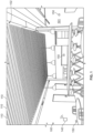
Fig. 1 illustrates a perspective view of an example indoor environment having a dynamic acoustic system in a first configuration in accordance with various embodiments of the present disclosure; -
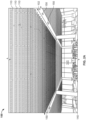
Fig. 2A illustrates a perspective view of an example indoor environment having a dynamic acoustic system in a first configuration in accordance with various embodiments of the present disclosure; -
Fig. 2B illustrates a perspective view of the example indoor environment ofFig. 2A having the dynamic acoustic system in a second configuration in accordance with various embodiments of the present disclosure; -
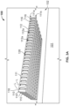
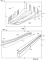
Fig. 3A illustrates a perspective view of a first example dynamic acoustic accessory of the example dynamic acoustic system ofFigs. 1-2B in a closed configuration in accordance with various embodiments of the present disclosure; -
Fig. 3B illustrates a perspective view of the example dynamic acoustic accessory of the example dynamic acoustic system ofFigs. 1-3A in an open configuration in accordance with various embodiments of the present disclosure; -
Fig. 4 illustrates a perspective view of a second alternative example dynamic acoustic accessory in an open configuration in accordance with various embodiments of the present disclosure; -
Fig. 5 illustrates a perspective view of a third alternative example dynamic acoustic accessory in an open configuration in accordance with various embodiments of the present disclosure; -
Fig. 6A illustrates a perspective view of a fourth alternative example dynamic acoustic accessory in a closed configuration in accordance with various embodiments of the present disclosure; -
Fig. 6B illustrates a perspective view of the fourth alternative example dynamic acoustic accessory ofFig. 6A in a partially opened configuration in accordance with various embodiments of the present disclosure; -
Fig. 6C illustrates a perspective view of the fourth alternative example dynamic acoustic accessory ofFigs. 6A and6B in an open configuration in accordance with various embodiments of the present disclosure; -
Fig. 7 illustrates an upper perspective view of the fourth alternative example dynamic acoustic accessory ofFigs. 6A-6C in accordance with various embodiments of the present disclosure; -
Fig. 8 illustrates a cross-sectional view of the fourth alternative example dynamic acoustic accessory ofFigs. 6A-7 in accordance with various embodiments of the present disclosure; -
Fig. 9 illustrates a perspective view of a fifth alternative example dynamic acoustic accessory in accordance with various embodiments of the present disclosure; -
Fig. 10 illustrates a perspective view of a sixth alternative example dynamic acoustic accessory in accordance with various embodiments of the present disclosure; and -
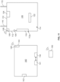
Fig. 11 illustrates a schematic of the dynamic acoustic system in accordance with various embodiments of the present disclosure. - Skilled artisans will appreciate that elements in the figures are illustrated for simplicity and clarity and have not necessarily been drawn to scale. For example, the dimensions and/or relative positioning of some of the elements in the figures may be exaggerated relative to other elements to help to improve understanding of various embodiments of the present invention. Also, common but well-understood elements that are useful or necessary in a commercially feasible embodiment are often not depicted in order to facilitate a less obstructed view of these various embodiments. It will further be appreciated that certain actions and/or steps may be described or depicted in a particular order of occurrence while those skilled in the art will understand that such specificity with respect to sequence is not actually required. It will also be understood that the terms and expressions used herein have the ordinary technical meaning as is accorded to such terms and expressions by persons skilled in the technical field as set forth above except where different specific meanings have otherwise been set forth herein.
- Generally speaking, a dynamic acoustic ceiling system includes panelized ceiling elements equipped with components that can alter intrinsic acoustic characteristics of the indoor environment. Each panel includes active, operable, mechanical elements to conceal or expose, to varying degrees, an interior region that, in some examples, includes sound-absorbing materials. Such sound-absorbing materials may be passive or active sound absorbers. Each panel may additionally include embedded transducers (e.g., loudspeakers) to provide active, adjustable sound masking or voice reinforcement. All active and adjustable elements of each panel may be controlled by a programmable digital sound processor ("DSP") that receives an input by one or more integrated sensors (e.g., microphones). When multiple panels are combined as a system, they may communicate with each other via a unified digital control system to create a programmable, self-adjusting acoustic environment.
- Referring now to the drawings, a dynamic
acoustic system 100 is provided for use in connection with anindoor environment 101 having aceiling member 102. Thesystem 100 includes any number of elongatedacoustic bars 110, acontroller 140 operably coupled to each of theacoustic bars 110, and at least onesensor 150 operably coupled to thecontroller 140. Theacoustic bars 110 can be provided in a number of forms that include any or all of the following subcomponents. Theacoustic bars 110 are in the form of ashell 111 having anupper portion 111a, alower portion 111b, and a number of side surfaces 112 extending therebetween. The side surfaces 112 have any number ofopenings 112a. As illustrated inFigs. 1-8 , theacoustic bars 110 have a generally rectangular prismatic shape, though other shapes and configurations are possible. Theshell 111 of theacoustic bars 110 define a generally hollow interior region 114 (Fig. 3B ) therein. Accordingly, theopenings 112a formed on the side surfaces 112 create a sound pathway between theenvironment 101 and theinterior region 114 of theshell 111. - The
acoustic bars 110 may be mounted to theceiling member 102 via any number of suitable mountingstructures 115. For example, theacoustic bars 110 may be directly adhered to theceiling 102 via adhesives, fasteners such as bolts and/or brackets, and the like. Other examples of suitable mounting approaches will be discussed in further detail below. - Each of the
acoustic bars 110 includes at least one movable element that selectively creates a pathway for sound waves to enter into theinterior region 114 from theenvironment 101. As illustrated inFigs. 2A-3B , the movable element is in the form of amovable louvre 116 or baffle positioned along any number of side surfaces 112 of theshell 111. Themovable louvre 116 is in the form of a generally flat panel having a rectangular shape extending along a longitudinal axis "L", though any desired shape or configuration may be used. - In some examples, the
movable louvre 116 is rotatably coupled to theshell 111 via apin 118 or other hinged mounting member. Themovable louvre 116 may define a mounting orifice (not illustrated) through which thepin 118 is inserted to secure themovable louvre 116 to theshell 111. In some approaches, the mounting mechanism may include a spring or other resilient member that maintains themovable louvre 116 in a normally-closed position. Adrive mechanism 120 may be coupled to eachmovable louvre 116 that causes themovable louvre 116 to move. In some examples, thesystem 100 may use onedrive mechanism 120 for eachmovable louvre 116 to allow for fine-turning a number of open sound pathways. In other examples, however, onedrive mechanism 120 may be operably coupled to a number ofmovable louvres 116 to control their operation. In yet other examples, any number ofdrive mechanisms 120 may be used to drive any desired number ofmovable louvres 116. Further, in some examples, thedrive mechanism 120 may be releasably coupled to eachmovable louvre 116 such that thedrive mechanism 120 may selectively exert a driving force on a desiredmovable louvre 116 when desired. One such example of a releasable coupling system is a cam system; though other examples are possible. - The
drive mechanism 120 may be in the form of a motor, a servo-motor, a solenoid or other actuator, a geared mechanism, a pulley mechanism, and the like. Other examples are possible. Thedrive mechanism 120 may be uni-directional - meaning it exerts an urging force on the movable louvre 116 a single direction, or alternatively may be multi-directional - meaning it exerts an urging force on themovable louvre 116 in multiple directions. - As illustrated in
Fig. 3B , in some examples, thepin 118 is positioned along the longitudinal axis L of themovable louvre 116 such that themovable louvre 116 is rotatable about the longitudinal axis L. In these examples, the movable louvre is rotatable between a first fully closed position (Fig. 3A ) and a second fully open position (Fig. 3B ). Themovable louvre 116 may be positioned at any intermediate position between the closed and opened positions as desired to selectively alter a size of the opening into theinterior region 114 of theshell 111. In other words, any number ofmovable louvres 116 may be selectively rotated to provide for varying openings which create the sound pathways between theenvironment 101 and theinterior region 114 of theshell 111. - In some examples, the
acoustic bars 110 may also include a sound-absorbingmaterial 122 at least partially disposed within theinterior region 114. When theinterior region 114 of theacoustic bars 110 is exposed to theenvironment 101 and air-borne sound waves, based on the positioning of themovable louvres 116, the sound-absorbingmaterial 122 will absorb the sound waves to reduce an overall decibel level of theenvironment 101. In some examples, the sound-absorbingmaterial 122 are passive absorbers such as glass fibers and/or mineral fibers. In other examples, the sound-absorbingmaterial 122 are active, adjustable absorbers such as acoustic metamaterials. Any combination of passive and/or active materials may be used. - In some examples, the
acoustic bars 110 may additionally include at least one sound-generatingdevice 124 coupled and/or disposed adjacent thereto. Specifically, in some examples, the sound-generatingdevice 124 may be disposed at theupper portion 111a of the shell and may be pointed downwardly such that sound waves generated by the sound generating-device 124 are directed into theinterior region 114 of theshell 111. The sound-generatingdevice 124 may be an electroacoustic transducer that generates sound to provide adjustable sound masking and/or sound reinforcement, depending on the desired application. In some examples, the sound-generatingdevice 124 is a loudspeaker, a cluster of loudspeakers, distributed mode loudspeakers, and/or focused loudspeaker arrays. Any number or combination of these sound-generatingdevices 124 may be positioned and/or disposed within theacoustic bars 110. - The
acoustic bars 110 may further include a programmable controller such as a digital signal processor (DSP) 126 that controls the active acoustic elements (e.g., themovable louvres 116, the sound-absorbingmaterial 122, and/or the sound-generatingdevice 124. TheDSP 126 may include acommunication link 128 that communicates with thecontroller 140 in a manner described below. - Specifically, turning to
Fig. 11 , as previously noted, the dynamicacoustic system 100 includes aprimary controller 140 that is communicatively coupled with each of theacoustic bars 110 viaconnection 145 that communicates with thecommunication link 128 of theDSP 126. In some examples, thecontroller 140 may not be communicatively coupled to each of theacoustic bars 110, rather, any number ofacoustic bars 110 may be daisy-chained to each other such that oneacoustic bar 110 may control the operation of several additionalacoustic bars 110. Theconnection 145 may be any type of wired and/or wireless communications protocol adapted to transmit and/or receive electronic signals. In these examples, thecontroller 140 is in signal communication with at least one sensor, such as, for example,sensor 150 located in theenvironment 101 at any desired location. Any number of additional sensors capable of sensing any number of characteristics of theenvironment 101 and/or theacoustic bars 110 may be used and placed at desired locations. - The
controller 140 can be disposed in a number of positions with respect to theenvironment 101. As examples, thecontroller 140 can be placed on a wall or in a discrete location. In some examples, thecontroller 140 may be integral with one of theacoustic bars 110, for example, thecontroller 140 may be contained in an enclosure that is mounted on one of theacoustic bars 110, contained in a separate enclosure that is positioned adjacent or proximate to one of theacoustic bars 110, or can be positioned remotely. In some embodiments, thecontroller 140 can partially or fully control functions of theacoustic bars 110 via wired and/or wired signal communications as known and/or commonly used in the art. - The
sensor 150 may be any type of sensor adapted to measure (either directly or indirectly) one or more characteristics of theenvironment 101 and/or theacoustic bars 110. Thesensor 150 may measure any environmental characteristic, such as, for example, a decibel level, a vibration level, a number of people in the environment, illumination levels, motion (e.g., via a Pyroelectric ("Passive") InfraRed Sensors), temperatures, humidity, air flow, air particulates, gases such as carbon monoxide, air pressure, and/or electromagnetic disturbances, or any one or more of any number of additional characteristics which are indicative of these. Further still, sound (sonar) waves, radio waves, light waves (LIDAR), and computer vision may also be used to map and/or identify physical objects and/or people within theenvironment 101. - As an example, the
sensor 150 may be a microphone or array of microphones, though other examples are possible. When microphones are implemented, systems may be used to identify individual people using voice-recognition algorithms that identify unique voices. Such a system can be used in conjunction with speakers to generate a level sound volume throughout theenvironment 101 and/or to enhance the sound of human speech. Further, such a system may act as an intercom system, may be capable of responding to voice commands, and/or detect equipment failures. - The
sensor 150 generates a signal which is transmitted to an input of thecontroller 140. In some examples, thecontroller 140 can be set, configured, and/or programmed with logic, commands, and/or executable program instructions to provide appropriate correction factors to estimate or calculate values for the measured characteristic in theenvironment 101. - In some embodiments, the
controller 140 generates a signal which is transmitted from an output of thecontroller 140 to theDSP 126. Thecontroller 140 can control any number of characteristics of theacoustic bars 110, such as, for example, activation of any combination ofdrive mechanisms 120, any active sound-absorbingmaterials 122, and/or any combination of sound-generatingdevices 124. - The signal or signals from the
controller 140 may be used to control operation of thesystem 100 such that variations in environmental characteristics influencing decibel levels are taken into account by thecontroller 140. Adjustments may be made by thecontroller 140 in real time or in near-real time (that is, with a minimal delay betweensensors 150 sensing values and changes being made to the system 100), or corrections can be made with some delay. Furthermore, historical data may be used as a basis for making adjustments to thesystem 100. Thecontroller 140 may be connected to thesensors 150 and theDSP 126 and/or any other components in thesystem 100 via any type of signal communication approach known in the art. - The
controller 140 may also be a DSP that includessoftware 141 adapted to control its operation, any number of hardware elements 142 (such as, for example, a non-transitory memory module and/or processors), any number ofinputs 143, any number ofoutputs 144, and any number ofconnections 145. Thesoftware 141 may be loaded directly onto a non-transitory memory module of thecontroller 140 in the form of a non-transitory computer readable medium, or may alternatively be located remotely from thecontroller 140 and be in communication with thecontroller 140 via any number of controlling approaches. Thesoftware 141 includes logic, commands, and/or executable program instructions which may contain logic and/or commands for controlling theacoustic bars 110 according to a desired operational program. Thesoftware 141 may or may not include an operating system, an operating environment, an application environment, and/or a user interface. - The
hardware 142 uses theinputs 143 to receive signals, data, and information from the components being controlled by thecontroller 140. Thehardware 142 uses theoutputs 144 to send signals, data, and/or other information to theacoustic bars 110. Theconnection 145 represents a pathway through which signals, data, and information can be transmitted between thecontroller 140 and theacoustic bars 110. In various embodiments this pathway may be a physical connection or a non-physical communication link that works analogous to a physical connection, direct or indirect, configured in any way described herein or known in the art. In various embodiments, thecontroller 140 can be configured in any additional or alternate way known in the art. - The
connection 145 represents a pathway through which signals, data, and information can be transmitted between thecontroller 140 and theinjection molding machine 100. In various embodiments, these pathways may be physical connections or non-physical communication links that work analogously to either direct or indirect physical connections configured in any way described herein or known in the art. In various embodiments, thecontroller 140 can be configured in any additional or alternate way known in the art. - In operation, the
sensor 150 measures the environmental characteristic (e.g., airborne sound in the vicinity of the system 100). Based on user settings of thecontroller 140 and the incoming signals from thesensors 150, thecontroller 140 transmits signals to theoutputs 144 that enables the adjustment of a particular number ofacoustic bars 110 to enable theacoustic bars 110 to change its acoustic properties. Thesystem 100 allows for high levels of granularity - for example, thecontroller 140 may only need to move a singlemovable louvre 116 on a singleacoustic bar 110 to adjust the environmental characteristic to a desired level. Conversely, thecontroller 140 may move any number ofmovable louvres 116 on any number ofacoustic bars 110 to adjust the environmental characteristic to a desired level. When multipleacoustic bars 110 are used in thesystem 100, they may communicate with each other via a unified digital control system to create a programmable, self-adjusting dynamic acoustic environment. - In some examples, a routine may be implemented on the
controller 140 that may or may not rely on sensed measurements. For example, the program may be time-based such that the active control elements of theacoustic bars 110 are activated and/or actuated at specific times (e.g., during busy periods within the environment 101). - Turning to
Fig. 4 , asystem 200 having an alternativeacoustic bar 210 design is provided that includes similar features as theacoustic bar 110 described inFigs. 3A and3B , and thus will not be described in substantial detail. However, in this illustrated example, themovable louvres 216 are rotatably mounted to thesidewalls 212 in a transverse direction relative to the longitudinal axis L. As a result, themovable louvres 216 rotate outwardly from the shell 211, which may provide for more increased reflection of sound waves (compared to the example configuration illustrated inFig. 3B where sound waves are less restricted from entering theinterior region 114 of theshell 111 when themovable louvres 116 are in the open position). As before, any number ofmovable louvres 216 may be coupled to any number ofdrive mechanisms 220 to allow for individual control of themovable louvres 216 if desired. - Turning to
Fig. 5 , a system 300 having an alternativeacoustic bar 310 design is provided that includes similar features as theacoustic bars Figs. 3A-4 , and thus will not be described in substantial detail. However, in this illustrated example, themovable louvres 316 are slidably mounted to thesidewalls 312. In other words, in these examples, themovable louvres 316 may slide relative to theopenings 312a formed on thesidewalls 312 via any number of arrangements such as tracks, channels, and the like. As before, any number ofmovable louvres 316 may be coupled to any number ofdrive mechanisms 320 to allow for individual control of themovable louvres 316 if desired. Themovable louvres 316 may be single or multi-layered as desired. - Turning to
Figs. 6A-8 , asystem 400 having an alternativeacoustic bar 410 design is provided that includes similar features as theacoustic bars Figs. 3A-5 , and thus will not be described in substantial detail. However, in this illustrated example, the movable element is in the form of amovable base member 416 operably coupled to theshell 411. In these examples, themovable base member 416 lowers from thelower portion 411b of theshell 411 to expose the interior region 414 (which may accommodate sound-absorbingmaterial 422 and/or a sound generating device 424) thereof. - More specifically, the
acoustic bar 410 is coupled to theceiling member 402 via a mountingstructure 415, which, in these examples may be a chain or rod member. Themovable base member 416 is in the form of anelongated platform 417 extending all or a portion of the length of theacoustic bar 410. As illustrated inFigs. 6C and7 , themovable base member 416 is secured to theshell 411 and/or the mountingstructure 415 via abase support 418 that is driven by adrive mechanism 420. In some examples, thebase support 418 may be in the form of a pulley system, a piston or other telescoping mechanism, and/or any other mechanism that generates axial movement. Thedrive mechanism 420 may be a solenoid actuator, a motor, a resilient member (e.g., a torsion spring, an axial spring, a watch spring, etc.) capable of urging thebase support 418 downwardly. In examples where the mountingstructure 415 is a rod member, a portion of therod member 415 may form thebase support 418 and/or thedrive mechanism 420 that lowers themovable base member 416. - As illustrated in
Fig. 6B , upon receiving an input from thecontroller 140, theDSP 426 activates thedrive mechanism 420 to extend themovable base member 416 to a desired level relative to thelower portion 411b of theshell 411, thus exposing theinterior region 414 of theshell 411. The extension of themovable base member 416 can be adjusted based on the desired environmental characteristic. As before, thecontroller 140 may further cause theDSP 426 to activate the sound absorbing material 422 (if so equipped) and/or the sound-generating device 424 (if so equipped). - Turning to
Fig. 9 , asystem 500 having an alternativeacoustic bar 510 design is provided that includes similar features as theacoustic bar 410 described inFigs. 6A-8 , and thus will not be described in substantial detail. However, in this illustrated example, theacoustic bar 510 is in the form of anelongated shell 511 having a wave-like or curved pattern. - Turning to
Fig. 10 , asystem 600 having an alternativeacoustic bar 610 design is provided that includes similar features as theacoustic bars Figs. 6A-9 , and thus will not be described in substantial detail. However, in this illustrated example, the components of theacoustic bar 610 are generally reversed in that theshell 611 is movable downwardly relative to anupper base member 616, which is mounted to the ceiling via any number of approaches. - In some examples, any desired combination of movable elements (e.g., movable louvres and movable base members) may be used that move relative to the shell in any of the described approaches. In other words, any number of
movable louvres 116 may be rotatably coupled to thesidewalls 112 along the longitudinal axis L, any number ofmovable louvres 216 may be rotatably coupled to the sidewalls2112 transversely to the longitudinal axis L, any number ofmovable louvres 316 may be slidably coupled to thesidewalls 312, and any number ofmovable base members 416 may be coupled to theshell 411 to extend therefrom as desired. - So configured, the system provides enhanced sound altering characteristics while covering a limited amount of ceiling surface. Such a system is tunable as desired to allow for an adjustable amount of reverb in certain situations (e.g., when the environment is less populated) and more absorptive in other situations (e.g., when the environment is more populated). Further, by incorporating speakers into each of the panels, additional speakers are no longer needed, thus reducing assembly steps and complexity of the panels.
- Those skilled in the art will recognize that a wide variety of modifications, alterations, and combinations can be made with respect to the above described embodiments without departing from the scope of the invention as defined in the appended claims.
Claims (10)
- A dynamic acoustic system (100) for use in connection with an indoor environment (101), the dynamic acoustic system comprising:
a plurality of elongated acoustic bars (110) each being operably coupled to and positioned below a ceiling member (102) of the indoor environment, each of the plurality of acoustic bars including:an upper portion (111a),a lower portion (111b),a plurality of side surfaces (112) extending between the upper portion and the lower portion,an interior region (114) at least partially defined by the upper portion, the lower portion, and the plurality of side surfaces, andat least one movable element (116) positioned on at least one of the plurality of side surfaces, the at least one movable element being movable between a first position and a second position;a controller (140) operably coupled to each of the plurality of elongated acoustic bar to selectively control operation of the at least one movable element of a desired number of the plurality of elongated acoustic bars to alter an acoustic characteristic of the indoor environment. - The dynamic acoustic system of claim 1, further comprising a sensor (150) coupled to controller, the sensor adapted to measure an acoustic characteristic of the indoor environment.
- The dynamic acoustic system of claim 2, wherein the sensor comprises at least one of a microphone or a vibration sensor.
- The dynamic acoustic system of any one of claims 1-3, further comprising a sound absorbing material (122) at least partially disposed within the interior region of the plurality of elongated acoustic bars.
- The dynamic acoustic system of any one of claims 1-4, further comprising at least one sound generating device (124) positioned at or near the plurality of elongated acoustic bars and being operably coupled to the controller, wherein the controller further selectively controls operation of the at least one sound generating device.
- The dynamic acoustic system of any one of claims 1-5, wherein the at least one movable element comprises a plurality of louvres (116), wherein the controller is adapted to transmit a signal that selectively causes a number of the plurality of louvres to move.
- The dynamic acoustic system of claim 6, wherein the plurality of louvres are disposed on at least one of the plurality of side surfaces of the elongated acoustic bar.
- The dynamic acoustic accessory of claim 6 or 7, wherein at least one of the plurality of movable louvres is individually actuable via a drive mechanism coupled thereto, the drive mechanism configured to selectively rotate the at least one movable louvre relative to the elongated shell.
- The dynamic acoustic system of any one of claims 1-5, wherein the at least one movable element comprises a movable base member adapted to lower from the lower portion.
- The dynamic acoustic accessory of claim 9, wherein the movable base member comprises an elongated platform and a drive mechanism coupled to the elongated platform, the drive mechanism configured to selectively move the elongated platform away from the lower portion of the elongated shell.
Applications Claiming Priority (3)
| Application Number | Priority Date | Filing Date | Title |
|---|---|---|---|
| US201962852672P | 2019-05-24 | 2019-05-24 | |
| US16/788,607 US11674306B2 (en) | 2019-05-24 | 2020-02-12 | Smart dynamic acoustic ceiling panel |
| PCT/US2020/033514 WO2020242815A1 (en) | 2019-05-24 | 2020-05-19 | Dynamic acoustic ceiling system |
Publications (3)
| Publication Number | Publication Date |
|---|---|
| EP3976896A1 EP3976896A1 (en) | 2022-04-06 |
| EP3976896C0 EP3976896C0 (en) | 2025-03-12 |
| EP3976896B1 true EP3976896B1 (en) | 2025-03-12 |
Family
ID=73457470
Family Applications (1)
| Application Number | Title | Priority Date | Filing Date |
|---|---|---|---|
| EP20735043.0A Active EP3976896B1 (en) | 2019-05-24 | 2020-05-19 | Dynamic acoustic ceiling system |
Country Status (8)
| Country | Link |
|---|---|
| US (1) | US11674306B2 (en) |
| EP (1) | EP3976896B1 (en) |
| JP (1) | JP7475372B2 (en) |
| CA (1) | CA3140136A1 (en) |
| ES (1) | ES3018138T3 (en) |
| MX (1) | MX2021013198A (en) |
| PL (1) | PL3976896T3 (en) |
| WO (1) | WO2020242815A1 (en) |
Families Citing this family (1)
| Publication number | Priority date | Publication date | Assignee | Title |
|---|---|---|---|---|
| US11505941B2 (en) * | 2021-03-02 | 2022-11-22 | Lumicor Inc. | Ceiling tile system |
Family Cites Families (20)
| Publication number | Priority date | Publication date | Assignee | Title |
|---|---|---|---|---|
| US2698071A (en) * | 1949-11-14 | 1954-12-28 | Cepco Inc | Light control fixture |
| US3411605A (en) | 1967-03-27 | 1968-11-19 | Moody L. Coffman | Acoustic conrol units |
| US3590354A (en) * | 1969-05-01 | 1971-06-29 | Foey M Shiflet | Control system for synchronously controlling the opposed rotation of elements about coincident or parallel axes |
| JP2877874B2 (en) * | 1990-02-16 | 1999-04-05 | 大成建設株式会社 | Reverberation control device |
| US9294839B2 (en) * | 2013-03-01 | 2016-03-22 | Clearone, Inc. | Augmentation of a beamforming microphone array with non-beamforming microphones |
| US9322165B2 (en) | 2014-07-25 | 2016-04-26 | Erik J. Luhtala | Dynamically adjustable acoustic panel device, system and method |
| US9499977B2 (en) * | 2014-11-10 | 2016-11-22 | Wenger Corporation | Motorized acoustical banner |
| CA2931869C (en) * | 2015-06-03 | 2023-10-17 | Epic Metals Corporation | Tunable specular acoustic deck |
| US10760265B2 (en) * | 2016-07-11 | 2020-09-01 | JayVic, LLC | Folding variable acoustic assembly and method of use |
| US10119269B2 (en) * | 2016-07-11 | 2018-11-06 | Jayvic, Inc. | Variable acoustic assembly and method of use |
| USD840551S1 (en) * | 2016-09-09 | 2019-02-12 | Arktura Llc | Architectural fixture |
| US10961700B2 (en) * | 2017-02-27 | 2021-03-30 | Knoll, Inc. | Noise reduction apparatus and method of making and using the same |
| DK179483B1 (en) * | 2017-03-05 | 2018-12-17 | Werner Adelmann-Larsen Niels | Variable Acoustic Technology for Rooms |
| US11211040B2 (en) * | 2017-09-15 | 2021-12-28 | Focal Point, Llc | Modular fixture with integrated acoustic sound absorbing housing |
| US11566419B2 (en) * | 2018-06-12 | 2023-01-31 | Durali System Design & Automation Co. | Controlling acoustics of a performance space |
| AU2018102128A4 (en) * | 2018-10-22 | 2019-05-02 | Instyle Contract Textiles Pty Ltd | Ceiling module |
| US10359163B1 (en) * | 2018-10-30 | 2019-07-23 | Usg Interiors, Llc | Accessible ceiling baffles with integrated lighting, custom perforation, and acoustics |
| US10672376B1 (en) * | 2019-04-01 | 2020-06-02 | Eaton Intelligent Power Limited | Acoustic luminaires |
| US11142914B1 (en) * | 2019-08-26 | 2021-10-12 | Valmont Industries, Inc. | System, method and apparatus for providing a sound absorbing composite wall |
| DE202020101867U1 (en) * | 2020-04-06 | 2021-07-13 | Pinta Acoustic Gmbh | Sound absorber |
-
2020
- 2020-02-12 US US16/788,607 patent/US11674306B2/en active Active
- 2020-05-19 PL PL20735043.0T patent/PL3976896T3/en unknown
- 2020-05-19 EP EP20735043.0A patent/EP3976896B1/en active Active
- 2020-05-19 MX MX2021013198A patent/MX2021013198A/en unknown
- 2020-05-19 CA CA3140136A patent/CA3140136A1/en active Pending
- 2020-05-19 ES ES20735043T patent/ES3018138T3/en active Active
- 2020-05-19 WO PCT/US2020/033514 patent/WO2020242815A1/en not_active Ceased
- 2020-05-19 JP JP2021569457A patent/JP7475372B2/en active Active
Also Published As
| Publication number | Publication date |
|---|---|
| US20200370292A1 (en) | 2020-11-26 |
| PL3976896T3 (en) | 2025-04-22 |
| CA3140136A1 (en) | 2020-12-03 |
| US11674306B2 (en) | 2023-06-13 |
| JP2022534697A (en) | 2022-08-03 |
| MX2021013198A (en) | 2021-12-10 |
| EP3976896C0 (en) | 2025-03-12 |
| WO2020242815A1 (en) | 2020-12-03 |
| ES3018138T3 (en) | 2025-05-14 |
| EP3976896A1 (en) | 2022-04-06 |
| JP7475372B2 (en) | 2024-04-26 |
Similar Documents
| Publication | Publication Date | Title |
|---|---|---|
| KR102141403B1 (en) | Dynamically responsive acoustic tuning envelope system and method | |
| US11566419B2 (en) | Controlling acoustics of a performance space | |
| EP2212158B1 (en) | Vehicle audio system including door-mounted components | |
| US11692345B2 (en) | Modular dynamic acoustic ceiling panel | |
| US20060285697A1 (en) | Open-air noise cancellation for diffraction control applications | |
| US8620003B2 (en) | Embedded audio system in distributed acoustic sources | |
| US11674306B2 (en) | Smart dynamic acoustic ceiling panel | |
| JP2017511904A (en) | Intelligent acoustic control system | |
| KR101765993B1 (en) | Variable Reverberator with Frequency Selection and Diffusor | |
| JP5602039B2 (en) | Sound masking system | |
| US20110211721A1 (en) | Adaptive noise generating device | |
| GB2565033A (en) | Acoustic resonators | |
| JP2006138149A (en) | Partition member with acoustic function | |
| JPH03239296A (en) | Reverberation time controller | |
| JP2022150888A (en) | Speaker and interior structure | |
| KR100922963B1 (en) | User speech recognition apparatus using microphone array and method for driving microphone array | |
| KR101143782B1 (en) | Microphone and the control apparatus and the method thereof | |
| US12464277B2 (en) | Air flow control valve structure for audio device | |
| KR20230094515A (en) | System with adjustable angle for varying the reverberation time | |
| JP2022150925A (en) | Indoor structure having acoustic system | |
| JP2004198584A (en) | Sound field variable system | |
| SE0403186L (en) | Baffelljuddämpare | |
| SE1630240A2 (en) | Sound valve |
Legal Events
| Date | Code | Title | Description |
|---|---|---|---|
| STAA | Information on the status of an ep patent application or granted ep patent |
Free format text: STATUS: UNKNOWN |
|
| STAA | Information on the status of an ep patent application or granted ep patent |
Free format text: STATUS: THE INTERNATIONAL PUBLICATION HAS BEEN MADE |
|
| PUAI | Public reference made under article 153(3) epc to a published international application that has entered the european phase |
Free format text: ORIGINAL CODE: 0009012 |
|
| STAA | Information on the status of an ep patent application or granted ep patent |
Free format text: STATUS: REQUEST FOR EXAMINATION WAS MADE |
|
| 17P | Request for examination filed |
Effective date: 20211213 |
|
| AK | Designated contracting states |
Kind code of ref document: A1 Designated state(s): AL AT BE BG CH CY CZ DE DK EE ES FI FR GB GR HR HU IE IS IT LI LT LU LV MC MK MT NL NO PL PT RO RS SE SI SK SM TR |
|
| DAV | Request for validation of the european patent (deleted) | ||
| DAX | Request for extension of the european patent (deleted) | ||
| P01 | Opt-out of the competence of the unified patent court (upc) registered |
Effective date: 20230602 |
|
| GRAP | Despatch of communication of intention to grant a patent |
Free format text: ORIGINAL CODE: EPIDOSNIGR1 |
|
| STAA | Information on the status of an ep patent application or granted ep patent |
Free format text: STATUS: GRANT OF PATENT IS INTENDED |
|
| INTG | Intention to grant announced |
Effective date: 20241016 |
|
| GRAS | Grant fee paid |
Free format text: ORIGINAL CODE: EPIDOSNIGR3 |
|
| GRAA | (expected) grant |
Free format text: ORIGINAL CODE: 0009210 |
|
| STAA | Information on the status of an ep patent application or granted ep patent |
Free format text: STATUS: THE PATENT HAS BEEN GRANTED |
|
| AK | Designated contracting states |
Kind code of ref document: B1 Designated state(s): AL AT BE BG CH CY CZ DE DK EE ES FI FR GB GR HR HU IE IS IT LI LT LU LV MC MK MT NL NO PL PT RO RS SE SI SK SM TR |
|
| REG | Reference to a national code |
Ref country code: GB Ref legal event code: FG4D |
|
| REG | Reference to a national code |
Ref country code: CH Ref legal event code: EP |
|
| REG | Reference to a national code |
Ref country code: DE Ref legal event code: R096 Ref document number: 602020047584 Country of ref document: DE |
|
| REG | Reference to a national code |
Ref country code: IE Ref legal event code: FG4D |
|
| U01 | Request for unitary effect filed |
Effective date: 20250327 |
|
| P04 | Withdrawal of opt-out of the competence of the unified patent court (upc) registered |
Free format text: CASE NUMBER: APP_15706/2025 Effective date: 20250401 |
|
| U07 | Unitary effect registered |
Designated state(s): AT BE BG DE DK EE FI FR IT LT LU LV MT NL PT RO SE SI Effective date: 20250403 |
|
| REG | Reference to a national code |
Ref country code: GR Ref legal event code: EP Ref document number: 20250400609 Country of ref document: GR Effective date: 20250514 |
|
| U20 | Renewal fee for the european patent with unitary effect paid |
Year of fee payment: 6 Effective date: 20250527 |
|
| PG25 | Lapsed in a contracting state [announced via postgrant information from national office to epo] |
Ref country code: RS Free format text: LAPSE BECAUSE OF FAILURE TO SUBMIT A TRANSLATION OF THE DESCRIPTION OR TO PAY THE FEE WITHIN THE PRESCRIBED TIME-LIMIT Effective date: 20250612 |
|
| PGFP | Annual fee paid to national office [announced via postgrant information from national office to epo] |
Ref country code: PL Payment date: 20250503 Year of fee payment: 6 |
|
| PGFP | Annual fee paid to national office [announced via postgrant information from national office to epo] |
Ref country code: GB Payment date: 20250527 Year of fee payment: 6 Ref country code: ES Payment date: 20250602 Year of fee payment: 6 |
|
| PG25 | Lapsed in a contracting state [announced via postgrant information from national office to epo] |
Ref country code: NO Free format text: LAPSE BECAUSE OF FAILURE TO SUBMIT A TRANSLATION OF THE DESCRIPTION OR TO PAY THE FEE WITHIN THE PRESCRIBED TIME-LIMIT Effective date: 20250612 |
|
| PG25 | Lapsed in a contracting state [announced via postgrant information from national office to epo] |
Ref country code: HR Free format text: LAPSE BECAUSE OF FAILURE TO SUBMIT A TRANSLATION OF THE DESCRIPTION OR TO PAY THE FEE WITHIN THE PRESCRIBED TIME-LIMIT Effective date: 20250312 |
|
| PGFP | Annual fee paid to national office [announced via postgrant information from national office to epo] |
Ref country code: GR Payment date: 20250528 Year of fee payment: 6 |
|
| PGFP | Annual fee paid to national office [announced via postgrant information from national office to epo] |
Ref country code: TR Payment date: 20250515 Year of fee payment: 6 |
|
| PG25 | Lapsed in a contracting state [announced via postgrant information from national office to epo] |
Ref country code: SM Free format text: LAPSE BECAUSE OF FAILURE TO SUBMIT A TRANSLATION OF THE DESCRIPTION OR TO PAY THE FEE WITHIN THE PRESCRIBED TIME-LIMIT Effective date: 20250312 |
|
| PG25 | Lapsed in a contracting state [announced via postgrant information from national office to epo] |
Ref country code: CZ Free format text: LAPSE BECAUSE OF FAILURE TO SUBMIT A TRANSLATION OF THE DESCRIPTION OR TO PAY THE FEE WITHIN THE PRESCRIBED TIME-LIMIT Effective date: 20250312 |
|
| PG25 | Lapsed in a contracting state [announced via postgrant information from national office to epo] |
Ref country code: SK Free format text: LAPSE BECAUSE OF FAILURE TO SUBMIT A TRANSLATION OF THE DESCRIPTION OR TO PAY THE FEE WITHIN THE PRESCRIBED TIME-LIMIT Effective date: 20250312 |
|
| PG25 | Lapsed in a contracting state [announced via postgrant information from national office to epo] |
Ref country code: IS Free format text: LAPSE BECAUSE OF FAILURE TO SUBMIT A TRANSLATION OF THE DESCRIPTION OR TO PAY THE FEE WITHIN THE PRESCRIBED TIME-LIMIT Effective date: 20250712 |
|
| REG | Reference to a national code |
Ref country code: CH Ref legal event code: H13 Free format text: ST27 STATUS EVENT CODE: U-0-0-H10-H13 (AS PROVIDED BY THE NATIONAL OFFICE) Effective date: 20251223 |
|
| PLBE | No opposition filed within time limit |
Free format text: ORIGINAL CODE: 0009261 |
|
| STAA | Information on the status of an ep patent application or granted ep patent |
Free format text: STATUS: NO OPPOSITION FILED WITHIN TIME LIMIT |
|
| PG25 | Lapsed in a contracting state [announced via postgrant information from national office to epo] |
Ref country code: CH Free format text: LAPSE BECAUSE OF NON-PAYMENT OF DUE FEES Effective date: 20250531 |
|
| REG | Reference to a national code |
Ref country code: CH Ref legal event code: L10 Free format text: ST27 STATUS EVENT CODE: U-0-0-L10-L00 (AS PROVIDED BY THE NATIONAL OFFICE) Effective date: 20260121 |
|
| PG25 | Lapsed in a contracting state [announced via postgrant information from national office to epo] |
Ref country code: MC Free format text: LAPSE BECAUSE OF FAILURE TO SUBMIT A TRANSLATION OF THE DESCRIPTION OR TO PAY THE FEE WITHIN THE PRESCRIBED TIME-LIMIT Effective date: 20250312 |
|
| 26N | No opposition filed |
Effective date: 20251215 |
|
| PG25 | Lapsed in a contracting state [announced via postgrant information from national office to epo] |
Ref country code: IE Free format text: LAPSE BECAUSE OF NON-PAYMENT OF DUE FEES Effective date: 20250519 |