EP3975975B1 - Closed-system drug-transfer devices for solid dosage forms - Google Patents
Closed-system drug-transfer devices for solid dosage forms Download PDFInfo
- Publication number
- EP3975975B1 EP3975975B1 EP20812576.5A EP20812576A EP3975975B1 EP 3975975 B1 EP3975975 B1 EP 3975975B1 EP 20812576 A EP20812576 A EP 20812576A EP 3975975 B1 EP3975975 B1 EP 3975975B1
- Authority
- EP
- European Patent Office
- Prior art keywords
- plunger
- barrel
- closed
- syringe
- grinding
- Prior art date
- Legal status (The legal status is an assumption and is not a legal conclusion. Google has not performed a legal analysis and makes no representation as to the accuracy of the status listed.)
- Active
Links
Images





Classifications
-
- A—HUMAN NECESSITIES
- A61—MEDICAL OR VETERINARY SCIENCE; HYGIENE
- A61J—CONTAINERS SPECIALLY ADAPTED FOR MEDICAL OR PHARMACEUTICAL PURPOSES; DEVICES OR METHODS SPECIALLY ADAPTED FOR BRINGING PHARMACEUTICAL PRODUCTS INTO PARTICULAR PHYSICAL OR ADMINISTERING FORMS; DEVICES FOR ADMINISTERING FOOD OR MEDICINES ORALLY; BABY COMFORTERS; DEVICES FOR RECEIVING SPITTLE
- A61J7/00—Devices for administering medicines orally, e.g. spoons; Pill counting devices; Arrangements for time indication or reminder for taking medicine
- A61J7/0007—Pill breaking or crushing devices
-
- A—HUMAN NECESSITIES
- A61—MEDICAL OR VETERINARY SCIENCE; HYGIENE
- A61J—CONTAINERS SPECIALLY ADAPTED FOR MEDICAL OR PHARMACEUTICAL PURPOSES; DEVICES OR METHODS SPECIALLY ADAPTED FOR BRINGING PHARMACEUTICAL PRODUCTS INTO PARTICULAR PHYSICAL OR ADMINISTERING FORMS; DEVICES FOR ADMINISTERING FOOD OR MEDICINES ORALLY; BABY COMFORTERS; DEVICES FOR RECEIVING SPITTLE
- A61J15/00—Feeding-tubes for therapeutic purposes
- A61J15/0026—Parts, details or accessories for feeding-tubes
-
- A—HUMAN NECESSITIES
- A61—MEDICAL OR VETERINARY SCIENCE; HYGIENE
- A61J—CONTAINERS SPECIALLY ADAPTED FOR MEDICAL OR PHARMACEUTICAL PURPOSES; DEVICES OR METHODS SPECIALLY ADAPTED FOR BRINGING PHARMACEUTICAL PRODUCTS INTO PARTICULAR PHYSICAL OR ADMINISTERING FORMS; DEVICES FOR ADMINISTERING FOOD OR MEDICINES ORALLY; BABY COMFORTERS; DEVICES FOR RECEIVING SPITTLE
- A61J3/00—Devices or methods specially adapted for bringing pharmaceutical products into particular physical or administering forms
- A61J3/002—Compounding apparatus specially for enteral or parenteral nutritive solutions
-
- A—HUMAN NECESSITIES
- A61—MEDICAL OR VETERINARY SCIENCE; HYGIENE
- A61J—CONTAINERS SPECIALLY ADAPTED FOR MEDICAL OR PHARMACEUTICAL PURPOSES; DEVICES OR METHODS SPECIALLY ADAPTED FOR BRINGING PHARMACEUTICAL PRODUCTS INTO PARTICULAR PHYSICAL OR ADMINISTERING FORMS; DEVICES FOR ADMINISTERING FOOD OR MEDICINES ORALLY; BABY COMFORTERS; DEVICES FOR RECEIVING SPITTLE
- A61J7/00—Devices for administering medicines orally, e.g. spoons; Pill counting devices; Arrangements for time indication or reminder for taking medicine
- A61J7/0015—Devices specially adapted for taking medicines
- A61J7/0053—Syringes, pipettes or oral dispensers
-
- A—HUMAN NECESSITIES
- A61—MEDICAL OR VETERINARY SCIENCE; HYGIENE
- A61M—DEVICES FOR INTRODUCING MEDIA INTO, OR ONTO, THE BODY; DEVICES FOR TRANSDUCING BODY MEDIA OR FOR TAKING MEDIA FROM THE BODY; DEVICES FOR PRODUCING OR ENDING SLEEP OR STUPOR
- A61M5/00—Devices for bringing media into the body in a subcutaneous, intra-vascular or intramuscular way; Accessories therefor, e.g. filling or cleaning devices, arm-rests
- A61M5/178—Syringes
- A61M5/1782—Devices aiding filling of syringes in situ
-
- A—HUMAN NECESSITIES
- A61—MEDICAL OR VETERINARY SCIENCE; HYGIENE
- A61M—DEVICES FOR INTRODUCING MEDIA INTO, OR ONTO, THE BODY; DEVICES FOR TRANSDUCING BODY MEDIA OR FOR TAKING MEDIA FROM THE BODY; DEVICES FOR PRODUCING OR ENDING SLEEP OR STUPOR
- A61M5/00—Devices for bringing media into the body in a subcutaneous, intra-vascular or intramuscular way; Accessories therefor, e.g. filling or cleaning devices, arm-rests
- A61M5/178—Syringes
- A61M5/19—Syringes having more than one chamber, e.g. including a manifold coupling two parallelly aligned syringes through separate channels to a common discharge assembly
-
- A—HUMAN NECESSITIES
- A61—MEDICAL OR VETERINARY SCIENCE; HYGIENE
- A61M—DEVICES FOR INTRODUCING MEDIA INTO, OR ONTO, THE BODY; DEVICES FOR TRANSDUCING BODY MEDIA OR FOR TAKING MEDIA FROM THE BODY; DEVICES FOR PRODUCING OR ENDING SLEEP OR STUPOR
- A61M5/00—Devices for bringing media into the body in a subcutaneous, intra-vascular or intramuscular way; Accessories therefor, e.g. filling or cleaning devices, arm-rests
- A61M5/178—Syringes
- A61M5/31—Details
- A61M5/3129—Syringe barrels
- A61M5/3135—Syringe barrels characterised by constructional features of the proximal end
-
- A—HUMAN NECESSITIES
- A61—MEDICAL OR VETERINARY SCIENCE; HYGIENE
- A61M—DEVICES FOR INTRODUCING MEDIA INTO, OR ONTO, THE BODY; DEVICES FOR TRANSDUCING BODY MEDIA OR FOR TAKING MEDIA FROM THE BODY; DEVICES FOR PRODUCING OR ENDING SLEEP OR STUPOR
- A61M5/00—Devices for bringing media into the body in a subcutaneous, intra-vascular or intramuscular way; Accessories therefor, e.g. filling or cleaning devices, arm-rests
- A61M5/178—Syringes
- A61M5/31—Details
- A61M5/315—Pistons; Piston-rods; Guiding, blocking or restricting the movement of the rod or piston; Appliances on the rod for facilitating dosing ; Dosing mechanisms
- A61M5/31511—Piston or piston-rod constructions, e.g. connection of piston with piston-rod
- A61M5/31513—Piston constructions to improve sealing or sliding
-
- A—HUMAN NECESSITIES
- A61—MEDICAL OR VETERINARY SCIENCE; HYGIENE
- A61M—DEVICES FOR INTRODUCING MEDIA INTO, OR ONTO, THE BODY; DEVICES FOR TRANSDUCING BODY MEDIA OR FOR TAKING MEDIA FROM THE BODY; DEVICES FOR PRODUCING OR ENDING SLEEP OR STUPOR
- A61M5/00—Devices for bringing media into the body in a subcutaneous, intra-vascular or intramuscular way; Accessories therefor, e.g. filling or cleaning devices, arm-rests
- A61M5/178—Syringes
- A61M5/31—Details
- A61M5/32—Needles; Details of needles pertaining to their connection with syringe or hub; Accessories for bringing the needle into, or holding the needle on, the body; Devices for protection of needles
- A61M5/3295—Multiple needle devices, e.g. a plurality of needles arranged coaxially or in parallel
-
- A—HUMAN NECESSITIES
- A61—MEDICAL OR VETERINARY SCIENCE; HYGIENE
- A61M—DEVICES FOR INTRODUCING MEDIA INTO, OR ONTO, THE BODY; DEVICES FOR TRANSDUCING BODY MEDIA OR FOR TAKING MEDIA FROM THE BODY; DEVICES FOR PRODUCING OR ENDING SLEEP OR STUPOR
- A61M5/00—Devices for bringing media into the body in a subcutaneous, intra-vascular or intramuscular way; Accessories therefor, e.g. filling or cleaning devices, arm-rests
- A61M5/178—Syringes
- A61M5/31—Details
- A61M2005/3128—Incorporating one-way valves, e.g. pressure-relief or non-return valves
-
- A—HUMAN NECESSITIES
- A61—MEDICAL OR VETERINARY SCIENCE; HYGIENE
- A61M—DEVICES FOR INTRODUCING MEDIA INTO, OR ONTO, THE BODY; DEVICES FOR TRANSDUCING BODY MEDIA OR FOR TAKING MEDIA FROM THE BODY; DEVICES FOR PRODUCING OR ENDING SLEEP OR STUPOR
- A61M5/00—Devices for bringing media into the body in a subcutaneous, intra-vascular or intramuscular way; Accessories therefor, e.g. filling or cleaning devices, arm-rests
- A61M5/178—Syringes
- A61M5/31—Details
- A61M5/3129—Syringe barrels
- A61M2005/3131—Syringe barrels specially adapted for improving sealing or sliding
-
- A—HUMAN NECESSITIES
- A61—MEDICAL OR VETERINARY SCIENCE; HYGIENE
- A61M—DEVICES FOR INTRODUCING MEDIA INTO, OR ONTO, THE BODY; DEVICES FOR TRANSDUCING BODY MEDIA OR FOR TAKING MEDIA FROM THE BODY; DEVICES FOR PRODUCING OR ENDING SLEEP OR STUPOR
- A61M2202/00—Special media to be introduced, removed or treated
- A61M2202/06—Solids
- A61M2202/064—Powder
Definitions
- the present invention relates generally to techniques for preparation of oral dosage forms.
- a closed system drug transfer device is a drug transfer device that mechanically prohibits the transfer of environmental contaminants into the system and the escape of hazardous drug or vapor concentrations outside the system.
- CSTD closed system drug transfer device
- CSTDs for liquid dosage form products include the following: BD PhaSealTM (Becton, Dickinson), Tevadaptor (Teva, Israel), Halo (Corvida, USA), ChemoClave (ICUmed, USA), Equashield II (Equashield, USA), and NeoShield ® (JMS, Japan & USA).
- BD PhaSealTM Becton, Dickinson
- Tevadaptor Tevadaptor
- Halo Cornvida, USA
- ChemoClave ICUmed, USA
- Equashield II Equashield, USA
- NeoShield ® JMS, Japan & USA.
- Other closed system drug transfer devices are known from CN 208 436 090 U and US 5 472 421 A .
- the solid drug form is crushed and diluted in a vessel open to the environment, which may cause the work environment to be contaminated with carcinogenic or teratogenic substances, which might expose and endanger the medical staff to hazardous substances in the course of their duties as providers of medical care.
- Embodiments of the present invention provide a closed transfer system for solid oral dosage forms, which is configured to crush and liquefy solid oral drugs, such as solid cytotoxic drugs.
- the system performs the crushing and liquefaction under full sealing conditions, without allowing release of solid, liquid, or gaseous forms of the drug to the external environment, which might jeopardize the health of the attending healthcare workers. They system also mechanically prevents the transfer of environmental contaminants into the system.
- the system is designed for single use, in order to obviate the need for complex cleaning of the system between operations, and to prevent cross-contamination between different drugs.
- apparatus including a closed-system grinding syringe for liquefying and delivering a solid dosage form, the closed-system grinding syringe including:
- the closed-system grinding syringe is non-electrical and is configured such that when (a) the solid dosage form is disposed in the grinding compartment, (b) the plunger head is inserted into the barrel, and (c) the closed-system grinding syringe is oriented upright, upon mechanical activation of the knob, the grinding compartment grinds the solid dosage form.
- the lower surface of the bottom plunger wall is shaped so as to define grinding protrusions.
- the holes of the solid-dosage-form support disc are aligned with the grinding protrusions, such that the grinding protrusions at least partially enter respective holes when the solid-dosage-form support disc moves closer to the lower surface of the bottom plunger wall.
- the grinding protrusions are bottom-plunger-wall grinding protrusions
- the upper surface of the solid-dosage-form support disc is shaped so as to define support-disc grinding protrusions, which are not aligned with the bottom-plunger-wall grinding protrusions.
- the upper surface of the solid-dosage-form support disc is shaped so as to define support-disc grinding protrusions.
- the closed-system grinding syringe is configured such that the knob is activated by rotation thereof.
- the plunger shaft has a smaller average outer diameter than does the plunger head.
- the plunger is non-integral with the barrel, and separable from and coupleable to the barrel during normal use of the closed-system grinding syringe.
- the barrel cap is fixed to the plunger such that the plunger shaft is slidably disposed through the cap opening and the plunger is not separable from the barrel cap during the normal use of the closed-system grinding syringe.
- the plunger-head annular seal includes an O-ring.
- the fluid port includes a valve.
- the closed-system grinding syringe is configured to move the lower surface of the bottom plunger wall and the upper surface of the solid-dosage-form support disc closer to each other as the grinding compartment grinds the solid dosage form.
- the closed-system grinding syringe is configured such that the lower surface of the bottom plunger wall does not rotate while the lower surface of the bottom plunger wall and the upper surface of the solid-dosage-form support disc move closer to each other as the grinding compartment grinds the solid dosage form.
- the closed-system grinding syringe is configured to move the upper surface of the solid-dosage-form support disc with respect to the cylindrical inner surface of the barrel as the grinding compartment grinds the solid dosage form.
- the closed-system grinding syringe is configured such that the upper surface of the solid-dosage-form support disc does not rotate during upward movement of the dosage-form support disc with respect to the cylindrical inner surface of the barrel.
- the closed-system grinding syringe is shaped so as to define a liquid channel having (a) a first liquid-channel opening in fluid communication with the fluid port and (b) a second liquid-channel opening in fluid communication with the closed-system syringe chamber.
- the closed-system grinding syringe is shaped so as to define:
- At least a portion of the upper compartment is located within the plunger head.
- the liquid channel has a greater average inner diameter than does the gas channel.
- the grinding compartment is shaped so as to define one or more lateral openings for insertion of the solid dosage form into the grinding compartment.
- the one or more lateral openings are a single lateral opening that extends 360 degrees around the grinding compartment.
- the one or more lateral openings extend between 90 and 360 degrees around the grinding compartment.
- the fluid port is configured to mate with a tip of a syringe.
- the fluid port is shaped so as to define a female-taper fitting.
- the fluid port is configured to mate with a feeding tube.
- the feeding tube is selected from the group consisting of: a universal feeding tube, a percutaneous endoscopic gastrostomy (PEG) tube, a gastrostomy tube, and a nasogastric feeding tube.
- PEG percutaneous endoscopic gastrostomy
- the apparatus further includes an adapter, which is configured to be sealingly coupled to the fluid port and to the feeding tube.
- the feeding tube is selected from the group consisting of: a universal feeding tube, a percutaneous endoscopic gastrostomy (PEG) tube, a gastrostomy tube, and a nasogastric feeding tube.
- PEG percutaneous endoscopic gastrostomy
- a method of liquefying and delivering a solid dosage form including:
- introducing the liquid into the closed-system syringe chamber via the fluid port including coupling a syringe to the fluid port and injecting the liquid from the syringe into the closed-system syringe chamber via the fluid port.
- the closed-system grinding syringe is configured to move the lower surface of the bottom plunger wall and the upper surface of the solid-dosage-form support disc closer to each other as the grinding compartment grinds the solid dosage form.
- the closed-system grinding syringe is configured such that the lower surface of the bottom plunger wall does not rotate while the lower surface of the bottom plunger wall and the upper surface of the solid-dosage-form support disc move closer to each other as the grinding compartment grinds the solid dosage form.
- the closed-system grinding syringe is configured to move the upper surface of the solid-dosage-form support disc with respect to the cylindrical inner surface of the barrel as the grinding compartment grinds the solid dosage form.
- the closed-system grinding syringe is configured such that the upper surface of the solid-dosage-form support disc does not rotate during upward movement of the dosage-form support disc with respect to the cylindrical inner surface of the barrel.
- activating the knob includes rotating the knob.
- the closed-system grinding syringe is shaped so as to define a liquid channel having (a) a first liquid-channel opening in fluid communication with the fluid port and (b) a second liquid-channel opening in fluid communication with the closed-system syringe chamber.
- At least a portion of the upper compartment is located within the plunger head.
- the liquid channel has a greater average inner diameter than does the gas channel.
- the grinding compartment is shaped so as to define one or more lateral openings, and inserting the solid dosage form into the grinding compartment includes inserting the solid dosage form via the one or more lateral openings.
- delivering the mixture includes coupling the fluid port to a feeding tube and delivery the mixture to the feeding tube.
- the feeding tube is selected from the group consisting of: a universal feeding tube, a percutaneous endoscopic gastrostomy (PEG) tube, a gastrostomy tube, and a nasogastric feeding tube.
- PEG percutaneous endoscopic gastrostomy
- delivering the mixture includes sealingly coupling an adapter to the fluid port and to the feeding tube.
- the feeding tube is selected from the group consisting of: a universal feeding tube, a percutaneous endoscopic gastrostomy (PEG) tube, a gastrostomy tube, and a nasogastric feeding tube.
- PEG percutaneous endoscopic gastrostomy
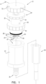
- Fig. 1 is a schematic cross-sectional illustration of a closed-system grinding syringe 10 for liquefying and delivering a solid dosage form 20, in accordance with an application of the present invention.
- Fig. 1 also shows an adapter 90, described hereinbelow.
- grinding means reducing to a powder comprising small (e.g., fine) particles, as by pounding, crushing, or pulverizing. Typically, the particle size is less than 2 mm.
- Figs. 2A-B are exploded schematic illustrations showing components of closed-system grinding syringe 10, in accordance with an application of the present invention.
- the components closed-system grinding syringe 10 may comprise a metal, such as stainless steel, and/or a polymer.
- FIG. 3 is a schematic cross-sectional view of closed-system grinding syringe 10, in accordance with an application of the present invention.
- solid dosage form 20 is shown in Figs. 1 , 2A-B , and 3 for illustrating the operation of closed-system grinding syringe 10.
- solid dosage form 20 is shown in Figs. 2A-B to illustrate the eventual location of solid dosage form 20; solid dosage form 20 is of course not inserted into closed-system grinding syringe 10 during manufacture of closed-system grinding syringe 10, but during use of the syringe by a healthcare worker after manufacture.
- closed-system grinding syringe 10 comprises:
- Plunger head 36 is insertable into and moveable within barrel 22 such that (a) a portion of barrel 22 defines a closed-system syringe chamber 46 between bottom barrel wall 28 and lower surface 40 of bottom plunger wall 38, and (b) that plunger-head annular seal 42 forms a plunger-head fluid-tight seal between an outer surface 44 of plunger head 36 and cylindrical inner surface 26 of barrel 22.
- plunger shaft 34 and plunger head 36 are arranged such that downward motion of plunger shaft 34 moves plunger head 36 downward within barrel 22.
- plunger 32 is non-integral with barrel 22, and separable from and coupleable to barrel 22 during normal use of closed-system grinding syringe 10.
- Fig. 1 shows plunger 32 separated from barrel 22
- Fig. 3 shows plunger 32 coupled to barrel 22 with plunger head 36 inserted into barrel 22.
- plunger 32 is integrated with barrel 22, in which case closed-system grinding syringe 10 is typically provided with plunger 32 maximally withdrawn from barrel, such that access is provided to grinding compartment 62, described hereinbelow.
- plunger shaft 34 has a smaller average outer diameter than does plunger head 36.
- closed-system grinding syringe 10 further comprises a barrel cap 50, which is configured to be attachable to top barrel opening 52 (such as by relative rotation) so as to form a barrel-cap fluid-tight seal with top barrel opening 52.
- Barrel cap 50 is shaped so as to define a cap opening 54 through barrel cap 50.
- Plunger shaft 34 is slidably disposed through cap opening 54 so as to form a plunger-head fluid-tight seal between plunger shaft 34 and a perimeter of cap opening 54 (such as by an annular seal 55, e.g., an O-ring).
- barrel cap 50 is fixed to plunger 32 such that plunger shaft 34 is slidably disposed through cap opening 54 and plunger 32 is not separable from barrel cap 50 during the normal use of closed-system grinding syringe 10.
- closed-system grinding syringe 10 further comprises a solid-dosage-form support disc 60, which is disposed below bottom plunger wall 38 so as to define a grinding compartment 62 between a lower surface 64 of bottom plunger wall 38 and an upper surface 66 of solid-dosage-form support disc 60.
- Solid-dosage-form support disc 60 is thus disposed within closed-system syringe chamber 46.
- Solid-dosage-form support disc 60 is shaped so as to define a plurality of holes 68 through solid-dosage-form support disc 60.
- holes 68 have an average diameter of at least 1 mm (e.g., at least 2 mm), no more than 5 mm, and/or between 1 mm (e.g., 2 mm) and 5 mm, and/or an average cross-sectional area of at least 0.8 cm2 (e.g., at least 3.1 mm2), no more than 20 mm2, and/or between 0.8 mm2 (e.g., 3.1 mm2) and 20 mm2.
- grinding compartment 62 is shaped so as to define one or more lateral openings 86 for insertion of solid dosage form 20 into grinding compartment 62 (insertion of plunger head 36 into barrel 22 typically causes cylindrical inner surface 26 of barrel 22 to partially or entirely obstruct the one or more lateral openings 86).
- the one or more lateral openings 86 are a single lateral opening that extends 360 degrees around grinding compartment 62.
- the one or more lateral openings 86 extend between 90 and 360 degrees around grinding compartment 62.
- grinding compartment 62 instead defines another type of opening, such as a door, window, or flap.
- closed-system grinding syringe 10 further comprises a knob 70.
- knob 70 is coupled to a top end of plunger shaft 34.
- closed-system grinding syringe 10 is configured such that knob 70 is activated by rotation thereof.
- plunger shaft 34 and plunger head 36 are typically arranged such that downward motion of plunger shaft 34 moves plunger head 36 downward within barrel 22; typically, knob 70 and plunger shaft 34 are arranged such that downward motion of knob 70 moves down plunger shaft 34, and thus plunger head 36.
- closed-system grinding syringe 10 is configured such that knob 70 is activated by axial movement of knob 70 (downward or upward) (configuration not shown).
- closed-system grinding syringe 10 is configured such that when (a) solid dosage form 20 is disposed in grinding compartment 62, (b) plunger head 36 is inserted into barrel 22, and (c) closed-system grinding syringe 10 is oriented upright (i.e., barrel cap 50 is disposed above bottom barrel wall 28), upon activation of knob 70, grinding compartment 62 grinds solid dosage form 20 to a powder 71 and at least 75 % (e.g., at least 95 % ) of powder 71 passes through the plurality of holes 68 into a portion 92 of closed-system syringe chamber 46 below solid-dosage-form support disc 60.
- lower surface 40 of bottom plunger wall 38 is shaped so as to define grinding protrusions 72.
- grinding protrusions 72 may comprise teeth, burrs, or an abraded surface.
- a protrusion support 81 may be provided that is shaped so as to define grinding protrusions 72, and to couple grinding protrusions 72 to plunger head 36, such that protrusion support 81 defines at least a portion of lower surface 40 of bottom plunger wall 38.
- lower surface 40 is shaped so as to define between 10 and 100 grinding protrusions 72.
- upper surface 66 of solid-dosage-form support disc 60 is shaped so as to define support-disc grinding protrusions, such as describe hereinbelow with reference to Figs. 7A-C and 8A-B .
- closed-system grinding syringe 10 is non-electrical and is configured such that when (a) solid dosage form 20 is disposed in grinding compartment 62, (b) plunger head 36 is inserted into barrel 22, and (c) closed-system grinding syringe 10 is oriented upright, upon mechanical activation of knob 70, grinding compartment 62 grinds solid dosage form 20.
- fluid port 30 comprises a valve 93.
- the valve may comprise one or more self-sealing membranes, e.g., comprising silicone, rubber, or any other suitable materials for sealing.
- closed-system grinding syringe 10 is configured to move lower surface 40 of bottom plunger wall 38 and upper surface 66 of solid-dosage-form support disc 60 closer to each other as grinding compartment 62 grinds solid dosage form 20.
- closed-system grinding syringe 10 may be configured to move upper surface 66 of solid-dosage form with respect to cylindrical inner surface 26 of barrel 22 as grinding compartment 62 grinds solid dosage form 20.
- closed-system grinding syringe 10 further comprises:
- upper surface 66 of solid-dosage-form support disc 60 does not rotate during upward movement of solid-dosage-form support disc 60 with respect to cylindrical inner surface 26 of barrel 22, i.e., is rotationally fixed with respect to lower surface 40 of bottom plunger wall 38 and with respect to cylindrical inner surface 26 of barrel 22 (as well as with respect to other components of closed-system grinding syringe 10).
- lower surface 40 of bottom plunger wall 38 typically does not rotate while lower surface 40 of bottom plunger wall 38 and upper surface 66 of solid-dosage-form support disc 60 move closer to each other as grinding compartment 62 grinds solid dosage form 20 by squeezing and squashing solid dosage form 20 between upper surface 66 of solid-dosage-form support disc 60 and lower surface 40 of bottom plunger wall 38; i.e., lower surface 40 of bottom plunger wall 38 is rotationally fixed with respect to upper surface 66 of solid-dosage-form support disc 60 (as well as with respect to other components of closed-system grinding syringe 10).
- axially-moveable shaft 94 may be rotationally-fixed with respect to plunger shaft 34 by one or more set screws 58 that engage one or more corresponding axial depressions 59 defined by an outer surface of axially-moveable shaft 94.
- Alternative ways of rotationally fixing axially-moveable shaft 94 with respect to plunger shaft 34 will readily be apparent to those skilled in the art who have read the present application.
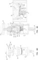
- FIGs. 4A-L are schematic illustrations of a method of using closed-system grinding syringe 10 for liquefying and delivering solid dosage form 20, in accordance with an application of the present invention.
- the method begins with the receipt of closed-system grinding syringe 10 by the healthcare worker, optionally with plunger head 36 pre-inserted into barrel 22. Alternatively, the syringe is packaged with plunger head 36 separate from barrel 22. If plunger head 36 is received pre-inserted into barrel 22, the healthcare worker removes plunger head 36 from barrel 22.
- solid dosage form 20 may comprise one or more drug pills, drug capsule, or any other solid dosage form.
- the healthcare worker inserts (a) plunger head 36 into barrel 22 such that a portion of barrel 22 defines closed-system syringe chamber 46 between bottom barrel wall 28 and lower surface 40 of bottom plunger wall 38, and (b) attaches barrel cap 50 to top barrel opening 52 so as to form a barrel-cap fluid-tight seal with top barrel opening 52.
- Solid dosage form 20 is not yet ground into powder 71 at this step of the method.
- knob 70 (such as by rotation) such that grinding compartment 62 grinds solid dosage form 20 to powder 71 and at least 75% (e.g., at least 95%) of powder 71 passes through the plurality of holes 68 into portion 92 of closed-system syringe chamber 46 below solid-dosage-form support disc 60.
- the healthcare worker introduces (e.g., injects) a liquid 73 into closed-system syringe chamber 46 via fluid port 30.
- fluid port 30 is configured to mate with a tip of a syringe 75 (separate from closed-system grinding syringe 10), for introducing liquid 73 into closed-system syringe chamber 46 via fluid port 30.
- fluid port 30 may be shaped so as to define a female-taper fitting, such as a Luer lock or a Luer taper, as are known in the art.
- powder 71 is mixed with liquid 73 to form a mixture 77 (e.g., a solution or a suspension), such as by shaking closed-system grinding syringe 10.
- a mixture 77 e.g., a solution or a suspension
- powder 71 is loose at the bottom of closed-system syringe chamber 46, which facilitates mixing more readily than if, for example, powder 71 were crushed into a cake during the grinding process.
- all or a portion of powder 71 that may have remained above solid-dosage-form support disc 60 during grinding as described hereinabove with reference to Fig.
- the healthcare worker delivers mixture 77 via fluid port 30 by moving plunger head 36 downward within barrel 22.
- bottom barrel wall 28 is shaped as a funnel (typically a shallow funnel), similar to the bottom surface of conventional syringe chambers, in order to allow more thorough delivery of mixture 77 from barrel 22 to fluid port 30.
- the bottom surface of solid-dosage-form support disc 60 is slightly convex (e.g., inverse-funnel shaped), similar to the bottom surface of a conventional syringe plunger, in order to fit snugly into the funnel-shaped bottom barrel wall 28 and increase delivery of mixture 77 from barrel 22.
- fluid port 30 is configured to mate with a feeding tube, for delivering mixture 77 via fluid port 30.
- the feeding tube may be a universal feeding tube, a percutaneous endoscopic gastrostomy (PEG) tube, a gastrostomy tube, or a nasogastric feeding tube.
- PEG percutaneous endoscopic gastrostomy
- gastrostomy tube a gastrostomy tube
- nasogastric feeding tube nasogastric feeding tube.
- mixture 77 may be delivered the patient's mouth, without a feeding tube.
- closed-system grinding syringe 10 may be useful for liquifying solid drug forms for patients who cannot swallow solid drugs.
- a system comprising closed-system grinding syringe 10 and adapter 90, which is configured to be sealingly coupled to fluid port 30 and to a feeding tube.
- the feeding tube may be a universal feeding tube, a percutaneous endoscopic gastrostomy (PEG) tube, a gastrostomy tube, or a nasogastric feeding tube.
- PEG percutaneous endoscopic gastrostomy
- gastrostomy tube a gastrostomy tube
- a nasogastric feeding tube nasogastric feeding tube.
- mixture 77 may be delivered the patient's mouth, without a feeding tube.
- closed-system grinding syringe 10 is shaped so as to define:
- liquid channel 74 has a greater average inner diameter than does gas channel 78.
- barrel 22 is shaped so as to define an upper compartment 82 between barrel cap 50 and bottom plunger wall 38, at least when barrel cap 50 is attached to top barrel opening 52.
- Upper compartment 82 is fluid-isolated from closed-system syringe chamber 46 and from the external environment.
- at least a portion of (e.g., an entirety of) upper compartment 82 is located within plunger head 36.
- second liquid-channel opening 76 of liquid channel 74 is in fluid communication with closed-system syringe chamber 46 through bottom barrel wall 28, and gas channel 78 has a second gas-channel opening 84 in fluid communication with upper compartment 82.
- liquid channel 74 and gas channel 78 enables, for the introduction of liquid 73 into closed-system syringe chamber 46 via fluid port 30 described hereinabove with reference to Figs. 4H-I , the mating of fluid port 30 with a tip of a dual-needle closed-pressure equalization syringe comprising needles 79A and 79B, such that two needles of the dual-needle closed-pressure equalization syringe are in fluid communication with liquid channel 74 and gas channel 78, respectively, via fluid port 30.
- a dual-needle closed-pressure equalization syringe allows the injection of liquid 73 from a liquid compartment of the dual-needle closed-pressure equalization syringe into liquid channel 74 and the simultaneous return of gas from gas channel 78 into a separate gas compartment in the dual-needle closed-pressure equalization syringe.
- FIG. 5 is a schematic illustration of a closed-system grinding syringe 110 for liquefying and delivering solid dosage form 20, in accordance with an application of the present invention.
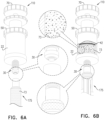
- Figs. 6A-B are schematic illustrations of a portion of a method of using closed-system grinding syringe 110 for liquefying and delivering solid dosage form 20, in accordance with an application of the present invention.
- closed-system grinding syringe 110 may be identical to closed-system grinding syringe 10, described hereinabove with reference to Figs. 1-4L , may be used in the same manner, and may implement any of the features thereof described herein.
- closed-system grinding syringe 10 is not shaped so as to define gas channel 78.
- the healthcare worker introduces (e.g., injects) liquid 73 into closed-system syringe chamber 46 via fluid port 30 by mating a tip of a single-channel syringe 175 (which is separate from closed-system grinding syringe 10, and is typically conventional).
- fluid port 30 may be shaped so as to define a female-taper fitting, such as a Luer lock or a Luer taper
- syringe 175 may be shaped so as to define a male-taper fitting, such as a Luer lock or a Luer taper, as are known in the art.
- the air in closed-system syringe chamber 46 prior to introduction of liquid 73 is sufficiently compressible such that the force necessary to introduce liquid 73 can be readily applied manually by the healthcare worker.
- Figs. 7A-C are schematic illustrations of alternative configurations of components of closed-system grinding syringe 10 or 110, in accordance with an application of the present invention.
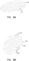
- Figs. 8A and 8B are schematic illustrations of a protrusion support 281 and a solid-dosage-form support disc 360, in accordance with respective applications of the present invention.
- protrusion support 281 is provided that is shaped so as to define grinding protrusions 272, and to couple grinding protrusions 272 to plunger head 36, such that protrusion support 281 defines at least a portion of lower surface 40 of bottom plunger wall 38.
- protrusion support 281 replaces protrusion support 81, described hereinabove with reference to Figs. 2A-B and 3 .
- closed-system grinding syringe 10 comprises solid-dosage-form support disc 360, instead of solid-dosage-form support disc 60.
- Solid-dosage-form support disc 360 is shaped so as to define a plurality of holes 368 through solid-dosage-form support disc 360.
- Holes 368 are aligned with respective grinding protrusions 272, such that grinding protrusions 272 at least partially enter respective holes 368 when solid-dosage-form support disc 360 moves closer to lower surface 40 of bottom plunger wall 38 (and thus closer to grinding protrusions 272).
- This alignment can perhaps be best seen in Fig. 7C , which is a bottom-view of support disc 360, in which grinding protrusions 272 can be seen partially inserted into respective holes 368.
- This alignment allows solid-dosage-form support disc 360 to move close to protrusion support 281 (and lower surface 40 of bottom plunger wall 38), thereby increasing the strength of grinding of solid dosage form 20.
- holes 368 have a diameter of at least 0.2 mm, no more than 0.6 mm, and/or between 0.2 and 0.6 mm, such as 0.4 mm.
- an upper surface 366 of solid-dosage-form support disc 360 is shaped so as to define support-disc grinding protrusions 370, which are not aligned with (i.e., do not overlap with) grinding protrusions 272, such that the two sets of grinding protrusions are interspersed with each other and increase the strength of grinding of solid dosage form 20.
- solid-dosage-form support disc 360 is not shaped so as to define any grinding protrusions.
- closed-system grinding syringe 10 is configured such that upper surface 366 of solid-dosage-form support disc 360 (including support-disc grinding protrusions 370, if provided) and lower surface 40 of bottom plunger wall 38 (grinding protrusions 272) (lower surface 40 is defined at least in part by the lower surface of protrusion support 281) can come very close to each other, typically touch each other, if not blocked by remnants of solid dosage form 20 that fail to pass through holes 368.
Landscapes
- Health & Medical Sciences (AREA)
- Life Sciences & Earth Sciences (AREA)
- Veterinary Medicine (AREA)
- Public Health (AREA)
- General Health & Medical Sciences (AREA)
- Animal Behavior & Ethology (AREA)
- Biomedical Technology (AREA)
- Hematology (AREA)
- Heart & Thoracic Surgery (AREA)
- Anesthesiology (AREA)
- Engineering & Computer Science (AREA)
- Vascular Medicine (AREA)
- Nutrition Science (AREA)
- Chemical & Material Sciences (AREA)
- Medicinal Chemistry (AREA)
- Pharmacology & Pharmacy (AREA)
- Infusion, Injection, And Reservoir Apparatuses (AREA)
Description
- The present invention relates generally to techniques for preparation of oral dosage forms.
- A closed system drug transfer device (CSTD) is a drug transfer device that mechanically prohibits the transfer of environmental contaminants into the system and the escape of hazardous drug or vapor concentrations outside the system.
- The U.S. National Institute for Occupational Safety and Health (NIOSH) has provided the following definitions of a closed system drug transfer device (CSTD):
- "a drug-transfer device that mechanically prohibits the transfer of environmental contaminants into the system and the escape of hazardous drug or vapor concentrations outside the system" (NIOSH 2004).
- "A drug containment device is one that is both airtight and leakproof."
- Commercially available CSTDs for liquid dosage form products include the following: BD PhaSealTM (Becton, Dickinson), Tevadaptor (Teva, Israel), Halo (Corvida, USA), ChemoClave (ICUmed, USA), Equashield II (Equashield, USA), and NeoShield® (JMS, Japan & USA). Other closed system drug transfer devices are known from
CN 208 436 090 U andUS 5 472 421 A . - In some common techniques for liquifying solid drug forms, the solid drug form is crushed and diluted in a vessel open to the environment, which may cause the work environment to be contaminated with carcinogenic or teratogenic substances, which might expose and endanger the medical staff to hazardous substances in the course of their duties as providers of medical care.
- Embodiments of the present invention provide a closed transfer system for solid oral dosage forms, which is configured to crush and liquefy solid oral drugs, such as solid cytotoxic drugs. The system performs the crushing and liquefaction under full sealing conditions, without allowing release of solid, liquid, or gaseous forms of the drug to the external environment, which might jeopardize the health of the attending healthcare workers. They system also mechanically prevents the transfer of environmental contaminants into the system.
- Typically, the system is designed for single use, in order to obviate the need for complex cleaning of the system between operations, and to prevent cross-contamination between different drugs.
- There is therefore provided, in accordance with an application of the present invention, apparatus including a closed-system grinding syringe for liquefying and delivering a solid dosage form, the closed-system grinding syringe including:
- a barrel, which is shaped so as to define (a) a lateral wall shaped so as to define a cylindrical inner surface, (b) a top barrel opening, and (c) a bottom barrel wall;
- a fluid port disposed on the bottom barrel wall;
- a plunger, which includes a (a) plunger shaft; (b) a plunger head shaped so as to define a bottom plunger wall shaped so as to define a lower surface; and (c) a plunger-head annular seal, wherein the plunger head is insertable into and moveable within the barrel such that (a) a portion of the barrel defines a closed-system syringe chamber between the bottom barrel wall and the lower surface of the bottom plunger wall, and (b) the plunger-head annular seal forms a plunger-head fluid-tight seal between an outer surface of the plunger head and the cylindrical inner surface of the barrel;
- a barrel cap, which is (a) configured to be attachable to the top barrel opening so as to form a barrel-cap fluid-tight seal with the top barrel opening, and (b) shaped so as to define a cap opening through the barrel cap, wherein the plunger shaft is slidably disposed through the cap opening so as to form a plunger-head fluid-tight seal between the plunger shaft and a perimeter of the cap opening;
- a solid-dosage-form support disc, which (a) is disposed below the bottom plunger wall so as to define a grinding compartment between the lower surface of the bottom plunger wall and an upper surface of the solid-dosage-form support disc, and (b) is shaped so as to define a plurality of holes through the solid-dosage-form support disc; and
- a knob,
- wherein the closed-system grinding syringe is configured such that when (a) the solid dosage form is disposed in the grinding compartment, (b) the plunger head is inserted into the barrel, and (c) the closed-system grinding syringe is oriented upright, upon activation of the knob, the grinding compartment grinds the solid dosage form to a powder and at least 75% of the powder passes through the plurality of holes into a portion of the closed-system syringe chamber below the solid-dosage-form support disc.
- For some applications, the closed-system grinding syringe is non-electrical and is configured such that when (a) the solid dosage form is disposed in the grinding compartment, (b) the plunger head is inserted into the barrel, and (c) the closed-system grinding syringe is oriented upright, upon mechanical activation of the knob, the grinding compartment grinds the solid dosage form.
- For some applications, the lower surface of the bottom plunger wall is shaped so as to define grinding protrusions. For some of these applications, the holes of the solid-dosage-form support disc are aligned with the grinding protrusions, such that the grinding protrusions at least partially enter respective holes when the solid-dosage-form support disc moves closer to the lower surface of the bottom plunger wall. Alternatively or additionally, for some of these applications, the grinding protrusions are bottom-plunger-wall grinding protrusions, and the upper surface of the solid-dosage-form support disc is shaped so as to define support-disc grinding protrusions, which are not aligned with the bottom-plunger-wall grinding protrusions.
- For some applications, the upper surface of the solid-dosage-form support disc is shaped so as to define support-disc grinding protrusions.
- For some applications, the closed-system grinding syringe is configured such that the knob is activated by rotation thereof.
- For some applications, the plunger shaft has a smaller average outer diameter than does the plunger head.
- For some applications, the plunger is non-integral with the barrel, and separable from and coupleable to the barrel during normal use of the closed-system grinding syringe.
- For some applications, the barrel cap is fixed to the plunger such that the plunger shaft is slidably disposed through the cap opening and the plunger is not separable from the barrel cap during the normal use of the closed-system grinding syringe.
- For some applications, the plunger-head annular seal includes an O-ring.
- For some applications, the fluid port includes a valve.
- For some applications, the closed-system grinding syringe is configured to move the lower surface of the bottom plunger wall and the upper surface of the solid-dosage-form support disc closer to each other as the grinding compartment grinds the solid dosage form.
- For some applications, the closed-system grinding syringe is configured such that the lower surface of the bottom plunger wall does not rotate while the lower surface of the bottom plunger wall and the upper surface of the solid-dosage-form support disc move closer to each other as the grinding compartment grinds the solid dosage form.
- For some applications, the closed-system grinding syringe is configured to move the upper surface of the solid-dosage-form support disc with respect to the cylindrical inner surface of the barrel as the grinding compartment grinds the solid dosage form.
- For some applications, the closed-system grinding syringe is configured such that the upper surface of the solid-dosage-form support disc does not rotate during upward movement of the dosage-form support disc with respect to the cylindrical inner surface of the barrel.
- For some applications:
- the closed-system grinding syringe further includes:
- an axially-moveable shaft, which (a) is disposed partially within the plunger shaft, (b) forms a fluid-tight seal with an inner surface of the plunger shaft, (c) is connected to the solid-dosage-form support disc, (d) is rotationally-fixed with respect to the plunger shaft, and (e) is shaped so as to define an inner space having an internally-threaded wall; and
- an externally-threaded stem, which is (a) disposed partially within the plunger shaft, (b) axially fixed with respect to the plunger shaft, and (c) connected to the knob, and
- an external thread of the externally-threaded stem is mated with an internal thread of the internally-threaded wall, such that rotation of the externally-threaded stem in one rotational direction causes upward axial movement of the axially-moveable shaft with respect to the plunger shaft, which in turn moves the upper surface of the solid-dosage-form support disc upward with respect to the cylindrical inner surface of the barrel, causing the grinding compartment to grind the solid dosage form.
- For some applications, the closed-system grinding syringe is shaped so as to define a liquid channel having (a) a first liquid-channel opening in fluid communication with the fluid port and (b) a second liquid-channel opening in fluid communication with the closed-system syringe chamber.
- For some applications, the closed-system grinding syringe is shaped so as to define:
- a liquid channel having (a) a first liquid-channel opening in fluid communication with the fluid port and (b) a second liquid-channel opening in fluid communication with the closed-system syringe chamber, and
- a gas channel having a first gas-channel opening in fluid communication with the fluid port.
- For some applications:
- the barrel is shaped so as to define an upper compartment between the barrel cap and the bottom plunger wall, when the barrel cap is attached to the top barrel opening, wherein the upper compartment is fluid-isolated from the closed-system syringe chamber and the external environment,
- the liquid channel has a second liquid-channel opening in fluid communication with the closed-system syringe chamber through the bottom barrel wall, and
- the gas channel has a second gas-channel opening in fluid communication with the upper compartment.
- For some applications, at least a portion of the upper compartment is located within the plunger head.
- For some applications, the liquid channel has a greater average inner diameter than does the gas channel.
- For some applications, the grinding compartment is shaped so as to define one or more lateral openings for insertion of the solid dosage form into the grinding compartment.
- For some applications, the one or more lateral openings are a single lateral opening that extends 360 degrees around the grinding compartment.
- For some applications, the one or more lateral openings extend between 90 and 360 degrees around the grinding compartment.
- For some applications, the fluid port is configured to mate with a tip of a syringe.
- For some applications, the fluid port is shaped so as to define a female-taper fitting.
- For some applications, the fluid port is configured to mate with a feeding tube.
- For some applications, the feeding tube is selected from the group consisting of: a universal feeding tube, a percutaneous endoscopic gastrostomy (PEG) tube, a gastrostomy tube, and a nasogastric feeding tube.
- For some applications, the apparatus further includes an adapter, which is configured to be sealingly coupled to the fluid port and to the feeding tube.
- For some applications, the feeding tube is selected from the group consisting of: a universal feeding tube, a percutaneous endoscopic gastrostomy (PEG) tube, a gastrostomy tube, and a nasogastric feeding tube.
- There is further provided, in accordance with an application of the present invention, a method of liquefying and delivering a solid dosage form, the method including:
- providing a closed-system grinding syringe including:
- a barrel, which is shaped so as to define (a) a lateral wall shaped so as to define a cylindrical inner surface, (b) a top barrel opening, and (c) a bottom barrel wall;
- a fluid port disposed on the bottom barrel wall;
- a plunger, which includes (a) a plunger shaft; (b) a plunger head shaped so as to define a bottom plunger wall shaped so as to define a lower surface; and (c) a plunger-head annular seal;
- a barrel cap, which is shaped so as to define a cap opening through the barrel cap, wherein the plunger shaft is slidably disposed through the cap opening so as to form a plunger-head fluid-tight seal between the plunger shaft and a perimeter of the cap opening;
- a solid-dosage-form support disc, which (a) is disposed below the bottom plunger wall so as to define a grinding compartment between the lower surface of the bottom plunger wall and an upper surface of the solid-dosage-form support disc, and (b) is shaped so as to define a plurality of holes through the solid-dosage-form support disc; and
- a knob;
- inserting the solid dosage form into the grinding compartment;
- thereafter, inserting the plunger head into the barrel such that (a) a portion of the barrel defines a closed-system syringe chamber between the bottom barrel wall and the lower surface of the bottom plunger wall, (b) the plunger-head annular seal forms a plunger-head fluid-tight seal between an outer surface of the plunger head and the cylindrical inner surface of the barrel;
- thereafter, attaching the barrel cap to the top barrel opening so as to form a barrel-cap fluid-tight seal with the top barrel opening;
- thereafter, while the closed-system grinding syringe is oriented upright, activating the knob such that the grinding compartment grinds the solid dosage form to a powder and at least 75% of the powder passes through the plurality of holes into a portion of the closed-system syringe chamber below the solid-dosage-form support disc;
- thereafter, introducing a liquid into the closed-system syringe chamber via the fluid port;
- thereafter, mixing the powder with the liquid to form a mixture; and
- thereafter, delivering the mixture via the fluid port by moving the plunger head downward within the barrel.
- For some applications, introducing the liquid into the closed-system syringe chamber via the fluid port including coupling a syringe to the fluid port and injecting the liquid from the syringe into the closed-system syringe chamber via the fluid port.
- For some applications, the closed-system grinding syringe is configured to move the lower surface of the bottom plunger wall and the upper surface of the solid-dosage-form support disc closer to each other as the grinding compartment grinds the solid dosage form.
- For some applications, the closed-system grinding syringe is configured such that the lower surface of the bottom plunger wall does not rotate while the lower surface of the bottom plunger wall and the upper surface of the solid-dosage-form support disc move closer to each other as the grinding compartment grinds the solid dosage form.
- For some applications, the closed-system grinding syringe is configured to move the upper surface of the solid-dosage-form support disc with respect to the cylindrical inner surface of the barrel as the grinding compartment grinds the solid dosage form.
- For some applications, the closed-system grinding syringe is configured such that the upper surface of the solid-dosage-form support disc does not rotate during upward movement of the dosage-form support disc with respect to the cylindrical inner surface of the barrel.
- For some applications, activating the knob includes rotating the knob.
- For some applications, the closed-system grinding syringe is shaped so as to define a liquid channel having (a) a first liquid-channel opening in fluid communication with the fluid port and (b) a second liquid-channel opening in fluid communication with the closed-system syringe chamber.
- For some applications:
- the closed-system grinding syringe is shaped so as to define (a) a liquid channel having (i) a first liquid-channel opening in fluid communication with the fluid port and (ii) a second liquid-channel opening in fluid communication with the closed-system syringe chamber, and (b) a gas channel having a first gas-channel opening in fluid communication with the fluid port, and
- introducing the liquid into the closed-system syringe chamber via the fluid port includes coupling two needles of a dual-needle closed-pressure equalization syringe in fluid communication with the liquid channel and the gas channel, respectively, via the fluid port.
- For some applications:
- the barrel is shaped so as to define an upper compartment between the barrel cap and the bottom plunger wall, when the barrel cap is attached to the top barrel opening, wherein the upper compartment is fluid-isolated from the closed-system syringe chamber and the external environment,
- the liquid channel has a second liquid-channel opening in fluid communication with the closed-system syringe chamber through the bottom barrel wall, and
- the gas channel has a second gas-channel opening in fluid communication with the upper compartment.
- For some applications, at least a portion of the upper compartment is located within the plunger head.
- For some applications, the liquid channel has a greater average inner diameter than does the gas channel.
- For some applications, the grinding compartment is shaped so as to define one or more lateral openings, and inserting the solid dosage form into the grinding compartment includes inserting the solid dosage form via the one or more lateral openings.
- For some applications, delivering the mixture includes coupling the fluid port to a feeding tube and delivery the mixture to the feeding tube.
- For some applications, the feeding tube is selected from the group consisting of: a universal feeding tube, a percutaneous endoscopic gastrostomy (PEG) tube, a gastrostomy tube, and a nasogastric feeding tube.
- For some applications, delivering the mixture includes sealingly coupling an adapter to the fluid port and to the feeding tube.
- For some applications, the feeding tube is selected from the group consisting of: a universal feeding tube, a percutaneous endoscopic gastrostomy (PEG) tube, a gastrostomy tube, and a nasogastric feeding tube.
- The present invention will be more fully understood from the following detailed description of embodiments thereof, taken together with the drawings, in which:
-
-
Fig. 1 is a schematic cross-sectional illustration of a closed-system grinding syringe for liquefying and delivering a solid dosage form, in accordance with an application of the present invention; -
Figs. 2A-B are exploded schematic illustrations showing components of the closed-system grinding syringe ofFig. 1 , in accordance with an application of the present invention; -
Fig. 3 is a schematic cross-sectional view of the closed-system grinding syringe ofFig. 1 , in accordance with an application of the present invention; -
Figs. 4A-L are schematic illustrations of a method of using the closed-system grinding syringe ofFig. 1 for liquefying and delivering a solid dosage form, in accordance with an application of the present invention; -
Fig. 5 is a schematic illustration of another closed-system grinding syringe for liquefying and delivering a solid dosage form, in accordance with an application of the present invention; -
Figs. 6A-B are schematic illustrations of a portion of a method of using the closed - system grinding syringe ofFig. 5 for liquefying and delivering the solid dosage form, in accordance with an application of the present invention; -
Figs. 7A-C are schematic illustrations of alternative configurations of components of the closed-system grinding syringe ofFig. 1 orFig. 5 , in accordance with an application of the present invention; and -
Figs. 8A and 8B are schematic illustrations of a protrusion support and a solid-dosage-form support disc of the components ofFigs. 7A-C , in accordance with respective applications of the present invention. - Reference is made to
Fig. 1 , which is a schematic cross-sectional illustration of a closed-system grinding syringe 10 for liquefying and delivering asolid dosage form 20, in accordance with an application of the present invention.Fig. 1 also shows anadapter 90, described hereinbelow. As used in the present application, including in the claims, "grinding" means reducing to a powder comprising small (e.g., fine) particles, as by pounding, crushing, or pulverizing. Typically, the particle size is less than 2 mm. - Reference is also made to
Figs. 2A-B , which are exploded schematic illustrations showing components of closed-system grinding syringe 10, in accordance with an application of the present invention. The components closed-system grinding syringe 10 may comprise a metal, such as stainless steel, and/or a polymer. - Reference is further made to
Fig. 3 , which is a schematic cross-sectional view of closed-system grinding syringe 10, in accordance with an application of the present invention. Although not a component of closed-system grinding syringe 10,solid dosage form 20 is shown inFigs. 1 ,2A-B , and3 for illustrating the operation of closed-system grinding syringe 10. In particular,solid dosage form 20 is shown inFigs. 2A-B to illustrate the eventual location ofsolid dosage form 20;solid dosage form 20 is of course not inserted into closed-system grinding syringe 10 during manufacture of closed-system grinding syringe 10, but during use of the syringe by a healthcare worker after manufacture. - Typically, closed-
system grinding syringe 10 comprises: - a
barrel 22, which is shaped so as to define (a) alateral wall 24 shaped so as to define a cylindricalinner surface 26, (b) a top barrel opening 52, and (c) abottom barrel wall 28; - a
fluid port 30 disposed onbottom barrel wall 28; and - a
plunger 32, which comprises (a) aplunger shaft 34; (b) aplunger head 36 shaped so as to define abottom plunger wall 38 shaped so as to define alower surface 40; and (c) a plunger-head annular seal 42 (comprising, for example, an O-ring or another resiliently elastic seal). -
Plunger head 36 is insertable into and moveable withinbarrel 22 such that (a) a portion ofbarrel 22 defines a closed-system syringe chamber 46 betweenbottom barrel wall 28 andlower surface 40 ofbottom plunger wall 38, and (b) that plunger-headannular seal 42 forms a plunger-head fluid-tight seal between anouter surface 44 ofplunger head 36 and cylindricalinner surface 26 ofbarrel 22. Typically,plunger shaft 34 andplunger head 36 are arranged such that downward motion ofplunger shaft 34moves plunger head 36 downward withinbarrel 22. - For some applications,
plunger 32 is non-integral withbarrel 22, and separable from and coupleable tobarrel 22 during normal use of closed-system grinding syringe 10.Fig. 1 (as well asFigs. 4A-B ) showsplunger 32 separated frombarrel 22, whileFig. 3 (as well asFigs. 4C-L ) showsplunger 32 coupled tobarrel 22 withplunger head 36 inserted intobarrel 22. Alternatively,plunger 32 is integrated withbarrel 22, in which case closed-system grinding syringe 10 is typically provided withplunger 32 maximally withdrawn from barrel, such that access is provided to grindingcompartment 62, described hereinbelow. - Typically,
plunger shaft 34 has a smaller average outer diameter than doesplunger head 36. - Typically, closed-
system grinding syringe 10 further comprises abarrel cap 50, which is configured to be attachable to top barrel opening 52 (such as by relative rotation) so as to form a barrel-cap fluid-tight seal with top barrel opening 52.Barrel cap 50 is shaped so as to define acap opening 54 throughbarrel cap 50.Plunger shaft 34 is slidably disposed throughcap opening 54 so as to form a plunger-head fluid-tight seal betweenplunger shaft 34 and a perimeter of cap opening 54 (such as by anannular seal 55, e.g., an O-ring). Typically,barrel cap 50 is fixed toplunger 32 such thatplunger shaft 34 is slidably disposed throughcap opening 54 andplunger 32 is not separable frombarrel cap 50 during the normal use of closed-system grinding syringe 10. - Typically, closed-
system grinding syringe 10 further comprises a solid-dosage-form support disc 60, which is disposed belowbottom plunger wall 38 so as to define a grindingcompartment 62 between alower surface 64 ofbottom plunger wall 38 and anupper surface 66 of solid-dosage-form support disc 60. (Solid-dosage-form support disc 60 is thus disposed within closed-system syringe chamber 46.) Solid-dosage-form support disc 60 is shaped so as to define a plurality ofholes 68 through solid-dosage-form support disc 60. (Because of theseholes 68, solid-dosage-form support disc 60 does not meaningfully disturb the fluid continuity of closed-system syringe chamber 46.) Typically, holes 68 have an average diameter of at least 1 mm (e.g., at least 2 mm), no more than 5 mm, and/or between 1 mm (e.g., 2 mm) and 5 mm, and/or an average cross-sectional area of at least 0.8 cm2 (e.g., at least 3.1 mm2), no more than 20 mm2, and/or between 0.8 mm2 (e.g., 3.1 mm2) and 20 mm2. - Typically, grinding
compartment 62 is shaped so as to define one or morelateral openings 86 for insertion ofsolid dosage form 20 into grinding compartment 62 (insertion ofplunger head 36 intobarrel 22 typically causes cylindricalinner surface 26 ofbarrel 22 to partially or entirely obstruct the one or more lateral openings 86). For some applications, as shown, the one or morelateral openings 86 are a single lateral opening that extends 360 degrees around grindingcompartment 62. Alternatively, for some applications, the one or morelateral openings 86 extend between 90 and 360 degrees around grindingcompartment 62. Alternatively, grindingcompartment 62 instead defines another type of opening, such as a door, window, or flap. - Typically, closed-
system grinding syringe 10 further comprises aknob 70. Typically,knob 70 is coupled to a top end ofplunger shaft 34. For some applications, closed-system grinding syringe 10 is configured such thatknob 70 is activated by rotation thereof. As mentioned above,plunger shaft 34 andplunger head 36 are typically arranged such that downward motion ofplunger shaft 34moves plunger head 36 downward withinbarrel 22; typically,knob 70 andplunger shaft 34 are arranged such that downward motion ofknob 70 moves downplunger shaft 34, and thusplunger head 36. Alternatively, for some applications, closed-system grinding syringe 10 is configured such thatknob 70 is activated by axial movement of knob 70 (downward or upward) (configuration not shown). - For some applications, closed-
system grinding syringe 10 is configured such that when (a)solid dosage form 20 is disposed in grindingcompartment 62, (b)plunger head 36 is inserted intobarrel 22, and (c) closed-system grinding syringe 10 is oriented upright (i.e.,barrel cap 50 is disposed above bottom barrel wall 28), upon activation ofknob 70, grindingcompartment 62 grindssolid dosage form 20 to apowder 71 and at least 75% (e.g., at least 95%) ofpowder 71 passes through the plurality ofholes 68 into aportion 92 of closed-system syringe chamber 46 below solid-dosage-form support disc 60. - For some applications,
lower surface 40 ofbottom plunger wall 38 is shaped so as to define grindingprotrusions 72. For example, grindingprotrusions 72 may comprise teeth, burrs, or an abraded surface. Aprotrusion support 81 may be provided that is shaped so as to define grindingprotrusions 72, and to couple grindingprotrusions 72 toplunger head 36, such thatprotrusion support 81 defines at least a portion oflower surface 40 ofbottom plunger wall 38. For some applications,lower surface 40 is shaped so as to define between 10 and 100 grindingprotrusions 72. Alternatively or additionally, for some applications,upper surface 66 of solid-dosage-form support disc 60 is shaped so as to define support-disc grinding protrusions, such as describe hereinbelow with reference toFigs. 7A-C and8A-B . - Typically, closed-
system grinding syringe 10 is non-electrical and is configured such that when (a)solid dosage form 20 is disposed in grindingcompartment 62, (b)plunger head 36 is inserted intobarrel 22, and (c) closed-system grinding syringe 10 is oriented upright, upon mechanical activation ofknob 70, grindingcompartment 62 grindssolid dosage form 20. - For some applications,
fluid port 30 comprises avalve 93. For example, the valve may comprise one or more self-sealing membranes, e.g., comprising silicone, rubber, or any other suitable materials for sealing. - For some applications, closed-
system grinding syringe 10 is configured to movelower surface 40 ofbottom plunger wall 38 andupper surface 66 of solid-dosage-form support disc 60 closer to each other as grindingcompartment 62 grindssolid dosage form 20. For example, closed-system grinding syringe 10 may be configured to moveupper surface 66 of solid-dosage form with respect to cylindricalinner surface 26 ofbarrel 22 as grindingcompartment 62 grindssolid dosage form 20. - For some applications, closed-
system grinding syringe 10 further comprises: - an axially-
moveable shaft 94, which (a) is disposed partially withinplunger shaft 34, (b) forms a fluid-tight seal with aninner surface 48 of plunger shaft 34 (such as by anannular seal 56, e.g., an O-ring), (c) is connected to solid-dosage-form support disc 60, such as by one ormore connection arms 96, e.g., threeconnection arms 96, (d) is rotationally-fixed with respect toplunger shaft 34, and (e) is shaped so as to define an inner space having an internally-threadedwall 98; and - an externally-threaded
stem 99, which is (a) disposed partially withinplunger shaft 34, (b) axially fixed with respect toplunger shaft 34, and (c) connected toknob 70. The external thread of externally-threadedstem 99 is mated with the internal thread of internally-threadedwall 98, such that rotation of externally-threadedstem 99 in one rotational direction (e.g., clockwise) (such as by rotation of knob 70) causes upward axial movement of axially-moveable shaft 94 with respect toplunger shaft 34, which in turn movesupper surface 66 of solid-dosage-form support disc 60 upward with respect to cylindricalinner surface 26 ofbarrel 22, causing grindingcompartment 62 to grindsolid dosage form 20 by squeezing and squashingsolid dosage form 20 betweenupper surface 66 of solid-dosage-form support disc 60 andlower surface 40 ofbottom plunger wall 38. It is noted that a relatively large amount of force is applied tosolid dosage form 20 by this rotational arrangement. Typically, closed-system grinding syringe 10 is configured such thatupper surface 66 of solid-dosage-form support disc 60 andlower surface 40 ofbottom plunger wall 38 can come very close to each other, typically touch each other, if not blocked by remnants ofsolid dosage form 20 that fail to pass through holes 68. - Typically,
upper surface 66 of solid-dosage-form support disc 60 does not rotate during upward movement of solid-dosage-form support disc 60 with respect to cylindricalinner surface 26 ofbarrel 22, i.e., is rotationally fixed with respect tolower surface 40 ofbottom plunger wall 38 and with respect to cylindricalinner surface 26 of barrel 22 (as well as with respect to other components of closed-system grinding syringe 10). In addition,lower surface 40 ofbottom plunger wall 38 typically does not rotate whilelower surface 40 ofbottom plunger wall 38 andupper surface 66 of solid-dosage-form support disc 60 move closer to each other as grindingcompartment 62 grindssolid dosage form 20 by squeezing and squashingsolid dosage form 20 betweenupper surface 66 of solid-dosage-form support disc 60 andlower surface 40 ofbottom plunger wall 38; i.e.,lower surface 40 ofbottom plunger wall 38 is rotationally fixed with respect toupper surface 66 of solid-dosage-form support disc 60 (as well as with respect to other components of closed-system grinding syringe 10). - For example, axially-
moveable shaft 94 may be rotationally-fixed with respect toplunger shaft 34 by one ormore set screws 58 that engage one or more correspondingaxial depressions 59 defined by an outer surface of axially-moveable shaft 94. Alternative ways of rotationally fixing axially-moveable shaft 94 with respect toplunger shaft 34 will readily be apparent to those skilled in the art who have read the present application. - Reference is now made to
Figs. 4A-L , which are schematic illustrations of a method of using closed-system grinding syringe 10 for liquefying and deliveringsolid dosage form 20, in accordance with an application of the present invention. - The method begins with the receipt of closed-
system grinding syringe 10 by the healthcare worker, optionally withplunger head 36 pre-inserted intobarrel 22. Alternatively, the syringe is packaged withplunger head 36 separate frombarrel 22. Ifplunger head 36 is received pre-inserted intobarrel 22, the healthcare worker removesplunger head 36 frombarrel 22. - As shown in
Figs. 4A-B , the healthcare worker insertssolid dosage form 20 into grindingcompartment 62. For example,solid dosage form 20 may comprise one or more drug pills, drug capsule, or any other solid dosage form. - Thereafter, as shown in
Fig. 4C , the healthcare worker inserts (a)plunger head 36 intobarrel 22 such that a portion ofbarrel 22 defines closed-system syringe chamber 46 betweenbottom barrel wall 28 andlower surface 40 ofbottom plunger wall 38, and (b) attachesbarrel cap 50 to top barrel opening 52 so as to form a barrel-cap fluid-tight seal with top barrel opening 52.Solid dosage form 20 is not yet ground intopowder 71 at this step of the method. - Thereafter, as shown in
Figs. 4D-G , while closed-system grinding syringe 10 is oriented upright, the healthcare worker activates knob 70 (such as by rotation) such that grindingcompartment 62 grindssolid dosage form 20 topowder 71 and at least 75% (e.g., at least 95%) ofpowder 71 passes through the plurality ofholes 68 intoportion 92 of closed-system syringe chamber 46 below solid-dosage-form support disc 60. - Thereafter, as shown in
Figs. 4H-I , the healthcare worker introduces (e.g., injects) a liquid 73 into closed-system syringe chamber 46 viafluid port 30. - For some applications,
fluid port 30 is configured to mate with a tip of a syringe 75 (separate from closed-system grinding syringe 10), for introducingliquid 73 into closed-system syringe chamber 46 viafluid port 30. For example,fluid port 30 may be shaped so as to define a female-taper fitting, such as a Luer lock or a Luer taper, as are known in the art. - Thereafter, as shown in
Fig. 4J ,powder 71 is mixed withliquid 73 to form a mixture 77 (e.g., a solution or a suspension), such as by shaking closed-system grinding syringe 10. It is noted that before mixing generally most ofpowder 71 is loose at the bottom of closed-system syringe chamber 46, which facilitates mixing more readily than if, for example,powder 71 were crushed into a cake during the grinding process. Typically, during this mixing, all or a portion ofpowder 71 that may have remained above solid-dosage-form support disc 60 during grinding, as described hereinabove with reference toFig. 4G , is washed throughholes 68 intoportion 92 of closed-system syringe chamber 46 below solid-dosage-form support disc 60. Optionally, after mixing, the healthcare worker again activatesknob 70 such that grindingcompartment 62 grinds any small remaining pieces ofsolid dosage form 20 topowder 71, and then mixes again, such that essentially 100% of powder 71 (and thus solid dosage form 20) eventually passes throughholes 68 intoportion 92 of closed-system syringe chamber 46 below solid-dosage-form support disc 60. - Thereafter, as shown in
Figs. 4K-L , the healthcare worker deliversmixture 77 viafluid port 30 by movingplunger head 36 downward withinbarrel 22. - For some applications,
bottom barrel wall 28 is shaped as a funnel (typically a shallow funnel), similar to the bottom surface of conventional syringe chambers, in order to allow more thorough delivery ofmixture 77 frombarrel 22 tofluid port 30. For some of these applications, the bottom surface of solid-dosage-form support disc 60 is slightly convex (e.g., inverse-funnel shaped), similar to the bottom surface of a conventional syringe plunger, in order to fit snugly into the funnel-shapedbottom barrel wall 28 and increase delivery ofmixture 77 frombarrel 22. - For some applications,
fluid port 30 is configured to mate with a feeding tube, for deliveringmixture 77 viafluid port 30. For example, the feeding tube may be a universal feeding tube, a percutaneous endoscopic gastrostomy (PEG) tube, a gastrostomy tube, or a nasogastric feeding tube. Alternatively,mixture 77 may be delivered the patient's mouth, without a feeding tube. In general, closed-system grinding syringe 10 may be useful for liquifying solid drug forms for patients who cannot swallow solid drugs. - For some applications, as shown in
Figs. 1 and4K-L , a system is provided that comprises closed-system grinding syringe 10 andadapter 90, which is configured to be sealingly coupled tofluid port 30 and to a feeding tube. For example, the feeding tube may be a universal feeding tube, a percutaneous endoscopic gastrostomy (PEG) tube, a gastrostomy tube, or a nasogastric feeding tube. Alternatively,mixture 77 may be delivered the patient's mouth, without a feeding tube. - Reference is again made to
Fig. 3 . For some applications, closed-system grinding syringe 10 is shaped so as to define: - a
liquid channel 74 having (a) a first liquid-channel opening 76 in fluid communication withfluid port 30 and (b) a second liquid-channel opening 76 in fluid communication with closed-system syringe chamber 46, and - a
gas channel 78 having (a) a first gas-channel opening 80 in fluid communication withfluid port 30. - Optionally,
liquid channel 74 has a greater average inner diameter than doesgas channel 78. - For some applications,
barrel 22 is shaped so as to define anupper compartment 82 betweenbarrel cap 50 andbottom plunger wall 38, at least whenbarrel cap 50 is attached to top barrel opening 52.Upper compartment 82 is fluid-isolated from closed-system syringe chamber 46 and from the external environment. For some applications, at least a portion of (e.g., an entirety of)upper compartment 82 is located withinplunger head 36. - For some applications, second liquid-
channel opening 76 ofliquid channel 74 is in fluid communication with closed-system syringe chamber 46 throughbottom barrel wall 28, andgas channel 78 has a second gas-channel opening 84 in fluid communication withupper compartment 82. - Providing
liquid channel 74 andgas channel 78 enables, for the introduction ofliquid 73 into closed-system syringe chamber 46 viafluid port 30 described hereinabove with reference toFigs. 4H-I , the mating offluid port 30 with a tip of a dual-needle closed-pressure equalizationsyringe comprising needles liquid channel 74 andgas channel 78, respectively, viafluid port 30. For example, dual-needle closed-pressure equalization syringes are described inUS Patent 9,999,569 to Kriheli US Patent 8,196,614 to Kriheli , andUS Patent Application Publication 2019/0060170 to Kriheli et al ., and Equashield® for liquid oral dosage forms is commercially available from Equashield LLC, Port Washington, NY, USA. - The use of a dual-needle closed-pressure equalization syringe allows the injection of liquid 73 from a liquid compartment of the dual-needle closed-pressure equalization syringe into
liquid channel 74 and the simultaneous return of gas fromgas channel 78 into a separate gas compartment in the dual-needle closed-pressure equalization syringe. - Reference is now made to
Fig. 5 , which is a schematic illustration of a closed-system grinding syringe 110 for liquefying and deliveringsolid dosage form 20, in accordance with an application of the present invention. Reference is also made toFigs. 6A-B , which are schematic illustrations of a portion of a method of using closed-system grinding syringe 110 for liquefying and deliveringsolid dosage form 20, in accordance with an application of the present invention. Other than as described hereinbelow, closed-system grinding syringe 110 may be identical to closed-system grinding syringe 10, described hereinabove with reference toFigs. 1-4L , may be used in the same manner, and may implement any of the features thereof described herein. - Unlike closed-
system grinding syringe 10, closed-system grinding syringe 10 is not shaped so as to definegas channel 78. Instead of introducingliquid 73 into closed-system syringe chamber 46 as described hereinabove with reference toFigs. 4H-I , the healthcare worker introduces (e.g., injects) liquid 73 into closed-system syringe chamber 46 viafluid port 30 by mating a tip of a single-channel syringe 175 (which is separate from closed-system grinding syringe 10, and is typically conventional). For example,fluid port 30 may be shaped so as to define a female-taper fitting, such as a Luer lock or a Luer taper, andsyringe 175 may be shaped so as to define a male-taper fitting, such as a Luer lock or a Luer taper, as are known in the art. It is noted that the air in closed-system syringe chamber 46 prior to introduction ofliquid 73 is sufficiently compressible such that the force necessary to introduce liquid 73 can be readily applied manually by the healthcare worker. - Reference is now made to
Figs. 7A-C , which are schematic illustrations of alternative configurations of components of closed-system grinding syringe Figs. 8A and 8B , which are schematic illustrations of aprotrusion support 281 and a solid-dosage-form support disc 360, in accordance with respective applications of the present invention. - In these configurations,
protrusion support 281 is provided that is shaped so as to define grindingprotrusions 272, and to couple grindingprotrusions 272 toplunger head 36, such thatprotrusion support 281 defines at least a portion oflower surface 40 ofbottom plunger wall 38. In these configurations,protrusion support 281 replacesprotrusion support 81, described hereinabove with reference toFigs. 2A-B and3 . In these configurations, closed-system grinding syringe 10 comprises solid-dosage-form support disc 360, instead of solid-dosage-form support disc 60. Solid-dosage-form support disc 360 is shaped so as to define a plurality ofholes 368 through solid-dosage-form support disc 360.Holes 368 are aligned with respective grindingprotrusions 272, such that grindingprotrusions 272 at least partially enterrespective holes 368 when solid-dosage-form support disc 360 moves closer tolower surface 40 of bottom plunger wall 38 (and thus closer to grinding protrusions 272). This alignment can perhaps be best seen inFig. 7C , which is a bottom-view ofsupport disc 360, in which grindingprotrusions 272 can be seen partially inserted intorespective holes 368. This alignment allows solid-dosage-form support disc 360 to move close to protrusion support 281 (andlower surface 40 of bottom plunger wall 38), thereby increasing the strength of grinding ofsolid dosage form 20. For some applications, holes 368 have a diameter of at least 0.2 mm, no more than 0.6 mm, and/or between 0.2 and 0.6 mm, such as 0.4 mm. - Alternatively or additionally, for some applications, an
upper surface 366 of solid-dosage-form support disc 360 is shaped so as to define support-disc grinding protrusions 370, which are not aligned with (i.e., do not overlap with) grindingprotrusions 272, such that the two sets of grinding protrusions are interspersed with each other and increase the strength of grinding ofsolid dosage form 20. Alternatively, solid-dosage-form support disc 360 is not shaped so as to define any grinding protrusions. - Typically, closed-
system grinding syringe 10 is configured such thatupper surface 366 of solid-dosage-form support disc 360 (including support-disc grinding protrusions 370, if provided) andlower surface 40 of bottom plunger wall 38 (grinding protrusions 272) (lower surface 40 is defined at least in part by the lower surface of protrusion support 281) can come very close to each other, typically touch each other, if not blocked by remnants ofsolid dosage form 20 that fail to pass through holes 368. - It will be appreciated by persons skilled in the art that the present invention is not limited to what has been particularly shown and described hereinabove. Rather, the scope of the present invention is defined by the appended claims.
Claims (15)
- Apparatus comprising a closed-system grinding syringe (10, 110) for liquefying and delivering a solid dosage form (20), the closed-system grinding syringe (10, 110) comprising:a barrel (22), which is shaped so as to define (a) a lateral wall (24) shaped so as to define a cylindrical inner surface (26), (b) a top barrel opening (52), and (c) a bottom barrel wall (28);a fluid port (30) disposed on the bottom barrel wall (28);a plunger (32), which comprises (a) a plunger shaft (34); (b) a plunger head (36) shaped so as to define a bottom plunger wall (38) shaped so as to define a lower surface (40); and (c) a plunger-head annular seal (42), wherein the plunger head is insertable into and moveable within the barrel (22) such that (a) a portion of the barrel (22) defines a closed-system syringe chamber (46) between the bottom barrel wall (28) and the lower surface (64) of the bottom plunger wall (38), and (b) the plunger-head annular seal (42) forms a plunger-head fluid-tight seal between an outer surface (44) of the plunger head (36) and the cylindrical inner surface (26) of the barrel (22);a barrel cap (50), which is (a) configured to be attachable to the top barrel opening (52) so as to form a barrel-cap fluid-tight seal with the top barrel opening (52), and (b) shaped so as to define a cap opening (54) through the barrel cap (50), wherein the plunger shaft (34) is slidably disposed through the cap opening (54) so as to form a plunger-head fluid-tight seal between the plunger shaft (34) and a perimeter of the cap opening (54);a solid-dosage-form support disc (60, 360), which (a) is disposed below the bottom plunger wall (38) so as to define a grinding compartment (62) between the lower surface (64) of the bottom plunger wall (38) and an upper surface (66) of the solid-dosage-form support disc (60, 360), and (b) is shaped so as to define a plurality of holes (68, 368) through the solid-dosage-form support disc (60, 360); anda knob (70),wherein the closed-system grinding syringe (10, 110) is configured such that when (a) the solid dosage form is disposed in the grinding compartment (62), (b) the plunger head (36) is inserted into the barrel (22), and (c) the closed-system grinding syringe (10, 110) is oriented upright, upon activation of the knob (70), the grinding compartment (62) grinds the solid dosage form (60, 360) to a powder and at least 75% of the powder passes through the plurality of holes (68, 368) into a portion of the closed-system syringe chamber (46) below the solid-dosage-form support disc (60, 360).
- The apparatus according to claim 1, wherein the closed-system grinding syringe is non-electrical and is configured such that when (a) the solid dosage form is disposed in the grinding compartment, (b) the plunger head is inserted into the barrel, and (c) the closed-system grinding syringe is oriented upright, upon mechanical activation of the knob, the grinding compartment grinds the solid dosage form.
- The apparatus according to claim 1, wherein the closed-system grinding syringe is configured such that the knob is activated by rotation thereof.
- The apparatus according to claim 1, wherein the barrel cap is fixed to the plunger such that the plunger shaft is slidably disposed through the cap opening and the plunger is not separable from the barrel cap during the normal use of the closed-system grinding syringe.
- The apparatus according to any one of claims 1-4, wherein the closed-system grinding syringe is configured to move the lower surface of the bottom plunger wall and the upper surface of the solid-dosage-form support disc closer to each other as the grinding compartment grinds the solid dosage form.
- The apparatus according to claim 5, wherein the closed-system grinding syringe is configured such that the lower surface of the bottom plunger wall does not rotate while the lower surface of the bottom plunger wall and the upper surface of the solid-dosage-form support disc move closer to each other as the grinding compartment grinds the solid dosage form.
- The apparatus according to claim 5, wherein the closed-system grinding syringe is configured to move the upper surface of the solid-dosage-form support disc with respect to the cylindrical inner surface of the barrel as the grinding compartment grinds the solid dosage form.
- The apparatus according to claim 7, wherein the closed-system grinding syringe is configured such that the upper surface of the solid-dosage-form support disc does not rotate during upward movement of the dosage-form support disc with respect to the cylindrical inner surface of the barrel.
- The apparatus according to claim 7,wherein the closed-system grinding syringe further comprises:an axially-moveable shaft, which (a) is disposed partially within the plunger shaft, (b) forms a fluid-tight seal with an inner surface of the plunger shaft, (c) is connected to the solid-dosage-form support disc, (d) is rotationally-fixed with respect to the plunger shaft, and (e) is shaped so as to define an inner space having an internally-threaded wall; andan externally-threaded stem, which is (a) disposed partially within the plunger shaft, (b) axially fixed with respect to the plunger shaft, and (c) connected to the knob, andwherein an external thread of the externally-threaded stem is mated with an internal thread of the internally-threaded wall, such that rotation of the externally-threaded stem in one rotational direction causes upward axial movement of the axially-moveable shaft with respect to the plunger shaft, which in turn moves the upper surface of the solid-dosage-form support disc upward with respect to the cylindrical inner surface of the barrel, causing the grinding compartment to grind the solid dosage form.
- The apparatus according to any one of claims 1-4, wherein the closed-system grinding syringe is shaped so as to define:a liquid channel having (a) a first liquid-channel opening in fluid communication with the fluid port and (b) a second liquid-channel opening in fluid communication with the closed-system syringe chamber, anda gas channel having a first gas-channel opening in fluid communication with the fluid port.
- The apparatus according to claim 10,wherein the barrel is shaped so as to define an upper compartment between the barrel cap and the bottom plunger wall, when the barrel cap is attached to the top barrel opening, wherein the upper compartment is fluid-isolated from the closed-system syringe chamber and the external environment,wherein the liquid channel has a second liquid-channel opening in fluid communication with the closed-system syringe chamber through the bottom barrel wall, andwherein the gas channel has a second gas-channel opening in fluid communication with the upper compartment.
- The apparatus according to any one of claims 1-4, wherein the fluid port is configured to mate with a tip of a syringe, and wherein the fluid port is shaped so as to define a female-taper fitting.
- A method of liquefying and delivering a solid dosage form, the method comprising:providing a closed-system grinding syringe (10, 110) including:a barrel (22), which is shaped so as to define (a) a lateral wall (24) shaped so as to define a cylindrical inner surface (26), (b) a top barrel opening (52), and (c) a bottom barrel wall (28);a fluid port (30) disposed on the bottom barrel wall (28);a plunger (32), which includes (a) a plunger shaft (34); (b) a plunger head (36) shaped so as to define a bottom plunger wall (38) shaped so as to define a lower surface (40); and (c) a plunger-head annular seal (42);a barrel cap (50), which is shaped so as to define a cap opening (54) through the barrel cap (50), wherein the plunger shaft (34) is slidably disposed through the cap opening (54) so as to form a plunger-head fluid-tight seal between the plunger shaft (34) and a perimeter of the cap opening (54);a solid-dosage-form support disc (60, 360), which (a) is disposed below the bottom plunger wall (38) so as to define a grinding compartment (62) between the lower surface (64) of the bottom plunger wall (38) and an upper surface (66) of the solid-dosage-form support disc (60, 360), and (b) is shaped so as to define a plurality of holes (68, 368) through the solid-dosage-form support disc (60, 360); anda knob (70);inserting the solid dosage form into the grinding compartment (62);thereafter, inserting the plunger head (36) into the barrel (22) such that (a) a portion of the barrel (22) defines a closed-system syringe chamber (46) between the bottom barrel wall (28) and the lower surface (64) of the bottom plunger wall (38), (b) the plunger-head annular seal (42) forms a plunger-head fluid-tight seal between an outer surface (44) of the plunger head (36) and the cylindrical inner surface (26) of the barrel (22);thereafter, attaching the barrel cap (50) to the top barrel opening (52) so as to form a barrel-cap fluid-tight seal with the top barrel opening (52);thereafter, while the closed-system grinding syringe (10, 110) is oriented upright, activating the knob (70) such that the grinding compartment (62) grinds the solid dosage form to a powder and at least 75% of the powder passes through the plurality of holes (68, 368) into a portion of the closed-system syringe chamber (46) below the solid-dosage-form support disc (60, 360);thereafter, introducing a liquid into the closed-system syringe chamber (46) via the fluid port (30);thereafter, mixing the powder with the liquid to form a mixture; andthereafter, delivering the mixture via the fluid port (30) by moving the plunger head (36) downward within the barrel (22).
- The method according to claim 13, wherein introducing the liquid into the closed-system syringe chamber via the fluid port comprising coupling a syringe to the fluid port and injecting the liquid from the syringe into the closed-system syringe chamber via the fluid port.
- The method according to claim 13, wherein delivering the mixture comprises coupling the fluid port to a feeding tube and delivery the mixture to the feeding tube.
Applications Claiming Priority (3)
| Application Number | Priority Date | Filing Date | Title |
|---|---|---|---|
| US201962854132P | 2019-05-29 | 2019-05-29 | |
| US201962882716P | 2019-08-05 | 2019-08-05 | |
| PCT/IL2020/050582 WO2020240554A1 (en) | 2019-05-29 | 2020-05-27 | Closed-system drug-transfer devices for solid dosage forms |
Publications (3)
| Publication Number | Publication Date |
|---|---|
| EP3975975A1 EP3975975A1 (en) | 2022-04-06 |
| EP3975975A4 EP3975975A4 (en) | 2023-07-12 |
| EP3975975B1 true EP3975975B1 (en) | 2024-10-23 |
Family
ID=73551990
Family Applications (1)
| Application Number | Title | Priority Date | Filing Date |
|---|---|---|---|
| EP20812576.5A Active EP3975975B1 (en) | 2019-05-29 | 2020-05-27 | Closed-system drug-transfer devices for solid dosage forms |
Country Status (6)
| Country | Link |
|---|---|
| EP (1) | EP3975975B1 (en) |
| CN (1) | CN114269314A (en) |
| CA (1) | CA3142234A1 (en) |
| ES (1) | ES3000134T3 (en) |
| IL (1) | IL288517B2 (en) |
| WO (1) | WO2020240554A1 (en) |
Families Citing this family (4)
| Publication number | Priority date | Publication date | Assignee | Title |
|---|---|---|---|---|
| US20230032946A1 (en) | 2020-11-20 | 2023-02-02 | Cam2 Technologies, Llc | Extraction Device and Method |
| CN112472922B (en) * | 2021-01-19 | 2022-04-29 | 淮安市第一人民医院 | Syringe with grinding and mixing function |
| WO2022182734A1 (en) * | 2021-02-23 | 2022-09-01 | Kirn Medical Design, Inc. | In-line medication crushing system for feeding tubes |
| CN113230139B (en) * | 2021-04-28 | 2023-04-18 | 南京市江宁医院 | Severe nursing medicine feeding auxiliary device |
Family Cites Families (7)
| Publication number | Priority date | Publication date | Assignee | Title |
|---|---|---|---|---|
| US4765549A (en) * | 1986-05-15 | 1988-08-23 | Renee Sherman | Tablet pulverizer |
| US5472421A (en) * | 1993-12-15 | 1995-12-05 | Lake Medical Products, Inc. | Pill crushing syringe with plug to impede crushed pill particles from prematurely entering the catheter |
| WO2009095077A1 (en) * | 2008-01-31 | 2009-08-06 | Angelina Horber | Syringe device having grinding gears and method for administering a substance |
| US11166878B2 (en) * | 2014-01-27 | 2021-11-09 | Hospi Corporation | Method and apparatus for preparing liquid suspensions and solutions from medications in pill or tablet form |
| CN205948116U (en) * | 2016-06-30 | 2017-02-15 | 南阳医学高等专科学校 | Surgical nursing device |
| CN206910521U (en) * | 2016-12-12 | 2018-01-23 | 张辉 | A kind of GI Medicine food stream supply device |
| CN208436090U (en) * | 2017-06-06 | 2019-01-29 | 艾维可生物科技有限公司 | Nursing grinding syringe |
-
2020
- 2020-05-27 EP EP20812576.5A patent/EP3975975B1/en active Active
- 2020-05-27 CN CN202080054048.4A patent/CN114269314A/en active Pending
- 2020-05-27 ES ES20812576T patent/ES3000134T3/en active Active
- 2020-05-27 CA CA3142234A patent/CA3142234A1/en active Pending
- 2020-05-27 IL IL288517A patent/IL288517B2/en unknown
- 2020-05-27 WO PCT/IL2020/050582 patent/WO2020240554A1/en not_active Ceased
Also Published As
| Publication number | Publication date |
|---|---|
| US20220226196A1 (en) | 2022-07-21 |
| IL288517B1 (en) | 2023-11-01 |
| CN114269314A (en) | 2022-04-01 |
| CA3142234A1 (en) | 2020-12-03 |
| EP3975975A1 (en) | 2022-04-06 |
| IL288517B2 (en) | 2024-03-01 |
| ES3000134T3 (en) | 2025-02-27 |
| IL288517A (en) | 2022-01-01 |
| EP3975975A4 (en) | 2023-07-12 |
| WO2020240554A1 (en) | 2020-12-03 |
Similar Documents
| Publication | Publication Date | Title |
|---|---|---|
| EP3975975A1 (en) | Closed-system drug-transfer devices for solid dosage forms | |
| US8016809B2 (en) | Liquid drug delivery devices for use with syringes with widened distal tips | |
| EP1145702B1 (en) | Adapter for mixing and injection of preparations | |
| US10207099B1 (en) | Closure assembly for medical fitting | |
| EP0897708B1 (en) | Drug delivery container having a luer filter | |
| EP1211184B1 (en) | Cap for container and adaptor for liquid communication | |
| US20220008294A1 (en) | Fluid Transfer Device and Packaging Therefor | |
| US11166878B2 (en) | Method and apparatus for preparing liquid suspensions and solutions from medications in pill or tablet form | |
| EP0357288A1 (en) | Device for storage, mixing and dispensing of two different fluids | |
| US20020193777A1 (en) | Device for connection between a vessel and a container and ready-to-use assembly comprising same | |
| EP3407853B1 (en) | System and method for injection component preparation | |
| CN102177070A (en) | A pre-filled container insert for mixing two or more ingredients for use in a pharmaceutical container system | |
| EP2493443A1 (en) | Inter vial transfer system | |
| US20150320640A1 (en) | Method of Manufacturing a Medical Device | |
| US12629320B2 (en) | Closed-system drug-transfer devices for solid dosage forms | |
| JPH04502570A (en) | Plug-in fixed cannula for pre-slit injection sites | |
| US20080275397A1 (en) | Low pierce force needle port | |
| US20230381065A1 (en) | Devices and Methods for Crushing Pills | |
| EP0422657A1 (en) | Apparatus for storing, mixing, and using medication |
Legal Events
| Date | Code | Title | Description |
|---|---|---|---|
| STAA | Information on the status of an ep patent application or granted ep patent |
Free format text: STATUS: THE INTERNATIONAL PUBLICATION HAS BEEN MADE |
|
| PUAI | Public reference made under article 153(3) epc to a published international application that has entered the european phase |
Free format text: ORIGINAL CODE: 0009012 |
|
| STAA | Information on the status of an ep patent application or granted ep patent |
Free format text: STATUS: REQUEST FOR EXAMINATION WAS MADE |
|
| 17P | Request for examination filed |
Effective date: 20211224 |
|
| AK | Designated contracting states |
Kind code of ref document: A1 Designated state(s): AL AT BE BG CH CY CZ DE DK EE ES FI FR GB GR HR HU IE IS IT LI LT LU LV MC MK MT NL NO PL PT RO RS SE SI SK SM TR |
|
| DAV | Request for validation of the european patent (deleted) | ||
| DAX | Request for extension of the european patent (deleted) | ||
| A4 | Supplementary search report drawn up and despatched |
Effective date: 20230613 |
|
| RIC1 | Information provided on ipc code assigned before grant |
Ipc: A61M 37/00 20060101ALI20230606BHEP Ipc: A61M 31/00 20060101ALI20230606BHEP Ipc: A61M 5/19 20060101ALI20230606BHEP Ipc: A61M 5/178 20060101ALI20230606BHEP Ipc: A61M 3/00 20060101ALI20230606BHEP Ipc: A61J 1/20 20060101ALI20230606BHEP Ipc: A61J 7/00 20060101ALI20230606BHEP Ipc: A61J 15/00 20060101ALI20230606BHEP Ipc: A61J 3/00 20060101AFI20230606BHEP |
|
| GRAP | Despatch of communication of intention to grant a patent |
Free format text: ORIGINAL CODE: EPIDOSNIGR1 |
|
| STAA | Information on the status of an ep patent application or granted ep patent |
Free format text: STATUS: GRANT OF PATENT IS INTENDED |
|
| INTG | Intention to grant announced |
Effective date: 20240517 |
|
| P01 | Opt-out of the competence of the unified patent court (upc) registered |
Free format text: CASE NUMBER: APP_45422/2024 Effective date: 20240806 |
|
| GRAS | Grant fee paid |
Free format text: ORIGINAL CODE: EPIDOSNIGR3 |
|
| GRAA | (expected) grant |
Free format text: ORIGINAL CODE: 0009210 |
|
| STAA | Information on the status of an ep patent application or granted ep patent |
Free format text: STATUS: THE PATENT HAS BEEN GRANTED |
|
| AK | Designated contracting states |
Kind code of ref document: B1 Designated state(s): AL AT BE BG CH CY CZ DE DK EE ES FI FR GB GR HR HU IE IS IT LI LT LU LV MC MK MT NL NO PL PT RO RS SE SI SK SM TR |
|
| REG | Reference to a national code |
Ref country code: GB Ref legal event code: FG4D |
|
| REG | Reference to a national code |
Ref country code: CH Ref legal event code: EP |
|
| REG | Reference to a national code |
Ref country code: DE Ref legal event code: R096 Ref document number: 602020039993 Country of ref document: DE |
|
| REG | Reference to a national code |
Ref country code: IE Ref legal event code: FG4D |
|
| REG | Reference to a national code |
Ref country code: LT Ref legal event code: MG9D |
|
| REG | Reference to a national code |
Ref country code: NL Ref legal event code: MP Effective date: 20241023 |
|
| REG | Reference to a national code |
Ref country code: ES Ref legal event code: FG2A Ref document number: 3000134 Country of ref document: ES Kind code of ref document: T3 Effective date: 20250227 |
|
| PG25 | Lapsed in a contracting state [announced via postgrant information from national office to epo] |
Ref country code: NL Free format text: LAPSE BECAUSE OF FAILURE TO SUBMIT A TRANSLATION OF THE DESCRIPTION OR TO PAY THE FEE WITHIN THE PRESCRIBED TIME-LIMIT Effective date: 20241023 |
|
| PG25 | Lapsed in a contracting state [announced via postgrant information from national office to epo] |
Ref country code: NL Free format text: LAPSE BECAUSE OF FAILURE TO SUBMIT A TRANSLATION OF THE DESCRIPTION OR TO PAY THE FEE WITHIN THE PRESCRIBED TIME-LIMIT Effective date: 20241023 |
|
| PG25 | Lapsed in a contracting state [announced via postgrant information from national office to epo] |
Ref country code: IS Free format text: LAPSE BECAUSE OF FAILURE TO SUBMIT A TRANSLATION OF THE DESCRIPTION OR TO PAY THE FEE WITHIN THE PRESCRIBED TIME-LIMIT Effective date: 20250223 Ref country code: HR Free format text: LAPSE BECAUSE OF FAILURE TO SUBMIT A TRANSLATION OF THE DESCRIPTION OR TO PAY THE FEE WITHIN THE PRESCRIBED TIME-LIMIT Effective date: 20241023 Ref country code: PT Free format text: LAPSE BECAUSE OF FAILURE TO SUBMIT A TRANSLATION OF THE DESCRIPTION OR TO PAY THE FEE WITHIN THE PRESCRIBED TIME-LIMIT Effective date: 20250224 |
|
| PG25 | Lapsed in a contracting state [announced via postgrant information from national office to epo] |
Ref country code: FI Free format text: LAPSE BECAUSE OF FAILURE TO SUBMIT A TRANSLATION OF THE DESCRIPTION OR TO PAY THE FEE WITHIN THE PRESCRIBED TIME-LIMIT Effective date: 20241023 |
|
| PG25 | Lapsed in a contracting state [announced via postgrant information from national office to epo] |
Ref country code: BG Free format text: LAPSE BECAUSE OF FAILURE TO SUBMIT A TRANSLATION OF THE DESCRIPTION OR TO PAY THE FEE WITHIN THE PRESCRIBED TIME-LIMIT Effective date: 20241023 |
|
| PG25 | Lapsed in a contracting state [announced via postgrant information from national office to epo] |
Ref country code: NO Free format text: LAPSE BECAUSE OF FAILURE TO SUBMIT A TRANSLATION OF THE DESCRIPTION OR TO PAY THE FEE WITHIN THE PRESCRIBED TIME-LIMIT Effective date: 20250123 |
|
| PG25 | Lapsed in a contracting state [announced via postgrant information from national office to epo] |
Ref country code: LV Free format text: LAPSE BECAUSE OF FAILURE TO SUBMIT A TRANSLATION OF THE DESCRIPTION OR TO PAY THE FEE WITHIN THE PRESCRIBED TIME-LIMIT Effective date: 20241023 Ref country code: GR Free format text: LAPSE BECAUSE OF FAILURE TO SUBMIT A TRANSLATION OF THE DESCRIPTION OR TO PAY THE FEE WITHIN THE PRESCRIBED TIME-LIMIT Effective date: 20250124 |
|
| PG25 | Lapsed in a contracting state [announced via postgrant information from national office to epo] |
Ref country code: PL Free format text: LAPSE BECAUSE OF FAILURE TO SUBMIT A TRANSLATION OF THE DESCRIPTION OR TO PAY THE FEE WITHIN THE PRESCRIBED TIME-LIMIT Effective date: 20241023 |
|
| PG25 | Lapsed in a contracting state [announced via postgrant information from national office to epo] |
Ref country code: RS Free format text: LAPSE BECAUSE OF FAILURE TO SUBMIT A TRANSLATION OF THE DESCRIPTION OR TO PAY THE FEE WITHIN THE PRESCRIBED TIME-LIMIT Effective date: 20250123 |
|
| PG25 | Lapsed in a contracting state [announced via postgrant information from national office to epo] |
Ref country code: SM Free format text: LAPSE BECAUSE OF FAILURE TO SUBMIT A TRANSLATION OF THE DESCRIPTION OR TO PAY THE FEE WITHIN THE PRESCRIBED TIME-LIMIT Effective date: 20241023 |
|
| PGFP | Annual fee paid to national office [announced via postgrant information from national office to epo] |
Ref country code: DE Payment date: 20250519 Year of fee payment: 6 |
|
| PG25 | Lapsed in a contracting state [announced via postgrant information from national office to epo] |
Ref country code: DK Free format text: LAPSE BECAUSE OF FAILURE TO SUBMIT A TRANSLATION OF THE DESCRIPTION OR TO PAY THE FEE WITHIN THE PRESCRIBED TIME-LIMIT Effective date: 20241023 |
|
| PGFP | Annual fee paid to national office [announced via postgrant information from national office to epo] |
Ref country code: GB Payment date: 20250522 Year of fee payment: 6 Ref country code: ES Payment date: 20250616 Year of fee payment: 6 |
|
| PGFP | Annual fee paid to national office [announced via postgrant information from national office to epo] |
Ref country code: IT Payment date: 20250530 Year of fee payment: 6 |
|
| PG25 | Lapsed in a contracting state [announced via postgrant information from national office to epo] |
Ref country code: EE Free format text: LAPSE BECAUSE OF FAILURE TO SUBMIT A TRANSLATION OF THE DESCRIPTION OR TO PAY THE FEE WITHIN THE PRESCRIBED TIME-LIMIT Effective date: 20241023 |
|
| PGFP | Annual fee paid to national office [announced via postgrant information from national office to epo] |
Ref country code: FR Payment date: 20250523 Year of fee payment: 6 |
|
| PGFP | Annual fee paid to national office [announced via postgrant information from national office to epo] |
Ref country code: CH Payment date: 20250601 Year of fee payment: 6 |
|
| PG25 | Lapsed in a contracting state [announced via postgrant information from national office to epo] |
Ref country code: RO Free format text: LAPSE BECAUSE OF FAILURE TO SUBMIT A TRANSLATION OF THE DESCRIPTION OR TO PAY THE FEE WITHIN THE PRESCRIBED TIME-LIMIT Effective date: 20241023 |
|
| PGFP | Annual fee paid to national office [announced via postgrant information from national office to epo] |
Ref country code: AT Payment date: 20250519 Year of fee payment: 6 |
|
| REG | Reference to a national code |
Ref country code: DE Ref legal event code: R097 Ref document number: 602020039993 Country of ref document: DE |
|
| PG25 | Lapsed in a contracting state [announced via postgrant information from national office to epo] |
Ref country code: SK Free format text: LAPSE BECAUSE OF FAILURE TO SUBMIT A TRANSLATION OF THE DESCRIPTION OR TO PAY THE FEE WITHIN THE PRESCRIBED TIME-LIMIT Effective date: 20241023 |
|
| PG25 | Lapsed in a contracting state [announced via postgrant information from national office to epo] |
Ref country code: CZ Free format text: LAPSE BECAUSE OF FAILURE TO SUBMIT A TRANSLATION OF THE DESCRIPTION OR TO PAY THE FEE WITHIN THE PRESCRIBED TIME-LIMIT Effective date: 20241023 |
|
| PLBE | No opposition filed within time limit |
Free format text: ORIGINAL CODE: 0009261 |
|
| STAA | Information on the status of an ep patent application or granted ep patent |
Free format text: STATUS: NO OPPOSITION FILED WITHIN TIME LIMIT |
|
| PG25 | Lapsed in a contracting state [announced via postgrant information from national office to epo] |
Ref country code: SE Free format text: LAPSE BECAUSE OF FAILURE TO SUBMIT A TRANSLATION OF THE DESCRIPTION OR TO PAY THE FEE WITHIN THE PRESCRIBED TIME-LIMIT Effective date: 20241023 |
|
| 26N | No opposition filed |
Effective date: 20250724 |
|
| PG25 | Lapsed in a contracting state [announced via postgrant information from national office to epo] |
Ref country code: LU Free format text: LAPSE BECAUSE OF NON-PAYMENT OF DUE FEES Effective date: 20250527 |
|
| REG | Reference to a national code |
Ref country code: BE Ref legal event code: MM Effective date: 20250531 |
|
| PG25 | Lapsed in a contracting state [announced via postgrant information from national office to epo] |
Ref country code: MC Free format text: LAPSE BECAUSE OF FAILURE TO SUBMIT A TRANSLATION OF THE DESCRIPTION OR TO PAY THE FEE WITHIN THE PRESCRIBED TIME-LIMIT Effective date: 20241023 |
|
| PG25 | Lapsed in a contracting state [announced via postgrant information from national office to epo] |
Ref country code: IE Free format text: LAPSE BECAUSE OF NON-PAYMENT OF DUE FEES Effective date: 20250527 |
|
| PG25 | Lapsed in a contracting state [announced via postgrant information from national office to epo] |
Ref country code: BE Free format text: LAPSE BECAUSE OF NON-PAYMENT OF DUE FEES Effective date: 20250531 |