EP3975607A1 - Communication system, communication method, and server - Google Patents
Communication system, communication method, and server Download PDFInfo
- Publication number
- EP3975607A1 EP3975607A1 EP20810026.3A EP20810026A EP3975607A1 EP 3975607 A1 EP3975607 A1 EP 3975607A1 EP 20810026 A EP20810026 A EP 20810026A EP 3975607 A1 EP3975607 A1 EP 3975607A1
- Authority
- EP
- European Patent Office
- Prior art keywords
- gateway
- base station
- hopping
- communication
- data
- Prior art date
- Legal status (The legal status is an assumption and is not a legal conclusion. Google has not performed a legal analysis and makes no representation as to the accuracy of the status listed.)
- Withdrawn
Links
- 238000004891 communication Methods 0.000 title claims abstract description 92
- 238000000034 method Methods 0.000 title claims abstract description 30
- 238000012546 transfer Methods 0.000 claims abstract description 76
- 238000012790 confirmation Methods 0.000 claims abstract description 66
- 230000005540 biological transmission Effects 0.000 claims abstract description 24
- QVFWZNCVPCJQOP-UHFFFAOYSA-N chloralodol Chemical compound CC(O)(C)CC(C)OC(O)C(Cl)(Cl)Cl QVFWZNCVPCJQOP-UHFFFAOYSA-N 0.000 claims description 59
- 238000012545 processing Methods 0.000 claims description 11
- 238000010586 diagram Methods 0.000 description 10
- 238000006243 chemical reaction Methods 0.000 description 1
- 230000000694 effects Effects 0.000 description 1
- 238000005516 engineering process Methods 0.000 description 1
- 230000007613 environmental effect Effects 0.000 description 1
Images





Classifications
-
- H—ELECTRICITY
- H04—ELECTRIC COMMUNICATION TECHNIQUE
- H04W—WIRELESS COMMUNICATION NETWORKS
- H04W24/00—Supervisory, monitoring or testing arrangements
- H04W24/04—Arrangements for maintaining operational condition
-
- H—ELECTRICITY
- H04—ELECTRIC COMMUNICATION TECHNIQUE
- H04W—WIRELESS COMMUNICATION NETWORKS
- H04W40/00—Communication routing or communication path finding
- H04W40/02—Communication route or path selection, e.g. power-based or shortest path routing
- H04W40/12—Communication route or path selection, e.g. power-based or shortest path routing based on transmission quality or channel quality
-
- H—ELECTRICITY
- H04—ELECTRIC COMMUNICATION TECHNIQUE
- H04L—TRANSMISSION OF DIGITAL INFORMATION, e.g. TELEGRAPHIC COMMUNICATION
- H04L45/00—Routing or path finding of packets in data switching networks
- H04L45/28—Routing or path finding of packets in data switching networks using route fault recovery
-
- H—ELECTRICITY
- H04—ELECTRIC COMMUNICATION TECHNIQUE
- H04W—WIRELESS COMMUNICATION NETWORKS
- H04W40/00—Communication routing or communication path finding
- H04W40/02—Communication route or path selection, e.g. power-based or shortest path routing
- H04W40/18—Communication route or path selection, e.g. power-based or shortest path routing based on predicted events
-
- H—ELECTRICITY
- H04—ELECTRIC COMMUNICATION TECHNIQUE
- H04W—WIRELESS COMMUNICATION NETWORKS
- H04W40/00—Communication routing or communication path finding
- H04W40/02—Communication route or path selection, e.g. power-based or shortest path routing
- H04W40/22—Communication route or path selection, e.g. power-based or shortest path routing using selective relaying for reaching a BTS [Base Transceiver Station] or an access point
-
- H—ELECTRICITY
- H04—ELECTRIC COMMUNICATION TECHNIQUE
- H04L—TRANSMISSION OF DIGITAL INFORMATION, e.g. TELEGRAPHIC COMMUNICATION
- H04L45/00—Routing or path finding of packets in data switching networks
- H04L45/22—Alternate routing
-
- H—ELECTRICITY
- H04—ELECTRIC COMMUNICATION TECHNIQUE
- H04L—TRANSMISSION OF DIGITAL INFORMATION, e.g. TELEGRAPHIC COMMUNICATION
- H04L47/00—Traffic control in data switching networks
- H04L47/10—Flow control; Congestion control
- H04L47/12—Avoiding congestion; Recovering from congestion
-
- H—ELECTRICITY
- H04—ELECTRIC COMMUNICATION TECHNIQUE
- H04L—TRANSMISSION OF DIGITAL INFORMATION, e.g. TELEGRAPHIC COMMUNICATION
- H04L47/00—Traffic control in data switching networks
- H04L47/10—Flow control; Congestion control
- H04L47/12—Avoiding congestion; Recovering from congestion
- H04L47/122—Avoiding congestion; Recovering from congestion by diverting traffic away from congested entities
-
- H—ELECTRICITY
- H04—ELECTRIC COMMUNICATION TECHNIQUE
- H04W—WIRELESS COMMUNICATION NETWORKS
- H04W4/00—Services specially adapted for wireless communication networks; Facilities therefor
- H04W4/30—Services specially adapted for particular environments, situations or purposes
- H04W4/38—Services specially adapted for particular environments, situations or purposes for collecting sensor information
-
- Y—GENERAL TAGGING OF NEW TECHNOLOGICAL DEVELOPMENTS; GENERAL TAGGING OF CROSS-SECTIONAL TECHNOLOGIES SPANNING OVER SEVERAL SECTIONS OF THE IPC; TECHNICAL SUBJECTS COVERED BY FORMER USPC CROSS-REFERENCE ART COLLECTIONS [XRACs] AND DIGESTS
- Y02—TECHNOLOGIES OR APPLICATIONS FOR MITIGATION OR ADAPTATION AGAINST CLIMATE CHANGE
- Y02D—CLIMATE CHANGE MITIGATION TECHNOLOGIES IN INFORMATION AND COMMUNICATION TECHNOLOGIES [ICT], I.E. INFORMATION AND COMMUNICATION TECHNOLOGIES AIMING AT THE REDUCTION OF THEIR OWN ENERGY USE
- Y02D30/00—Reducing energy consumption in communication networks
- Y02D30/70—Reducing energy consumption in communication networks in wireless communication networks
Definitions
- the present disclosure relates to a communication system, a communication method, and a server, and to a hopping communication technique.
- IoT Internet of things
- Sensing IoT requires a communication technology different from that of 3G/LTE.
- the LoRaWAN Long Range Wide Area Network
- the LoRaWAN is one of networks for IoT and is an unlicensed band that does not require a license.
- LoRaWAN is a relatively new network, and some specifications of LoRaWAN not defined.
- Fig. 1 is a configuration diagram showing a network architecture of LoRaWAN.
- the LoRaWAN network is composed of LoRa devices, LoRa gateways, LoRa network servers, and application servers.
- the LoRa device transmits data to a LoRa gateway using the LoRa radio modulation method.
- the LoRa gateway converts the protocol from the LoRa wireless modulation method to TCP/IP and transmits data to the LoRa network server.
- the LoRa network server transmits the data to an appropriate application server.
- the communication at a level higher than the LoRa gateway uses a backhaul line such as 3G or LTE. Therefore, when congestion or a failure occurs in a base station, there is a problem that the LoRa device cannot communicate with the application server. In order to address this issue, it is necessary to prepare a mechanism that enables continuous collection of data from the LoRa devices even if the backhaul line using a carrier network such as 3G/LTE becomes unavailable.
- Patent Literature 1 discloses a technique in which a radio communication terminal camping outside the base station transmits rescue information to a predetermined report destination via another radio communication terminal. By distributing a reporting completed list, the radio communication terminals can end the report.
- Patent Literature 1 Japanese Unexamined Patent Application Publication No. 2015-005915
- One of the solutions to this is to perform multi-hop communication by wireless communication.
- LoRaWAN since peer-to-peer communication like Wi-Fi is not defined, broadcast communication is performed instead of unicast communication.
- the gateway since the gateway transmits data to all the gateways within the range where radio waves can reach, there may be congestion in the communication.
- LoRaWAN is a network capable of long-distance transmission.
- LoRa communication of LPWA can receive radio waves from a distance of 10 km or more in an environment with good visibility. Therefore, the number of gateways in the range where radio waves of LoRa communication can reach from a certain gateway is much larger than that of existing networks, compared with those in which radio waves can reach from a short distance. This greatly increases the risk of causing congestion in the communication while communicating in multi-hop. Congestion, which requires little attention when existing wireless multi-hop communication is used, is a very important issue in LoRa, where radio waves travel over long distances.
- Patent Literature 1 since it takes a certain time to prepare and distribute the reporting completed list, it is impossible to prevent congestion during this time. Further, the method described in Patent Literature 1 cannot handle the case where data is continuously transmitted by a sensor device.
- the present disclosure has been made to solve the above problems and an object of the present disclosure is to provide a communication system, a communication method, and a server capable of hopping communication without causing congestion.
- a communication system includes: a plurality of gateways configured to receive device data transmitted from devices and transmit the device data to a network server via a network; and the network server configured to receive the device data transmitted from the gateways via the network.
- Each of the gateways includes: connectivity confirmation means for confirming connectivity with another gateway and transmitting a connectivity confirmation result to the network server; data transfer means for transferring the device data to an unspecified gateway as transfer data when a failure occurs in communication with a base station the corresponding gateway camps on; and hopping communication means for executing processing on the transfer data transferred from another gateway based on a hopping rule.
- the network server includes: connectivity confirmation result reception means for receiving the connectivity confirmation results from the gateways; and hopping rule distribution means for generating the hopping rule from the connectivity confirmation results based on a criterion for giving a priority to a transfer from the gateway camping on a base station different from the base station on which the corresponding gateway camps and then distributing the generated hoping rule to the gateways.
- a method of communication between gateways and a network server via a network includes: performing, by each gateway, connectivity confirmation with another gateway and transmitting a connectivity confirmation result to the network server; generating, by the network server, hopping rule for defining processing on transfer data in the gateways from the connectivity confirmation results based on a criterion for giving a priority to communication from the gateway camping on a base station different from a base station the corresponding gateway camps on and then distributing the hopping rule to the gateways; transferring, by each gateway, device data received from a device to an unspecified gateway as the transfer data when a failure occurs in communication with the base station the correspodning gateway camps on; and performing, by each gateway, processing on the transfer data transmitted from another gateway in accordance with the hopping rule.
- a server for generating hopping rule for a plurality of gateways receiving device data transmitted from devices and transmitting the device data to a network server via a network
- the server includes: connectivity confirmation result reception means for receiving, from each gateway, a result of confirming connectivity with another gateway; and hopping rule distribution means for generating the hopping rule from the connectivity confirmation results based on a criterion for giving a priority to a transfer from the gateway camping on a base station different from a base station the corresponding gateway camps on and distributing the generated hopping rule to the gateways.
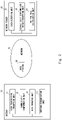
- Fig. 2 is a configuration diagram showing a communication system 100 according to a first example embodiment.
- the communication system 100 includes gateways 10 and a network server 20.
- the gateway 10 and the network server 20 are connected via a network 40.
- the gateway 10 includes a data transmission/reception unit 11, a connectivity confirmation unit 12, a data transfer unit 13, and a hopping communication unit 14.
- the data transmission/reception unit 11 receives data transmitted by devices and transmits the data to the network server 20 via the network 40. In this case, the data transmission/reception unit 11 performs protocol conversion on the data and transmits the data to a base station 30.
- the connectivity confirmation unit 12 confirms connectivity with another gateway and transmits a connectivity confirmation result to the network server 20.
- the connectivity confirmation result includes information about a transmission source gateway and a transmission destination gateway.
- the data transfer unit 13 transfers the data received from the device to another gateway 10 as transfer data.
- the data transfer unit 13 transfers the data when a failure occurs in communication with the base station 30.
- the hopping communication unit 14 transfers or discards the transfer data received from another gateway 10 to another gateway 10 based on a hopping rule or transmits the data to the network server 20 via the base station 30.
- the network server 20 includes a data reception unit 21, a connectivity confirmation result reception unit 22, and a hopping rule distribution unit 23.
- the data reception unit 21 receives the data transmitted by the gateway 10.
- the connectivity confirmation result reception unit 22 receives the connectivity confirmation results.
- the hopping rule distribution unit 23 creates a hopping rule based on the connectivity confirmation result.
- the hopping rule distribution unit 23 generates the hopping rule based on a criterion that a priority is given to communication from a gateway present with the range of a base station different from a base station the gateway camps on.
- the hopping rule distribution unit 23 distributes the hopping rule to the gateways 10.
- the data transferred from the gateway within the range of the base station same as the base station on which the gateway camps is discarded based on the hopping rule and is not transferred again.
- data can be transferred without causing data congestion.
- a communication system includes gateways 10 and a network server 20.
- a configuration diagram of the communication system is the same as that of Fig. 2 .
- a LoRa device transmits device data to the network server 20 via the gateway 10.
- the LoRa device communicates with the gateway 10 by LoRa radio.
- the LoRa device describes a hopping number in an unused area of a header of the device data.
- the hopping number is a predetermined value set by the network server 20.
- the gateway 10 includes a data transmission/reception unit 11, a connectivity confirmation unit 12, a data transfer unit 13, and a hopping communication unit 14.
- the data transmission/reception unit 11 receives device data from the LoRa device.
- the data transmission/reception unit 11 transmits the device data to the network server 20 via a base station on which the gateway 10 camps.
- the connectivity confirmation unit 12 periodically transmits connectivity confirmation data to gateways 10 other than the corresponding gateway 10, which may be hereinafter referred to as other gateways 10, by LoRa radio.
- the connectivity confirmation unit 12 receives the connectivity confirmation data transmitted by other gateways 10 and transmits the data to the network server 20.
- the data transfer unit 13 transfers the device data to other gateways 10 when the backhaul line becomes unavailable due to a failure or the like.
- the hopping communication unit 14 manages the hopping rule as a hopping database.
- the hopping rule defines processing for the data received from other gateways 10.
- Fig. 3 shows an example of the hopping database.
- Each record is composed of a GWID for identifying a transmission source gateway and processing for the device data transmitted from the gateway 10 corresponding to the GWID.
- the hopping communication unit 14 refers to the hopping database and the hopping number included in the header for the device data transferred from other gateways 10, and performs processing to transfer, discard or transmit the device data to the network server 20 through the backhaul line.
- Fig. 4 shows an example of communication by hopping.
- a gateway 10B transfers data from a LoRa device 50B to a gateway 10C.
- the gateway 10C transmits the data to the network server 20 via the base station 30B in accordance with a hopping rule. Other gateways discard the data in accordance with the hopping rule.
- the hopping communication unit 14 transfers the received device data only when the hopping number is other than 0.
- the hopping communication unit 14 performs processing for reducing the hopping number included in the header by one when transferring the device data.
- the hopping communication unit 14 discards the device data when the hopping number is 0.
- the network server 20 includes a data reception unit 21, a connectivity confirmation result reception unit 22, and a hopping rule distribution unit 23.
- the data reception unit 21 receives the device data transmitted by each LoRa device 50.
- the data reception unit 21 transmits the received data to a hgiher level application server according to the obtained device data.
- the connectivity confirmation result reception unit 22 receives the connectivity confirmation result from each gateway 10 and manages it as a connectivity confirmation database.
- the hopping rule distribution unit 23 refers to the connectivity confirmation database included in the connectivity confirmation result reception unit 22 to generate a hopping rule.
- the hopping rule distribution unit 23 distributes the generated hopping rule to each gateway 10.
- the hopping rule distribution unit 23 sets any hopping number for each LoRa device 50.
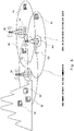
- Fig. 5 is a schematic diagram showing an arrangement example of each component.
- the LoRa device 50 is installed in a mountainous area.
- the LoRa device 50 transmits the device data to the network server 20.
- the gateway 10A is installed at a foot of a mountain, and the gateway 10B is installed in an urban area.
- the base station 30A is installed at a foot of the mountain, and the base station 30B is installed in the urban area.
- the base station 30A and the base station 30B are, for example, 3G/LTE base stations.
- the distance between the gateway 10A and the base station 30A is 0.5 km, and the gateway 10A camps on the base station 30A.
- the distance between the gateway 10B and the base station 30B is 0.5 km, and the gateway 10B camps on the base station 30B.
- the distance between the gateway 10A and the LoRa device 50 is 5 km, and the gateway 10A can receive the device data transmitted from the LoRa device 50.
- the distance between the gateway 10B and the LoRa device 50 is 10 km, and the gateway 10B cannot receive the device data transmitted from the LoRa device 50.
- the distance between the gateway 10A and the gateway 10B is 5 km, and the gateway 10A and the gateway 10B can communicate with each other by a LoRa radio method.
- the gateway 10A When a failure occurs in the backhaul line in the base station 30A installed at the foot of the mountain, the gateway 10A becomes unable to transmit the device data to the network server 20.
- the gateway 10A transfers the device data to the gateway 10B, and the gateway 10B transmits the device data to the network server 20.
- Fig. 5 shows a case in which the device data reaches only one gateway 10 installed at the foot of the mountain and does not reach the gateway 10 installed in the urban area due to a problem of a positional relationship between the LoRa device 50 and the gateways 10.
- the device data may be collected in a mountainous area in order to detect a landslide in the mountainous area.
- a radio wave reaching distance of the LoRa radio method is longer than that of the 3G/LTE radio method.
- a difference between the radio wave intensity of LoRa radio method and that of the 3G/LTE radio method is 20 dBm, and a difference between the radio wave reaching distance of the LoRa radio method and that of the 3G/LTE radio method is several hundred meters or more.
- a cell size of a carrier network such as 3G/LTE is generally several hundred meters to several kilometers.
- a cell of several kilometers is referred to as a large zone and a cell of several hundred meters is referred to a small zone.
- the large zone applies to plains with low population density, and the small zone applies to urban areas with high population density.
- cells in mountainous areas which are common in Japan, are often small zones due to geographical constraints. In mountainous areas, base stations are often installed halfway up a mountain. In such a case, a dead zone is generated at the top of the mountain, a ridge or a valley of the mountain.
- LoRa devices for sensing temperature, vibration, and the like are installed in a mountainous area to detect a landslide in the mountain.
- the gateways 10 for collecting data from the LoRa devices at the foot of the mountain since the location of the 3G/LTE base station is limited, it is often necessary to install the gateways 10 for collecting data from the LoRa devices at the foot of the mountain.
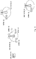
- Fig. 6 is a schematic diagram showing a case where the gateways 10 and the base stations 30 are installed at the foot of a mountain.
- the LoRa device 50 When environmental information or the like is collected in a mountainous area by utilizing the LoRa communication method, if a failure occurs in a backhaul line in a base station and communication becomes difficult, the LoRa device 50 cannot transmit the device data to the network server 20.
- the gateway 10 camping on the base station where the failure has occured transfers data to another gateway 10, and the device data can be transmitted to the network server 20 using the backhaul line of the base station on which the transfer destination gateway 10 camps.
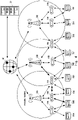
- a procedure for transmitting the device data to the network server 20 by hopping in the event of a failure in the backhaul line will be described with reference to Fig. 7 .
- Fig. 8 schematically shows an arrangement example of each component.
- a gateway 10A, a gateway 10B, and a gateway 10C camp on a base station 30A.
- a gateway 10D camps on a base station 30B.
- a gateway 10E camps on a base station 30C.
- the base station 30A is present at a foot of a mountain, and the base stations 30B and 30C are present in an urban area.
- the distance between the LoRa device 50 and the gateway 10A is about 5 km, and LoRa communication is possible between them.
- the distance between the LoRa device and the gateways 10D and 10E is more than 10 km, and LoRa communication is not possible between them.
- the distance between the gateway 10A and the gateway 10D is 5 km, and LoRa communication is possible between them.
- the distance between the gateway 10A and the gateway 10E is about 7 km, and LoRa communication is possible between them.
- the LoRa device 50 transmits device data to the gateway 10A.
- the gateway 10A transmits the device data to the network server 20 via the base station 30A.
- the gateway 10A When a failure occurs in the backhaul line of the base station 30A, the gateway 10A, which has received the device data, cannot transmit the data to the network server 20 unless hopping communication is performed.
- the gateway 10B and the gateway 10C camp only on the base station 30A. Therefore, even if data is transferred from the gateway 10A to the gateways 10B and 10C, the device data cannot be transmitted to the network server 20.
- the gateway 10D and the gateway 10E camp on the base stations 30B and 30C in operation, respectively.
- the gateway 10D and the gateway 10E can communicate with the gateway 10A.
- the device data can be transmitted from the gateway 10A to the network server 20 via the gateway 10D or the gateway 10E.
- the gateway 10A Because of the difference in the radio wave intensity, it is optimal for the gateway 10A to transfer the data via the gateway 10D and the base station 30B.
- Each gateway 10 transmits connectivity confirmation data including an identifier of a transmission source gateway every fixed time using a connectivity confirmation function.
- the gateway 10, which has received the connectivity confirmation data transmits a set of the transmission source gateway, the transfer destination gateway, and the radio wave intensity to the network server 20 as the connectivity confirmation result (S1).
- the transfer destination gateway is an identifier of the gateway 10 itself which has received the connectivity confirmation data.
- the network server 20 generates a set of the transmission source gateway, a transfer destination gateway, and whether or not transfer is possible (accept or discard) based on the connectivity confirmation result received in (S1), and records it in the connectivity confirmation database.
- the network server 20 determines whether or not transfer is possible according to the following rules (1) and (2) based on all connectivity confirmation results having the gateway 10 (gateway 10x) as a transmission source (S2).
- the gateway 10A transmits the connectivity confirmation data.
- the gateway 10B, the gateway 10C, the gateway 10D, and the gateway 10E receive the connectivity confirmation data.
- the radio wave intensity included in the connectivity confirmation result transmitted from the remaining gateway 10D is compared with the radio wave intensity included in the connectivity confirmation result transmitted from the gateway 10E, and the gateway 10D having higher radio wave intensity is selected as a transfer destination from the gateway 10A.
- a set of [transmission source: gateway 10A, transfer destination: gateway 10D, transfer: accept] and [transmission source: gateway 10A, transfer destination: gateway 10E, transfer: discard] is recorded in the connectivity confirmation database.
- the network server distributes the hopping rule to each gateway by the hopping rule distribution unit (S3).
- the hopping rule distribution unit refers to a transfer destination gateway 10y for each record of the connectivity confirmation database to transmit the corresponding record to the transfer destination gateway 10y.
- the gateway 10 writes the hopping rule received from the network server 20 in its own hopping database (S4).
- a rule of "discard data transferred from the gateway 10A" is written in the hopping databases held by the gateway 10B, the gateway 10C, and the gateway 10E, and a rule of "accept data transferred from the gateway 10A" is written in the hopping database of the gateway 10D.
- Each gateway 10 periodically confirms connectivity with a base station on which the gateway 10 camps, and turns on its hopping mode when a failure is detected (S5).
- the hopping mode indicates whether or not hopping communication is performed. When the hopping mode is on, the hopping communication is performed, while when the hopping mode is off, the hopping communication is not performed.
- the gateway When the gateway with its the hopping mode on receives the device data from the LoRa device 50, the gateway transfers the device data to other gateways 10 by a data transfer function (S6).
- the gateway 10 which has received the device data transferred from other gateways 10, refers to the hopping rule corresponding to the transmission source gateway and the hopping number of the device data to determine whether to accept or discard the device data.
- the hopping rule is recorded in the hopping database held by the gateway 10 itself.
- the received device data is transmitted to the network server 20 via the base station.
- the base station 30 on which the gateway 10 itself camps is unavailable when the device data is to be accepted, the device data is transferred again to another gateway 10 (S7).
- the gateway 10A receives the device data transmitted by the LoRa device 50. However, it is assumed that the device data has not reached the gateways 10B, 10C, 10D, and 10E due to the positional relationship with the LoRa device.
- the gateway 10A transfers the data received from the LoRa device to the other gateways 10 (S6).
- the gateways 10B, 10C, 10D, and 10E receive the transferred device data.
- the transfer from the gateway 10A is set as "discard". Therefore, the gateway 10B, the gateway 10C, and the gateway 10E discard the received device data (S7).
- the transfer from the gateway 10A is set as accept.
- the gateway 10D transmits the device data to the network server 20 via the backhaul line (S7).
- connectivity is confirmed among the gateways 10 in normal times, and the hopping rule is generated based on the connectivity confirmation result.
- the conditions for accepting or discarding data transfers between the gateways 10 are determined based on the hopping rule.
- each gateway 10 performs data transfer in accordance with the hopping rule.
- the present disclosure can also be applied when the communication traffic of SIM associated with the gateway reaches an upper limit and communication becomes unavailable.
Landscapes
- Engineering & Computer Science (AREA)
- Computer Networks & Wireless Communication (AREA)
- Signal Processing (AREA)
- Mobile Radio Communication Systems (AREA)
Abstract
Description
- The present disclosure relates to a communication system, a communication method, and a server, and to a hopping communication technique.
- IoT (Internet of things) networks using sensor devices for measuring temperature and humidity, etc. are required to consume little power and be capable of long-distance transmission. Sensing IoT requires a communication technology different from that of 3G/LTE.
- For example, the LoRaWAN (Long Range Wide Area Network) is one of networks for IoT and is an unlicensed band that does not require a license.
- LoRaWAN is a relatively new network, and some specifications of LoRaWAN not defined.
-
Fig. 1 is a configuration diagram showing a network architecture of LoRaWAN. The LoRaWAN network is composed of LoRa devices, LoRa gateways, LoRa network servers, and application servers. - The LoRa device transmits data to a LoRa gateway using the LoRa radio modulation method. The LoRa gateway converts the protocol from the LoRa wireless modulation method to TCP/IP and transmits data to the LoRa network server. The LoRa network server transmits the data to an appropriate application server.
- In the LoRaWAN, the communication at a level higher than the LoRa gateway uses a backhaul line such as 3G or LTE. Therefore, when congestion or a failure occurs in a base station, there is a problem that the LoRa device cannot communicate with the application server. In order to address this issue, it is necessary to prepare a mechanism that enables continuous collection of data from the LoRa devices even if the backhaul line using a carrier network such as 3G/LTE becomes unavailable.
-
Patent Literature 1 discloses a technique in which a radio communication terminal camping outside the base station transmits rescue information to a predetermined report destination via another radio communication terminal. By distributing a reporting completed list, the radio communication terminals can end the report. - Patent Literature 1:
Japanese Unexamined Patent Application Publication No. 2015-005915 - As described above, when a failure occurs in the backhaul line, there is a problem that the device cannot communicate with the application server.
- One of the solutions to this is to perform multi-hop communication by wireless communication. Here, for example, in LoRaWAN, since peer-to-peer communication like Wi-Fi is not defined, broadcast communication is performed instead of unicast communication. In such a case, since the gateway transmits data to all the gateways within the range where radio waves can reach, there may be congestion in the communication.
- The possibility of causing congestion in the communication is significantly high, because LoRaWAN is a network capable of long-distance transmission.
- It is said that LoRa communication of LPWA (LoW Power Wide Area) can receive radio waves from a distance of 10 km or more in an environment with good visibility. Therefore, the number of gateways in the range where radio waves of LoRa communication can reach from a certain gateway is much larger than that of existing networks, compared with those in which radio waves can reach from a short distance. This greatly increases the risk of causing congestion in the communication while communicating in multi-hop. Congestion, which requires little attention when existing wireless multi-hop communication is used, is a very important issue in LoRa, where radio waves travel over long distances.
- In the method disclosed in
Patent Literature 1, since it takes a certain time to prepare and distribute the reporting completed list, it is impossible to prevent congestion during this time. Further, the method described inPatent Literature 1 cannot handle the case where data is continuously transmitted by a sensor device. - The present disclosure has been made to solve the above problems and an object of the present disclosure is to provide a communication system, a communication method, and a server capable of hopping communication without causing congestion.
- A communication system according to the present disclosure includes: a plurality of gateways configured to receive device data transmitted from devices and transmit the device data to a network server via a network; and the network server configured to receive the device data transmitted from the gateways via the network. Each of the gateways includes: connectivity confirmation means for confirming connectivity with another gateway and transmitting a connectivity confirmation result to the network server; data transfer means for transferring the device data to an unspecified gateway as transfer data when a failure occurs in communication with a base station the corresponding gateway camps on; and hopping communication means for executing processing on the transfer data transferred from another gateway based on a hopping rule. The network server includes: connectivity confirmation result reception means for receiving the connectivity confirmation results from the gateways; and hopping rule distribution means for generating the hopping rule from the connectivity confirmation results based on a criterion for giving a priority to a transfer from the gateway camping on a base station different from the base station on which the corresponding gateway camps and then distributing the generated hoping rule to the gateways.
- A method of communication between gateways and a network server via a network according to the present disclosure includes: performing, by each gateway, connectivity confirmation with another gateway and transmitting a connectivity confirmation result to the network server; generating, by the network server, hopping rule for defining processing on transfer data in the gateways from the connectivity confirmation results based on a criterion for giving a priority to communication from the gateway camping on a base station different from a base station the corresponding gateway camps on and then distributing the hopping rule to the gateways; transferring, by each gateway, device data received from a device to an unspecified gateway as the transfer data when a failure occurs in communication with the base station the correspodning gateway camps on; and performing, by each gateway, processing on the transfer data transmitted from another gateway in accordance with the hopping rule.
- A server according to the present disclosure for generating hopping rule for a plurality of gateways receiving device data transmitted from devices and transmitting the device data to a network server via a network, the server includes: connectivity confirmation result reception means for receiving, from each gateway, a result of confirming connectivity with another gateway; and hopping rule distribution means for generating the hopping rule from the connectivity confirmation results based on a criterion for giving a priority to a transfer from the gateway camping on a base station different from a base station the corresponding gateway camps on and distributing the generated hopping rule to the gateways.
- According to the present disclosure, it is possible to provide a communication system, a communication method, and a server capable of hopping communication without causing congestion.
-
-
Fig. 1 is a configuration diagram showing a configuration of LoRaWAN; -
Fig. 2 is a configuration diagram showing a configuration of a wireless communication system according to an example embodiment for implementing a first disclosure; -
Fig. 3 shows an example of a hopping database according to an example embodiment for implementing a second disclosure; -
Fig. 4 shows an outline of an example of hopping communication according to the example embodiment for implementing the second disclosure; -
Fig. 5 is a schematic diagram showing an example arrangement of components according to the example embodiment for implementing the second disclosure; -
Fig. 6 is a schematic diagram showing an example of LoRa devices installed in a mountainous area according to the example embodiment for implementing the second disclosure; -
Fig. 7 shows an example arrangement of a communication system according to the example embodiment for implementing the second disclosure; -
Fig. 8 is a schematic diagram showing an example of a communication system according to the example embodiment for implementing the second disclosure; -
Fig. 9 is a flowchart showing an operation of the communication system according to the example embodiment for implementing the second disclosure; and -
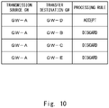
Fig. 10 shows an example of a connectivity confirmation database according to the example embodiment for implementing the second disclosure. -
Fig. 2 is a configuration diagram showing acommunication system 100 according to a first example embodiment. - The
communication system 100 includesgateways 10 and anetwork server 20. Thegateway 10 and thenetwork server 20 are connected via anetwork 40. - The
gateway 10 includes a data transmission/reception unit 11, aconnectivity confirmation unit 12, adata transfer unit 13, and ahopping communication unit 14. - The data transmission/
reception unit 11 receives data transmitted by devices and transmits the data to thenetwork server 20 via thenetwork 40. In this case, the data transmission/reception unit 11 performs protocol conversion on the data and transmits the data to abase station 30. - The
connectivity confirmation unit 12 confirms connectivity with another gateway and transmits a connectivity confirmation result to thenetwork server 20. The connectivity confirmation result includes information about a transmission source gateway and a transmission destination gateway. - The
data transfer unit 13 transfers the data received from the device to anothergateway 10 as transfer data. Thedata transfer unit 13 transfers the data when a failure occurs in communication with thebase station 30. - The hopping
communication unit 14 transfers or discards the transfer data received from anothergateway 10 to anothergateway 10 based on a hopping rule or transmits the data to thenetwork server 20 via thebase station 30. - The
network server 20 includes adata reception unit 21, a connectivity confirmationresult reception unit 22, and a hopping rule distribution unit 23. - The
data reception unit 21 receives the data transmitted by thegateway 10. - The connectivity confirmation
result reception unit 22 receives the connectivity confirmation results. - The hopping rule distribution unit 23 creates a hopping rule based on the connectivity confirmation result. The hopping rule distribution unit 23 generates the hopping rule based on a criterion that a priority is given to communication from a gateway present with the range of a base station different from a base station the gateway camps on. The hopping rule distribution unit 23 distributes the hopping rule to the
gateways 10. - In this case, the data transferred from the gateway within the range of the base station same as the base station on which the gateway camps is discarded based on the hopping rule and is not transferred again. Thus, data can be transferred without causing data congestion.
- A communication system according to this example embodiment includes
gateways 10 and anetwork server 20. A configuration diagram of the communication system is the same as that ofFig. 2 . - A LoRa device transmits device data to the
network server 20 via thegateway 10. The LoRa device communicates with thegateway 10 by LoRa radio. - The LoRa device describes a hopping number in an unused area of a header of the device data. The hopping number is a predetermined value set by the
network server 20. - The
gateway 10 includes a data transmission/reception unit 11, aconnectivity confirmation unit 12, adata transfer unit 13, and a hoppingcommunication unit 14. - The data transmission/
reception unit 11 receives device data from the LoRa device. The data transmission/reception unit 11 transmits the device data to thenetwork server 20 via a base station on which thegateway 10 camps. - The
connectivity confirmation unit 12 periodically transmits connectivity confirmation data togateways 10 other than the correspondinggateway 10, which may be hereinafter referred to asother gateways 10, by LoRa radio. Theconnectivity confirmation unit 12 receives the connectivity confirmation data transmitted byother gateways 10 and transmits the data to thenetwork server 20. - The
data transfer unit 13 transfers the device data toother gateways 10 when the backhaul line becomes unavailable due to a failure or the like. - The hopping
communication unit 14 manages the hopping rule as a hopping database. The hopping rule defines processing for the data received fromother gateways 10. -
Fig. 3 shows an example of the hopping database. Each record is composed of a GWID for identifying a transmission source gateway and processing for the device data transmitted from thegateway 10 corresponding to the GWID. - The hopping
communication unit 14 refers to the hopping database and the hopping number included in the header for the device data transferred fromother gateways 10, and performs processing to transfer, discard or transmit the device data to thenetwork server 20 through the backhaul line. -
Fig. 4 shows an example of communication by hopping. When a failure occurs in a base station A, agateway 10B transfers data from aLoRa device 50B to a gateway 10C. - The gateway 10C transmits the data to the
network server 20 via thebase station 30B in accordance with a hopping rule. Other gateways discard the data in accordance with the hopping rule. - The hopping
communication unit 14 transfers the received device data only when the hopping number is other than 0. The hoppingcommunication unit 14 performs processing for reducing the hopping number included in the header by one when transferring the device data. The hoppingcommunication unit 14 discards the device data when the hopping number is 0. By setting the hopping number and performing the above operation, it is possible to limit the number of transfer of the device data to a predetermined value and prevent the repetition of the retransfer. For example, by setting the hopping number to 1, the transfer of the device data can be limited to a maximum of one stage. - The
network server 20 includes adata reception unit 21, a connectivity confirmationresult reception unit 22, and a hopping rule distribution unit 23. - The
data reception unit 21 receives the device data transmitted by eachLoRa device 50. Thedata reception unit 21 transmits the received data to a hgiher level application server according to the obtained device data. - The connectivity confirmation
result reception unit 22 receives the connectivity confirmation result from eachgateway 10 and manages it as a connectivity confirmation database. - The hopping rule distribution unit 23 refers to the connectivity confirmation database included in the connectivity confirmation
result reception unit 22 to generate a hopping rule. The hopping rule distribution unit 23 distributes the generated hopping rule to eachgateway 10. - The hopping rule distribution unit 23 sets any hopping number for each
LoRa device 50. - An outline of this example embodiment will be described with reference to
Fig. 5. Fig. 5 is a schematic diagram showing an arrangement example of each component. - The
LoRa device 50 is installed in a mountainous area. TheLoRa device 50 transmits the device data to thenetwork server 20. - The
gateway 10A is installed at a foot of a mountain, and thegateway 10B is installed in an urban area. Thebase station 30A is installed at a foot of the mountain, and thebase station 30B is installed in the urban area. Thebase station 30A and thebase station 30B are, for example, 3G/LTE base stations. - The distance between the
gateway 10A and thebase station 30A is 0.5 km, and thegateway 10A camps on thebase station 30A. The distance between thegateway 10B and thebase station 30B is 0.5 km, and thegateway 10B camps on thebase station 30B. - The distance between the
gateway 10A and theLoRa device 50 is 5 km, and thegateway 10A can receive the device data transmitted from theLoRa device 50. The distance between thegateway 10B and theLoRa device 50 is 10 km, and thegateway 10B cannot receive the device data transmitted from theLoRa device 50. - The distance between the
gateway 10A and thegateway 10B is 5 km, and thegateway 10A and thegateway 10B can communicate with each other by a LoRa radio method. - When a failure occurs in the backhaul line in the
base station 30A installed at the foot of the mountain, thegateway 10A becomes unable to transmit the device data to thenetwork server 20. - In such a case, in the example embodiment of the present disclosure, the
gateway 10A transfers the device data to thegateway 10B, and thegateway 10B transmits the device data to thenetwork server 20. -
Fig. 5 shows a case in which the device data reaches only onegateway 10 installed at the foot of the mountain and does not reach thegateway 10 installed in the urban area due to a problem of a positional relationship between theLoRa device 50 and thegateways 10. In such a case, it is assumed that the present disclosure is particularly effective. As a specific example, the device data may be collected in a mountainous area in order to detect a landslide in the mountainous area. - When conditions such as an antenna height, an antenna length, and a radio wave output are the same, a radio wave reaching distance of the LoRa radio method is longer than that of the 3G/LTE radio method. In urban areas, it is considered that a difference between the radio wave intensity of LoRa radio method and that of the 3G/LTE radio method is 20 dBm, and a difference between the radio wave reaching distance of the LoRa radio method and that of the 3G/LTE radio method is several hundred meters or more.
- On the other hand, a cell size of a carrier network such as 3G/LTE is generally several hundred meters to several kilometers. A cell of several kilometers is referred to as a large zone and a cell of several hundred meters is referred to a small zone. The large zone applies to plains with low population density, and the small zone applies to urban areas with high population density. On the other hand, cells in mountainous areas, which are common in Japan, are often small zones due to geographical constraints. In mountainous areas, base stations are often installed halfway up a mountain. In such a case, a dead zone is generated at the top of the mountain, a ridge or a valley of the mountain.
- LoRa devices for sensing temperature, vibration, and the like are installed in a mountainous area to detect a landslide in the mountain. In this case, since the location of the 3G/LTE base station is limited, it is often necessary to install the
gateways 10 for collecting data from the LoRa devices at the foot of the mountain. -
Fig. 6 is a schematic diagram showing a case where thegateways 10 and thebase stations 30 are installed at the foot of a mountain. - When environmental information or the like is collected in a mountainous area by utilizing the LoRa communication method, if a failure occurs in a backhaul line in a base station and communication becomes difficult, the
LoRa device 50 cannot transmit the device data to thenetwork server 20. - According to the example embodiment of the present disclosure, even if a failure occurs in the backhaul line in the
base station 30 installed at the foot or halfway up the mountain, thegateway 10 camping on the base station where the failure has occured transfers data to anothergateway 10, and the device data can be transmitted to thenetwork server 20 using the backhaul line of the base station on which thetransfer destination gateway 10 camps. - A procedure for transmitting the device data to the
network server 20 by hopping in the event of a failure in the backhaul line will be described with reference toFig. 7 . -
Fig. 8 schematically shows an arrangement example of each component. - A
gateway 10A, agateway 10B, and a gateway 10C camp on abase station 30A. Agateway 10D camps on abase station 30B. Agateway 10E camps on abase station 30C. - It may be assumed that the
base station 30A is present at a foot of a mountain, and thebase stations - The distance between the
LoRa device 50 and thegateway 10A is about 5 km, and LoRa communication is possible between them. The distance between the LoRa device and thegateways - The distance between the
gateway 10A and thegateway 10D is 5 km, and LoRa communication is possible between them. The distance between thegateway 10A and thegateway 10E is about 7 km, and LoRa communication is possible between them. When thegateway 10A transmits data by the LoRa communication method, the radio wave intensity received by thegateway 10D is larger than the radio wave intensity received by thegateway 10E. - During normal operations, the
LoRa device 50 transmits device data to thegateway 10A. Thegateway 10A transmits the device data to thenetwork server 20 via thebase station 30A. - When a failure occurs in the backhaul line of the
base station 30A, thegateway 10A, which has received the device data, cannot transmit the data to thenetwork server 20 unless hopping communication is performed. - The
gateway 10B and the gateway 10C camp only on thebase station 30A. Therefore, even if data is transferred from thegateway 10A to thegateways 10B and 10C, the device data cannot be transmitted to thenetwork server 20. - The
gateway 10D and thegateway 10E camp on thebase stations gateway 10D and thegateway 10E can communicate with thegateway 10A. Thus, the device data can be transmitted from thegateway 10A to thenetwork server 20 via thegateway 10D or thegateway 10E. - Because of the difference in the radio wave intensity, it is optimal for the
gateway 10A to transfer the data via thegateway 10D and thebase station 30B. - An operation before a failure occurs in the backhaul line will be described with reference to
Fig. 9 . - Each
gateway 10 transmits connectivity confirmation data including an identifier of a transmission source gateway every fixed time using a connectivity confirmation function. Thegateway 10, which has received the connectivity confirmation data, transmits a set of the transmission source gateway, the transfer destination gateway, and the radio wave intensity to thenetwork server 20 as the connectivity confirmation result (S1). Here, the transfer destination gateway is an identifier of thegateway 10 itself which has received the connectivity confirmation data. - The
network server 20 generates a set of the transmission source gateway, a transfer destination gateway, and whether or not transfer is possible (accept or discard) based on the connectivity confirmation result received in (S1), and records it in the connectivity confirmation database. - The
network server 20 determines whether or not transfer is possible according to the following rules (1) and (2) based on all connectivity confirmation results having the gateway 10 (gateway 10x) as a transmission source (S2). - (1) The
network server 20 classifies the transfer to thegateway 10 into "discard" based on the connectivity confirmation result having thegateway 10 camping on the same base station as the base station on which the gateway 10x camps as a transfer destination. That is, no transfer is performed from the gateway 10x to thegateway 10. - (2) The
network server 20 classifies the transfer to thegateway 10 having the highest radio wave intensity included in the connectivity confirmation result into "accept" for the connectivity confirmation results having thegateway 10 other than thegateway 10 classified into "discard" in (1) as the transfer destination. That is, the transfer is performed from the gateway 10x to thegateway 10. The transfer to thegateway 10 other than thegateway 10 classified as "accept" is classified as "discard". - A specific example of judging whether or not transfer is possible in the case of
Fig. 7 will be described. - The
gateway 10A transmits the connectivity confirmation data. Thegateway 10B, the gateway 10C, thegateway 10D, and thegateway 10E receive the connectivity confirmation data. - First, since the
gateway 10B and the gateway 10C camp on the same base station as the base station on which thegateway 10A camp, [transmission source:gateway 10A, transfer destination:gateway 10B, transfer: discard] and [transmission source:gateway 10A, transfer destination: gateway 10C, transfer: discard] are recorded in the connectivity confirmation database. - Next, the radio wave intensity included in the connectivity confirmation result transmitted from the remaining
gateway 10D is compared with the radio wave intensity included in the connectivity confirmation result transmitted from thegateway 10E, and thegateway 10D having higher radio wave intensity is selected as a transfer destination from thegateway 10A. As a result, a set of [transmission source:gateway 10A, transfer destination:gateway 10D, transfer: accept] and [transmission source:gateway 10A, transfer destination:gateway 10E, transfer: discard] is recorded in the connectivity confirmation database. - Consequently, the connectivity confirmation database shown in
Fig. 10 is generated. - The network server distributes the hopping rule to each gateway by the hopping rule distribution unit (S3). The hopping rule distribution unit refers to a transfer destination gateway 10y for each record of the connectivity confirmation database to transmit the corresponding record to the transfer destination gateway 10y.
- The
gateway 10 writes the hopping rule received from thenetwork server 20 in its own hopping database (S4). - In the cases shown in
Figs. 7 and10 , a rule of "discard data transferred from thegateway 10A" is written in the hopping databases held by thegateway 10B, the gateway 10C, and thegateway 10E, and a rule of "accept data transferred from thegateway 10A" is written in the hopping database of thegateway 10D. - An operation when a failure occurs in the backhaul line will be described with reference to
Fig. 9 . - When a failure occurs in the backhaul line, data is transferred from the LoRa device to the
network server 20 via the plurality ofgateways 10 according to the following procedure. - Each
gateway 10 periodically confirms connectivity with a base station on which thegateway 10 camps, and turns on its hopping mode when a failure is detected (S5). The hopping mode indicates whether or not hopping communication is performed. When the hopping mode is on, the hopping communication is performed, while when the hopping mode is off, the hopping communication is not performed. - When the gateway with its the hopping mode on receives the device data from the
LoRa device 50, the gateway transfers the device data toother gateways 10 by a data transfer function (S6). - The
gateway 10, which has received the device data transferred fromother gateways 10, refers to the hopping rule corresponding to the transmission source gateway and the hopping number of the device data to determine whether to accept or discard the device data. The hopping rule is recorded in the hopping database held by thegateway 10 itself. - If the base station on which the
gateway 10 itself camps is available when the device data is to be accepted, the received device data is transmitted to thenetwork server 20 via the base station. On the other hand, if thebase station 30 on which thegateway 10 itself camps is unavailable when the device data is to be accepted, the device data is transferred again to another gateway 10 (S7). - As a specific example, an operation when a failure occurs in the backhaul line in the
base station 30A shown inFig. 7 will be described. - The
gateway 10A receives the device data transmitted by theLoRa device 50. However, it is assumed that the device data has not reached thegateways - When the hopping mode of the
gateway 10A is on, thegateway 10A transfers the data received from the LoRa device to the other gateways 10 (S6). Thegateways - In the hopping rule included in the
gateway 10B, the gateway 10C, and thegateway 10E, the transfer from thegateway 10A is set as "discard". Therefore, thegateway 10B, the gateway 10C, and thegateway 10E discard the received device data (S7). - In the hopping rule provided in the
gateway 10D, the transfer from thegateway 10A is set as accept. When no failure is occuring in thebase station 30B, thegateway 10D transmits the device data to thenetwork server 20 via the backhaul line (S7). - In the example embodiment of the present disclosure, connectivity is confirmed among the
gateways 10 in normal times, and the hopping rule is generated based on the connectivity confirmation result. The conditions for accepting or discarding data transfers between thegateways 10 are determined based on the hopping rule. When a failure occurs in the backhaul line, eachgateway 10 performs data transfer in accordance with the hopping rule. - It is thus possible to continuously collect data from the LoRa device in the event of a failure in the backhaul line without causing congestion in communication due to repeated broadcasts.
- In addition to the occurrence of a failure in the backhaul line, the present disclosure can also be applied when the communication traffic of SIM associated with the gateway reaches an upper limit and communication becomes unavailable.
- In the above description, an example in which the device and the gateway perform LoRa communication is shown, but the present disclosure is not limited to this and other communication methods may be used.
- Although the present disclosure has been described with reference to the example embodiments, the present disclosure is not limited to the above. The configurations and details of the present disclosure may be modified in various ways that could be understood by those skilled in the art within the scope of the disclosure.
- This application claims priority on the basis of
Japanese Patent Application No. 2019-095048, filed May 21, 2019 - Reference Signs List
- 10, 10A, 10B, 10C, 10D, 10E, 10x, 10y
- GATEWAY
- 11
- DATA TRANSMISSION/RECEPTION UNIT
- 12
- CONNECTIVITY CONFIRMATION UNIT
- 13
- DATA TRANSFER UNIT
- 14
- HOPPING COMMUNICATION UNIT
- 20
- NETWORK SERVER
- 21
- DATA RECEPTION UNIT
- 22
- CONNECTIVITY CONFIRMATION RECEPTION UNIT
- 23
- HOPPING RULE DISTRIBUTION UNIT
- 30, 30A, 30B, 30C
- BASE STATION
- 40
- NETWORK
- 50, 50A, 50B
- LoRa DEVICE
- 100
- COMMUNICATION SYSTEM
Claims (10)
- A communication system comprising:a plurality of gateways configured to receive device data transmitted from devices and transmit the device data to a network server via a network; andthe network server configured to receive the device data transmitted from the gateways via the network, whereineach of the gateways comprises:connectivity confirmation means for confirming connectivity with another gateway and transmitting a connectivity confirmation result to the network server;data transfer means for transferring the device data to an unspecified gateway as transfer data when a failure occurs in communication with a base station the corresponding gateway camps on; andhopping communication means for executing processing on the transfer data transferred from another gateway based on a hopping rule,the network server comprises:connectivity confirmation result reception means for receiving the connectivity confirmation results from the gateways; andhopping rule distribution means for generating the hopping rule from the connectivity confirmation results based on a criterion for giving a priority to a transfer from the gateway camping on a base station different from the base station on which the corresponding gateway camps and then distributing the generated hoping rule to the gateways.
- The communication system according to Claim 1, wherein
the hopping rule distribution means generates the hopping rule from the connectivity confirmation results based on a criterion for giving a priority to communication from the gateway camping on the base station different from the base station on which the corresponding gateway camps and including highest received radio wave intensity and then distributes the hopping rule to the gateways. - The communication system according to Claim 1 or 2, wherein
the connectivity confirmation result includes information about a transmission source, a transmission destination, and radio wave intensity. - The communication system according to any one of Claims 1 to 3, wherein
the hopping communication means performs processing of discarding the transfer data or transmitting the transfer data to the base station based on the hopping rule and a hopping number described in a header of the device data. - The communication system according to any one of Claims 1 to 4, wherein
the gateway communicates with the device by a LoRa method; - The communication system according to any one of Claims 1 to 5, wherein
the data transfer means transfers the device data by the LoRa method. - A method of communication between gateways and a network server via a network, the method comprising:performing, by each gateway, connectivity confirmation with another gateway and transmitting a connectivity confirmation result to the network server;generating, by the network server, hopping rule for defining processing on transfer data in the gateways from the connectivity confirmation results based on a criterion for giving a priority to communication from the gateway camping on a base station different from a base station the corresponding gateway camps on and then distributing the hopping rule to the gateways;transferring, by each gateway, device data received from a device to an unspecified gateway as the transfer data when a failure occurs in communication with the base station the corresponding gateway camps on; andperforming, by each gateway, processing on the transfer data transmitted from another gateway in accordance with the hopping rule.
- The method according to Claim 7, wherein
the network server generates the hopping rule based on a criterion for giving a priority to communication from the gateway camping on the base station different from the base station the corresponding gateway camps on and including highest received radio wave intensity. - A server for generating hopping rule for a plurality of gateways receiving device data transmitted from devices and transmitting the device data to a network server via a network, the server comprising:connectivity confirmation result reception means for receiving, from each gateway, a result of confirming connectivity with another gateway; andhopping rule distribution means for generating the hopping rule from the connectivity confirmation results based on a criterion for giving a priority to a transfer from the gateway camping on a base station different from a base station the corresponding gateway camps on and distributing the generated hopping rule to the gateways.
- The server according to Claim 9, wherein
the hopping rule distribution means generates the hopping rule based on a criterion for giving a priority to communication from the gateway camping on the base station different from the base station the corresponding gateway camps on and including highest received radio wave intensity.
Applications Claiming Priority (2)
| Application Number | Priority Date | Filing Date | Title |
|---|---|---|---|
| JP2019095048 | 2019-05-21 | ||
| PCT/JP2020/010247 WO2020235182A1 (en) | 2019-05-21 | 2020-03-10 | Communication system, communication method, and server |
Publications (2)
| Publication Number | Publication Date |
|---|---|
| EP3975607A1 true EP3975607A1 (en) | 2022-03-30 |
| EP3975607A4 EP3975607A4 (en) | 2022-07-13 |
Family
ID=73458773
Family Applications (1)
| Application Number | Title | Priority Date | Filing Date |
|---|---|---|---|
| EP20810026.3A Withdrawn EP3975607A4 (en) | 2019-05-21 | 2020-03-10 | Communication system, communication method, and server |
Country Status (4)
| Country | Link |
|---|---|
| US (1) | US12047861B2 (en) |
| EP (1) | EP3975607A4 (en) |
| JP (1) | JP7120456B2 (en) |
| WO (1) | WO2020235182A1 (en) |
Families Citing this family (4)
| Publication number | Priority date | Publication date | Assignee | Title |
|---|---|---|---|---|
| US12047861B2 (en) * | 2019-05-21 | 2024-07-23 | Nec Corporation | Communication system, communication method, and server |
| US20220210854A1 (en) * | 2020-12-30 | 2022-06-30 | Google Llc | Fixed Broadband Wireless Access CPE with Embedded IoT Gateways |
| CN112637370B (en) * | 2021-03-10 | 2021-06-18 | 武汉慧联无限科技有限公司 | Data processing method, device, equipment and storage medium |
| CN112769873B (en) * | 2021-04-07 | 2021-07-27 | 武汉慧联无限科技有限公司 | Data processing method and device, Internet of things platform and storage medium |
Family Cites Families (23)
| Publication number | Priority date | Publication date | Assignee | Title |
|---|---|---|---|---|
| US7647387B2 (en) * | 2000-12-01 | 2010-01-12 | Oracle International Corporation | Methods and systems for rule-based distributed and personlized content delivery |
| US8001052B2 (en) * | 2001-12-10 | 2011-08-16 | Dunkeld Bryan C | System and method for unique digital asset identification and transaction management |
| FR2840703B1 (en) * | 2002-06-06 | 2004-12-17 | Cit Alcatel | APPLICATION OF ACTIVE NETWORKS FOR LOAD DISTRIBUTION WITHIN A PLURALITY OF SERVICE SERVERS |
| EP1518353A2 (en) * | 2002-06-26 | 2005-03-30 | Siemens Aktiengesellschaft | Adaptive control of a network element |
| JP4418154B2 (en) * | 2002-12-27 | 2010-02-17 | 株式会社エヌ・ティ・ティ・ドコモ | Structured document conversion apparatus, structured document conversion method, and structured document conversion program |
| US7454489B2 (en) * | 2003-07-01 | 2008-11-18 | International Business Machines Corporation | System and method for accessing clusters of servers from the internet network |
| US9998802B2 (en) * | 2004-06-07 | 2018-06-12 | Sling Media LLC | Systems and methods for creating variable length clips from a media stream |
| US8468589B2 (en) * | 2006-01-13 | 2013-06-18 | Fortinet, Inc. | Computerized system and method for advanced network content processing |
| US20070140536A1 (en) * | 2005-12-19 | 2007-06-21 | Eastman Kodak Company | Medical image processing method and apparatus |
| CN104756079A (en) * | 2012-10-23 | 2015-07-01 | 日本电气株式会社 | Rule distribution server, as well as event processing system, method, and program |
| EP2948873A4 (en) * | 2013-01-28 | 2016-11-02 | Sanderling Man Ltd | DISTRIBUTION RULES AND DYNAMIC ADVERTISING PRESENTATION MANAGEMENT |
| JP5329727B1 (en) | 2013-02-19 | 2013-10-30 | ソフトバンクモバイル株式会社 | Communications system |
| JP2015005915A (en) | 2013-06-21 | 2015-01-08 | 株式会社ナカヨ | Report method, radio communication terminal, and program |
| CN104639451B (en) * | 2013-11-14 | 2019-03-22 | 中兴通讯股份有限公司 | Data flow splitting method and controller |
| FR3023663B1 (en) * | 2014-07-11 | 2016-08-05 | Sagemcom Broadband Sas | RESIDENTIAL GATEWAY RELAY BETWEEN A TERMINAL DEVICE AND A SERVER |
| US10108683B2 (en) * | 2015-04-24 | 2018-10-23 | International Business Machines Corporation | Distributed balanced optimization for an extract, transform, and load (ETL) job |
| EP3276992B1 (en) * | 2016-07-29 | 2018-12-12 | Deutsche Telekom AG | Control server in a communication network |
| US10417102B2 (en) * | 2016-09-30 | 2019-09-17 | Commvault Systems, Inc. | Heartbeat monitoring of virtual machines for initiating failover operations in a data storage management system, including virtual machine distribution logic |
| JP6654708B2 (en) | 2016-11-09 | 2020-02-26 | 株式会社日立製作所 | System, control device, and control method for controlling mobile device |
| US20180287869A1 (en) * | 2017-03-29 | 2018-10-04 | Intel Corporation | Technologies for altering modem configurations |
| US11134543B2 (en) * | 2017-03-31 | 2021-09-28 | Convida Wireless, Llc | Interworking LPWAN end nodes in mobile operator network |
| JP7120829B2 (en) | 2017-11-17 | 2022-08-17 | 積水化学工業株式会社 | How to connect multi-layer pipes |
| US12047861B2 (en) * | 2019-05-21 | 2024-07-23 | Nec Corporation | Communication system, communication method, and server |
-
2020
- 2020-03-10 US US17/610,226 patent/US12047861B2/en active Active
- 2020-03-10 WO PCT/JP2020/010247 patent/WO2020235182A1/en not_active Ceased
- 2020-03-10 JP JP2021520062A patent/JP7120456B2/en active Active
- 2020-03-10 EP EP20810026.3A patent/EP3975607A4/en not_active Withdrawn
Also Published As
| Publication number | Publication date |
|---|---|
| EP3975607A4 (en) | 2022-07-13 |
| WO2020235182A1 (en) | 2020-11-26 |
| JPWO2020235182A1 (en) | 2021-11-18 |
| JP7120456B2 (en) | 2022-08-17 |
| US12047861B2 (en) | 2024-07-23 |
| US20220248299A1 (en) | 2022-08-04 |
Similar Documents
| Publication | Publication Date | Title |
|---|---|---|
| US12047861B2 (en) | Communication system, communication method, and server | |
| Zhao et al. | Extending drive-thru data access by vehicle-to-vehicle relay | |
| US10091760B2 (en) | Method and apparatus for transmitting paging for V2X communication in wireless communication system | |
| US20190260464A1 (en) | Satellite and terrestrial load balancing | |
| EP1727317A1 (en) | Radio communication device and route search method | |
| EA009721B1 (en) | Data transport protocol for a multi-station network | |
| US20030003934A1 (en) | Method for enhancing mobility in a wireless mesh network | |
| US10826851B2 (en) | Method and system for routing delay-tolerant communication messages to a destination device | |
| US10375748B2 (en) | Method for terminal-to-terminal communication in a cellular mobile radio network, and a system therefor | |
| US20130250783A1 (en) | Systems and methods registration and maintenance of wireless clients via a proxy wireless network service | |
| US20150050954A1 (en) | Terminal device, mobile management device, communication system, and communication method | |
| US20220104030A1 (en) | Low latency hybrid network for battery powered endpoint communications | |
| EP2811785A1 (en) | Dynamic routing method in ad-hoc network and network device therefor | |
| US10959154B2 (en) | Low latency hybrid network for battery powered endpoint communications | |
| CN108882307B (en) | Method and device for separating control from service | |
| CN101945495B (en) | Difference frequency subnetwork communication system and method | |
| JP2001128231A (en) | Variable area ad hoc network | |
| KR101049940B1 (en) | How to send messages and how to send multihop messages in ubiquitous traffic sensor networks | |
| US8355366B2 (en) | Wireless communications node used in AD HOC network and method thereof | |
| CN107105475A (en) | A kind of wireless backhaul network access control method and device | |
| CN110089168B (en) | A paging method and device | |
| CN105049356A (en) | Data multi-hop routing acquisition method based on quality of service in monitoring network | |
| JP6989577B2 (en) | Communication system, information processing device, wireless terminal, information processing device control method, wireless terminal control method, and program | |
| Fedullo et al. | Exploiting hybrid medium access control and relaying strategies to overcome duty-cycle limitations in LoRa-based sensor networks | |
| CN116667883A (en) | A data transmission method, device and storage medium |
Legal Events
| Date | Code | Title | Description |
|---|---|---|---|
| STAA | Information on the status of an ep patent application or granted ep patent |
Free format text: STATUS: THE INTERNATIONAL PUBLICATION HAS BEEN MADE |
|
| PUAI | Public reference made under article 153(3) epc to a published international application that has entered the european phase |
Free format text: ORIGINAL CODE: 0009012 |
|
| STAA | Information on the status of an ep patent application or granted ep patent |
Free format text: STATUS: REQUEST FOR EXAMINATION WAS MADE |
|
| 17P | Request for examination filed |
Effective date: 20211119 |
|
| AK | Designated contracting states |
Kind code of ref document: A1 Designated state(s): AL AT BE BG CH CY CZ DE DK EE ES FI FR GB GR HR HU IE IS IT LI LT LU LV MC MK MT NL NO PL PT RO RS SE SI SK SM TR |
|
| A4 | Supplementary search report drawn up and despatched |
Effective date: 20220610 |
|
| RIC1 | Information provided on ipc code assigned before grant |
Ipc: H04W 40/22 20090101ALI20220603BHEP Ipc: H04W 40/12 20090101ALI20220603BHEP Ipc: H04W 24/04 20090101AFI20220603BHEP |
|
| DAV | Request for validation of the european patent (deleted) | ||
| DAX | Request for extension of the european patent (deleted) | ||
| STAA | Information on the status of an ep patent application or granted ep patent |
Free format text: STATUS: THE APPLICATION IS DEEMED TO BE WITHDRAWN |
|
| 18D | Application deemed to be withdrawn |
Effective date: 20230110 |