EP3975540A1 - Image sensor - Google Patents
Image sensor Download PDFInfo
- Publication number
- EP3975540A1 EP3975540A1 EP20844311.9A EP20844311A EP3975540A1 EP 3975540 A1 EP3975540 A1 EP 3975540A1 EP 20844311 A EP20844311 A EP 20844311A EP 3975540 A1 EP3975540 A1 EP 3975540A1
- Authority
- EP
- European Patent Office
- Prior art keywords
- liquid lens
- refractive power
- temperature
- application voltage
- property information
- Prior art date
- Legal status (The legal status is an assumption and is not a legal conclusion. Google has not performed a legal analysis and makes no representation as to the accuracy of the status listed.)
- Pending
Links
- 239000007788 liquid Substances 0.000 claims abstract description 118
- 238000003384 imaging method Methods 0.000 claims abstract description 32
- 230000003287 optical effect Effects 0.000 claims abstract description 24
- 238000012545 processing Methods 0.000 claims description 14
- 238000007689 inspection Methods 0.000 description 43
- 238000000034 method Methods 0.000 description 43
- 230000008569 process Effects 0.000 description 42
- 230000004044 response Effects 0.000 description 17
- 238000010191 image analysis Methods 0.000 description 8
- 230000008859 change Effects 0.000 description 5
- 238000012937 correction Methods 0.000 description 4
- 238000010586 diagram Methods 0.000 description 4
- 230000001276 controlling effect Effects 0.000 description 3
- 230000000875 corresponding effect Effects 0.000 description 3
- 230000006870 function Effects 0.000 description 2
- 238000009434 installation Methods 0.000 description 2
- 238000004886 process control Methods 0.000 description 2
- 230000001131 transforming effect Effects 0.000 description 2
- XLYOFNOQVPJJNP-UHFFFAOYSA-N water Substances O XLYOFNOQVPJJNP-UHFFFAOYSA-N 0.000 description 2
- 238000004458 analytical method Methods 0.000 description 1
- 230000000295 complement effect Effects 0.000 description 1
- 230000002596 correlated effect Effects 0.000 description 1
- 230000001419 dependent effect Effects 0.000 description 1
- 230000000694 effects Effects 0.000 description 1
- 230000005611 electricity Effects 0.000 description 1
- 238000010438 heat treatment Methods 0.000 description 1
- 238000005259 measurement Methods 0.000 description 1
- 238000012986 modification Methods 0.000 description 1
- 230000004048 modification Effects 0.000 description 1
- 230000002093 peripheral effect Effects 0.000 description 1
- 230000000630 rising effect Effects 0.000 description 1
- 229920006395 saturated elastomer Polymers 0.000 description 1
- 239000004065 semiconductor Substances 0.000 description 1
- 239000007787 solid Substances 0.000 description 1
- 238000011179 visual inspection Methods 0.000 description 1
Images




Classifications
-
- H—ELECTRICITY
- H04—ELECTRIC COMMUNICATION TECHNIQUE
- H04N—PICTORIAL COMMUNICATION, e.g. TELEVISION
- H04N23/00—Cameras or camera modules comprising electronic image sensors; Control thereof
- H04N23/50—Constructional details
- H04N23/52—Elements optimising image sensor operation, e.g. for electromagnetic interference [EMI] protection or temperature control by heat transfer or cooling elements
-
- G—PHYSICS
- G02—OPTICS
- G02B—OPTICAL ELEMENTS, SYSTEMS OR APPARATUS
- G02B26/00—Optical devices or arrangements for the control of light using movable or deformable optical elements
- G02B26/004—Optical devices or arrangements for the control of light using movable or deformable optical elements based on a displacement or a deformation of a fluid
- G02B26/005—Optical devices or arrangements for the control of light using movable or deformable optical elements based on a displacement or a deformation of a fluid based on electrowetting
-
- G—PHYSICS
- G02—OPTICS
- G02B—OPTICAL ELEMENTS, SYSTEMS OR APPARATUS
- G02B26/00—Optical devices or arrangements for the control of light using movable or deformable optical elements
- G02B26/004—Optical devices or arrangements for the control of light using movable or deformable optical elements based on a displacement or a deformation of a fluid
-
- G—PHYSICS
- G02—OPTICS
- G02B—OPTICAL ELEMENTS, SYSTEMS OR APPARATUS
- G02B3/00—Simple or compound lenses
- G02B3/12—Fluid-filled or evacuated lenses
- G02B3/14—Fluid-filled or evacuated lenses of variable focal length
-
- G—PHYSICS
- G02—OPTICS
- G02B—OPTICAL ELEMENTS, SYSTEMS OR APPARATUS
- G02B7/00—Mountings, adjusting means, or light-tight connections, for optical elements
- G02B7/02—Mountings, adjusting means, or light-tight connections, for optical elements for lenses
- G02B7/028—Mountings, adjusting means, or light-tight connections, for optical elements for lenses with means for compensating for changes in temperature or for controlling the temperature; thermal stabilisation
-
- G—PHYSICS
- G02—OPTICS
- G02F—OPTICAL DEVICES OR ARRANGEMENTS FOR THE CONTROL OF LIGHT BY MODIFICATION OF THE OPTICAL PROPERTIES OF THE MEDIA OF THE ELEMENTS INVOLVED THEREIN; NON-LINEAR OPTICS; FREQUENCY-CHANGING OF LIGHT; OPTICAL LOGIC ELEMENTS; OPTICAL ANALOGUE/DIGITAL CONVERTERS
- G02F1/00—Devices or arrangements for the control of the intensity, colour, phase, polarisation or direction of light arriving from an independent light source, e.g. switching, gating or modulating; Non-linear optics
- G02F1/29—Devices or arrangements for the control of the intensity, colour, phase, polarisation or direction of light arriving from an independent light source, e.g. switching, gating or modulating; Non-linear optics for the control of the position or the direction of light beams, i.e. deflection
-
- H—ELECTRICITY
- H04—ELECTRIC COMMUNICATION TECHNIQUE
- H04N—PICTORIAL COMMUNICATION, e.g. TELEVISION
- H04N23/00—Cameras or camera modules comprising electronic image sensors; Control thereof
- H04N23/50—Constructional details
- H04N23/55—Optical parts specially adapted for electronic image sensors; Mounting thereof
-
- H—ELECTRICITY
- H04—ELECTRIC COMMUNICATION TECHNIQUE
- H04N—PICTORIAL COMMUNICATION, e.g. TELEVISION
- H04N23/00—Cameras or camera modules comprising electronic image sensors; Control thereof
- H04N23/57—Mechanical or electrical details of cameras or camera modules specially adapted for being embedded in other devices
-
- H—ELECTRICITY
- H04—ELECTRIC COMMUNICATION TECHNIQUE
- H04N—PICTORIAL COMMUNICATION, e.g. TELEVISION
- H04N23/00—Cameras or camera modules comprising electronic image sensors; Control thereof
- H04N23/60—Control of cameras or camera modules
-
- H—ELECTRICITY
- H04—ELECTRIC COMMUNICATION TECHNIQUE
- H04N—PICTORIAL COMMUNICATION, e.g. TELEVISION
- H04N23/00—Cameras or camera modules comprising electronic image sensors; Control thereof
- H04N23/60—Control of cameras or camera modules
- H04N23/67—Focus control based on electronic image sensor signals
- H04N23/673—Focus control based on electronic image sensor signals based on contrast or high frequency components of image signals, e.g. hill climbing method
-
- G—PHYSICS
- G03—PHOTOGRAPHY; CINEMATOGRAPHY; ANALOGOUS TECHNIQUES USING WAVES OTHER THAN OPTICAL WAVES; ELECTROGRAPHY; HOLOGRAPHY
- G03B—APPARATUS OR ARRANGEMENTS FOR TAKING PHOTOGRAPHS OR FOR PROJECTING OR VIEWING THEM; APPARATUS OR ARRANGEMENTS EMPLOYING ANALOGOUS TECHNIQUES USING WAVES OTHER THAN OPTICAL WAVES; ACCESSORIES THEREFOR
- G03B17/00—Details of cameras or camera bodies; Accessories therefor
- G03B17/02—Bodies
- G03B17/12—Bodies with means for supporting objectives, supplementary lenses, filters, masks, or turrets
- G03B17/14—Bodies with means for supporting objectives, supplementary lenses, filters, masks, or turrets interchangeably
-
- G—PHYSICS
- G03—PHOTOGRAPHY; CINEMATOGRAPHY; ANALOGOUS TECHNIQUES USING WAVES OTHER THAN OPTICAL WAVES; ELECTROGRAPHY; HOLOGRAPHY
- G03B—APPARATUS OR ARRANGEMENTS FOR TAKING PHOTOGRAPHS OR FOR PROJECTING OR VIEWING THEM; APPARATUS OR ARRANGEMENTS EMPLOYING ANALOGOUS TECHNIQUES USING WAVES OTHER THAN OPTICAL WAVES; ACCESSORIES THEREFOR
- G03B17/00—Details of cameras or camera bodies; Accessories therefor
- G03B17/55—Details of cameras or camera bodies; Accessories therefor with provision for heating or cooling, e.g. in aircraft
Definitions
- the present invention relates to an image sensor including a liquid lens.
- a variety of recent optical apparatuses include liquid lenses.
- a liquid lens is an optical component containing a conductive water solution and a nonconductive oil sealed in a lens holder, with the oil-water interface deforming to change the refractive power in response to a voltage applied.
- the liquid lens has the refractive power versus application voltage characteristics that are dependent on temperature.
- the refractive power of the liquid lens may deviate from an intended value under heat from an ambient environment around the optical apparatus or from the optical apparatus energized with electricity.
- a heater may be used for maintaining the liquid lens at a constant temperature (refer to, for example, Patent Literature 1).
- individual liquid lenses have different properties.
- the individual liquid lenses controlled to have a constant temperature may have different refractive powers in response to the same voltage applied.
- Patent Literature 1 U.S. Patent Application Publication No. 2017/0090076
- An image sensor used for automatic inspection and process control includes an image processing unit, such as a microprocessor unit (MPU) or a digital signal processor (DSP).
- MPU microprocessor unit
- DSP digital signal processor
- the image processing unit in operation generates heat, causing the temperature of the liquid lens to rise.
- Accurate correction information is difficult to obtain using the image processing unit in the image sensor. Correction information may be obtained after the temperature of the liquid lens rising under heat from the image processing is saturated. In this case, obtaining correction information for individual image sensors (liquid lenses) takes time.
- one or more aspects of the present invention are directed to an image sensor that corrects the application voltage to reflect differences between individual liquid lenses and can be produced efficiently.
- An image sensor includes an imaging device, an optical system including a liquid lens to form an image of an object on an imaging surface of the imaging device, a temperature sensor that detects a temperature of the liquid lens, a heater that heats the liquid lens, a temperature adjuster that controls the heater to adjust the temperature of the liquid lens detected by the temperature sensor to a predetermined temperature, a nonvolatile memory storing property information about the liquid lens, a refractive power controller that determines, based on a target refractive power and the property information stored in the nonvolatile memory, an application voltage applicable to the liquid lens adjusted to have the predetermined temperature and applies the application voltage to the liquid lens to control a refractive power of the liquid lens to match the target refractive power, and an image processor that performs image processing on image data received from the imaging device.
- At least the optical system, the nonvolatile memory, and the temperature sensor are disconnectable from a body module including at least the refractive power controller and the image processor.
- the image sensor includes a module (hereafter, a lens module) including the optical system including the liquid lens.
- the lens module is disconnectable from the body module that includes the image processor for performing image processing on image data received from the imaging device.
- the lens module disconnected from the body module can have the liquid lens unaffected by heat from the controller, thus allowing the liquid lens to be at a constant temperature during property measurement. This allows accurate property information to be obtained in a short time for determining the application voltage.
- the lens module includes the nonvolatile memory for storing the accurate property information and the temperature sensor for detecting the temperature of the liquid lens. The image sensor with this structure corrects the application voltage to reflect differences between individual liquid lenses and can be produced efficiently.
- the image sensor includes the heater for heating the liquid lens to the predetermined temperature.
- a response period of the liquid lens is typically shorter at higher temperatures. The image sensor thus takes a shorter period from a change in the application voltage to achieving focus than an image sensor that does not adjust the temperature of the liquid lens.
- the response period refers to a period taken for the optical system to have the refractive power corresponding to a set voltage after a change in the application voltage to the liquid lens.
- the property information stored in the nonvolatile memory may be any information that can be used to determine the application voltage to be applied to the liquid lens to cause the liquid lens at the predetermined temperature to achieve the target refractive power.
- the property information may thus include relational information indicating a relationship between the refractive power of the liquid lens at the predetermined temperature and the application voltage.
- the relational information may indicate a relational expression indicating a relationship between the refractive power of the liquid lens at the predetermined temperature and the application voltage.
- the relational information may include data including combinations indicating a relationship between the refractive power of the liquid lens at the predetermined temperature and the application voltage (combinations of the application voltage and the refractive power).
- the property information may include a part of relational information indicating a relationship between the refractive power of the liquid lens at the predetermined temperature and the application voltage, and the refractive power controller may determine the application voltage applicable to the liquid lens based on a preset other part of the relational information, the property information read from the nonvolatile memory, and the target refractive power.
- the relational information may include a first parameter and a second parameter having a smaller variation resulting from an individual difference in the liquid lens than the first parameter, and the part of the relational information may include the first parameter.
- the image sensor according to the above aspects of the present invention corrects the application voltage to reflect differences between individual liquid lenses and can be produced efficiently.
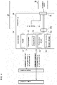
- FIG. 1 is a schematic block diagram of an image sensor 1 according to an embodiment of the present invention.
- the image sensor 1 will be briefly described first with reference to FIG. 1 .
- the image sensor 1 includes a body module 20 to which a lens module 10 is attachable.
- the image sensor 1 is connected to a host device 50 for automatic inspection and process control when in use.
- the host device 50 is a computer with a program installed for using the image sensor 1.
- the host device 50 is typically connected to multiple image sensors 1.
- the body module 20 includes an imaging device 21 and a controller 22 attached to a housing.
- the lens module 10 includes an optical system 11, a heater 13, a temperature sensor 15, and a nonvolatile memory 16 attached to another housing.
- the body module 20 includes a connector 20c.
- the lens module 10 includes a connector 10c to be fitted to the connector 20c in the body module 20 for attaching the lens module 10 to the body module 20.
- the connector 10c is connected to the components in the lens module 10, and the connector 20c is connected to the controller 22 in the body module 20, as schematically indicated by solid and dashed lines in FIG. 1 .
- the image sensor 1 allows a liquid lens 12, the heater 13, the temperature sensor 15, and the nonvolatile memory 16 to be electrically connected to the controller 22 when the lens module 10 is attached to the body module 20 to have the connector 10c and the connector 20c fitted together.
- the optical system 11 combines lenses to allow light from an inspection target to form an image on the imaging surface of the imaging device 21.
- the optical system 11 includes the liquid lens 12 with refractive power controllable in response to a different voltage being applied.
- the heater 13 heats the liquid lens 12.
- the heater 13 may be a device that can control the amount of heat, such as a resistor or a Peltier device.
- the temperature sensor 15 detects the temperature of the liquid lens 12.
- the temperature sensor 15 is a resistance temperature detector or a temperature sensor integrated circuit (IC).
- the nonvolatile memory 16 stores property information about the liquid lens 12. The property information will be described in detail later.
- the image sensor 1 with the above module structure (structure in which the lens module 10 including the optical system 11 including the liquid lens 12 is disconnectable from the body module 20 including the controller 22) allows property information about the individual liquid lens 12 to be set in a short time.
- the nonvolatile memory 16 typically uses a serial bus or a serial interface such as a serial peripheral interface (SPI) or an inter-integrated circuit (I 2 C), which can transmit information with a small number of signal lines, and may be a serial electrically erasable programmable read-only memory (EEPROM).
- SPI serial peripheral interface
- I 2 C inter-integrated circuit
- the imaging device 21 is a two-dimensional image sensing device such as a complementary metal-oxide-semiconductor (CMOS) image sensing device or a charge-coupled device (CCD) image sensing device.
- CMOS complementary metal-oxide-semiconductor
- CCD charge-coupled device
- the imaging device 21 may be a color image sensing device or a monochrome image sensing device.
- the controller 22 causes the image sensor 1 to operate as a device capable of, for example, performing visual inspection of an inspection target or reading characters, a barcode, and other information on the surface of an inspection target.
- the controller 22 includes, for example, a driver IC for generating an application voltage for the liquid lens 12 and a microcontroller.
- the controller 22 in the image sensor 1 is designed (programmed) to perform a property information reading process, a temperature adjustment process, a refractive power control process, and an image analysis process.
- the property information reading process includes reading property information from the nonvolatile memory 16 in the lens module 10 and storing the property information into the controller 22 (memory in the controller 22).
- the controller 22 performs the property information reading process when the image sensor 1 is powered on.
- the temperature adjustment process includes controlling the heater 13 to cause the temperature of the liquid lens 12 detected by the temperature sensor 15 to reach an inspection temperature.
- the inspection temperature is predetermined as the temperature of the liquid lens 12 during the refractive power control process and the image analysis process (described later).
- the inspection temperature is higher (e.g., 60 °C) than the temperature of the liquid lens 12 that is not intentionally heated but is affected by heat from the controller 22.
- the controller 22 starts the temperature adjustment process in response to an instruction from the host device 50 for starting the temperature adjustment process, and ends the process in response to an instruction from the host device 50 for ending the temperature adjustment process.
- the temperature adjustment process may be any process for adjusting the temperature of the liquid lens 12 to nearly the inspection temperature.
- the temperature adjustment process may thus involve, for example, switching on and off the current or the voltage to be supplied to the heater 13 or performing a proportional-integral-derivative (PID) control of the current or the voltage to be supplied to the heater 13.
- PID proportional-integral-derivative
- the refractive power control process is performed by the controller 22 in response to an instruction from the host device 50, together with designation of a target refractive power, for changing the refractive power.
- the target refractive power refers to a target value for the refractive power of the liquid lens 12.
- the liquid lens 12 included in the image sensor 1 has refractive power P at temperature T with application voltage V expressed by a linear expression in terms of application voltage V, where the term of degree one has a coefficient of quadratic expression S(T) in terms of temperature T, and the term of degree zero has a coefficient of quadratic expression Y(T) in terms of temperature T.
- Y T y 2 ⁇ T 2 + y 1 ⁇ T + y 0
- S(Tp) and Y(Tp) are stored (set) in the nonvolatile memory 16 in the lens module 10 as property information.
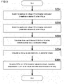
- the controller 22 is designed (programmed) to perform the refractive power control process shown in FIG. 2 .
- the controller 22 starting the refractive power control process in response to an instruction from the host device 50 for changing the refractive power first calculates, using the property information (obtained property information in the figure) read from the nonvolatile memory 16 in the property information reading process, the application voltage that causes the liquid lens 12 to have the refractive power matching the target refractive power (step S101). The controller 22 then applies the calculated application voltage to the liquid lens 12 (step S102) and ends the refractive power control process ( FIG. 2 ).
- the image analysis process shown in FIG. 3 is performed by the controller 22 in response to an image analysis instruction from the host device 50.
- the controller 22 starting the image analysis process in response to the image analysis instruction from the host device 50 first determines whether a wait period has elapsed (step S201). More specifically, the controller 22 determines whether the elapsed time period after the completion of the last refractive power control process is longer than or equal to the wait period (step S201).
- the wait period is predetermined based on the period (hereafter, a response period) taken for the optical system 11 to have the refractive power corresponding to a set voltage after a change in the application voltage to the liquid lens 12 with the inspection temperature.
- the wait period is typically the response period.
- step S201 When the wait period has elapsed (Yes in step S201), the controller 22 obtains image data representing an inspection target from the imaging device 21 (step S202). When the wait period has not elapsed (No in step S201), the controller 22 waits for the wait period to elapse in step S201 before performing step S202.
- step S202 the controller 22 performs preset image processing to analyze the obtained image data and outputs the analysis result to the host device 50 (step S203).
- step S203 the controller 22 ends the image analysis process.
- FIG. 4 is a schematic block diagram of an inspection system 40 prepared for setting the property information for the image sensor 1 (lens module 10). As illustrated, the inspection system 40 prepared for setting the property information for the image sensor 1 includes an inspection jig 30 and an inspection device 35.
- the inspection jig 30 has a similar structure to the body module 20 excluding the controller 22. More specifically, the inspection jig 30 can receive the lens module 10.
- the inspection jig 30 includes a connector 30c to be fitted to the connector 10c in the lens module 10 attached (hereafter also referred to as an attached module 10).
- the inspection jig 30 also includes an imaging device 31. When the lens module 10 is attached to the inspection jig 30, the imaging device 31 and the optical system 11 in the attached module 10 are in the same positional relationship as the imaging device 21 and the optical system 11 in the lens module 10 attached to the body module 20.
- the inspection jig 30 also includes a connector 32.
- the connector 32 is connected to the connector 30c and the imaging device 31 to allow the inspection device 35 to be connected to the liquid lens 12, the temperature sensor 15, the nonvolatile memory 16, and the imaging device 31 when the connector 32 is connected to the cable from the inspection device 35.
- the inspection device 35 performs a property information setting process for obtaining property information about the liquid lens 12 in the attached module 10 and writing the obtained information onto the nonvolatile memory 16 in the attached module 10.
- the attached module 10 refers to the lens module 10 attached to the inspection jig 30.
- FIG. 5 is a flowchart of the property information setting process performed by the inspection device 35.
- the property information setting process is performed for the attached module 10 and the inspection jig 30 controlled to have a predetermined temperature (25 °C in the present embodiment).
- the inspection device 35 has preset values for the coefficients s 2 , si, y 2 , and y 1 with no or small variations resulting from differences between the individual liquid lenses 12 in the coefficients in Formulas 2 and 3 described above.
- the property information setting process starts by searching for an application voltage V1 that causes an imaging workpiece 1 to be in focus (step S301) and searching for an application voltage V2 that causes an imaging workpiece 2 to be in focus (step S302).
- the imaging workpieces 1 and 2 refer to objects to be used for focus adjustment placed at installation distances 1 and 2.
- the property information setting process in the present embodiment includes steps S301 and S302 for repeatedly changing the application voltage for the liquid lens 12 and analyzing the image data received from the imaging device 31 to search for the application voltage that maximizes the contrast between adjacent pixels, and setting the search results as the application voltages V1 and V2.
- Steps S301 and S302 may be any processing for searching for the application voltages for focusing.
- the slope a and the intercept b are calculated for the line indicating the relationship between the refractive powers 1 and 2 and the application voltages V1 and V2 (the line indicating the refractive power versus the application voltage in FIG. 5 ) (step S303). More specifically, as shown in FIG. 6 , the slope a and the intercept b are calculated for the line passing through the coordinate point (application voltage V1, refractive power 1) and the coordinate point (application voltage V2, refractive power 2) in the Cartesian coordinates having the vertical axis indicating the refractive power and the horizontal axis indicating the application voltage.
- This formula is an expression for so resulting from transforming Formula 2 in which S(T) is replaced by a.
- This formula is an expression for yo resulting from transforming Formula 3 in which Y(T) is replaced by b.
- step S304 Upon ending of the processing in step S304, S(Tp) and V(Tp) are calculated based on the so and yo values calculated in step S304, the predetermined s 2 , s 1 , y 2 , and y 1 values, and the inspection temperature Tp using Formulas 2 and 3 described above (step S305). The calculated values are then written onto the nonvolatile memory 16 in the attached module 10 as property information (step S305). The property information setting process thus ends.
- the lens module 10 including the optical system 11 including the liquid lens 12 is disconnectable from the body module 20 including the controller 22.
- the lens module 10 disconnected from the body module 20 can have the liquid lens 12 unaffected by heat from the controller 22, thus allowing accurate property information for the individual liquid lens 12 used in each image sensor 1 to be obtained in a short time.
- the lens module 10 includes the nonvolatile memory 16 for storing the accurate property information.
- the controller 22 in the image sensor 1 (the controller 22 in the body module 20 with the lens module 10 attached) can correct the application voltage for the liquid lens 12 to reflect differences between the individual liquid lenses 12.
- the liquid lens 12 is heated to the inspection temperature by the heater 13.
- the response period of the liquid lens 12 is typically shorter at higher temperatures.
- the image sensor 1 thus takes a shorter period from a change in the application voltage to achieving focus than an image sensor that does not adjust the temperature of the liquid lens 12.
- the image sensor 1 may be modified variously.
- the image sensor 1 may be modified to include the nonvolatile memory 16 for storing all the coefficient values in Formulas 2 and 3 (s 2 , s 1 , s 0 , y 2 , y 1 , and y 0 ) as property information and the controller 22 for calculating the application voltage to be applied to the liquid lens 12 based on the property information and the inspection temperature.
- the image sensor 1 may be modified to include the nonvolatile memory 16 for storing the so and yo values (or in other words, the values with variations resulting from differences between the individual liquid lenses 12) as property information and the controller 22 for calculating the application voltage to be applied to the liquid lens 12 based on the preset coefficient values (the values of s 2 , si, y 2 , and y 1 ), the property information, and the inspection temperature.
- the nonvolatile memory 16 for storing the so and yo values (or in other words, the values with variations resulting from differences between the individual liquid lenses 12) as property information
- the controller 22 for calculating the application voltage to be applied to the liquid lens 12 based on the preset coefficient values (the values of s 2 , si, y 2 , and y 1 ), the property information, and the inspection temperature.
- the property information may be information indicating all or some of the coefficient values in Formula 5 or 6 below.
- each of these coefficient values may be determined (selected) based on, for example, the degrees of variations resulting from differences between the individual liquid lenses 12.
- the property information may be information indicating all or some of the coefficient values in Formula 7 or 8 below, whereas the image sensor 1 may be modified to include the controller 22 for calculating the application voltage to be applied to the liquid lens 12 using the inspection temperature.
- n is an integer of 2 or greater.
- the property information may include data including combinations of an application voltage and a refractive power of the liquid lens 12 in response to the application voltage being applied.
- the application voltage may be applied to the liquid lens 12.
- an application voltage may be calculated based on, for example, a weighted average of two different application voltages associated with the two different refractive powers closest to the target refractive power, and the calculated application voltage may be applied to the liquid lens 12.
- the property information may not directly indicate the relationship between the refractive power and the application voltage.
- the property information may indicate the relationship between a value correlated with the refractive power (e.g., a working distance) and the application voltage.
- the attached module 10 When setting the property information for the nonvolatile memory 16, the attached module 10 may be controlled to have the inspection temperature Tp, and the second property information setting process shown in FIG. 7 may be performed instead of the property information setting process ( FIG. 5 ) described above.
- the second property information setting process includes steps S401 and S402, which are identical to steps S301 and S302 in the property information setting process.
- the attached module 10 When the attached module 10 is controlled to have the inspection temperature Tp, the slope and the intercept for the line indicating the refractive power versus the application voltage, or indicating the relationship between the refractive powers 1 and 2 and the application voltages V1 and V2, are respectively used as S(Tp) and V(Tp) (refer to Formula 1 described above).
- the slope and the intercept for the line indicating the refractive power versus the application voltage are thus written onto the nonvolatile memory 16 in the attached module 10 as S(Tp) for the slope and V(Tp) for the intercept (step S403), instead of steps S303 to S305.
- the body module 20 in the image sensor 1 may include a module including the imaging device 21 and a module including the controller 22.
- the body module 20 may include a unit for controlling the heater 13 separately from the controller 22. Further, the heater 13 may be included in the body module 20, or the image sensor 1 may be modified to start adjusting the temperature of the liquid lens 12 when powered on.
- An image sensor (1) comprising:
Landscapes
- Physics & Mathematics (AREA)
- General Physics & Mathematics (AREA)
- Optics & Photonics (AREA)
- Engineering & Computer Science (AREA)
- Multimedia (AREA)
- Signal Processing (AREA)
- Nonlinear Science (AREA)
- Electromagnetism (AREA)
- Automatic Focus Adjustment (AREA)
- Studio Devices (AREA)
- Electrochromic Elements, Electrophoresis, Or Variable Reflection Or Absorption Elements (AREA)
Abstract
Description
- The present invention relates to an image sensor including a liquid lens.
- A variety of recent optical apparatuses (e.g., imaging apparatuses) include liquid lenses. A liquid lens is an optical component containing a conductive water solution and a nonconductive oil sealed in a lens holder, with the oil-water interface deforming to change the refractive power in response to a voltage applied.
- The liquid lens has the refractive power versus application voltage characteristics that are dependent on temperature. Thus, the refractive power of the liquid lens may deviate from an intended value under heat from an ambient environment around the optical apparatus or from the optical apparatus energized with electricity. To avoid this, a heater may be used for maintaining the liquid lens at a constant temperature (refer to, for example, Patent Literature 1). However, individual liquid lenses have different properties. The individual liquid lenses controlled to have a constant temperature may have different refractive powers in response to the same voltage applied.
- Patent Literature 1:
U.S. Patent Application Publication No. 2017/0090076 - As described above, individual liquid lenses have different properties. The individual liquid lenses controlled to have a constant temperature may thus have different refractive powers in response to the same voltage applied. Producing image sensors that can correct the application voltage reflecting such differences between individual liquid lenses thus involves obtaining accurate correction information for individual image sensors (liquid lenses) by measuring the optical properties of the liquid lenses in a constant temperature environment. An image sensor used for automatic inspection and process control includes an image processing unit, such as a microprocessor unit (MPU) or a digital signal processor (DSP). The image processing unit in operation generates heat, causing the temperature of the liquid lens to rise. Accurate correction information is difficult to obtain using the image processing unit in the image sensor. Correction information may be obtained after the temperature of the liquid lens rising under heat from the image processing is saturated. In this case, obtaining correction information for individual image sensors (liquid lenses) takes time.
- In response to the above issue, one or more aspects of the present invention are directed to an image sensor that corrects the application voltage to reflect differences between individual liquid lenses and can be produced efficiently.
- An image sensor according to one aspect of the present invention includes an imaging device, an optical system including a liquid lens to form an image of an object on an imaging surface of the imaging device, a temperature sensor that detects a temperature of the liquid lens, a heater that heats the liquid lens, a temperature adjuster that controls the heater to adjust the temperature of the liquid lens detected by the temperature sensor to a predetermined temperature, a nonvolatile memory storing property information about the liquid lens, a refractive power controller that determines, based on a target refractive power and the property information stored in the nonvolatile memory, an application voltage applicable to the liquid lens adjusted to have the predetermined temperature and applies the application voltage to the liquid lens to control a refractive power of the liquid lens to match the target refractive power, and an image processor that performs image processing on image data received from the imaging device. At least the optical system, the nonvolatile memory, and the temperature sensor are disconnectable from a body module including at least the refractive power controller and the image processor.
- More specifically, the image sensor includes a module (hereafter, a lens module) including the optical system including the liquid lens. The lens module is disconnectable from the body module that includes the image processor for performing image processing on image data received from the imaging device. The lens module disconnected from the body module can have the liquid lens unaffected by heat from the controller, thus allowing the liquid lens to be at a constant temperature during property measurement. This allows accurate property information to be obtained in a short time for determining the application voltage. The lens module includes the nonvolatile memory for storing the accurate property information and the temperature sensor for detecting the temperature of the liquid lens. The image sensor with this structure corrects the application voltage to reflect differences between individual liquid lenses and can be produced efficiently.
- Further, the image sensor includes the heater for heating the liquid lens to the predetermined temperature. A response period of the liquid lens is typically shorter at higher temperatures. The image sensor thus takes a shorter period from a change in the application voltage to achieving focus than an image sensor that does not adjust the temperature of the liquid lens. The response period refers to a period taken for the optical system to have the refractive power corresponding to a set voltage after a change in the application voltage to the liquid lens.
- The property information stored in the nonvolatile memory may be any information that can be used to determine the application voltage to be applied to the liquid lens to cause the liquid lens at the predetermined temperature to achieve the target refractive power. The property information may thus include relational information indicating a relationship between the refractive power of the liquid lens at the predetermined temperature and the application voltage. The relational information may indicate a relational expression indicating a relationship between the refractive power of the liquid lens at the predetermined temperature and the application voltage. The relational information may include data including combinations indicating a relationship between the refractive power of the liquid lens at the predetermined temperature and the application voltage (combinations of the application voltage and the refractive power).
- In the image sensor, the property information may include a part of relational information indicating a relationship between the refractive power of the liquid lens at the predetermined temperature and the application voltage, and the refractive power controller may determine the application voltage applicable to the liquid lens based on a preset other part of the relational information, the property information read from the nonvolatile memory, and the target refractive power. The relational information may include a first parameter and a second parameter having a smaller variation resulting from an individual difference in the liquid lens than the first parameter, and the part of the relational information may include the first parameter.
- The image sensor according to the above aspects of the present invention corrects the application voltage to reflect differences between individual liquid lenses and can be produced efficiently.
-
-
FIG. 1 is a schematic block diagram of an image sensor according to an embodiment of the present invention. -
FIG. 2 is a flowchart of a refractive power control process performed by a controller in the image sensor. -
FIG. 3 is a flowchart of an image analysis process performed by the controller in the image sensor. -
FIG. 4 is a schematic block diagram of an inspection system prepared for setting property information for the image sensor. -
FIG. 5 is a flowchart of a property information setting process performed by an inspection device in the inspection system. -
FIG. 6 is a graph describing step S303 in the property information setting process. -
FIG. 7 is a flowchart of a second property information setting process for setting the property information. - Embodiments of the present invention will now be described with reference to the drawings.
-
FIG. 1 is a schematic block diagram of animage sensor 1 according to an embodiment of the present invention. Theimage sensor 1 will be briefly described first with reference toFIG. 1 . - The
image sensor 1 according to the present embodiment includes abody module 20 to which alens module 10 is attachable. Theimage sensor 1 is connected to ahost device 50 for automatic inspection and process control when in use. Thehost device 50 is a computer with a program installed for using theimage sensor 1. Thehost device 50 is typically connected tomultiple image sensors 1. - The
body module 20 includes animaging device 21 and acontroller 22 attached to a housing. Thelens module 10 includes anoptical system 11, aheater 13, atemperature sensor 15, and anonvolatile memory 16 attached to another housing. As illustrated, thebody module 20 includes aconnector 20c. Thelens module 10 includes aconnector 10c to be fitted to theconnector 20c in thebody module 20 for attaching thelens module 10 to thebody module 20. Further, theconnector 10c is connected to the components in thelens module 10, and theconnector 20c is connected to thecontroller 22 in thebody module 20, as schematically indicated by solid and dashed lines inFIG. 1 . More specifically, theimage sensor 1 allows aliquid lens 12, theheater 13, thetemperature sensor 15, and thenonvolatile memory 16 to be electrically connected to thecontroller 22 when thelens module 10 is attached to thebody module 20 to have theconnector 10c and theconnector 20c fitted together. - The
optical system 11 combines lenses to allow light from an inspection target to form an image on the imaging surface of theimaging device 21. Theoptical system 11 includes theliquid lens 12 with refractive power controllable in response to a different voltage being applied. - The
heater 13 heats theliquid lens 12. Theheater 13 may be a device that can control the amount of heat, such as a resistor or a Peltier device. Thetemperature sensor 15 detects the temperature of theliquid lens 12. Thetemperature sensor 15 is a resistance temperature detector or a temperature sensor integrated circuit (IC). - The
nonvolatile memory 16 stores property information about theliquid lens 12. The property information will be described in detail later. Theimage sensor 1 with the above module structure (structure in which thelens module 10 including theoptical system 11 including theliquid lens 12 is disconnectable from thebody module 20 including the controller 22) allows property information about the individualliquid lens 12 to be set in a short time. Thenonvolatile memory 16 typically uses a serial bus or a serial interface such as a serial peripheral interface (SPI) or an inter-integrated circuit (I2C), which can transmit information with a small number of signal lines, and may be a serial electrically erasable programmable read-only memory (EEPROM). - The
imaging device 21 is a two-dimensional image sensing device such as a complementary metal-oxide-semiconductor (CMOS) image sensing device or a charge-coupled device (CCD) image sensing device. Theimaging device 21 may be a color image sensing device or a monochrome image sensing device. - The
controller 22 causes theimage sensor 1 to operate as a device capable of, for example, performing visual inspection of an inspection target or reading characters, a barcode, and other information on the surface of an inspection target. Thecontroller 22 includes, for example, a driver IC for generating an application voltage for theliquid lens 12 and a microcontroller. - Based on the above, the
image sensor 1 according to the present embodiment will now be described in more detail. - The
controller 22 in theimage sensor 1 is designed (programmed) to perform a property information reading process, a temperature adjustment process, a refractive power control process, and an image analysis process. - The property information reading process includes reading property information from the
nonvolatile memory 16 in thelens module 10 and storing the property information into the controller 22 (memory in the controller 22). Thecontroller 22 performs the property information reading process when theimage sensor 1 is powered on. - The temperature adjustment process includes controlling the
heater 13 to cause the temperature of theliquid lens 12 detected by thetemperature sensor 15 to reach an inspection temperature. The inspection temperature is predetermined as the temperature of theliquid lens 12 during the refractive power control process and the image analysis process (described later). The inspection temperature is higher (e.g., 60 °C) than the temperature of theliquid lens 12 that is not intentionally heated but is affected by heat from thecontroller 22. - The
controller 22 starts the temperature adjustment process in response to an instruction from thehost device 50 for starting the temperature adjustment process, and ends the process in response to an instruction from thehost device 50 for ending the temperature adjustment process. The temperature adjustment process may be any process for adjusting the temperature of theliquid lens 12 to nearly the inspection temperature. The temperature adjustment process may thus involve, for example, switching on and off the current or the voltage to be supplied to theheater 13 or performing a proportional-integral-derivative (PID) control of the current or the voltage to be supplied to theheater 13. - The refractive power control process is performed by the
controller 22 in response to an instruction from thehost device 50, together with designation of a target refractive power, for changing the refractive power. The target refractive power refers to a target value for the refractive power of theliquid lens 12. - The property information stored (set) in the
nonvolatile memory 16 in thelens module 10 will now be described before the refractive power control process is described in detail. - As shown in
Formulas 1 to 3 below, theliquid lens 12 included in theimage sensor 1 according to the present embodiment has refractive power P at temperature T with application voltage V expressed by a linear expression in terms of application voltage V, where the term of degree one has a coefficient of quadratic expression S(T) in terms of temperature T, and the term of degree zero has a coefficient of quadratic expression Y(T) in terms of temperature T.


- The values of s2, si, y2, and y1 have almost no variations resulting from differences between the individual
liquid lenses 12, whereas the values of so and yo have relatively large variations resulting from differences between the individualliquid lenses 12. The values of S(T) and Y(T) have variations resulting from differences between the individualliquid lenses 12. When S(Tp) and Y(Tp) at inspection temperature Tp are determined, the application voltage for accurately (with almost no control errors resulting from differences between the individual liquid lenses 12) controlling the refractive power of theliquid lens 12 at the inspection temperature Tp is calculated usingFormula 1. - Thus, in the
image sensor 1 according to the present embodiment, S(Tp) and Y(Tp) are stored (set) in thenonvolatile memory 16 in thelens module 10 as property information. - The
controller 22 is designed (programmed) to perform the refractive power control process shown inFIG. 2 . - More specifically, the
controller 22 starting the refractive power control process in response to an instruction from thehost device 50 for changing the refractive power first calculates, using the property information (obtained property information in the figure) read from thenonvolatile memory 16 in the property information reading process, the application voltage that causes theliquid lens 12 to have the refractive power matching the target refractive power (step S101). Thecontroller 22 then applies the calculated application voltage to the liquid lens 12 (step S102) and ends the refractive power control process (FIG. 2 ). - The image analysis process shown in
FIG. 3 is performed by thecontroller 22 in response to an image analysis instruction from thehost device 50. - More specifically, the
controller 22 starting the image analysis process in response to the image analysis instruction from thehost device 50 first determines whether a wait period has elapsed (step S201). More specifically, thecontroller 22 determines whether the elapsed time period after the completion of the last refractive power control process is longer than or equal to the wait period (step S201). The wait period is predetermined based on the period (hereafter, a response period) taken for theoptical system 11 to have the refractive power corresponding to a set voltage after a change in the application voltage to theliquid lens 12 with the inspection temperature. The wait period is typically the response period. - When the wait period has elapsed (Yes in step S201), the
controller 22 obtains image data representing an inspection target from the imaging device 21 (step S202). When the wait period has not elapsed (No in step S201), thecontroller 22 waits for the wait period to elapse in step S201 before performing step S202. - Upon ending the processing in step S202, the
controller 22 performs preset image processing to analyze the obtained image data and outputs the analysis result to the host device 50 (step S203). Upon ending the processing in step S203, thecontroller 22 ends the image analysis process. - The procedure for setting the property information for the image sensor 1 (lens module 10) will now be described.
-
FIG. 4 is a schematic block diagram of aninspection system 40 prepared for setting the property information for the image sensor 1 (lens module 10). As illustrated, theinspection system 40 prepared for setting the property information for theimage sensor 1 includes aninspection jig 30 and aninspection device 35. - The
inspection jig 30 has a similar structure to thebody module 20 excluding thecontroller 22. More specifically, theinspection jig 30 can receive thelens module 10. Theinspection jig 30 includes aconnector 30c to be fitted to theconnector 10c in thelens module 10 attached (hereafter also referred to as an attached module 10). Theinspection jig 30 also includes animaging device 31. When thelens module 10 is attached to theinspection jig 30, theimaging device 31 and theoptical system 11 in the attachedmodule 10 are in the same positional relationship as theimaging device 21 and theoptical system 11 in thelens module 10 attached to thebody module 20. - The
inspection jig 30 also includes aconnector 32. Theconnector 32 is connected to theconnector 30c and theimaging device 31 to allow theinspection device 35 to be connected to theliquid lens 12, thetemperature sensor 15, thenonvolatile memory 16, and theimaging device 31 when theconnector 32 is connected to the cable from theinspection device 35. - The
inspection device 35 performs a property information setting process for obtaining property information about theliquid lens 12 in the attachedmodule 10 and writing the obtained information onto thenonvolatile memory 16 in the attachedmodule 10. As described (defined) above, the attachedmodule 10 refers to thelens module 10 attached to theinspection jig 30. -
FIG. 5 is a flowchart of the property information setting process performed by theinspection device 35. - The property information setting process is performed for the attached
module 10 and theinspection jig 30 controlled to have a predetermined temperature (25 °C in the present embodiment). Theinspection device 35 has preset values for the coefficients s2, si, y2, and y1 with no or small variations resulting from differences between the individualliquid lenses 12 in the coefficients inFormulas 2 and 3 described above. - As shown in
FIG. 5 , the property information setting process starts by searching for an application voltage V1 that causes animaging workpiece 1 to be in focus (step S301) and searching for an application voltage V2 that causes animaging workpiece 2 to be in focus (step S302). As schematically shown inFIG. 4 , theimaging workpieces installation distances liquid lens 12 corresponding to the installation distance n (n = 1, 2) is hereafter referred to as a refractive power n. - The property information setting process in the present embodiment includes steps S301 and S302 for repeatedly changing the application voltage for the
liquid lens 12 and analyzing the image data received from theimaging device 31 to search for the application voltage that maximizes the contrast between adjacent pixels, and setting the search results as the application voltages V1 and V2. Steps S301 and S302 may be any processing for searching for the application voltages for focusing. - Upon ending of the processing in step S302, the slope a and the intercept b are calculated for the line indicating the relationship between the
refractive powers FIG. 5 ) (step S303). More specifically, as shown inFIG. 6 , the slope a and the intercept b are calculated for the line passing through the coordinate point (application voltage V1, refractive power 1) and the coordinate point (application voltage V2, refractive power 2) in the Cartesian coordinates having the vertical axis indicating the refractive power and the horizontal axis indicating the application voltage. - The so value in
Formula 2 and the yo value in Formula 3 above are then calculated based on, for example, the calculated slope a and the calculated intercept b (step S304). More specifically, in step S304, the so value is calculated by substituting the known numbers (the s2, si, a, and T values) into the formula so = a - s2 × T2 - s1 × T. This formula is an expression for so resulting from transformingFormula 2 in which S(T) is replaced by a. In step S304, the yo value is also calculated by substituting the known numbers (the y2, y1, b, and T values) into the formula yo = b - y2 × T2 - y1 × T. This formula is an expression for yo resulting from transforming Formula 3 in which Y(T) is replaced by b. - Upon ending of the processing in step S304, S(Tp) and V(Tp) are calculated based on the so and yo values calculated in step S304, the predetermined s2, s1, y2, and y1 values, and the inspection temperature
Tp using Formulas 2 and 3 described above (step S305). The calculated values are then written onto thenonvolatile memory 16 in the attachedmodule 10 as property information (step S305). The property information setting process thus ends. - In the
image sensor 1 according to the present embodiment described above, thelens module 10 including theoptical system 11 including theliquid lens 12 is disconnectable from thebody module 20 including thecontroller 22. Thelens module 10 disconnected from thebody module 20 can have theliquid lens 12 unaffected by heat from thecontroller 22, thus allowing accurate property information for the individualliquid lens 12 used in eachimage sensor 1 to be obtained in a short time. Thelens module 10 includes thenonvolatile memory 16 for storing the accurate property information. Thus, thecontroller 22 in the image sensor 1 (thecontroller 22 in thebody module 20 with thelens module 10 attached) can correct the application voltage for theliquid lens 12 to reflect differences between the individualliquid lenses 12. - Further, in the
image sensor 1, theliquid lens 12 is heated to the inspection temperature by theheater 13. The response period of theliquid lens 12 is typically shorter at higher temperatures. Theimage sensor 1 thus takes a shorter period from a change in the application voltage to achieving focus than an image sensor that does not adjust the temperature of theliquid lens 12. - The
image sensor 1 according to the above embodiments may be modified variously. For example, theimage sensor 1 may be modified to include thenonvolatile memory 16 for storing all the coefficient values inFormulas 2 and 3 (s2, s1, s0, y2, y1, and y0) as property information and thecontroller 22 for calculating the application voltage to be applied to theliquid lens 12 based on the property information and the inspection temperature. Theimage sensor 1 may be modified to include thenonvolatile memory 16 for storing the so and yo values (or in other words, the values with variations resulting from differences between the individual liquid lenses 12) as property information and thecontroller 22 for calculating the application voltage to be applied to theliquid lens 12 based on the preset coefficient values (the values of s2, si, y2, and y1), the property information, and the inspection temperature. - For the
liquid lens 12 with the refractive power that cannot be closely approximated by Formula 1 (a linear expression in terms of V), the property information may be information indicating all or some of the coefficient values in Formula 5 or 6 below. When the property information is information indicating some of the coefficient values, each of these coefficient values may be determined (selected) based on, for example, the degrees of variations resulting from differences between the individualliquid lenses 12.

- The property information may be information indicating all or some of the coefficient values in Formula 7 or 8 below, whereas the
image sensor 1 may be modified to include thecontroller 22 for calculating the application voltage to be applied to theliquid lens 12 using the inspection temperature.

- In Formulas 5 to 8, n is an integer of 2 or greater. Ci(T) (i = 0 to n) in Formula 7 is a function of temperature T indicating the coefficient value of the term of degree i in Formula 5, which expresses refractive power P as an expression of degree n. Di(T) (i = 0 to n) in Formula 8 is a function of temperature T indicating the coefficient value of the term of degree i in Formula 6, which expresses application voltage V as an expression of degree n.
- The property information may include data including combinations of an application voltage and a refractive power of the
liquid lens 12 in response to the application voltage being applied. When the data including combinations of the application voltage and the refractive power used as property information includes an application voltage associated with the target refractive power, the application voltage may be applied to theliquid lens 12. When the data does not include an application voltage associated with the target refractive power, an application voltage may be calculated based on, for example, a weighted average of two different application voltages associated with the two different refractive powers closest to the target refractive power, and the calculated application voltage may be applied to theliquid lens 12. The property information may not directly indicate the relationship between the refractive power and the application voltage. For example, the property information may indicate the relationship between a value correlated with the refractive power (e.g., a working distance) and the application voltage. - When setting the property information for the
nonvolatile memory 16, the attachedmodule 10 may be controlled to have the inspection temperature Tp, and the second property information setting process shown inFIG. 7 may be performed instead of the property information setting process (FIG. 5 ) described above. The second property information setting process includes steps S401 and S402, which are identical to steps S301 and S302 in the property information setting process. When the attachedmodule 10 is controlled to have the inspection temperature Tp, the slope and the intercept for the line indicating the refractive power versus the application voltage, or indicating the relationship between therefractive powers Formula 1 described above). In the second property information setting process, the slope and the intercept for the line indicating the refractive power versus the application voltage are thus written onto thenonvolatile memory 16 in the attachedmodule 10 as S(Tp) for the slope and V(Tp) for the intercept (step S403), instead of steps S303 to S305. - The
body module 20 in theimage sensor 1 may include a module including theimaging device 21 and a module including thecontroller 22. Thebody module 20 may include a unit for controlling theheater 13 separately from thecontroller 22. Further, theheater 13 may be included in thebody module 20, or theimage sensor 1 may be modified to start adjusting the temperature of theliquid lens 12 when powered on. - An image sensor (1), comprising:
- an imaging device (21);
- an optical system (11) including a liquid lens (12) to form an image of an object on an imaging surface of the imaging device (21);
- a temperature sensor (15) configured to detect a temperature of the liquid lens (12);
- a heater (13) configured to heat the liquid lens (12);
- a temperature adjuster (22) configured to control the heater (13) to adjust the temperature of the liquid lens (12) detected by the temperature sensor (15) to a predetermined temperature;
- a nonvolatile memory (16) storing property information about the liquid lens (12);
- a refractive power controller (22) configured to determine, based on a target refractive power and the property information stored in the nonvolatile memory (16), an application voltage applicable to the liquid lens (12) adjusted to have the predetermined temperature and apply the application voltage to the liquid lens (12) to control a refractive power of the liquid lens (12) to match the target refractive power; and
- an image processor (22) configured to perform image processing on image data received from the imaging device (21),
- wherein at least the optical system (11), the nonvolatile memory (16), and the temperature sensor (15) are disconnectable from a body module (20) including at least the refractive power controller (22) and the image processor (22).
-
- 1
- image sensor
- 10c, 20c, 30c, 32
- connector
- 10
- lens module
- 11
- optical system
- 12
- liquid lens
- 13
- heater
- 15
- temperature sensor
- 16
- nonvolatile memory
- 20
- body module
- 21, 31
- imaging device
- 22
- controller
- 30
- inspection jig
- 35
- inspection device
- 40
- inspection system
- 50
- host device
Claims (5)
- An image sensor, comprising:an imaging device;an optical system including a liquid lens to form an image of an object on an imaging surface of the imaging device;a temperature sensor configured to detect a temperature of the liquid lens;a heater configured to heat the liquid lens;a temperature adjuster configured to control the heater to adjust the temperature of the liquid lens detected by the temperature sensor to a predetermined temperature;a nonvolatile memory storing property information about the liquid lens;a refractive power controller configured to determine, based on a target refractive power and the property information stored in the nonvolatile memory, an application voltage applicable to the liquid lens adjusted to have the predetermined temperature and apply the application voltage to the liquid lens to control a refractive power of the liquid lens to match the target refractive power; andan image processor configured to perform image processing on image data received from the imaging device,wherein at least the optical system, the nonvolatile memory, and the temperature sensor are disconnectable from a body module including at least the refractive power controller and the image processor.
- The image sensor according to claim 1, wherein
the property information includes relational information indicating a relationship between the refractive power of the liquid lens at the predetermined temperature and the application voltage. - The image sensor according to claim 1, whereinthe property information includes a part of relational information indicating a relationship between the refractive power of the liquid lens at the predetermined temperature and the application voltage, andthe refractive power controller determines the application voltage applicable to the liquid lens based on a preset other part of the relational information, the property information read from the nonvolatile memory, and the target refractive power.
- The image sensor according to claim 3, whereinthe relational information includes a first parameter and a second parameter having a smaller variation resulting from an individual difference in the liquid lens than the first parameter, andthe part of the relational information includes the first parameter.
- The image sensor according to any one of claims 2 to 4, wherein
the relational information indicates a relational expression indicating a relationship between the refractive power of the liquid lens at the predetermined temperature and the application voltage.
Applications Claiming Priority (2)
| Application Number | Priority Date | Filing Date | Title |
|---|---|---|---|
| JP2019135083A JP7247802B2 (en) | 2019-07-23 | 2019-07-23 | image sensor |
| PCT/JP2020/023992 WO2021014843A1 (en) | 2019-07-23 | 2020-06-18 | Image sensor |
Publications (2)
| Publication Number | Publication Date |
|---|---|
| EP3975540A1 true EP3975540A1 (en) | 2022-03-30 |
| EP3975540A4 EP3975540A4 (en) | 2023-06-28 |
Family
ID=74193161
Family Applications (1)
| Application Number | Title | Priority Date | Filing Date |
|---|---|---|---|
| EP20844311.9A Pending EP3975540A4 (en) | 2019-07-23 | 2020-06-18 | Image sensor |
Country Status (5)
| Country | Link |
|---|---|
| US (1) | US11750902B2 (en) |
| EP (1) | EP3975540A4 (en) |
| JP (1) | JP7247802B2 (en) |
| CN (1) | CN114073064B (en) |
| WO (1) | WO2021014843A1 (en) |
Families Citing this family (1)
| Publication number | Priority date | Publication date | Assignee | Title |
|---|---|---|---|---|
| CN117032612B (en) * | 2023-08-02 | 2024-03-15 | 诺曼智慧(北京)科技有限公司 | Interactive teaching method, device, terminal and medium based on high beam imaging learning machine |
Family Cites Families (15)
| Publication number | Priority date | Publication date | Assignee | Title |
|---|---|---|---|---|
| JP2006135588A (en) | 2004-11-05 | 2006-05-25 | Fuji Photo Film Co Ltd | Adapter device and camera unit |
| JP4750626B2 (en) * | 2006-05-31 | 2011-08-17 | シチズンホールディングス株式会社 | Automatic focusing device |
| WO2009011384A1 (en) * | 2007-07-19 | 2009-01-22 | Nikon Corporation | Optical element, optical system, optical device and imaging method |
| JP2009080187A (en) * | 2007-09-25 | 2009-04-16 | Nikon Corp | Optical apparatus and imaging method |
| JP2009246932A (en) * | 2008-03-13 | 2009-10-22 | Olympus Imaging Corp | Photographing lens unit and electronic apparatus using it |
| JP4402163B1 (en) * | 2009-04-06 | 2010-01-20 | 株式会社オプトエレクトロニクス | Liquid lens optical body and optical information reader |
| KR101143558B1 (en) * | 2011-12-08 | 2012-06-14 | 주식회사 동운아나텍 | Liquid crystal lens driving device, terminal device comprising same and temperature control method thereof |
| WO2015001634A1 (en) * | 2013-07-03 | 2015-01-08 | 富士機械製造株式会社 | Imaging device and production equipment |
| US9575221B2 (en) | 2013-12-31 | 2017-02-21 | Cognex Corporation | Systems and methods reduce temperature induced drift effects on a liquid lens |
| US10690816B2 (en) * | 2013-12-31 | 2020-06-23 | Cognex Corporation | Systems and methods reduce temperature induced drift effects on a liquid lens |
| DE102014104029B3 (en) * | 2014-03-24 | 2015-04-23 | Sick Ag | Optoelectronic device and method for taking sharp images |
| WO2016202392A1 (en) * | 2015-06-17 | 2016-12-22 | Optotune Ag | Temperature drift compensation for liquid lenses |
| WO2018042759A1 (en) * | 2016-09-02 | 2018-03-08 | 富士フイルム株式会社 | Lens device, imaging device, and method for correcting defocus in lens device |
| WO2019183147A1 (en) * | 2018-03-20 | 2019-09-26 | Corning Incorporated | Self-heating liquid lens and self-heating methods for the same |
| KR102614746B1 (en) * | 2018-05-23 | 2023-12-15 | 엘지이노텍 주식회사 | Liquid lens, camera module including the lens, and method for controlling the liquid lens |
-
2019
- 2019-07-23 JP JP2019135083A patent/JP7247802B2/en active Active
-
2020
- 2020-06-18 US US17/621,381 patent/US11750902B2/en active Active
- 2020-06-18 CN CN202080045809.XA patent/CN114073064B/en active Active
- 2020-06-18 EP EP20844311.9A patent/EP3975540A4/en active Pending
- 2020-06-18 WO PCT/JP2020/023992 patent/WO2021014843A1/en not_active Ceased
Also Published As
| Publication number | Publication date |
|---|---|
| CN114073064B (en) | 2024-08-27 |
| US11750902B2 (en) | 2023-09-05 |
| US20220394164A1 (en) | 2022-12-08 |
| JP2021019322A (en) | 2021-02-15 |
| JP7247802B2 (en) | 2023-03-29 |
| WO2021014843A1 (en) | 2021-01-28 |
| CN114073064A (en) | 2022-02-18 |
| EP3975540A4 (en) | 2023-06-28 |
Similar Documents
| Publication | Publication Date | Title |
|---|---|---|
| EP3004957B1 (en) | A method for calibrating an image capture device | |
| KR101143558B1 (en) | Liquid crystal lens driving device, terminal device comprising same and temperature control method thereof | |
| CN102650720A (en) | Infrared lens unit and infrared camera system provided with the infrared lens unit | |
| US20190236339A1 (en) | Detection apparatus and non-transitory computer readable medium | |
| US12313863B2 (en) | Image sensor | |
| US11750902B2 (en) | Image sensor | |
| US10362303B2 (en) | Sensor-assisted autofocus calibration | |
| CN115552331A (en) | An Intelligent Way to Track Focus in Machine Vision Applications | |
| CN114397778A (en) | Display heating compensation method, device and system | |
| CN117622960A (en) | Width measurement and correction methods and devices | |
| US20190154510A1 (en) | Method for Determining a Temperature without Contact and Infrared Measuring System | |
| CN112616021A (en) | Anti-shake holder, anti-shake method and camera module | |
| US11689804B2 (en) | Image sensor | |
| US11438479B2 (en) | Semiconductor device, replacement part, and image forming apparatus | |
| EP3952284B1 (en) | Image sensor | |
| CN114414060B (en) | Measuring device | |
| JP6864850B2 (en) | Image forming device | |
| US20190302023A1 (en) | Polarization analysis apparatus and control method of polarization analysis apparatus | |
| CN111936927A (en) | Control device, imaging device, system, control method, and program |
Legal Events
| Date | Code | Title | Description |
|---|---|---|---|
| STAA | Information on the status of an ep patent application or granted ep patent |
Free format text: STATUS: THE INTERNATIONAL PUBLICATION HAS BEEN MADE |
|
| PUAI | Public reference made under article 153(3) epc to a published international application that has entered the european phase |
Free format text: ORIGINAL CODE: 0009012 |
|
| STAA | Information on the status of an ep patent application or granted ep patent |
Free format text: STATUS: REQUEST FOR EXAMINATION WAS MADE |
|
| 17P | Request for examination filed |
Effective date: 20211222 |
|
| AK | Designated contracting states |
Kind code of ref document: A1 Designated state(s): AL AT BE BG CH CY CZ DE DK EE ES FI FR GB GR HR HU IE IS IT LI LT LU LV MC MK MT NL NO PL PT RO RS SE SI SK SM TR |
|
| DAV | Request for validation of the european patent (deleted) | ||
| DAX | Request for extension of the european patent (deleted) | ||
| REG | Reference to a national code |
Ref country code: DE Ref legal event code: R079 Free format text: PREVIOUS MAIN CLASS: H04N0005225000 Ipc: H04N0023520000 |
|
| A4 | Supplementary search report drawn up and despatched |
Effective date: 20230530 |
|
| RIC1 | Information provided on ipc code assigned before grant |
Ipc: H04N 23/60 20230101ALI20230523BHEP Ipc: G02B 3/12 20060101ALI20230523BHEP Ipc: H04N 23/52 20230101AFI20230523BHEP |
|
| STAA | Information on the status of an ep patent application or granted ep patent |
Free format text: STATUS: EXAMINATION IS IN PROGRESS |
|
| 17Q | First examination report despatched |
Effective date: 20250331 |