EP3975455A1 - Determining correctness of actually received timestamp - Google Patents
Determining correctness of actually received timestamp Download PDFInfo
- Publication number
- EP3975455A1 EP3975455A1 EP20197698.2A EP20197698A EP3975455A1 EP 3975455 A1 EP3975455 A1 EP 3975455A1 EP 20197698 A EP20197698 A EP 20197698A EP 3975455 A1 EP3975455 A1 EP 3975455A1
- Authority
- EP
- European Patent Office
- Prior art keywords
- ecu
- validator
- timestamp
- actually received
- time
- Prior art date
- Legal status (The legal status is an assumption and is not a legal conclusion. Google has not performed a legal analysis and makes no representation as to the accuracy of the status listed.)
- Granted
Links
Images

Classifications
-
- H—ELECTRICITY
- H04—ELECTRIC COMMUNICATION TECHNIQUE
- H04J—MULTIPLEX COMMUNICATION
- H04J3/00—Time-division multiplex systems
- H04J3/02—Details
- H04J3/06—Synchronising arrangements
- H04J3/0635—Clock or time synchronisation in a network
- H04J3/0638—Clock or time synchronisation among nodes; Internode synchronisation
- H04J3/0652—Synchronisation among time division multiple access [TDMA] nodes, e.g. time triggered protocol [TTP]
- H04J3/0655—Synchronisation among time division multiple access [TDMA] nodes, e.g. time triggered protocol [TTP] using timestamps
-
- H—ELECTRICITY
- H04—ELECTRIC COMMUNICATION TECHNIQUE
- H04J—MULTIPLEX COMMUNICATION
- H04J3/00—Time-division multiplex systems
- H04J3/02—Details
- H04J3/14—Monitoring arrangements
-
- H—ELECTRICITY
- H04—ELECTRIC COMMUNICATION TECHNIQUE
- H04L—TRANSMISSION OF DIGITAL INFORMATION, e.g. TELEGRAPHIC COMMUNICATION
- H04L12/00—Data switching networks
- H04L12/28—Data switching networks characterised by path configuration, e.g. LAN [Local Area Networks] or WAN [Wide Area Networks]
- H04L12/40—Bus networks
-
- H—ELECTRICITY
- H04—ELECTRIC COMMUNICATION TECHNIQUE
- H04L—TRANSMISSION OF DIGITAL INFORMATION, e.g. TELEGRAPHIC COMMUNICATION
- H04L12/00—Data switching networks
- H04L12/28—Data switching networks characterised by path configuration, e.g. LAN [Local Area Networks] or WAN [Wide Area Networks]
- H04L12/46—Interconnection of networks
- H04L12/4604—LAN interconnection over a backbone network, e.g. Internet, Frame Relay
- H04L12/462—LAN interconnection over a bridge based backbone
-
- H—ELECTRICITY
- H04—ELECTRIC COMMUNICATION TECHNIQUE
- H04L—TRANSMISSION OF DIGITAL INFORMATION, e.g. TELEGRAPHIC COMMUNICATION
- H04L12/00—Data switching networks
- H04L12/66—Arrangements for connecting between networks having differing types of switching systems, e.g. gateways
-
- H—ELECTRICITY
- H04—ELECTRIC COMMUNICATION TECHNIQUE
- H04L—TRANSMISSION OF DIGITAL INFORMATION, e.g. TELEGRAPHIC COMMUNICATION
- H04L41/00—Arrangements for maintenance, administration or management of data switching networks, e.g. of packet switching networks
- H04L41/14—Network analysis or design
- H04L41/147—Network analysis or design for predicting network behaviour
-
- H—ELECTRICITY
- H04—ELECTRIC COMMUNICATION TECHNIQUE
- H04L—TRANSMISSION OF DIGITAL INFORMATION, e.g. TELEGRAPHIC COMMUNICATION
- H04L41/00—Arrangements for maintenance, administration or management of data switching networks, e.g. of packet switching networks
- H04L41/14—Network analysis or design
- H04L41/149—Network analysis or design for prediction of maintenance
-
- H—ELECTRICITY
- H04—ELECTRIC COMMUNICATION TECHNIQUE
- H04L—TRANSMISSION OF DIGITAL INFORMATION, e.g. TELEGRAPHIC COMMUNICATION
- H04L43/00—Arrangements for monitoring or testing data switching networks
- H04L43/08—Monitoring or testing based on specific metrics, e.g. QoS, energy consumption or environmental parameters
- H04L43/0852—Delays
-
- H—ELECTRICITY
- H04—ELECTRIC COMMUNICATION TECHNIQUE
- H04L—TRANSMISSION OF DIGITAL INFORMATION, e.g. TELEGRAPHIC COMMUNICATION
- H04L43/00—Arrangements for monitoring or testing data switching networks
- H04L43/10—Active monitoring, e.g. heartbeat, ping or trace-route
- H04L43/106—Active monitoring, e.g. heartbeat, ping or trace-route using time related information in packets, e.g. by adding timestamps
-
- H—ELECTRICITY
- H04—ELECTRIC COMMUNICATION TECHNIQUE
- H04L—TRANSMISSION OF DIGITAL INFORMATION, e.g. TELEGRAPHIC COMMUNICATION
- H04L43/00—Arrangements for monitoring or testing data switching networks
- H04L43/16—Threshold monitoring
Definitions
- the present invention is directed to a method for determining a correctness of an actually received timestamp provided by a first ECU of a communication network using a validator, and a validator configured to carry out the method.
- ECUs electronice control units
- ASIL Automotive Safety Integrity Level
- the Automotive Safety Integrity Level is a risk classification scheme defined by ISO 26262 - Functional Safety for Road Vehicles.
- the ASIL classification comprises five safety levels, starting from QM with the lowest safety requirements to ASIL D having the highest safety requirements.
- CAN-FD Controller Area Network Flexible Data-Rate
- Flexray can be used together.
- Ethernet is a family of computer networking technologies commonly used in local area networks (LAN), metropolitan area networks (MAN) and wide area networks (WAN). It was commercially introduced in 1980 and first communication standardized in 1983 as IEEE (Institute of Electrical and Electronics Engineers) 802.3.
- Flexray is an automotive network communication protocol developed by the Flexray Consortium to govern on-board automotive computing. It is designed to be faster and more reliable than CAN (Controller Area Network) and TTP (Time Triggered Protocol).
- the Flexray standard is now a set of ISO standards, ISO 17458-1 to 17458-5.
- CAN FD is a data-communication protocol typically used for passing sensor data and control information between different parts of electronic instrumentation and a control system. This protocol is used in modern high-performance vehicles.
- CAN FD is an extension to the original CAN bus protocol that was specified in ISO 11898-1.
- time synchronization of an Ethernet bus is done according to IEEE 802.1AS for a TSN (time sensitive network) and IEEE 1588 with respect to the PTP (Precision Time Protocol).
- TSN time sensitive network
- PTP Precision Time Protocol
- the Flexray bus internal wall clock does not have any safety integrity and is QM.
- the QM criterion means that in this case the measures required by a normal quality management system (ISO/TS 16949) are sufficient.
- the Flexray message needs to be used with respective messages from Ethernet and CAN-FD. If Flexray messages with QM timestamps are used with the respective ASIL B or ASIL D timestamps of Ethernet (and/or CAN FD), it may result into non-fulfillment of "Freedom from Interference" functional safety requirements (ISO 26262) for highly automated vehicles according to ASIL D.
- the object of the present invention is to provide a method for evaluating the synchronization of multiple connected communication bus and their respective ECUs with each other providing a high safety level, e.g. a safety level fulfilling ASIL D requirements, and fulfill the "Freedom from Interference" functional safety requirements according to ISO 26262.
- the object is solved by a method for determining a correctness of an actually received timestamp provided by a first ECU of a communication network using a validator.
- the communication network comprises a master clock, the first ECU having a first slave clock, the validator having a second slave clock, and a first communication bus connecting the first ECU, the validator and the master clock to each other.
- the first ECU uses a first communication standard having a deterministic scheme. That is, it is sufficient if only the connection between the first ECU and the validator has a deterministic transmission scheme. Moreover, it is possible and sufficient that the first standard has a static segment of a time cycle with a deterministic scheme.
- the method for determining the correctness of the actually received timestamp at the validator, the timestamp being provided by the first ECU of the communication network comprises synchronizing, at the first ECU, a time of the first slave clock to a global time of the master clock, synchronizing, at the validator, a time of the second slave clock to the global time of the master clock, predicting, at the validator, a timestamp to be received in an actual communication cycle from the first ECU based on the deterministic scheme of the communication standard used by the first ECU, and comparing, at the validator, the predicted timestamp with the actually received timestamp from the first ECU.
- Comparing, at the validator, the predicted timestamp with the actually received timestamp provided by the first ECU of the communication network can comprise determining, at the validator, a difference between the predicted timestamp and the actually received timestamp, comparing the difference to a predefined threshold value, and if the difference is smaller than the predefined threshold value, preferably if the difference is in a certain range, determining the correctness of the actually received timestamp.
- the difference between the global time of the predicted timestamp at the validator and the global time of the actually received timestamp can be determined considering a fixed delay between a data acquisition task and a data sending task of the first ECU, wherein the actually received timestamp at the validator is provided by the first ECU during the data acquisition task.
- the difference between the predicted timestamp and the actually received timestamp can be determined using the following formula: GT 2 ⁇ GT 1 ⁇ ⁇ + ⁇
- GT2 is the global time of providing the actually received timestamp by the first ECU.
- GT1 is a global reference time at a start of the actual communication cycle of the first ECU.
- ⁇ is a result received by multiplying a predefined number of slots of the deterministic scheme of the first communication standard used by the first ECU with a fixed duration of the slots.
- ⁇ is the fixed delay between the data acquisition task and the data sending task of the first ECU.
- the actually received timestamp is provided during the data acquisition task by the first ECU. Due to the deterministic behavior of the communication bus connecting the first ECU and the validator, both ⁇ and ⁇ are deterministic and can be determined at pre-compile time.
- the difference between the predicted timestamp and the actually received timestamp can be determined using the following formula: GT_Current ⁇ GT 2 + ⁇
- GT2 is the global time of providing the actually received timestamp by the first ECU.
- ⁇ is the fixed delay between the data acquisition task and the data sending task of the first ECU.
- the actually received timestamp is provided during the data acquisition task by the first ECU.
- GT_Current is a global time of receiving the actually received timestamp at the validator.
- this approach does not provide the same accuracy level as the previous procedure due to a software interrupt latency ⁇ upon querying the current global time at the time the PDU carrying a timestamp that needs to be validated is received (i.e. GT_Current).
- this solution requires typically more computing resources. However, it is simpler from the fact that only one deterministic parameter ⁇ must be provided.
- GT2 is the global time of providing the actually received timestamp by the first ECU.
- GT1 is a global reference time at a start of the actual communication cycle of the first ECU.
- lt1 is a local time of the first slave clock of the first ECU at the start of the actual communication cycle.
- lt2 is a local time of the first slave clock of the first ECU at the time of providing the actually received time stamp by the first ECU.
- the communication network can further comprise a second ECU having a third slave clock, a gateway ECU comprising the validator, and a second communication bus connecting the second ECU via the gateway ECU and the first communication bus to the first ECU.
- the second ECU can use a second communication standard having a higher safety integrity level than the first communication standard used by the first ECU or be validated by other means.
- An integrity of the master clock can be sufficient to fulfill safety requirements of the second communication standard having the higher safety integrity level than the first communication standard.
- the correctness of the actually received timestamp provided by the first ECU can be determined by the validator according to the safety requirements of the second communication standard.
- Synchronizing, at the first ECU, the time of the first slave clock to the global time of the master clock can comprise receiving, at the first ECU, a synchronization message from the master clock such that the time of the first slave clock of the first ECU is synchronized to the global time of the master clock based on the received synchronization message.
- a validator can be provided.
- the validator can be configured to determine a correctness of an actually received timestamp provided by a first ECU of a communication network.
- the communication network can comprise a master clock, the first ECU having a first slave clock, and a first communication bus being configured to connect the first ECU, the validator and the master clock to each other.
- the first ECU can use a first communication standard having a deterministic scheme.
- a time of the first slave clock can be synchronized to a global time of the master clock.
- the validator can comprise a second slave clock, wherein a time of the second slave clock is synchronized to the global time of the master clock.
- the validator can be configured to predict a timestamp to be received in an actual communication cycle from the first ECU based on the deterministic scheme of the communication standard used by the first ECU, and compare the predicted timestamp with an actually received timestamp from the first ECU.
- the validator can be configured to carry out one of the above described methods.
- the validator ensures that time synchronization of the first ECU may achieve a highest possible level of safety integrity according to the safety integrity of the validator. Furthermore, it is ensured that the safety integrity level of the second ECU and the second communication bus will be inherited by the validator and it is ensured that the safety integrity level of the first ECU with the first communication bus, the validator with the gateway ECU and the second ECU with the second communication bus achieve similar and/or the highest possible safety integrity level.
- the communication network 1 shown in figure 1 is a network for transmitting data in an autonomous or automated vehicle, e.g. a car.
- the network 1 comprises two ECUs 2, 3 using a first communication standard, two ECUs 4, 5 using a second communication standard, a gateway ECU 6, an interconnect 7, a master clock 8, a first bus system (i.e. first communication bus) 9 using the first communication standard, and a second bus system (i.e. second communication bus) 10 using the second communication standard.
- first bus system i.e. first communication bus
- second bus system i.e. second communication bus
- the network 1 comprises a first and a second ECU 2, 3 using a first deterministic communication standard, e.g. a Flexray standard as defined in the entry part of the description, a third and a fourth ECU 4, 5 using a second communication standard, e.g. an Ethernet standard (or CAN FD, in the following Ethernet will be used as example for the second communication standard, wherein it is also possible to use CAN FD) as defined in the entry part of the description, and the gateway ECU 6.
- a first deterministic communication standard e.g. a Flexray standard as defined in the entry part of the description
- a third and a fourth ECU 4, 5 using a second communication standard, e.g. an Ethernet standard (or CAN FD, in the following Ethernet will be used as example for the second communication standard, wherein it is also possible to use CAN FD) as defined in the entry part of the description
- a second communication standard e.g. an Ethernet standard (or CAN FD, in the following Ethernet will be used as example
- the first and the second ECU 2, 3 are connected by the first bus system 9 to the master clock 8, respectively. Moreover, the first and the second ECU 2, 3 are also connected to the gateway ECU 6 via the first bus system 9, respectively.
- the first bus system 9 uses the first communication standard. In the above example, the first bus system 9 would be a deterministic Flexray bus system.
- the third and the fourth ECU 4, 5 are connected to the interconnect 7 via the second bus system 10, respectively, wherein the second bus system 10 uses the second communication standard.
- the second bus system 10 would be an Ethernet bus system.
- the third and the fourth ECU 4, 5 are also connected by the second bus system 10 to the gateway ECU 6 via the interconnect 7, respectively.
- the interconnect 7, which would be an Ethernet interconnect (e.g. a switch) in the above example, is configured to connect the third and the fourth ECU 4, 5 of the network 1 to the gateway ECU 6, respectively, by using packet switching to receive data from and/or forward data to the gateway ECU 6.
- Ethernet interconnect e.g. a switch
- the master clock 8 is connected to the first bus system 9 and to the second bus system 10 via the interconnect 7.
- the master clock 8 is configured to provide a global or master time to the ECUs 2, 3, 4, 5 each comprising a slave clock 21, 31, 41, 51 as well as to the gateway ECU 6 also comprising a slave clock 61.
- the master clock 8 is thus configured to provide timing signals to synchronize the slave clocks 21, 31, 41, 51, 61 of the devices 2, 3, 6 using the first communication standard and the devices 4, 5, 6 using the second communication standard of the network 1.
- the gateway ECU 6 which would be a Flexray-Ethernet gateway ECU in the above example, is configured to provide interoperability between the first and the second ECU 2, 3 using the first communication standard, here the Flexray standard, and the third and the fourth ECU 4, 5 using the second communication standard, here the Ethernet standard. Therefore, the gateway ECU 6 is configured to do unidirectional or bidirectional protocol translation between the first and the second communication standard.
- the second communication standard has a higher safety integrity level than the first communication standard.
- the Ethernet standard used by the third and the fourth ECU 4, 5 can be ASIL D qualified, whereas the Flexray standard used by the first and the second ECU 2, 3 is solely QM.
- the gateway ECU 6 the first and the second ECU 2, 3 and the third and the fourth ECU 4, 5 can communicate with each other. However, since they use communication standards with different safety integrity levels, this is not possible according to a "Freedom from Interference" functional safety requirements (ISO 26262) for highly automated vehicles according to ASIL D.
- ISO 26262 Freedom from Interference functional safety requirements
- the method for determining the correctness of the actually received timestamp provided by the first and the second ECU 2, 3 of the communication network 1 is provided. That is, the timestamps provided by the first and the second ECU 2, 3 can be qualified to a higher safety level, here ASIL D, by the gateway ECU 6.
- ASIL D a higher safety level
- the gateway ECU 6 comprises a validator 62, in the present case a central validator, being configured to carry out the method.
- Figure 2 shows a flowchart depicting steps of the method.
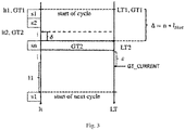
- Figure 3 depicts schematically a communication scheme of the first ECU 2 with the validator 62 on the gateway ECU 6 using the first communication standard and a first and a second possibility for determining the correctness of the actually received timestamp.
- the communication network 1 comprises the master clock 8, the ECUs 2, 3, 4, 5 having the slave clocks 21, 31, 41, 51, respectively, the validator 6 having the slave clock 61, and the validator 62, and the first communication bus system 9 connecting the first and the second ECU 2, 3, the validator 62 and the master clock 8 to each other.
- the first communication standard used by the first and the second ECU 2,3 has a deterministic scheme. That is, the underlying communication protocol always passes through the same sequence of states at a predefined and fixed time. Thus, it is possible to predict when a data packet sent from the first or the second ECU 2, 3 using the first communication standard will arrive at a receiver, here at the validator 62 of the gateway ECU 6.
- the communication on the first bus system 9 runs in cycles. Each of these cycles is divided into different segments including a static and a dynamic segment.
- each ECU 2, 3 using the first communication standard has its specific slot, i.e. time window, in which it can send messages. It must not exceed the length of its slot. If the message is too long, another cycle that is assigned to the respective ECU or the dynamic segment must be used to continue the message.
- a time of the slave clocks 21, 31, 41, 51, 61 of the ECUs 2, 3, 4, 5 and the gateway ECU 6 is synchronized to a global time of the master clock 8, respectively.
- Synchronizing, at the first and the second ECU 2, 3, the time of the respective slave clocks 21, 31 to the global time of the master clock 8 can comprise receiving, at the first and the second ECU 2, 3, respectively, a synchronization message from the master clock 8 such that the local time of the respective slave clocks 21, 31 of the first and the second ECU 2, 3 are synchronized to the global time of the master clock 8 based on the received synchronization message.
- the validator 62 predicts a timestamp to be received in an actual communication cycle from the first and/or the second ECU 2, 3 based on the deterministic scheme of the first communication standard used by the first and the second ECU 2, 3.
- the validator 62 compares the predicted timestamp with the actually received timestamp from the first and/or the second ECU 2, 3.
- the third step S3 of comparing, at the validator 62, the predicted timestamp with the actually received timestamp comprises determining, at the validator 62, a difference between the predicted timestamp and the actually received timestamp, comparing the difference to a predefined threshold value, and if the difference is smaller than the predefined threshold value, preferably if the difference is in a certain range, determining the correctness of the actually received timestamp by a validation marking, where an integrity flag is set, or any other mean that is transparent to the receiver of the information.
- FIG 3 two timelines are shown. On the left side of figure 3 a timeline for the first ECU 1, on which the local time It of the slave clock 21 of the first ECU 1 is depicted, and on the right side of figure 3 a time line for the validator 62, on which the local time LT of the slave clock 61 of the gateway ECU 6 is depicted, are shown.
- Every synchronized ECU 2, 3, 4, 5, 6 has after synchronization the same global time available typically referred to a local instance of global time, i.e. a local clock, derived from its underlying local hardware counter, e.g. an oscillator, that maintains the synchronized time or global time, respectively.
- a local clock derived from its underlying local hardware counter, e.g. an oscillator, that maintains the synchronized time or global time, respectively.
- a reference-tuple lt1, GT1, LT1, GT1 Upon synchronization a reference-tuple lt1, GT1, LT1, GT1 is generated that contains the local time lt1, LT1, and the corresponding synchronized time GT1.
- This reference tuple lt1, GT1, LT1, GT1 is used to derive the current synchronized time at any desired point in time.
- the first step S1 of synchronizing the slave clocks 21, 31, 41, 51, 61 generates merely a reference that can be used to translate from local time lt, LT to the synchronized or global time GT.
- GT2 can be the global time of providing the actually received timestamp read from the local slave clock 21 by the first ECU 2 to the measured data.
- GT1 can be the global time at the start of the actual communication cycle of the first ECU 2.
- lt1 can be a local time of the slave clock 21 of the first ECU 2 at the start of the actual communication cycle.
- lt2 can be a local time of the slave clock 21 of the first ECU 2 at the time of providing the actually received time stamp by the first ECU 2.
- the communication scheme of the first communication standard comprises, as explained above, a deterministic or static part comprising slots s1 - sn, wherein each slot has a fixed and predefined duration, and an indeterministic or dynamic part 11.
- a timestamp i.e. the actually received timestamp originating from the local instance of global time, is attached to data sent in the static part of the data acquisition task and then send during a data sending task from the first ECU 2 via the first bus system 9 to the gateway ECU 6.
- a fixed delay ⁇ is provided according to the first communication standard.
- the difference between the global time of the predicted timestamp and the global time of the actually received timestamp can be determined considering the fixed delay ⁇ between the data acquisition task and the data sending task of the first ECU 2, wherein the timestamp actually received by the validator 62 for validation purpose is provided during the data acquisition task by the first ECU 2. This is true for both possibilities for determining the correctness of the actually provided timestamp.
- the difference between the predicted timestamp and the actually received timestamp can be determined using the following formula: GT 2 ⁇ GT 1 ⁇ ⁇ + ⁇
- GT2 is the global time of providing the actually received timestamp by the first ECU 2.
- GT1 is a global reference time.
- GT1 is a global time at a start of the actual communication cycle of the first ECU 2.
- ⁇ is a result received by multiplying a predefined number of slots n of the deterministic scheme of the first communication standard used by the first ECU 2 with a fixed duration of the slots l Slot . It takes the scheduling of the messages into account, such that GT1 + ⁇ corresponds to the instance in global time when the message is scheduled for transmission by the first ECU 2.
- ⁇ is the fixed delay between the data acquisition task and the data sending task of the first ECU 2.
- the actually received timestamp is provided during the data acquisition task by the first ECU 2. Therefore, GT2 - ⁇ corresponds to the instance in global time when the message is scheduled for transmission by the first ECU 2.
- the formula makes use of this fact by comparing both instances in time to each other. Thereby, the integrity of the timestamp can be checked.
- the first ECU 2 can acquire data from an external unit, e.g. a sensor, and add the actually received timestamp to the acquired data.
- the timestamp being substantially the global time at which the data was acquired from the first ECU 2.
- the data acquired during the data acquisition task plus the added actually received timestamp are sent from the first ECU 2 to the validator 62.
- the validator then calculates the difference with the above formula and compares the difference with a predefined threshold value. If the difference is smaller than the defined threshold value, i.e. a jitter of the first ECU 2 is smaller than the threshold value, the validator 62 demines the actually provided timestamp of the first ECU 2 to be correct, i.e. to fulfill the safety requirements of the second communication standard. Therefore, the validator 62 is configured to qualify the actually received timestamps to the safety level of the second communication standard, here ASIL D.
- the difference between the predicted timestamp and the actually received timestamp can be determined using the following formula: GT_Current ⁇ GT 2 + ⁇
- GT2 is the global time of providing the actually received timestamp by the first ECU 2 and ⁇ is the fixed delay between the data acquisition task and the data sending task of the first ECU 2.
- the actually received timestamp is provided during the data acquisition task.
- GT_Current is a global time of receiving the actually received timestamp at the validator 62. From a conceptual point of view the two solutions are identical, however, they may differ from implementation effort and achievable reliability of a certain accuracy-level.
- the validator 62 is compared by the validator 62 with a predefined threshold value, here the uncertainty ⁇ , and if the difference is smaller the threshold value, i.e. a jitter of the first ECU 2 is smaller than the threshold value, the validator 62 demines the actually provided timestamp of the first ECU 2 to be correct, i.e. to fulfill the safety requirements of the second communication standard. Therefore, the validator 62 is configured to qualify the actually received timestamps to the safety level of the second communication standard, here ASIL D.
- ASIL D the safety level of the second communication standard
- the correctness of the actually received timestamp can be determined by the validator 62 according to the safety requirements of the second communication standard.
- the Flexray bus 9 receives a synchronization message from the grandmaster 8.
- the Flexray bus 9 is internally synchronized based on the given synchronization message.
- the Ethernet communication bus 10 provides synchronization via IEEE802.1 AS or similar protocols with ASIL D for the central validator 62.
- the central validator 62 on the gateway ECU 6 works as a comparator between the Ethernet communication bus 9 and the Flexray communication bus 10, that compares received timestamps to the expected values for those timestamps.
- the central validator 62 on one side ensures that the Ethernet communication is verified according to ASIL D and on the other hand takes QM input from the Flexray bus 9 and validates it with the clock of the Ethernet.
- the central validator 62 use the deterministic scheduling of the Flexray messages to verify the correctness of the Flexray timestamps provided as QM, and qualify the given timestamps to ASIL D.
- the gateway ECU 6, here the validator 62 can predict the timestamps which might be coming in next cycle from the Flexray bus 9. The prediction of timestamps is done based on the deterministic static message data including the fixed delay between data acquisition task and data sending task of the Flexray standard. Hence the predicted timestamps are compared to the received time stamps to ensure the jitter in the Flexray communication bus 9 is not greater than highly automated vehicle time synchronization threshold, i.e. 1ms.
Landscapes
- Engineering & Computer Science (AREA)
- Computer Networks & Wireless Communication (AREA)
- Signal Processing (AREA)
- Environmental & Geological Engineering (AREA)
- Health & Medical Sciences (AREA)
- Cardiology (AREA)
- General Health & Medical Sciences (AREA)
- Synchronisation In Digital Transmission Systems (AREA)
- Small-Scale Networks (AREA)
- Selective Calling Equipment (AREA)
Abstract
Description
- The present invention is directed to a method for determining a correctness of an actually received timestamp provided by a first ECU of a communication network using a validator, and a validator configured to carry out the method.
- With an increasing complexity of autonomous or automated vehicles, multiple communication bus are used by different electronic control units (ECUs) to ensure that autonomous or automated driving functions fulfill safety requirements, e.g. requirements needed to fulfill a so-called Automotive Safety Integrity Level (ASIL).
- The Automotive Safety Integrity Level is a risk classification scheme defined by ISO 26262 - Functional Safety for Road Vehicles. The ASIL classification comprises five safety levels, starting from QM with the lowest safety requirements to ASIL D having the highest safety requirements.
- For example, in an autonomous or automated vehicle Ethernet, CAN-FD (Controller Area Network Flexible Data-Rate) and Flexray can be used together.
- Ethernet is a family of computer networking technologies commonly used in local area networks (LAN), metropolitan area networks (MAN) and wide area networks (WAN). It was commercially introduced in 1980 and first communication standardized in 1983 as IEEE (Institute of Electrical and Electronics Engineers) 802.3. Flexray is an automotive network communication protocol developed by the Flexray Consortium to govern on-board automotive computing. It is designed to be faster and more reliable than CAN (Controller Area Network) and TTP (Time Triggered Protocol). The Flexray standard is now a set of ISO standards, ISO 17458-1 to 17458-5. CAN FD is a data-communication protocol typically used for passing sensor data and control information between different parts of electronic instrumentation and a control system. This protocol is used in modern high-performance vehicles. CAN FD is an extension to the original CAN bus protocol that was specified in ISO 11898-1.
- In the state of the art, time synchronization of an Ethernet bus is done according to IEEE 802.1AS for a TSN (time sensitive network) and IEEE 1588 with respect to the PTP (Precision Time Protocol). However, for time synchronization via PTP there are several measures that can be taken in addition to the respective standards, so that the integrity of the synchronization process and thus the integrity of the distributed time-base can be ensured.
- However, the Flexray bus internal wall clock does not have any safety integrity and is QM. The QM criterion means that in this case the measures required by a normal quality management system (ISO/TS 16949) are sufficient. The Flexray message needs to be used with respective messages from Ethernet and CAN-FD. If Flexray messages with QM timestamps are used with the respective ASIL B or ASIL D timestamps of Ethernet (and/or CAN FD), it may result into non-fulfillment of "Freedom from Interference" functional safety requirements (ISO 26262) for highly automated vehicles according to ASIL D.
- With the ISO 26262 "Freedom from Interference", it can be demonstrated that a (sub-) system with a less critical ASIL level (e.g. ASIL A) cannot influence a system with a more critical ASIL level (e.g. ASIL C). The goal is to prevent that a system with a higher error rate (e.g. ASIL A) drives a system in which a lower error rate (e.g. ASIL C) is required.
- Therefore, as for autonomous and automated vehicles, one of the most complex and difficult tasks is that multiple connected communication bus and their respective ECUs need to be synchronized with each other to fulfill these requirements.
- In the light of this state of the art, the object of the present invention is to provide a method for evaluating the synchronization of multiple connected communication bus and their respective ECUs with each other providing a high safety level, e.g. a safety level fulfilling ASIL D requirements, and fulfill the "Freedom from Interference" functional safety requirements according to ISO 26262.
- The object is solved by the features of the independent claims. The dependent claims contain preferred further developments of the invention.
- More specifically, the object is solved by a method for determining a correctness of an actually received timestamp provided by a first ECU of a communication network using a validator.
- The communication network comprises a master clock, the first ECU having a first slave clock, the validator having a second slave clock, and a first communication bus connecting the first ECU, the validator and the master clock to each other.
- The first ECU uses a first communication standard having a deterministic scheme. That is, it is sufficient if only the connection between the first ECU and the validator has a deterministic transmission scheme. Moreover, it is possible and sufficient that the first standard has a static segment of a time cycle with a deterministic scheme.
- The method for determining the correctness of the actually received timestamp at the validator, the timestamp being provided by the first ECU of the communication network, comprises synchronizing, at the first ECU, a time of the first slave clock to a global time of the master clock, synchronizing, at the validator, a time of the second slave clock to the global time of the master clock, predicting, at the validator, a timestamp to be received in an actual communication cycle from the first ECU based on the deterministic scheme of the communication standard used by the first ECU, and comparing, at the validator, the predicted timestamp with the actually received timestamp from the first ECU.
- Comparing, at the validator, the predicted timestamp with the actually received timestamp provided by the first ECU of the communication network can comprise determining, at the validator, a difference between the predicted timestamp and the actually received timestamp, comparing the difference to a predefined threshold value, and if the difference is smaller than the predefined threshold value, preferably if the difference is in a certain range, determining the correctness of the actually received timestamp.
- The difference between the global time of the predicted timestamp at the validator and the global time of the actually received timestamp can be determined considering a fixed delay between a data acquisition task and a data sending task of the first ECU, wherein the actually received timestamp at the validator is provided by the first ECU during the data acquisition task.
- More specifically, the difference between the predicted timestamp and the actually received timestamp can be determined using the following formula:

- GT2 is the global time of providing the actually received timestamp by the first ECU. GT1 is a global reference time at a start of the actual communication cycle of the first ECU. Δ is a result received by multiplying a predefined number of slots of the deterministic scheme of the first communication standard used by the first ECU with a fixed duration of the slots. δ is the fixed delay between the data acquisition task and the data sending task of the first ECU. The actually received timestamp is provided during the data acquisition task by the first ECU. Due to the deterministic behavior of the communication bus connecting the first ECU and the validator, both Δ and δ are deterministic and can be determined at pre-compile time.
- Additionally or alternatively, the difference between the predicted timestamp and the actually received timestamp can be determined using the following formula:

- GT2 is the global time of providing the actually received timestamp by the first ECU. δ is the fixed delay between the data acquisition task and the data sending task of the first ECU. The actually received timestamp is provided during the data acquisition task by the first ECU. GT_Current is a global time of receiving the actually received timestamp at the validator.
- In general, this approach does not provide the same accuracy level as the previous procedure due to a software interrupt latency ε upon querying the current global time at the time the PDU carrying a timestamp that needs to be validated is received (i.e. GT_Current). In addition, this solution requires typically more computing resources. However, it is simpler from the fact that only one deterministic parameter δ must be provided.
- The global time of the actually received timestamp can be determined at the first ECU using the following formula:

- GT2 is the global time of providing the actually received timestamp by the first ECU. GT1 is a global reference time at a start of the actual communication cycle of the first ECU. lt1 is a local time of the first slave clock of the first ECU at the start of the actual communication cycle. lt2 is a local time of the first slave clock of the first ECU at the time of providing the actually received time stamp by the first ECU.
- The communication network can further comprise a second ECU having a third slave clock, a gateway ECU comprising the validator, and a second communication bus connecting the second ECU via the gateway ECU and the first communication bus to the first ECU.
- The second ECU can use a second communication standard having a higher safety integrity level than the first communication standard used by the first ECU or be validated by other means.
- An integrity of the master clock can be sufficient to fulfill safety requirements of the second communication standard having the higher safety integrity level than the first communication standard.
- The correctness of the actually received timestamp provided by the first ECU can be determined by the validator according to the safety requirements of the second communication standard.
- Synchronizing, at the first ECU, the time of the first slave clock to the global time of the master clock can comprise receiving, at the first ECU, a synchronization message from the master clock such that the time of the first slave clock of the first ECU is synchronized to the global time of the master clock based on the received synchronization message.
- Furthermore, a validator can be provided. The validator can be configured to determine a correctness of an actually received timestamp provided by a first ECU of a communication network.
- The communication network can comprise a master clock, the first ECU having a first slave clock, and a first communication bus being configured to connect the first ECU, the validator and the master clock to each other.
- The first ECU can use a first communication standard having a deterministic scheme. A time of the first slave clock can be synchronized to a global time of the master clock.
- The validator can comprise a second slave clock, wherein a time of the second slave clock is synchronized to the global time of the master clock.
- The validator can be configured to predict a timestamp to be received in an actual communication cycle from the first ECU based on the deterministic scheme of the communication standard used by the first ECU, and compare the predicted timestamp with an actually received timestamp from the first ECU.
- The above described with reference to the method also applies to the device, i.e. the validator, and vice versa.
- Moreover, the validator can be configured to carry out one of the above described methods.
- In short, by comparing and predicting the timestamp of the first ECU, the validator ensures that time synchronization of the first ECU may achieve a highest possible level of safety integrity according to the safety integrity of the validator. Furthermore, it is ensured that the safety integrity level of the second ECU and the second communication bus will be inherited by the validator and it is ensured that the safety integrity level of the first ECU with the first communication bus, the validator with the gateway ECU and the second ECU with the second communication bus achieve similar and/or the highest possible safety integrity level.
- In the following, a description of an embodiment of the present invention is given with respect to
figures 1 to 3 . - Fig. 1
- depicts schematically a communication network with multiple communication bus used in a vehicle.
- Fig. 2
- depicts schematically a flow chart of a method for determining a correctness of an actually received timestamp provided by a first ECU of the communication network of
figure 1 using a validator. - Fig. 3
- depicts schematically a communication scheme of the first ECU and the validator of
figure 1 . - The
communication network 1 shown infigure 1 is a network for transmitting data in an autonomous or automated vehicle, e.g. a car. - The
network 1 comprises twoECUs ECUs gateway ECU 6, aninterconnect 7, amaster clock 8, a first bus system (i.e. first communication bus) 9 using the first communication standard, and a second bus system (i.e. second communication bus) 10 using the second communication standard. - More specifically, the
network 1 comprises a first and asecond ECU fourth ECU gateway ECU 6. - The first and the
second ECU master clock 8, respectively. Moreover, the first and thesecond ECU gateway ECU 6 via the first bus system 9, respectively. The first bus system 9 uses the first communication standard. In the above example, the first bus system 9 would be a deterministic Flexray bus system. - The third and the
fourth ECU interconnect 7 via thesecond bus system 10, respectively, wherein thesecond bus system 10 uses the second communication standard. In the above example, thesecond bus system 10 would be an Ethernet bus system. Moreover, the third and thefourth ECU second bus system 10 to thegateway ECU 6 via theinterconnect 7, respectively. - The
interconnect 7, which would be an Ethernet interconnect (e.g. a switch) in the above example, is configured to connect the third and thefourth ECU network 1 to thegateway ECU 6, respectively, by using packet switching to receive data from and/or forward data to thegateway ECU 6. - The
master clock 8 is connected to the first bus system 9 and to thesecond bus system 10 via theinterconnect 7. Themaster clock 8 is configured to provide a global or master time to theECUs slave clock gateway ECU 6 also comprising aslave clock 61. Themaster clock 8 is thus configured to provide timing signals to synchronize the slave clocks 21, 31, 41, 51, 61 of thedevices devices network 1. - The
gateway ECU 6, which would be a Flexray-Ethernet gateway ECU in the above example, is configured to provide interoperability between the first and thesecond ECU fourth ECU gateway ECU 6 is configured to do unidirectional or bidirectional protocol translation between the first and the second communication standard. - In the present case, the second communication standard has a higher safety integrity level than the first communication standard. For example, the Ethernet standard used by the third and the
fourth ECU second ECU - As explained above, via the
gateway ECU 6 the first and thesecond ECU fourth ECU - As explained in the entry part of the description, with the ISO 26262 "Freedom from Interference" criterion, it can be demonstrated that a (sub-) system with a less critical ASIL level, here the first bus system 9 with the first and the
second ECU second bus system 10 with the third and thefourth ECU interconnect 7. The goal is to prevent that a system with a higher error rate drives a system in which a lower error rate is required. - Therefore, the method for determining the correctness of the actually received timestamp provided by the first and the
second ECU communication network 1 is provided. That is, the timestamps provided by the first and thesecond ECU gateway ECU 6. - Therefore, the
gateway ECU 6 comprises avalidator 62, in the present case a central validator, being configured to carry out the method. - In the following the method will be described in detail with respect to
figures 2 and3 .Figure 2 shows a flowchart depicting steps of the method.Figure 3 depicts schematically a communication scheme of thefirst ECU 2 with the validator 62 on thegateway ECU 6 using the first communication standard and a first and a second possibility for determining the correctness of the actually received timestamp. - As explained above, the
communication network 1 comprises themaster clock 8, theECUs validator 6 having theslave clock 61, and thevalidator 62, and the first communication bus system 9 connecting the first and thesecond ECU validator 62 and themaster clock 8 to each other. - The first communication standard used by the first and the
second ECU second ECU validator 62 of thegateway ECU 6. - In case the Flexray standard is used, the communication on the first bus system 9 runs in cycles. Each of these cycles is divided into different segments including a static and a dynamic segment.
- In the static segment, each
ECU - This is the deterministic part of the protocol, i.e. of the first communication standard, that ensures that important messages, e.g. steering, brake and so on, are transmitted within a known time.
- To predict, when a data packet will arrive at the
validator 62, in a first step S1 of the method, a time of the slave clocks 21, 31, 41, 51, 61 of theECUs gateway ECU 6 is synchronized to a global time of themaster clock 8, respectively. - Synchronizing, at the first and the
second ECU master clock 8 can comprise receiving, at the first and thesecond ECU master clock 8 such that the local time of the respective slave clocks 21, 31 of the first and thesecond ECU master clock 8 based on the received synchronization message. - In a second step S2, the
validator 62 predicts a timestamp to be received in an actual communication cycle from the first and/or thesecond ECU second ECU - Afterwards, in a third step S3, the
validator 62 compares the predicted timestamp with the actually received timestamp from the first and/or thesecond ECU - The steps S1 to S3 will now be explained in detail with reference to
figure 3 . - As explained above, in
figure 3 two possibilities for determining the correctness of the actually received timestamp are shown. The two possibilities of determining the correctness of the timestamp can be used alternatively or in combination. - However, according to both possibilities, the third step S3 of comparing, at the
validator 62, the predicted timestamp with the actually received timestamp comprises determining, at thevalidator 62, a difference between the predicted timestamp and the actually received timestamp, comparing the difference to a predefined threshold value, and if the difference is smaller than the predefined threshold value, preferably if the difference is in a certain range, determining the correctness of the actually received timestamp by a validation marking, where an integrity flag is set, or any other mean that is transparent to the receiver of the information. - More specifically, in
figure 3 two timelines are shown. On the left side offigure 3 a timeline for thefirst ECU 1, on which the local time It of theslave clock 21 of thefirst ECU 1 is depicted, and on the right side offigure 3 a time line for thevalidator 62, on which the local time LT of theslave clock 61 of thegateway ECU 6 is depicted, are shown. - Every
synchronized ECU master clock 8. - Upon synchronization a reference-tuple lt1, GT1, LT1, GT1 is generated that contains the local time lt1, LT1, and the corresponding synchronized time GT1. This reference tuple lt1, GT1, LT1, GT1 is used to derive the current synchronized time at any desired point in time.
- Thus, in the present case, the first step S1 of synchronizing the slave clocks 21, 31, 41, 51, 61 generates merely a reference that can be used to translate from local time lt, LT to the synchronized or global time GT.
- For the
first ECU 2, the current synchronized time GT2 at the current local time lt2 with lt2 > lt1 is given by:
- GT2 can be the global time of providing the actually received timestamp read from the
local slave clock 21 by thefirst ECU 2 to the measured data. GT1 can be the global time at the start of the actual communication cycle of thefirst ECU 2. lt1 can be a local time of theslave clock 21 of thefirst ECU 2 at the start of the actual communication cycle. lt2 can be a local time of theslave clock 21 of thefirst ECU 2 at the time of providing the actually received time stamp by thefirst ECU 2. - Analogously, for the
gateway ECU 6 and thus for thevalidator 62, the current synchronized time GT2 at the current local time LT2 with LT2 > LT1 is given by:
- Moreover, the communication scheme of the first communication standard comprises, as explained above, a deterministic or static part comprising slots s1 - sn, wherein each slot has a fixed and predefined duration, and an indeterministic or
dynamic part 11. - During a data acquisition task of the first ECU 2 a timestamp, i.e. the actually received timestamp originating from the local instance of global time, is attached to data sent in the static part of the data acquisition task and then send during a data sending task from the
first ECU 2 via the first bus system 9 to thegateway ECU 6. - Between the data sending and the data acquisition task a fixed delay δ is provided according to the first communication standard.
- Therefore, the difference between the global time of the predicted timestamp and the global time of the actually received timestamp can be determined considering the fixed delay δ between the data acquisition task and the data sending task of the
first ECU 2, wherein the timestamp actually received by thevalidator 62 for validation purpose is provided during the data acquisition task by thefirst ECU 2. This is true for both possibilities for determining the correctness of the actually provided timestamp. - More specifically, according to the first possibility, the difference between the predicted timestamp and the actually received timestamp can be determined using the following formula:

- GT2 is the global time of providing the actually received timestamp by the
first ECU 2. GT1 is a global reference time. In the present embodiment, GT1 is a global time at a start of the actual communication cycle of thefirst ECU 2. Δ is a result received by multiplying a predefined number of slots n of the deterministic scheme of the first communication standard used by thefirst ECU 2 with a fixed duration of the slots lSlot . It takes the scheduling of the messages into account, such that GT1 + Δ corresponds to the instance in global time when the message is scheduled for transmission by thefirst ECU 2. As explained above, δ is the fixed delay between the data acquisition task and the data sending task of thefirst ECU 2. The actually received timestamp is provided during the data acquisition task by thefirst ECU 2. Therefore, GT2 - δ corresponds to the instance in global time when the message is scheduled for transmission by thefirst ECU 2. The formula makes use of this fact by comparing both instances in time to each other. Thereby, the integrity of the timestamp can be checked. - During the data acquisition task, the
first ECU 2 can acquire data from an external unit, e.g. a sensor, and add the actually received timestamp to the acquired data. The timestamp being substantially the global time at which the data was acquired from thefirst ECU 2. - During the data sending task, the data acquired during the data acquisition task plus the added actually received timestamp are sent from the
first ECU 2 to thevalidator 62. - The validator then calculates the difference with the above formula and compares the difference with a predefined threshold value. If the difference is smaller than the defined threshold value, i.e. a jitter of the
first ECU 2 is smaller than the threshold value, thevalidator 62 demines the actually provided timestamp of thefirst ECU 2 to be correct, i.e. to fulfill the safety requirements of the second communication standard. Therefore, thevalidator 62 is configured to qualify the actually received timestamps to the safety level of the second communication standard, here ASIL D. - Additionally or alternatively, according to the second possibility, the difference between the predicted timestamp and the actually received timestamp can be determined using the following formula:

- As explained above, GT2 is the global time of providing the actually received timestamp by the
first ECU 2 and δ is the fixed delay between the data acquisition task and the data sending task of thefirst ECU 2. The actually received timestamp is provided during the data acquisition task. GT_Current is a global time of receiving the actually received timestamp at thevalidator 62. From a conceptual point of view the two solutions are identical, however, they may differ from implementation effort and achievable reliability of a certain accuracy-level. - Analogously to the first possibility, the thus received difference is compared by the validator 62 with a predefined threshold value, here the uncertainty ε, and if the difference is smaller the threshold value, i.e. a jitter of the
first ECU 2 is smaller than the threshold value, thevalidator 62 demines the actually provided timestamp of thefirst ECU 2 to be correct, i.e. to fulfill the safety requirements of the second communication standard. Therefore, thevalidator 62 is configured to qualify the actually received timestamps to the safety level of the second communication standard, here ASIL D. - Since an integrity of the
master clock 8 is sufficient to fulfill safety requirements of the second communication standard having the higher safety level than the first communication standard, the correctness of the actually received timestamp can be determined by thevalidator 62 according to the safety requirements of the second communication standard. - The above explanation given with respect to
figure 3 concerning thefirst ECU 2 is also valid for thesecond ECU 3, and if more than twoECUs - In summary, according to the above described embodiment the Flexray bus 9 receives a synchronization message from the
grandmaster 8. The Flexray bus 9 is internally synchronized based on the given synchronization message. TheEthernet communication bus 10 provides synchronization via IEEE802.1 AS or similar protocols with ASIL D for thecentral validator 62. Thecentral validator 62 on thegateway ECU 6 works as a comparator between the Ethernet communication bus 9 and theFlexray communication bus 10, that compares received timestamps to the expected values for those timestamps. Thecentral validator 62 on one side ensures that the Ethernet communication is verified according to ASIL D and on the other hand takes QM input from the Flexray bus 9 and validates it with the clock of the Ethernet. As the Flexray bus 9 is deterministic in nature hence thecentral validator 62 use the deterministic scheduling of the Flexray messages to verify the correctness of the Flexray timestamps provided as QM, and qualify the given timestamps to ASIL D. Thegateway ECU 6, here thevalidator 62, can predict the timestamps which might be coming in next cycle from the Flexray bus 9. The prediction of timestamps is done based on the deterministic static message data including the fixed delay between data acquisition task and data sending task of the Flexray standard. Hence the predicted timestamps are compared to the received time stamps to ensure the jitter in the Flexray communication bus 9 is not greater than highly automated vehicle time synchronization threshold, i.e. 1ms. -
- 1
- communication network
- 2, 3
- ECU using a first communication standard
- 4, 5
- ECU using a second communication standard
- 6
- gateway ECU with validator
- 7
- interconnect, e.g. a switch
- 8
- time grand master/master clock
- 9
- first bus system using the first communication standard
- 10
- second bus system using the second communication standard
- 11
- indeterministic part of first communication standard
- 21
- slave clock of first ECU
- 31
- slave clock of second ECU
- 41
- slave clock of third ECU
- 51
- slave clock of fourth ECU
- 61
- slave clock of validator
- 62
- validator
- GT
- global time
- GT1
- global time at start of cycle
- GT2
- global time at providing/adding actually received timestamp
- GT_current
- global time of receiving actually received timestamp at validator
- lt
- local time at first ECU
- lt1
- local time at start of cycle at first ECU
- lt2
- local time at providing/adding actually received timestamp at first ECU
- LT
- local time at gateway ECU
- LT1
- local time at start of cycle at gateway ECU
- LT2
- local time at gateway ECU of receiving timestamp at the validator
- lSlot
- duration of one slot of first communication standard
- n
- number of slots
- Δ
- result received by multiplying n with lSlot
- δ
- fixed delay between data acquisition task and data sending task
- S1 - S3
- steps of the method
Claims (10)
- Method for determining a correctness of an actually received timestamp provided by a first ECU (2) of a communication network (1) using a validator (62),- wherein the communication network (1) comprises:- a master clock (8), the first ECU (2) having a first slave clock (21), the validator (62) having a second slave clock (61), and a first communication bus (9) connecting the first ECU (2), the validator (62) and the master clock (8) to each other,- wherein the first ECU (2) uses a first communication standard having a deterministic scheme,- the method for determining the correctness of the actually received timestamp at the validator (62), provided by the first ECU (2) of the communication network (1) comprises:- synchronizing (S1), at the first ECU (2), a time of the first slave clock (21) to a global time (GT) of the master clock (8),- synchronizing (S1), at the validator (62), a time of the second slave clock (61) to the global time (GT) of the master clock (8),- predicting (S2), at the validator (62), a timestamp to be received in an actual communication cycle from the first ECU (2) based on the deterministic scheme of the communication standard used by the first ECU (2), and- comparing (S3), at the validator (62), the predicted timestamp with the actually received timestamp from the first ECU (2).
- Method according to claim 1, wherein comparing, at the validator (62), the predicted timestamp with the actually received timestamp provided by the first ECU (2) of the communication network (1) comprises:- determining, at the validator (62), a difference between the predicted timestamp and the actually received timestamp,- comparing the difference to a predefined threshold value, and- if the difference is smaller than the predefined threshold value, preferably if the difference is in a certain range, determining the correctness of the actually received timestamp.
- Method according to claim 2,- wherein the difference between the global time (GT) of the predicted timestamp at validator (62) and the global time (GT) of the actually received timestamp is determined considering a fixed delay (δ) between a data acquisition task and a data sending task of the first ECU (2), wherein the actually received timestamp at the validator (62) is provided by the first ECU (2) during the data acquisition task.
- Method according to claim 3,- wherein the difference between the predicted timestamp and the actually received timestamp is determined using the following formula:
 - wherein:- GT2 is a global time of providing the actually received timestamp by the first ECU (2),- GT1 is a global reference time at a start of the actual communication cycle of the first ECU (2),- Δ is a result received by multiplying a predefined number of slots (n) of the deterministic scheme of the first communication standard used by the first ECU (2) with a fixed duration of the slots (lSlot ), and- δ is the fixed delay between the data acquisition task and the data sending task of the first ECU (2), wherein the actually received timestamp is provided during the data acquisition task by the first ECU (2).
 - Method according to claim 3 or 4, wherein the difference between the predicted timestamp and the actually received timestamp is determined using the following formula:
 - wherein:- GT2 is a global time of providing the actually received timestamp by the first ECU (2),- δ is the fixed delay between the data acquisition task and the data sending task of the first ECU (2), wherein the actually received timestamp is provided during the data acquisition task by the first ECU (2), and- GT_Current is a global time of receiving the actually received timestamp at the validator (62).
 - Method according to anyone of claims 3 to 5, wherein the global time of the actually received timestamp is determined at the first ECU (2) using the following formula:
 - wherein:- GT2 is the global time of providing the actually received timestamp by the first ECU (2),- GT1 is a global reference time at the start of the actual communication cycle of the first ECU (2),- lt1 is a local time of the first slave clock (21) at the start of the actual communication cycle, and- lt2 is a local time of the first slave clock (21) at the time of providing the actually received time stamp by the first ECU (2).
 - Method according to anyone of claims 1 to 6,- the communication network (1) further comprising:- a second ECU (4, 5) having a third slave clock (41, 51), a gateway ECU (6) comprising the validator (62), and a second communication bus (10) connecting the second ECU (4, 5) via the gateway ECU (6) and the first communication bus (9) to the first ECU (2),- wherein the second ECU (4, 5) uses a second communication standard having a higher safety integrity level than the first communication standard used by the first ECU (2),- wherein an integrity of the master clock (8) according to the validator (62) is sufficient to fulfill safety requirements of the second communication standard having the higher safety integrity level than the first communication standard,- wherein the validator (62) determines the correctness of the actually received timestamp provided by the first ECU (2) according to the safety requirements of the second communication standard.
- Method according to claim 7,- wherein synchronizing (S1), at the first ECU (2), the time of the first slave clock (21) to the global time (GT) of the master clock (8) comprises:- receiving, at the first ECU (2), a synchronization message from the master clock (8) such that the time of the first slave clock (21) of the first ECU (2) is synchronized to the global time (GT) of the master clock (8) based on the received synchronization message.
- Validator (62) configured to determine a correctness of an actually received timestamp provided by a first ECU (2) of a communication network (1),- wherein the communication network (1) comprises:- a master clock (8), the first ECU (2) having a first slave clock (21), and a first communication bus (9) being configured to connect the first ECU (2), the validator (62) and the master clock (8) to each other,- wherein the first ECU (2) uses a first communication standard having a deterministic scheme,- wherein a time of the first slave clock (21) is synchronized to a global time (GT) of the master clock (8),- wherein the validator (62) comprises a second slave clock (61),- wherein a time of the second slave clock (62) is synchronized to the global time (GT) of the master clock (8),- wherein the validator (62) is configured to- predict a timestamp to be received in an actual communication cycle from the first ECU (2) based on the deterministic scheme of the communication standard used by the first ECU (2), and- compare the predicted timestamp with an actually received timestamp from the first ECU (2).
- Validator (62) according to claim 9,- wherein the validator (62) is configured to carry out the method according to anyone of claims 2 to 8.
Priority Applications (7)
| Application Number | Priority Date | Filing Date | Title |
|---|---|---|---|
| EP22202751.8A EP4142189B1 (en) | 2020-09-23 | 2020-09-23 | Determining correctness of actually received timestamp |
| EP20197698.2A EP3975455B1 (en) | 2020-09-23 | 2020-09-23 | Determining correctness of actually received timestamp |
| KR1020237013519A KR102826575B1 (en) | 2020-09-23 | 2021-08-26 | Determining the accuracy of the actual received timestamp |
| US18/027,762 US11968107B2 (en) | 2020-09-23 | 2021-08-26 | Determining correctness of actually received timestamp |
| PCT/EP2021/073566 WO2022063514A1 (en) | 2020-09-23 | 2021-08-26 | Determining correctness of actually received timestamp |
| CN202180063602.XA CN116158027B (en) | 2020-09-23 | 2021-08-26 | Determine the correctness of the actual received timestamp. |
| JP2023512723A JP7750939B2 (en) | 2020-09-23 | 2021-08-26 | Determining the accuracy of the timestamps you actually receive |
Applications Claiming Priority (1)
| Application Number | Priority Date | Filing Date | Title |
|---|---|---|---|
| EP20197698.2A EP3975455B1 (en) | 2020-09-23 | 2020-09-23 | Determining correctness of actually received timestamp |
Related Child Applications (2)
| Application Number | Title | Priority Date | Filing Date |
|---|---|---|---|
| EP22202751.8A Division EP4142189B1 (en) | 2020-09-23 | 2020-09-23 | Determining correctness of actually received timestamp |
| EP22202751.8A Division-Into EP4142189B1 (en) | 2020-09-23 | 2020-09-23 | Determining correctness of actually received timestamp |
Publications (2)
| Publication Number | Publication Date |
|---|---|
| EP3975455A1 true EP3975455A1 (en) | 2022-03-30 |
| EP3975455B1 EP3975455B1 (en) | 2025-04-09 |
Family
ID=72615726
Family Applications (2)
| Application Number | Title | Priority Date | Filing Date |
|---|---|---|---|
| EP20197698.2A Active EP3975455B1 (en) | 2020-09-23 | 2020-09-23 | Determining correctness of actually received timestamp |
| EP22202751.8A Active EP4142189B1 (en) | 2020-09-23 | 2020-09-23 | Determining correctness of actually received timestamp |
Family Applications After (1)
| Application Number | Title | Priority Date | Filing Date |
|---|---|---|---|
| EP22202751.8A Active EP4142189B1 (en) | 2020-09-23 | 2020-09-23 | Determining correctness of actually received timestamp |
Country Status (6)
| Country | Link |
|---|---|
| US (1) | US11968107B2 (en) |
| EP (2) | EP3975455B1 (en) |
| JP (1) | JP7750939B2 (en) |
| KR (1) | KR102826575B1 (en) |
| CN (1) | CN116158027B (en) |
| WO (1) | WO2022063514A1 (en) |
Families Citing this family (2)
| Publication number | Priority date | Publication date | Assignee | Title |
|---|---|---|---|---|
| EP4072053A4 (en) * | 2020-01-06 | 2022-12-28 | Huawei Technologies Co., Ltd. | Clock switching method, device, and storage medium |
| US12199746B2 (en) * | 2022-10-19 | 2025-01-14 | Google Llc | Mechanism for precise time synchronization in a datacenter network |
Citations (5)
| Publication number | Priority date | Publication date | Assignee | Title |
|---|---|---|---|---|
| US20150003443A1 (en) * | 2012-03-22 | 2015-01-01 | Bayerische Motoren Werke Aktiengesellschaft | Gateway, Nodes, and Method for a Vehicle |
| US20170026144A1 (en) * | 2015-07-22 | 2017-01-26 | Robert Bosch Gmbh | Method and device for validating a timestamp of a data transmission |
| WO2018047510A1 (en) * | 2016-09-07 | 2018-03-15 | 日立オートモティブシステムズ株式会社 | Processing device for mounting in vehicle |
| US20180088584A1 (en) * | 2015-12-11 | 2018-03-29 | Uber Technologies, Inc. | Formatting sensor data for use in autonomous vehicle communications platform |
| WO2019001929A1 (en) * | 2017-06-28 | 2019-01-03 | Bayerische Motoren Werke Aktiengesellschaft | METHOD, COMPUTER-READABLE MEDIUM, SYSTEM, AND VEHICLE COMPRISING THE SYSTEM FOR VALIDATING A TIME FUNCTION OF A MASTER AND CLIENTS IN A NETWORK OF A VEHICLE |
Family Cites Families (27)
| Publication number | Priority date | Publication date | Assignee | Title |
|---|---|---|---|---|
| JP2008306648A (en) | 2007-06-11 | 2008-12-18 | Nissan Motor Co Ltd | Data relay apparatus, data relay method, and communication network system |
| WO2009026597A1 (en) * | 2007-08-28 | 2009-03-05 | Tttech Computertechnik Aktiengesellschaft | Method for switching from a distributed principle to a master-slave principle in a network |
| EP2395404B2 (en) * | 2010-06-09 | 2021-02-24 | ABB Power Grids Switzerland AG | Secure clock synchronization |
| US9042366B2 (en) * | 2010-09-30 | 2015-05-26 | Vitesse Semiconductor Corporation | Timestamp predictor for packets over a synchronous protocol |
| US8887022B2 (en) * | 2011-03-04 | 2014-11-11 | Infineon Technologies Austria Ag | Reliable data transmission with reduced bit error rate |
| CN102547969B (en) * | 2012-02-24 | 2014-06-25 | 电子科技大学 | High-accuracy wireless clock synchronization system for power system |
| CN204598000U (en) | 2012-07-31 | 2015-08-26 | 比亚迪股份有限公司 | A kind of automobile-used gateway controller |
| EP3053286B1 (en) * | 2013-10-01 | 2019-07-24 | Khalifa University of Science and Technology | Method and devices for synchronization |
| JP6279727B2 (en) * | 2013-10-17 | 2018-02-14 | ローベルト ボツシユ ゲゼルシヤフト ミツト ベシユレンクテル ハフツングRobert Bosch Gmbh | Inspection of automobile safety functions |
| KR101542016B1 (en) * | 2014-09-17 | 2015-08-05 | 성균관대학교산학협력단 | Gateway apparatus and method for synchronizing heterogeneous network domains in vehicle |
| US10609137B2 (en) | 2015-08-24 | 2020-03-31 | Microsoft Technology Licensing, Llc | Global logical timestamp |
| JP6864992B2 (en) * | 2016-04-28 | 2021-04-28 | 日立Astemo株式会社 | Vehicle control system verification device and vehicle control system |
| KR102223563B1 (en) * | 2016-09-23 | 2021-03-04 | 애플 인크. | Network timing synchronization |
| DE102017103418B4 (en) * | 2017-02-20 | 2019-01-24 | Infineon Technologies Ag | A method of determining information about integrity of signal processing components within a signal path, signal processing circuit and electronic control unit |
| DE102017209328B4 (en) * | 2017-06-01 | 2025-11-06 | Volkswagen Aktiengesellschaft | Device for synchronizing clocks in control units and control unit |
| US11917018B2 (en) * | 2018-02-27 | 2024-02-27 | Excelfore Corporation | Broker-based bus protocol and multi-client architecture |
| IT201800003980A1 (en) * | 2018-03-26 | 2019-09-26 | Stmicroelectronics Application Gmbh | COMMUNICATION PROCESS, SYSTEM, DEVICES, SIGNAL AND CORRESPONDING VEHICLE |
| EP3572939A1 (en) * | 2018-05-25 | 2019-11-27 | TTTech Auto AG | Method, device and real-time network for highly-integrated automotive systems |
| US11200128B2 (en) * | 2018-08-28 | 2021-12-14 | Nxp B.V. | Network interface device and method for operating a network interface device |
| JP6962301B2 (en) * | 2018-09-25 | 2021-11-05 | 株式会社オートネットワーク技術研究所 | Relay device |
| JP7156257B2 (en) * | 2019-11-21 | 2022-10-19 | トヨタ自動車株式会社 | VEHICLE COMMUNICATION DEVICE, COMMUNICATION ABNORMALITY DETERMINATION METHOD AND PROGRAM |
| DE102019220495A1 (en) * | 2019-12-20 | 2021-06-24 | Continental Automotive Gmbh | Procedure for checking the validity of sensor data in an on-board Ethernet network |
| JP7375597B2 (en) * | 2020-02-13 | 2023-11-08 | 株式会社オートネットワーク技術研究所 | In-vehicle ECU, information processing method, and in-vehicle system |
| EP3883235A1 (en) * | 2020-03-17 | 2021-09-22 | Aptiv Technologies Limited | Camera control modules and methods |
| US12289200B2 (en) * | 2020-09-08 | 2025-04-29 | Amazon Technologies, Inc. | Virtual vehicle domain control unit (DCU) service and orchestration environments |
| US11968639B2 (en) * | 2020-11-11 | 2024-04-23 | Magna Electronics Inc. | Vehicular control system with synchronized communication between control units |
| US12095805B2 (en) * | 2021-07-15 | 2024-09-17 | Waymo Llc | Autonomous vehicle security measures in response to an attack on an in-vehicle communication network |
-
2020
- 2020-09-23 EP EP20197698.2A patent/EP3975455B1/en active Active
- 2020-09-23 EP EP22202751.8A patent/EP4142189B1/en active Active
-
2021
- 2021-08-26 WO PCT/EP2021/073566 patent/WO2022063514A1/en not_active Ceased
- 2021-08-26 CN CN202180063602.XA patent/CN116158027B/en active Active
- 2021-08-26 KR KR1020237013519A patent/KR102826575B1/en active Active
- 2021-08-26 US US18/027,762 patent/US11968107B2/en active Active
- 2021-08-26 JP JP2023512723A patent/JP7750939B2/en active Active
Patent Citations (5)
| Publication number | Priority date | Publication date | Assignee | Title |
|---|---|---|---|---|
| US20150003443A1 (en) * | 2012-03-22 | 2015-01-01 | Bayerische Motoren Werke Aktiengesellschaft | Gateway, Nodes, and Method for a Vehicle |
| US20170026144A1 (en) * | 2015-07-22 | 2017-01-26 | Robert Bosch Gmbh | Method and device for validating a timestamp of a data transmission |
| US20180088584A1 (en) * | 2015-12-11 | 2018-03-29 | Uber Technologies, Inc. | Formatting sensor data for use in autonomous vehicle communications platform |
| WO2018047510A1 (en) * | 2016-09-07 | 2018-03-15 | 日立オートモティブシステムズ株式会社 | Processing device for mounting in vehicle |
| WO2019001929A1 (en) * | 2017-06-28 | 2019-01-03 | Bayerische Motoren Werke Aktiengesellschaft | METHOD, COMPUTER-READABLE MEDIUM, SYSTEM, AND VEHICLE COMPRISING THE SYSTEM FOR VALIDATING A TIME FUNCTION OF A MASTER AND CLIENTS IN A NETWORK OF A VEHICLE |
Non-Patent Citations (6)
| Title |
|---|
| BEZET O ET AL: "Influence of timestamping error on data inaccuracy", INFORMATION FUSION, 2005 7TH INTERNATIONAL CONFERENCE ON PHILADELPHIA, PA, USA 25-28 JULY 2005, PISCATAWAY, NJ, USA,IEEE, vol. 1, 25 July 2005 (2005-07-25), pages 756 - 763, XP010892659, ISBN: 978-0-7803-9286-1, DOI: 10.1109/ICIF.2005.1591930 * |
| EUNCHAN KIM ET AL: "SAMOP: Synchronization avoiding modification of outgoing packets in wireless sensor networks", SENSORS, 2009 IEEE, IEEE, PISCATAWAY, NJ, USA, 25 October 2009 (2009-10-25), pages 560 - 563, XP031618712, ISBN: 978-1-4244-4548-6 * |
| RIEKEN JENS ET AL: "Sensor scan timing compensation in environment models for automated road vehicles", 2016 IEEE 19TH INTERNATIONAL CONFERENCE ON INTELLIGENT TRANSPORTATION SYSTEMS (ITSC), IEEE, 1 November 2016 (2016-11-01), pages 635 - 642, XP033028362, DOI: 10.1109/ITSC.2016.7795620 * |
| SHREEJITH SHANKER ET AL: "Extensible FlexRay Communication Controller for FPGA-Based Automotive Systems", IEEE TRANSACTIONS ON VEHICULAR TECHNOLOGY, IEEE SERVICE CENTER, PISCATAWAY, NJ, US, vol. 64, no. 2, 1 February 2015 (2015-02-01), pages 453 - 465, XP011572786, ISSN: 0018-9545, [retrieved on 20150209], DOI: 10.1109/TVT.2014.2324532 * |
| SHREEJITH SHANKER: "Enhancing Automotive Embedded Systems with FPGAs", 1 January 2016 (2016-01-01), XP055597224, Retrieved from the Internet <URL:https://warwick.ac.uk/fac/sci/eng/staff/saf/publications/shreejith-phdthesis2016.pdf> DOI: 10.13140/RG.2.1.4001.1768 * |
| TOBIAS HUCK ET AL: "Precise timestamping and temporal synchronization in multi-sensor fusion", INTELLIGENT VEHICLES SYMPOSIUM (IV), 2011 IEEE, IEEE, 5 June 2011 (2011-06-05), pages 242 - 247, XP031998982, ISBN: 978-1-4577-0890-9, DOI: 10.1109/IVS.2011.5940472 * |
Also Published As
| Publication number | Publication date |
|---|---|
| KR102826575B1 (en) | 2025-06-27 |
| JP7750939B2 (en) | 2025-10-07 |
| US11968107B2 (en) | 2024-04-23 |
| EP4142189B1 (en) | 2024-03-27 |
| KR20230073288A (en) | 2023-05-25 |
| US20230353469A1 (en) | 2023-11-02 |
| EP4142189A2 (en) | 2023-03-01 |
| JP2023542477A (en) | 2023-10-10 |
| EP4142189C0 (en) | 2024-03-27 |
| CN116158027A (en) | 2023-05-23 |
| WO2022063514A1 (en) | 2022-03-31 |
| CN116158027B (en) | 2026-02-27 |
| EP4142189A3 (en) | 2023-03-15 |
| EP3975455B1 (en) | 2025-04-09 |
Similar Documents
| Publication | Publication Date | Title |
|---|---|---|
| Ashjaei et al. | Time-Sensitive Networking in automotive embedded systems: State of the art and research opportunities | |
| US11979481B2 (en) | Time synchronisation | |
| CN104272664B (en) | gateway, node and method for vehicle | |
| US10862668B2 (en) | Method and apparatus for synchronization of communication nodes using multiple domains in vehicle network | |
| Lee et al. | FlexRay and Ethernet AVB synchronization for high QoS automotive gateway | |
| US11968107B2 (en) | Determining correctness of actually received timestamp | |
| US11190332B2 (en) | Operation method of communication node for time synchronization in vehicle network | |
| JP2016131325A (en) | Communication system, abnormality detection device and abnormality detection method | |
| CN114846752A (en) | Method for checking sensor data validity of Ethernet vehicle-mounted network | |
| KR20030084984A (en) | Method and device for synchronizing at least one node of a bus system and a corresponding bus system | |
| US11477746B2 (en) | Method and apparatus for synchronization of communication nodes using multiple domains in vehicle network | |
| Luckinger et al. | Software-based AUTOSAR-compliant precision clock synchronization over CAN | |
| JP2839054B2 (en) | Communication device | |
| Obermaisser | Reuse of CAN-based legacy applications in time-triggered architectures | |
| KR102019234B1 (en) | Evaluation method of vehicle network time synchronization | |
| US20240007325A1 (en) | Method for determining components of a sensor network within an in-vehicle ethernet network in a motor vehicle | |
| Oh et al. | The time synchronization of CAN-FD and ethernet for zonal E/E architecture | |
| EP4226530B1 (en) | Validation of a time synchronization | |
| EP4208992B1 (en) | Safety extension for precision time protocol (ptp) | |
| Raju et al. | Time synchronized diagnostic event data recording based on AUTOSAR | |
| Kurachi et al. | DDCAN: Delay-time deliverable CAN network | |
| US20250132854A1 (en) | Method and Device for Monitoring a Time Synchronization Distributed via a Network Switch to Be Used in a Communication Network of an Automated Vehicle | |
| Demirel | Clock Synchronization And Weak TDMA For Can FD: Implementation And Evaluation | |
| US20250047401A1 (en) | Connector for Integration of Ethernet Time Synchronization Stacks | |
| Novák | New measurement method of sample point position in controller area network nodes |
Legal Events
| Date | Code | Title | Description |
|---|---|---|---|
| PUAI | Public reference made under article 153(3) epc to a published international application that has entered the european phase |
Free format text: ORIGINAL CODE: 0009012 |
|
| STAA | Information on the status of an ep patent application or granted ep patent |
Free format text: STATUS: THE APPLICATION HAS BEEN PUBLISHED |
|
| AK | Designated contracting states |
Kind code of ref document: A1 Designated state(s): AL AT BE BG CH CY CZ DE DK EE ES FI FR GB GR HR HU IE IS IT LI LT LU LV MC MK MT NL NO PL PT RO RS SE SI SK SM TR |
|
| STAA | Information on the status of an ep patent application or granted ep patent |
Free format text: STATUS: REQUEST FOR EXAMINATION WAS MADE |
|
| 17P | Request for examination filed |
Effective date: 20220901 |
|
| RBV | Designated contracting states (corrected) |
Designated state(s): AL AT BE BG CH CY CZ DE DK EE ES FI FR GB GR HR HU IE IS IT LI LT LU LV MC MK MT NL NO PL PT RO RS SE SI SK SM TR |
|
| P01 | Opt-out of the competence of the unified patent court (upc) registered |
Effective date: 20230424 |
|
| STAA | Information on the status of an ep patent application or granted ep patent |
Free format text: STATUS: EXAMINATION IS IN PROGRESS |
|
| 17Q | First examination report despatched |
Effective date: 20240416 |
|
| GRAP | Despatch of communication of intention to grant a patent |
Free format text: ORIGINAL CODE: EPIDOSNIGR1 |
|
| STAA | Information on the status of an ep patent application or granted ep patent |
Free format text: STATUS: GRANT OF PATENT IS INTENDED |
|
| RIC1 | Information provided on ipc code assigned before grant |
Ipc: H04L 12/46 20060101ALI20241011BHEP Ipc: H04L 12/40 20060101ALI20241011BHEP Ipc: H04J 3/14 20060101ALI20241011BHEP Ipc: H04J 3/06 20060101AFI20241011BHEP |
|
| INTG | Intention to grant announced |
Effective date: 20241105 |
|
| P02 | Opt-out of the competence of the unified patent court (upc) changed |
Free format text: CASE NUMBER: APP_64290/2024 Effective date: 20241204 |
|
| GRAS | Grant fee paid |
Free format text: ORIGINAL CODE: EPIDOSNIGR3 |
|
| GRAA | (expected) grant |
Free format text: ORIGINAL CODE: 0009210 |
|
| STAA | Information on the status of an ep patent application or granted ep patent |
Free format text: STATUS: THE PATENT HAS BEEN GRANTED |
|
| AK | Designated contracting states |
Kind code of ref document: B1 Designated state(s): AL AT BE BG CH CY CZ DE DK EE ES FI FR GB GR HR HU IE IS IT LI LT LU LV MC MK MT NL NO PL PT RO RS SE SI SK SM TR |
|
| REG | Reference to a national code |
Ref country code: GB Ref legal event code: FG4D |
|
| REG | Reference to a national code |
Ref country code: CH Ref legal event code: EP |
|
| REG | Reference to a national code |
Ref country code: DE Ref legal event code: R096 Ref document number: 602020049012 Country of ref document: DE |
|
| REG | Reference to a national code |
Ref country code: IE Ref legal event code: FG4D |
|
| REG | Reference to a national code |
Ref country code: NL Ref legal event code: MP Effective date: 20250409 |
|
| PG25 | Lapsed in a contracting state [announced via postgrant information from national office to epo] |
Ref country code: NL Free format text: LAPSE BECAUSE OF FAILURE TO SUBMIT A TRANSLATION OF THE DESCRIPTION OR TO PAY THE FEE WITHIN THE PRESCRIBED TIME-LIMIT Effective date: 20250409 |
|
| REG | Reference to a national code |
Ref country code: AT Ref legal event code: MK05 Ref document number: 1784514 Country of ref document: AT Kind code of ref document: T Effective date: 20250409 |
|
| PG25 | Lapsed in a contracting state [announced via postgrant information from national office to epo] |
Ref country code: FI Free format text: LAPSE BECAUSE OF FAILURE TO SUBMIT A TRANSLATION OF THE DESCRIPTION OR TO PAY THE FEE WITHIN THE PRESCRIBED TIME-LIMIT Effective date: 20250409 Ref country code: ES Free format text: LAPSE BECAUSE OF FAILURE TO SUBMIT A TRANSLATION OF THE DESCRIPTION OR TO PAY THE FEE WITHIN THE PRESCRIBED TIME-LIMIT Effective date: 20250409 Ref country code: PT Free format text: LAPSE BECAUSE OF FAILURE TO SUBMIT A TRANSLATION OF THE DESCRIPTION OR TO PAY THE FEE WITHIN THE PRESCRIBED TIME-LIMIT Effective date: 20250811 |
|
| PGFP | Annual fee paid to national office [announced via postgrant information from national office to epo] |
Ref country code: DE Payment date: 20250909 Year of fee payment: 6 |
|
| REG | Reference to a national code |
Ref country code: LT Ref legal event code: MG9D |
|
| PG25 | Lapsed in a contracting state [announced via postgrant information from national office to epo] |
Ref country code: GR Free format text: LAPSE BECAUSE OF FAILURE TO SUBMIT A TRANSLATION OF THE DESCRIPTION OR TO PAY THE FEE WITHIN THE PRESCRIBED TIME-LIMIT Effective date: 20250710 Ref country code: NO Free format text: LAPSE BECAUSE OF FAILURE TO SUBMIT A TRANSLATION OF THE DESCRIPTION OR TO PAY THE FEE WITHIN THE PRESCRIBED TIME-LIMIT Effective date: 20250709 |
|
| PG25 | Lapsed in a contracting state [announced via postgrant information from national office to epo] |
Ref country code: PL Free format text: LAPSE BECAUSE OF FAILURE TO SUBMIT A TRANSLATION OF THE DESCRIPTION OR TO PAY THE FEE WITHIN THE PRESCRIBED TIME-LIMIT Effective date: 20250409 |
|
| PG25 | Lapsed in a contracting state [announced via postgrant information from national office to epo] |
Ref country code: BG Free format text: LAPSE BECAUSE OF FAILURE TO SUBMIT A TRANSLATION OF THE DESCRIPTION OR TO PAY THE FEE WITHIN THE PRESCRIBED TIME-LIMIT Effective date: 20250409 |
|
| PG25 | Lapsed in a contracting state [announced via postgrant information from national office to epo] |
Ref country code: HR Free format text: LAPSE BECAUSE OF FAILURE TO SUBMIT A TRANSLATION OF THE DESCRIPTION OR TO PAY THE FEE WITHIN THE PRESCRIBED TIME-LIMIT Effective date: 20250409 |
|
| PG25 | Lapsed in a contracting state [announced via postgrant information from national office to epo] |
Ref country code: AT Free format text: LAPSE BECAUSE OF FAILURE TO SUBMIT A TRANSLATION OF THE DESCRIPTION OR TO PAY THE FEE WITHIN THE PRESCRIBED TIME-LIMIT Effective date: 20250409 |
|
| PG25 | Lapsed in a contracting state [announced via postgrant information from national office to epo] |
Ref country code: RS Free format text: LAPSE BECAUSE OF FAILURE TO SUBMIT A TRANSLATION OF THE DESCRIPTION OR TO PAY THE FEE WITHIN THE PRESCRIBED TIME-LIMIT Effective date: 20250709 |
|
| PG25 | Lapsed in a contracting state [announced via postgrant information from national office to epo] |
Ref country code: IS Free format text: LAPSE BECAUSE OF FAILURE TO SUBMIT A TRANSLATION OF THE DESCRIPTION OR TO PAY THE FEE WITHIN THE PRESCRIBED TIME-LIMIT Effective date: 20250809 |
|
| PG25 | Lapsed in a contracting state [announced via postgrant information from national office to epo] |
Ref country code: LV Free format text: LAPSE BECAUSE OF FAILURE TO SUBMIT A TRANSLATION OF THE DESCRIPTION OR TO PAY THE FEE WITHIN THE PRESCRIBED TIME-LIMIT Effective date: 20250409 |
|
| REG | Reference to a national code |
Ref country code: DE Ref legal event code: R097 Ref document number: 602020049012 Country of ref document: DE |
|
| PG25 | Lapsed in a contracting state [announced via postgrant information from national office to epo] |
Ref country code: DK Free format text: LAPSE BECAUSE OF FAILURE TO SUBMIT A TRANSLATION OF THE DESCRIPTION OR TO PAY THE FEE WITHIN THE PRESCRIBED TIME-LIMIT Effective date: 20250409 Ref country code: SM Free format text: LAPSE BECAUSE OF FAILURE TO SUBMIT A TRANSLATION OF THE DESCRIPTION OR TO PAY THE FEE WITHIN THE PRESCRIBED TIME-LIMIT Effective date: 20250409 |
|
| PG25 | Lapsed in a contracting state [announced via postgrant information from national office to epo] |
Ref country code: CZ Free format text: LAPSE BECAUSE OF FAILURE TO SUBMIT A TRANSLATION OF THE DESCRIPTION OR TO PAY THE FEE WITHIN THE PRESCRIBED TIME-LIMIT Effective date: 20250409 |
|
| PG25 | Lapsed in a contracting state [announced via postgrant information from national office to epo] |
Ref country code: EE Free format text: LAPSE BECAUSE OF FAILURE TO SUBMIT A TRANSLATION OF THE DESCRIPTION OR TO PAY THE FEE WITHIN THE PRESCRIBED TIME-LIMIT Effective date: 20250409 |
|
| PG25 | Lapsed in a contracting state [announced via postgrant information from national office to epo] |
Ref country code: SK Free format text: LAPSE BECAUSE OF FAILURE TO SUBMIT A TRANSLATION OF THE DESCRIPTION OR TO PAY THE FEE WITHIN THE PRESCRIBED TIME-LIMIT Effective date: 20250409 Ref country code: RO Free format text: LAPSE BECAUSE OF FAILURE TO SUBMIT A TRANSLATION OF THE DESCRIPTION OR TO PAY THE FEE WITHIN THE PRESCRIBED TIME-LIMIT Effective date: 20250409 |
|
| PG25 | Lapsed in a contracting state [announced via postgrant information from national office to epo] |
Ref country code: IT Free format text: LAPSE BECAUSE OF FAILURE TO SUBMIT A TRANSLATION OF THE DESCRIPTION OR TO PAY THE FEE WITHIN THE PRESCRIBED TIME-LIMIT Effective date: 20250409 |
|
| PLBE | No opposition filed within time limit |
Free format text: ORIGINAL CODE: 0009261 |
|
| STAA | Information on the status of an ep patent application or granted ep patent |
Free format text: STATUS: NO OPPOSITION FILED WITHIN TIME LIMIT |
|
| REG | Reference to a national code |
Ref country code: CH Ref legal event code: L10 Free format text: ST27 STATUS EVENT CODE: U-0-0-L10-L00 (AS PROVIDED BY THE NATIONAL OFFICE) Effective date: 20260218 |
|
| 26N | No opposition filed |
Effective date: 20260112 |
|
| REG | Reference to a national code |
Ref country code: CH Ref legal event code: H13 Free format text: ST27 STATUS EVENT CODE: U-0-0-H10-H13 (AS PROVIDED BY THE NATIONAL OFFICE) Effective date: 20260504 |