EP3975354A1 - Sealing element and connection box with said sealing element - Google Patents
Sealing element and connection box with said sealing element Download PDFInfo
- Publication number
- EP3975354A1 EP3975354A1 EP21199179.9A EP21199179A EP3975354A1 EP 3975354 A1 EP3975354 A1 EP 3975354A1 EP 21199179 A EP21199179 A EP 21199179A EP 3975354 A1 EP3975354 A1 EP 3975354A1
- Authority
- EP
- European Patent Office
- Prior art keywords
- aperture
- cable
- sealing element
- sliding line
- openings
- Prior art date
- Legal status (The legal status is an assumption and is not a legal conclusion. Google has not performed a legal analysis and makes no representation as to the accuracy of the status listed.)
- Granted
Links
Images



Classifications
-
- H—ELECTRICITY
- H02—GENERATION; CONVERSION OR DISTRIBUTION OF ELECTRIC POWER
- H02B—BOARDS, SUBSTATIONS OR SWITCHING ARRANGEMENTS FOR THE SUPPLY OR DISTRIBUTION OF ELECTRIC POWER
- H02B1/00—Frameworks, boards, panels, desks, casings; Details of substations or switching arrangements
- H02B1/26—Casings; Parts thereof or accessories therefor
- H02B1/30—Cabinet-type casings; Parts thereof or accessories therefor
- H02B1/305—Cable entries
-
- H—ELECTRICITY
- H02—GENERATION; CONVERSION OR DISTRIBUTION OF ELECTRIC POWER
- H02G—INSTALLATION OF ELECTRIC CABLES OR LINES, OR OF COMBINED OPTICAL AND ELECTRIC CABLES OR LINES
- H02G3/00—Installations of electric cables or lines or protective tubing therefor in or on buildings, equivalent structures or vehicles
- H02G3/02—Details
- H02G3/08—Distribution boxes; Connection or junction boxes
- H02G3/081—Bases, casings or covers
- H02G3/083—Inlets
-
- H—ELECTRICITY
- H02—GENERATION; CONVERSION OR DISTRIBUTION OF ELECTRIC POWER
- H02G—INSTALLATION OF ELECTRIC CABLES OR LINES, OR OF COMBINED OPTICAL AND ELECTRIC CABLES OR LINES
- H02G3/00—Installations of electric cables or lines or protective tubing therefor in or on buildings, equivalent structures or vehicles
- H02G3/30—Installations of cables or lines on walls, floors or ceilings
- H02G3/32—Installations of cables or lines on walls, floors or ceilings using mounting clamps
Definitions
- the present invention relates to the field of equipment and components for the installation of cables in a connection box.
- the present invention relates to a sealing element and a connection box for receiving optical cables and/or electrical cables and for guaranteeing the sealing effect between the connection box and the relative entry points of the cables.
- connection box such as a termination or derivation box
- openings are equipped with sealing elements that guarantee the tightness of the inner space of the connection box and at the same time the formation of a passage for the insertion of the cables when the cables have to be installed.
- each cable/termination requires its own sealing element and relative opening in the connection box.
- another option is to lay the cable in the connection box, breaking the sealing edge around the box between the cover and the base, instead of threading through a hole in the side wall.
- a sealing element for each cable/termination can create points of tightness failure for the very small dimensions which can reach. Furthermore, the breaking of the box for allowing the insertion of pre-terminated optical cable could cause the formation of cracks and the need of specific sealing element. In addition, such sealing elements increase the installation and maintenance operations.
- EP3012933 discloses a cable passage seal for a cable duct, in particular for a cable duct input in a rail vehicle.
- the conduit passage seal comprises a split press seal comprising at least a first seal portion having at least one recess and a second seal portion having at least one recess.
- the recess of the first sealing part forms, together with the recess of the second sealing part, a passage opening of the press seal when the two sealing parts with their mutually facing recesses be placed on top of each other.
- the cable gland further comprises at least one split gasket, whose inner cross section is adapted to receive at least one cable and whose outer cross section is adapted to the through opening formed by the recesses of the first sealing part and the second sealing part. Further described is a cable penetration seal kit, a railcar with a grommet seal, and a method of assembling a grommet seal.
- US 5726392 A discloses an enclosure for interconnecting multiple branch connections from a trunk communications carrier.
- a housing supports a terminal block having connections for multiple branch cables and includes an opening for routing signal carrying cable into the housing from the trunk communications carrier.
- the housing also has multiple spaced apart access openings that extend along one wall of said housing to enable branch cables to be routed away from the housing from the terminal connector.
- a grommet assembly has a grommet strip defining multiple exit regions spaced along the grommet strip for alignment with the access openings in said one wall of the housing when secured to the housing.
- a plate that overlies the grommet strip for securing the grommet strip in contact with the housing and that defines a series of spaced apart openings that align with the access openings in the one housing wall and that also align with the exit regions of the grommet strip for allowing one or more branch cables to exit the plate, grommet strip and one housing wall for connection to the terminal connector.
- WO2018/024286 discloses a cable insertion and strain relief device for switch cabinets, consisting of an installation housing and a grommet housing, designed as a half-shell housing, having a plurality of cable inlets and associated seals and strain relief elements suitable for the cables to be inserted, which grommet housing can be connected to the installation housing by insertion and can be locked by means of a locking bow, is known from the prior art.
- this makes the adjustment of the length of the cables within the switch cabinet extremely difficult.
- the unlocked plug connector automatically has a larger distance from the switch cabinet in the complex assembly process than in the installed state. The excessively large cable length resulting therefrom produces corresponding stresses and transverse forces of the cables on the contacts/cable connections of the components within the switch cabinet.
- the strain relief elements are attached to an inner side of the housing and an assembly window is provided on an opposite side, through which assembly window the strain relief elements can be actuated.
- the closing of the window by means of a cover causes the seal elements to be compressed and the cables to be sealed to the housing.
- connection boxes for cables are disclosed in US2008/253730 , US7544901 and US2007/227771 .
- the applicant has tackled the problem of providing a sealing element and connection box with this sealing element able to receive cables having different diameters and pre-terminated cables and able to guarantee the tightness of the inner space of the connection box.
- connection box inside the passing through aperture formed on the side wall with sealing element having a first body and a second body movable with respect to the first body to seal and unseal a portion of aperture and having a sliding line which connects openings formed on the first body for receiving the cable and joins the sealable/unsealable portion of the aperture with the openings, allows to improve the tightness of the inner space of the connection box independently of the size of the inserted cables and allows to simplify the installation/maintenance operations.
- the present invention relates to a connection box for cables comprising a side wall and an aperture on the side wall; a sealing element attached to the side wall inside the aperture for sealing the aperture, the sealing element comprising: a first body sealing a first portion of the aperture and having one or more sealable openings, each opening being configured to receive a portion of a cable passing through the aperture of the side wall, and a second body sealing a second portion of the aperture; wherein: the second body is movable relative to the first body to seal and unseal the second portion of the aperture for inserting a cable in the second portion of the aperture; the first body has a sliding line mutually connecting the openings and joining the second portion of the aperture with the openings, said sliding line allowing a cable passing through the second portion of the aperture to slide along the sliding line between the second portion of the aperture and the openings; the first body has resilient properties such that, during the passage of the cable along the sliding line, the first body deforms along a deformation direction perpendicular to the sliding line.
- the second portion of the aperture defines an insertion area and each opening has a receiving area smaller than the insertion area.
- the first body of the sealing element is a one piece body.
- the first body is associated to the second body.
- the sealing element comprises a connecting member connecting the first body with the second body.
- the first body comprises two opposed flaps forming the sliding line and the flaps are configured to mutually space apart upon sliding of a cable along the sliding line.
- the flaps are arranged in a mutually faced and close relationship for sealing the sliding line.
- connection box comprises a first plug element arranged between the flaps and configured to seal the sliding line.
- connection box comprises a second plug element arranged in one or more openings and configured to seal the openings.
- the present invention further relates to a sealing element for sealing an aperture of a side wall of a connection box, said sealing element being attachable to the side wall inside the aperture and comprising: a first body configured to seal a first portion of the aperture and having one or more sealable openings, each opening being configured to receive a portion of a cable passing through the aperture of the side wall, and a second body configured to seal a second portion of the aperture; wherein: the second body is movable relative to the first body to seal and unseal the second portion of the aperture for inserting a cable in the second portion of the aperture; the first body has a sliding line mutually connecting the openings and joining the second portion of the aperture with the openings, said sliding line allowing a cable passing through the second portion of the aperture to slide along the sliding line between the second portion of the aperture and the openings, the first body has resilient properties such that, during the passage of the cable along the sliding line, the first body deforms along a deformation direction perpendicular to the sliding line.
- the present invention further relates to sealing assembly comprising a connection box and one or more cables, each cable passing through one opening.
- a cable is deemed to be any optical cable or electrical cable or hybrid cable and a connection box is deemed to be adapt to selectively receive optical cables and/or electrical cables and/or hybrid cables.
- optical cables and hybrid cables can be pre-terminated with optical connectors, for example SC, LC, FC, MPO and E2000 connectors.
- Each cable 1 has a developing axis A-A along which the cable 1 extends and enters/exits into/from the connection box 100. It is to be noted that, upon installation, the cable 1 has a first end portion 1a external to the connection box 100 and a pre-terminated second end portion 1b internal to the connection box 100. Preferably, the cable 1 has connecting member or pre-terminated connector 3 at the second end portion 1b insertable and retainable into the connection box 100.
- the cable 1 has an external surface 1c defined for example by a sheath.
- Figures 4-6 show parts of a connection box 100 able to receive and retain one or more cables 1.
- connection box 100 comprises a side wall 10 and one or more apertures 20 formed on the side wall 10.
- each aperture 20 allows the insertion of second end portion 1b of the cables 1 such that a portion 2 of each cable 1 passing through the aperture 20 is arranged at the aperture 20.
- the side wall 10 defines a inner volume 10a wherein one or more adapters (not shown) are arranged for receiving connectors at the pre-terminated second end portion 1b of the cables 1 inserted in the aperture 20.
- the connection box 100 comprises a sealing element 30 for sealing the aperture 20 of the side wall 10 of the connection box 100.
- the sealing element 30 is configured to receive the portion 2 of the cable 1 passing through the aperture 20. Thanks to the sealing element 30, the tightness of the inner volume 10a is maintained.
- the sealing element 30 is removably attachable to the side wall 10 inside the aperture 20.
- the sealing element 30 is described when mounted in the relative aperture 20. In this configuration, the sealing element 30 performs the sealing effect for the cables 1 and the aperture 20. This does not exclude the functional and technical features of the sealing element 30 when considered alone removed from the side wall 10.
- the sealing element 30 comprises a first body 31 and a second body 32 as shown in figure 1 .
- the first body 31 seals a first portion 21 of aperture 20 and the second body 32 seals a second portion 22 of the aperture 20.
- the sealing element 30 has an internal surface 35 facing the inner volume 10a and an opposed external surface 36 spaced apart along a longitudinal direction X-X.
- first body 31 and the second body 32 have an internal surface 31a, 32a and an external surface 31b, 32b which define respectively the internal surface 35 and the external surface 36 of the sealing element 30.
- the sealing element 30 has an edge portion 37 which is coupled with the side wall 10 at the aperture 20.
- the edge portion 37 is defined between the internal surface 35 and the external surface 36.
- the edge portion 37 has a groove 38 which engages, preferably matches, with the side wall 10 allowing the sealing element 30 to be attached to the connection box 100 in the aperture 20.
- the groove 38 is divided between the first body 31 and the second body 32 respectively in a first portion groove 38a and in a second portion groove 38b.
- the groove 38 is only formed on the first body 31.
- the first body 31 extends at least peripherally along the entire aperture 20 so as to surround and define the second portion 22 of aperture 20.
- the first body 31 has one or more sealable openings 40.
- Each opening 40 defines a passing through channel 40a extending between the internal surface 31a and the external surface 31b along the longitudinal direction X-X. It is to be noted that the developing axis A-A of an inserted cable 1 in the one of the openings 40 lies along the longitudinal direction X-X.
- each opening 40 is configured to receive the portion 2 of a cable 1 passing through the aperture 20 of the side wall 10.
- each opening 40 is configured to act on the external surface 1c of the cable 1 providing a sealing effect.
- the openings 40 are adjacently arranged along one or more rows 42 or a path, not shown, which can have different geometries such as a "S", "C” or "U” shape.
- the second portion 22 of the aperture 20 defines an insertion area 23 configured to receive a connector at the pre-terminated second end portion 1b of the cable 1.
- each opening 40 has a receiving area 41 smaller than the insertion area 23.
- each receiving area 41 is configured to house the portion 2 of the cable 1, namely a portion of external surface 1c passing through the aperture 20 at the sealing element 30.
- the second body 32 is movable relative to the first body 31 to seal and unseal the second portion 22 of the aperture 20 for inserting a pre-terminated cable 1 in the second portion 22 of the aperture 20.
- the second body 32 is configured to pass between a sealing position wherein the second body 32 seals the second portion 22 of the aperture 20, more preferably plugging in the second portion 22 of the aperture 20, and an unsealing position wherein the second body 32 allows access to the second portion 22 of the aperture 20 to insert a cable 1.
- the second body 32 is shaped so as to cover the insertion area 23.
- the first body 31 has a sliding line 50 which mutually connects the openings 40 and joins the second portion 22 of the aperture 20 with the openings 40.
- the sliding line 50 allows a cable 1 passing through the second portion 22 of the aperture 20 to slide along the sliding line 50 between the second portion 22 of the aperture 20 and the openings 40.
- the sliding line 50 allows the cable 1 to slide from the second portion 22 of the aperture 20 to one of the openings 40.
- the sliding line 50 is also configured to allow the cable 1 to move from the opening 40 to the second portion 22 of aperture 20 or to another opening 40.
- the sealing element 30 provides a better sealing effect at the aperture 20 independently of the cable 1 inserted through the aperture 20.
- the pre-terminated second end portion 1b of the cable 1 can be inserted in the second portion 22 of the aperture 20.
- the second portion 22 of the aperture 20 acts as a universal port for inserting the pre-terminated second end portion 1b of the cable 1 into the connection box 100. Accordingly, sliding line 50 simplifies the installation operation of a cable 1 into the connection box 100 providing at the same time a sealing effect at the aperture 20.
- the first body 31 comprises two opposed flaps 33, 34 forming the sliding line 50.
- the flaps 33, 34 are configured to be mutually spaced apart upon sliding of the cable 1 along the sliding line 50.
- the first body 31 has resilient properties such that, during the passage of the cable 1 along the sliding line 50, the first body 31 deforms along a deformation direction Y-Y perpendicular to the sliding line 50.
- the first body 31 is configured to be compressed between the cable 1 and the side wall 10 along the deformation direction Y-Y and to elastically deform back upon the passage of the cable 1.
- the first body 31 is configured to pass between an uncompressed configuration and a compressed configuration around the sliding line 50 upon the sliding of the cable 1 along the sliding line 50.
- each flap 33, 34 is configured to be pushed along the deformation direction Y-Y towards the side wall 10 compressing the first body 31, upon passage of the cable 1 along the sliding line 50 and each flap 33, 34 is configured to be elastically pushed back towards the opposed flap 34, 33 when the cable 1 is passed.
- the sealing element 30 is made of TPV rubber preferably with a shore hardness of 30-60.
- the flaps 33, 34 are arranged in a mutually faced and close relationship for sealing the sliding line 50.
- the flaps 33, 34 define a tightness providing a sealing effect. More preferably, the flaps 33, 34 are mutually pushed one another.
- connection box 100 comprises a first plug element 70 arranged between the flaps 33, 34 and configured to seal the sliding line 50.
- the flaps 33, 34 are at least partially spaced apart defining a passing sliding line 50.
- first body 31 of the sealing element 30 is a one piece body.
- the sliding line 50 comprises a joining portion 50a joining the first body 31 with the second portion 22 of the aperture 20.
- the sliding line 50 extends between the joining portion 50a and an opening 40 which avoids the cable 1 to slide beyond.
- the first body 31 is associated to the second body 32.
- the first body 31 delimits, as a function of its dimensions and shape, the second portion 22 of aperture 20 and then the second body 32.
- the sealing element 30 comprises a connecting member 60 connecting the first body 31 with the second body 32.
- the connecting member 60 joins the first body 31 and the second body 32 extending respectively from the external surfaces 31b, 32b.
- connection box 100 comprises a second plug element 80 arranged in one or more openings 40 and configured to seal the openings 40.
- first plugs 70 and the second plugs 80 are connected in frangible manner such that, upon insertion of one or more cables 1, one or more of the first plugs 80 and of the second plugs 70 are removed for positioning the cable 1 in one of the openings 40.
- the present invention further relates to a sealing assembly 200 shown in figures 4-6 .
- the sealing assembly 200 comprises the connection box 100 and one or more cables 1 inserted in the aperture 20 and received in one or more openings 40 establishing a sealing effect with the openings 40 themselves. Specifically, each cable 1, passing through one opening 40, has been inserted into the aperture 20 passing through the second portion 22 of the aperture 20 upon movement of the second body 32 to unseal the second end portion 22. Furthermore each cable 1, passing through one opening 40, has been moved along the sliding line 50.
Landscapes
- Engineering & Computer Science (AREA)
- Architecture (AREA)
- Civil Engineering (AREA)
- Structural Engineering (AREA)
- Power Engineering (AREA)
- Connection Or Junction Boxes (AREA)
- Connector Housings Or Holding Contact Members (AREA)
- Laying Of Electric Cables Or Lines Outside (AREA)
- Cable Accessories (AREA)
Abstract
Description
- The present invention relates to the field of equipment and components for the installation of cables in a connection box. In particular, the present invention relates to a sealing element and a connection box for receiving optical cables and/or electrical cables and for guaranteeing the sealing effect between the connection box and the relative entry points of the cables.
- Typically, standard optical cables and pre-terminated optical cables, terminated for example with SC, LC or FC connectors, and electric cables are insertable into a connection box (such as a termination or derivation box) passing through openings formed on the connection box. Such openings are equipped with sealing elements that guarantee the tightness of the inner space of the connection box and at the same time the formation of a passage for the insertion of the cables when the cables have to be installed.
- Different solutions for such sealing element are known in the art. Usually each cable/termination requires its own sealing element and relative opening in the connection box. Alternatively, another option is to lay the cable in the connection box, breaking the sealing edge around the box between the cover and the base, instead of threading through a hole in the side wall.
- A sealing element for each cable/termination can create points of tightness failure for the very small dimensions which can reach. Furthermore, the breaking of the box for allowing the insertion of pre-terminated optical cable could cause the formation of cracks and the need of specific sealing element. In addition, such sealing elements increase the installation and maintenance operations.
-
EP3012933 discloses a cable passage seal for a cable duct, in particular for a cable duct input in a rail vehicle. The conduit passage seal comprises a split press seal comprising at least a first seal portion having at least one recess and a second seal portion having at least one recess. The recess of the first sealing part forms, together with the recess of the second sealing part, a passage opening of the press seal when the two sealing parts with their mutually facing recesses be placed on top of each other. The cable gland further comprises at least one split gasket, whose inner cross section is adapted to receive at least one cable and whose outer cross section is adapted to the through opening formed by the recesses of the first sealing part and the second sealing part. Further described is a cable penetration seal kit, a railcar with a grommet seal, and a method of assembling a grommet seal. -
US 5726392 A discloses an enclosure for interconnecting multiple branch connections from a trunk communications carrier. A housing supports a terminal block having connections for multiple branch cables and includes an opening for routing signal carrying cable into the housing from the trunk communications carrier. The housing also has multiple spaced apart access openings that extend along one wall of said housing to enable branch cables to be routed away from the housing from the terminal connector. A grommet assembly has a grommet strip defining multiple exit regions spaced along the grommet strip for alignment with the access openings in said one wall of the housing when secured to the housing. A plate that overlies the grommet strip for securing the grommet strip in contact with the housing and that defines a series of spaced apart openings that align with the access openings in the one housing wall and that also align with the exit regions of the grommet strip for allowing one or more branch cables to exit the plate, grommet strip and one housing wall for connection to the terminal connector. -
WO2018/024286 discloses a cable insertion and strain relief device for switch cabinets, consisting of an installation housing and a grommet housing, designed as a half-shell housing, having a plurality of cable inlets and associated seals and strain relief elements suitable for the cables to be inserted, which grommet housing can be connected to the installation housing by insertion and can be locked by means of a locking bow, is known from the prior art. However, this makes the adjustment of the length of the cables within the switch cabinet extremely difficult. Finally, the unlocked plug connector automatically has a larger distance from the switch cabinet in the complex assembly process than in the installed state. The excessively large cable length resulting therefrom produces corresponding stresses and transverse forces of the cables on the contacts/cable connections of the components within the switch cabinet. According to the invention, in the preferably one-piece housing, the strain relief elements are attached to an inner side of the housing and an assembly window is provided on an opposite side, through which assembly window the strain relief elements can be actuated. The closing of the window by means of a cover causes the seal elements to be compressed and the cables to be sealed to the housing. - Further known connection boxes for cables are disclosed in
US2008/253730 ,US7544901 andUS2007/227771 . - The applicant has tackled the problem of providing a sealing element and connection box with this sealing element able to receive cables having different diameters and pre-terminated cables and able to guarantee the tightness of the inner space of the connection box.
- The Applicant has found that providing a connection box inside the passing through aperture formed on the side wall with sealing element having a first body and a second body movable with respect to the first body to seal and unseal a portion of aperture and having a sliding line which connects openings formed on the first body for receiving the cable and joins the sealable/unsealable portion of the aperture with the openings, allows to improve the tightness of the inner space of the connection box independently of the size of the inserted cables and allows to simplify the installation/maintenance operations.
- Therefore, the present invention relates to a connection box for cables comprising a side wall and an aperture on the side wall; a sealing element attached to the side wall inside the aperture for sealing the aperture, the sealing element comprising: a first body sealing a first portion of the aperture and having one or more sealable openings, each opening being configured to receive a portion of a cable passing through the aperture of the side wall, and a second body sealing a second portion of the aperture; wherein: the second body is movable relative to the first body to seal and unseal the second portion of the aperture for inserting a cable in the second portion of the aperture; the first body has a sliding line mutually connecting the openings and joining the second portion of the aperture with the openings, said sliding line allowing a cable passing through the second portion of the aperture to slide along the sliding line between the second portion of the aperture and the openings; the first body has resilient properties such that, during the passage of the cable along the sliding line, the first body deforms along a deformation direction perpendicular to the sliding line.
- According to one embodiment, the second portion of the aperture defines an insertion area and each opening has a receiving area smaller than the insertion area.
- According to one embodiment, the first body of the sealing element is a one piece body.
- According to one embodiment, the first body is associated to the second body.
- According to one embodiment the sealing element comprises a connecting member connecting the first body with the second body.
- According to one embodiment, the first body comprises two opposed flaps forming the sliding line and the flaps are configured to mutually space apart upon sliding of a cable along the sliding line.
- According to one embodiment, the flaps are arranged in a mutually faced and close relationship for sealing the sliding line.
- According to one embodiment, the connection box comprises a first plug element arranged between the flaps and configured to seal the sliding line.
- According to one embodiment, the connection box comprises a second plug element arranged in one or more openings and configured to seal the openings.
- The present invention further relates to a sealing element for sealing an aperture of a side wall of a connection box, said sealing element being attachable to the side wall inside the aperture and comprising: a first body configured to seal a first portion of the aperture and having one or more sealable openings, each opening being configured to receive a portion of a cable passing through the aperture of the side wall, and a second body configured to seal a second portion of the aperture; wherein: the second body is movable relative to the first body to seal and unseal the second portion of the aperture for inserting a cable in the second portion of the aperture; the first body has a sliding line mutually connecting the openings and joining the second portion of the aperture with the openings, said sliding line allowing a cable passing through the second portion of the aperture to slide along the sliding line between the second portion of the aperture and the openings, the first body has resilient properties such that, during the passage of the cable along the sliding line, the first body deforms along a deformation direction perpendicular to the sliding line.
- The present invention further relates to sealing assembly comprising a connection box and one or more cables, each cable passing through one opening.
- The present invention will now be described in more detail hereinafter with reference to the accompanying drawings, in which some embodiments of the invention are shown.
-
FIG. 1 is an upper view of the sealing element according to one embodiment of the present invention; -
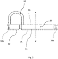
FIG. 2 is a side view of the sealing element ofFIG. 1 ; -
FIG. 3 is a bottom view of the sealing element ofFIG. 1 ; -
FIG. 4 is perspective view of the sealing element ofFIG. 1 mounted on a connection box; -
FIG. 5 is a further perspective view of the sealing element ofFIG. 1 mounted on a connection box; -
FIG. 6 is a further perspective view of the sealing element ofFIG. 1 mounted on a connection box; - For the purpose of the present invention, a cable is deemed to be any optical cable or electrical cable or hybrid cable and a connection box is deemed to be adapt to selectively receive optical cables and/or electrical cables and/or hybrid cables. Furthermore optical cables and hybrid cables can be pre-terminated with optical connectors, for example SC, LC, FC, MPO and E2000 connectors.
- Each
cable 1 has a developing axis A-A along which thecable 1 extends and enters/exits into/from theconnection box 100. It is to be noted that, upon installation, thecable 1 has afirst end portion 1a external to theconnection box 100 and a pre-terminatedsecond end portion 1b internal to theconnection box 100. Preferably, thecable 1 has connecting member or pre-terminatedconnector 3 at thesecond end portion 1b insertable and retainable into theconnection box 100. - Preferably, the
cable 1 has anexternal surface 1c defined for example by a sheath. -
Figures 4-6 show parts of aconnection box 100 able to receive and retain one ormore cables 1. - The
connection box 100 comprises aside wall 10 and one or more apertures 20 formed on theside wall 10. Preferably, each aperture 20 allows the insertion ofsecond end portion 1b of thecables 1 such that aportion 2 of eachcable 1 passing through the aperture 20 is arranged at the aperture 20. - More preferably, the
side wall 10 defines ainner volume 10a wherein one or more adapters (not shown) are arranged for receiving connectors at the pre-terminatedsecond end portion 1b of thecables 1 inserted in the aperture 20. - The
connection box 100 comprises asealing element 30 for sealing the aperture 20 of theside wall 10 of theconnection box 100. The sealingelement 30 is configured to receive theportion 2 of thecable 1 passing through the aperture 20. Thanks to the sealingelement 30, the tightness of theinner volume 10a is maintained. - According to one embodiment, the sealing
element 30 is removably attachable to theside wall 10 inside the aperture 20. - For sake of simplicity, in the following description, the sealing
element 30 is described when mounted in the relative aperture 20. In this configuration, the sealingelement 30 performs the sealing effect for thecables 1 and the aperture 20. This does not exclude the functional and technical features of the sealingelement 30 when considered alone removed from theside wall 10. - According to one embodiment, the sealing
element 30 comprises afirst body 31 and asecond body 32 as shown infigure 1 . Preferably, thefirst body 31 seals afirst portion 21 of aperture 20 and thesecond body 32 seals asecond portion 22 of the aperture 20. - Preferably, the sealing
element 30 has aninternal surface 35 facing theinner volume 10a and an opposedexternal surface 36 spaced apart along a longitudinal direction X-X. - It is to be noted that the
first body 31 and thesecond body 32 have aninternal surface external surface internal surface 35 and theexternal surface 36 of the sealingelement 30. - According to one embodiment, the sealing
element 30 has anedge portion 37 which is coupled with theside wall 10 at the aperture 20. Specifically, theedge portion 37 is defined between theinternal surface 35 and theexternal surface 36. Preferably, theedge portion 37 has agroove 38 which engages, preferably matches, with theside wall 10 allowing the sealingelement 30 to be attached to theconnection box 100 in the aperture 20. - According to one embodiment, the
groove 38 is divided between thefirst body 31 and thesecond body 32 respectively in afirst portion groove 38a and in asecond portion groove 38b. - According to an alternative embodiment, the
groove 38 is only formed on thefirst body 31. Specifically, thefirst body 31 extends at least peripherally along the entire aperture 20 so as to surround and define thesecond portion 22 of aperture 20. - According to one embodiment, the
first body 31 has one or moresealable openings 40. Eachopening 40 defines a passing throughchannel 40a extending between theinternal surface 31a and theexternal surface 31b along the longitudinal direction X-X. It is to be noted that the developing axis A-A of an insertedcable 1 in the one of theopenings 40 lies along the longitudinal direction X-X. Preferably, each opening 40 is configured to receive theportion 2 of acable 1 passing through the aperture 20 of theside wall 10. - More preferably, each opening 40 is configured to act on the
external surface 1c of thecable 1 providing a sealing effect. - According to one embodiment, the
openings 40 are adjacently arranged along one ormore rows 42 or a path, not shown, which can have different geometries such as a "S", "C" or "U" shape. - According to one embodiment, the
second portion 22 of the aperture 20 defines aninsertion area 23 configured to receive a connector at the pre-terminatedsecond end portion 1b of thecable 1. Accordingly, each opening 40 has a receivingarea 41 smaller than theinsertion area 23. Preferably, each receivingarea 41 is configured to house theportion 2 of thecable 1, namely a portion ofexternal surface 1c passing through the aperture 20 at the sealingelement 30. - The
second body 32 is movable relative to thefirst body 31 to seal and unseal thesecond portion 22 of the aperture 20 for inserting apre-terminated cable 1 in thesecond portion 22 of the aperture 20. Preferably, thesecond body 32 is configured to pass between a sealing position wherein thesecond body 32 seals thesecond portion 22 of the aperture 20, more preferably plugging in thesecond portion 22 of the aperture 20, and an unsealing position wherein thesecond body 32 allows access to thesecond portion 22 of the aperture 20 to insert acable 1. More preferably, thesecond body 32 is shaped so as to cover theinsertion area 23. - The
first body 31 has a slidingline 50 which mutually connects theopenings 40 and joins thesecond portion 22 of the aperture 20 with theopenings 40. - Specifically, the sliding
line 50 allows acable 1 passing through thesecond portion 22 of the aperture 20 to slide along the slidingline 50 between thesecond portion 22 of the aperture 20 and theopenings 40. Upon insertion of thesecond end portion 1b of thecable 1 through thesecond portion 22 of the aperture 20, when thesecond body 32 is in the unsealing position, the slidingline 50 allows thecable 1 to slide from thesecond portion 22 of the aperture 20 to one of theopenings 40. - The sliding
line 50 is also configured to allow thecable 1 to move from theopening 40 to thesecond portion 22 of aperture 20 or to anotheropening 40. - Thanks to the combination of the movable
second body 32 and the slidingline 50, the sealingelement 30 provides a better sealing effect at the aperture 20 independently of thecable 1 inserted through the aperture 20. - In fact, when the
second body 32 is moved from the sealing position to the unsealing position , the pre-terminatedsecond end portion 1b of thecable 1 can be inserted in thesecond portion 22 of the aperture 20. With this arrangement, thesecond portion 22 of the aperture 20 acts as a universal port for inserting the pre-terminatedsecond end portion 1b of thecable 1 into theconnection box 100. Accordingly, slidingline 50 simplifies the installation operation of acable 1 into theconnection box 100 providing at the same time a sealing effect at the aperture 20. - According to one embodiment, the
first body 31 comprises twoopposed flaps line 50. Preferably, theflaps cable 1 along the slidingline 50. - The
first body 31 has resilient properties such that, during the passage of thecable 1 along the slidingline 50, thefirst body 31 deforms along a deformation direction Y-Y perpendicular to the slidingline 50. - Preferably, upon sliding of the
cable 1 along the slidingline 50, thefirst body 31 is configured to be compressed between thecable 1 and theside wall 10 along the deformation direction Y-Y and to elastically deform back upon the passage of thecable 1. - More preferably, the
first body 31 is configured to pass between an uncompressed configuration and a compressed configuration around the slidingline 50 upon the sliding of thecable 1 along the slidingline 50. - More preferably, each
flap side wall 10 compressing thefirst body 31, upon passage of thecable 1 along the slidingline 50 and eachflap opposed flap cable 1 is passed. - According to one embodiment, the sealing
element 30 is made of TPV rubber preferably with a shore hardness of 30-60. - According to one embodiment, the
flaps line 50. Preferably, theflaps flaps - According to an alternative embodiment, the
connection box 100 comprises afirst plug element 70 arranged between theflaps line 50. With this embodiment, theflaps passing sliding line 50. - According to one embodiment,
first body 31 of the sealingelement 30 is a one piece body. Preferably the slidingline 50 comprises a joiningportion 50a joining thefirst body 31 with thesecond portion 22 of the aperture 20. The slidingline 50 extends between the joiningportion 50a and anopening 40 which avoids thecable 1 to slide beyond. - According to one embodiment, the
first body 31 is associated to thesecond body 32. Preferably, thefirst body 31 delimits, as a function of its dimensions and shape, thesecond portion 22 of aperture 20 and then thesecond body 32. - According to one embodiment, the sealing
element 30 comprises a connectingmember 60 connecting thefirst body 31 with thesecond body 32. The connectingmember 60 joins thefirst body 31 and thesecond body 32 extending respectively from theexternal surfaces - According to one embodiment, the
connection box 100 comprises asecond plug element 80 arranged in one ormore openings 40 and configured to seal theopenings 40. - According to an alternative embodiment, the
first plugs 70 and the second plugs 80 are connected in frangible manner such that, upon insertion of one ormore cables 1, one or more of thefirst plugs 80 and of the second plugs 70 are removed for positioning thecable 1 in one of theopenings 40. - The present invention further relates to a sealing
assembly 200 shown infigures 4-6 . The sealingassembly 200 comprises theconnection box 100 and one ormore cables 1 inserted in the aperture 20 and received in one ormore openings 40 establishing a sealing effect with theopenings 40 themselves. Specifically, eachcable 1, passing through oneopening 40, has been inserted into the aperture 20 passing through thesecond portion 22 of the aperture 20 upon movement of thesecond body 32 to unseal thesecond end portion 22. Furthermore eachcable 1, passing through oneopening 40, has been moved along the slidingline 50.
Claims (11)
- Sealing element (30) for sealing an aperture (20) of a side wall (10) of a connection box (100), said sealing element (30) being attachable to the side wall (10) inside the aperture (20) and comprising:- a first body (31) configured to seal a first portion (21) of the aperture (20) and having one or more sealable openings (40), each opening (40) being configured to receive a portion of a cable (1) passing through the aperture (20) of the side wall (10), and- a second body (32) configured to seal a second portion (22) of the aperture (20); wherein:- the second body (32) is movable relative to the first body (31) to seal and unseal the second portion (22) of the aperture (20) for inserting a cable (1) in the second portion (22) of the aperture (20);- the first body (31) has a sliding line (50) mutually connecting the openings (40) and joining the second portion (22) of the aperture (20) with the openings (40), said sliding line (50) allowing a cable (1) passing through the second portion (22) of the aperture (20) to slide along the sliding line (50) between the second portion (22) of the aperture (20) and the openings (40),- the first body (31) has resilient properties such that, during the passage of the cable (1) along the sliding line (50), the first body (31) deforms along a deformation direction (Y-Y) perpendicular to the sliding line (50).
- The sealing element (30) according to claim 1, wherein the first body (31) of the sealing element (30) is a one piece body.
- The sealing element (30) according to claim 1 or 2, wherein the first body (31) is associated to the second body (32).
- The sealing element (30) according to claim 3, wherein the sealing element (30) comprises a connecting member (60) connecting the first body (31) with the second body (32).
- The sealing element (30) according to any claims 1 to 4, wherein the first body (31) comprises two opposed flaps (33, 34) forming the sliding line (50), the flaps (33, 34) being configured to mutually space apart upon sliding of a cable (1) along the sliding line (50).
- The sealing element according to claim 5, wherein the flaps (33, 34) are arranged in a mutually faced and close relationship for sealing the sliding line (50).
- Connection box (100) for cables (1) comprising:- a side wall (10) and an aperture (20) on the side wall (10);- a sealing element (30) according to any of claims 1 to 6, the sealing element (30) being attached to the side wall (10) inside the aperture (20) for sealing the aperture (20), the sealing element (30) comprising:- a first body (31) sealing a first portion (21) of the aperture (20) and having one or more sealable openings (40), each opening (40) being configured to receive a portion of a cable (1) passing through the aperture (20) of the side wall (10), and- a second body (32) sealing a second portion (22) of the aperture (20);wherein:- the second body (32) is movable relative to the first body (31) to seal and unseal the second portion (22) of the aperture (2) for inserting a cable (1) in the second portion (22) of the aperture (20);- the first body (31) has a sliding line (50) mutually connecting the openings (40) and joining the second portion (22) of the aperture (20) with the openings (40), said sliding line (50) allowing a cable (1) passing through the second portion (22) of the aperture (20) to slide along the sliding line (50) between the second portion (22) of the aperture (20) and the openings (40);- the first body (31) has resilient properties such that, during the passage of the cable (1) along the sliding line (50), the first body (31) deforms along a deformation direction (Y-Y) perpendicular to the sliding line (50).
- The connection box (100) according to claim 7, wherein the second portion (22) of the aperture (20) defines an insertion area (23) and each opening (40) has a receiving area (41) smaller than the insertion area (23).
- The connection box (100) according to claim 7 or 8, wherein:- the first body (31) comprises two opposed flaps (33, 34) forming the sliding line (50), the flaps (33, 34) being configured to mutually space apart upon sliding of a cable (1) along the sliding line (50),- the connection box (100) comprises a first plug element (70) arranged between the flaps (33, 34) and configured to seal the sliding line (50).
- The connection box (100) according to claim 9, wherein the connection box (100) comprises a second plug element (80) arranged in one or more openings (40) and configured to seal the openings (40).
- Sealing assembly (200) comprising:- a connection box (100) according to any of claims 7-10;- one or more cables (1), each cable passing through one opening (40).
Applications Claiming Priority (1)
| Application Number | Priority Date | Filing Date | Title |
|---|---|---|---|
| IT102020000022771A IT202000022771A1 (en) | 2020-09-28 | 2020-09-28 | CONNECTION BOX FOR CABLES |
Publications (3)
| Publication Number | Publication Date |
|---|---|
| EP3975354A1 true EP3975354A1 (en) | 2022-03-30 |
| EP3975354B1 EP3975354B1 (en) | 2023-07-05 |
| EP3975354C0 EP3975354C0 (en) | 2023-07-05 |
Family
ID=73498216
Family Applications (1)
| Application Number | Title | Priority Date | Filing Date |
|---|---|---|---|
| EP21199179.9A Active EP3975354B1 (en) | 2020-09-28 | 2021-09-27 | Sealing element and connection box with said sealing element |
Country Status (5)
| Country | Link |
|---|---|
| EP (1) | EP3975354B1 (en) |
| AU (1) | AU2021240149A1 (en) |
| ES (1) | ES2960323T3 (en) |
| IT (1) | IT202000022771A1 (en) |
| PL (1) | PL3975354T3 (en) |
Citations (7)
| Publication number | Priority date | Publication date | Assignee | Title |
|---|---|---|---|---|
| US5726392A (en) | 1997-02-21 | 1998-03-10 | Communications Technology Corporation | Communications housing having grommet assembly |
| US20070227771A1 (en) | 2006-03-29 | 2007-10-04 | Franz Sterner | Gasket made of an elastomer, especially silicone |
| US20080253730A1 (en) | 2007-04-10 | 2008-10-16 | Terry Dean Cox | Grommet and plate assembly for sealing fiber optic closures |
| US7544901B2 (en) | 2004-11-02 | 2009-06-09 | Icotek Projekt Gmbh & Co. Kg | Cable duct |
| US20120142212A1 (en) * | 2009-08-31 | 2012-06-07 | Lyons Jr Thomas E | Strain relief device |
| EP3012933A2 (en) | 2014-10-22 | 2016-04-27 | Bombardier Transportation GmbH | Cable passage seal for a cable duct, construction kit for a cable passage sealing and method for mounting a cable passage seal for a cable duct |
| WO2018024286A1 (en) | 2016-08-05 | 2018-02-08 | Harting Electric Gmbh & Co. Kg | Device and method for leading cables through a wall opening |
-
2020
- 2020-09-28 IT IT102020000022771A patent/IT202000022771A1/en unknown
-
2021
- 2021-09-27 PL PL21199179.9T patent/PL3975354T3/en unknown
- 2021-09-27 ES ES21199179T patent/ES2960323T3/en active Active
- 2021-09-27 EP EP21199179.9A patent/EP3975354B1/en active Active
- 2021-09-28 AU AU2021240149A patent/AU2021240149A1/en active Pending
Patent Citations (7)
| Publication number | Priority date | Publication date | Assignee | Title |
|---|---|---|---|---|
| US5726392A (en) | 1997-02-21 | 1998-03-10 | Communications Technology Corporation | Communications housing having grommet assembly |
| US7544901B2 (en) | 2004-11-02 | 2009-06-09 | Icotek Projekt Gmbh & Co. Kg | Cable duct |
| US20070227771A1 (en) | 2006-03-29 | 2007-10-04 | Franz Sterner | Gasket made of an elastomer, especially silicone |
| US20080253730A1 (en) | 2007-04-10 | 2008-10-16 | Terry Dean Cox | Grommet and plate assembly for sealing fiber optic closures |
| US20120142212A1 (en) * | 2009-08-31 | 2012-06-07 | Lyons Jr Thomas E | Strain relief device |
| EP3012933A2 (en) | 2014-10-22 | 2016-04-27 | Bombardier Transportation GmbH | Cable passage seal for a cable duct, construction kit for a cable passage sealing and method for mounting a cable passage seal for a cable duct |
| WO2018024286A1 (en) | 2016-08-05 | 2018-02-08 | Harting Electric Gmbh & Co. Kg | Device and method for leading cables through a wall opening |
Also Published As
| Publication number | Publication date |
|---|---|
| IT202000022771A1 (en) | 2022-03-28 |
| EP3975354B1 (en) | 2023-07-05 |
| EP3975354C0 (en) | 2023-07-05 |
| PL3975354T3 (en) | 2023-12-11 |
| AU2021240149A1 (en) | 2022-04-14 |
| ES2960323T3 (en) | 2024-03-04 |
Similar Documents
| Publication | Publication Date | Title |
|---|---|---|
| US5634807A (en) | Waterproof structure of connector | |
| US7927129B2 (en) | Electrical connector having cable securing device | |
| KR0156026B1 (en) | Hooded electrical connector with terminal position assurance means | |
| US6302734B1 (en) | Waterproof connector with sealing member | |
| EP0955697B1 (en) | A waterproof connector | |
| EP3048016B1 (en) | Sealed header assembly | |
| KR102629391B1 (en) | bushing housing | |
| CN110081241A (en) | Seal insertion piece | |
| CN109565163A (en) | Device and method for guiding cable to pass through wall portion opening | |
| US12040574B2 (en) | Device for introducing cables through an opening | |
| US10910762B2 (en) | Connector | |
| US20240332842A1 (en) | Connector | |
| EP3975354B1 (en) | Sealing element and connection box with said sealing element | |
| US12074394B2 (en) | Plug connector | |
| US20250105552A1 (en) | Connector | |
| EP3700035B1 (en) | A modular distribution box for cables | |
| WO2020025134A1 (en) | Sealing unit for optical fiber cable cabinet | |
| US6132256A (en) | Design of a lambda module with mating plug | |
| US10720718B2 (en) | Branch connector and communication network | |
| CN109845049A (en) | Feed-through connector assembly and equipment having the same | |
| US20240111110A1 (en) | Seal assembly for a port of an enclosure that permits a cable terminated with a connector to be inserted into and removed from the port with the connector attached to the cable | |
| EP4290703A1 (en) | Adapter connector assembly, electrical connector plug, and electrical connector kit | |
| JP2020161443A (en) | Connector structure | |
| EP3993175A1 (en) | Sealed connector housing for an angled electrical connector | |
| US12069816B2 (en) | Power conversion device |
Legal Events
| Date | Code | Title | Description |
|---|---|---|---|
| PUAI | Public reference made under article 153(3) epc to a published international application that has entered the european phase |
Free format text: ORIGINAL CODE: 0009012 |
|
| STAA | Information on the status of an ep patent application or granted ep patent |
Free format text: STATUS: THE APPLICATION HAS BEEN PUBLISHED |
|
| AK | Designated contracting states |
Kind code of ref document: A1 Designated state(s): AL AT BE BG CH CY CZ DE DK EE ES FI FR GB GR HR HU IE IS IT LI LT LU LV MC MK MT NL NO PL PT RO RS SE SI SK SM TR |
|
| STAA | Information on the status of an ep patent application or granted ep patent |
Free format text: STATUS: REQUEST FOR EXAMINATION WAS MADE |
|
| 17P | Request for examination filed |
Effective date: 20220905 |
|
| RBV | Designated contracting states (corrected) |
Designated state(s): AL AT BE BG CH CY CZ DE DK EE ES FI FR GB GR HR HU IE IS IT LI LT LU LV MC MK MT NL NO PL PT RO RS SE SI SK SM TR |
|
| GRAP | Despatch of communication of intention to grant a patent |
Free format text: ORIGINAL CODE: EPIDOSNIGR1 |
|
| STAA | Information on the status of an ep patent application or granted ep patent |
Free format text: STATUS: GRANT OF PATENT IS INTENDED |
|
| RIC1 | Information provided on ipc code assigned before grant |
Ipc: H02G 3/32 20000101ALI20230111BHEP Ipc: H02G 3/08 19680901ALI20230111BHEP Ipc: H02B 1/30 19900101AFI20230111BHEP |
|
| INTG | Intention to grant announced |
Effective date: 20230127 |
|
| GRAS | Grant fee paid |
Free format text: ORIGINAL CODE: EPIDOSNIGR3 |
|
| GRAA | (expected) grant |
Free format text: ORIGINAL CODE: 0009210 |
|
| STAA | Information on the status of an ep patent application or granted ep patent |
Free format text: STATUS: THE PATENT HAS BEEN GRANTED |
|
| AK | Designated contracting states |
Kind code of ref document: B1 Designated state(s): AL AT BE BG CH CY CZ DE DK EE ES FI FR GB GR HR HU IE IS IT LI LT LU LV MC MK MT NL NO PL PT RO RS SE SI SK SM TR |
|
| REG | Reference to a national code |
Ref country code: CH Ref legal event code: EP |
|
| REG | Reference to a national code |
Ref country code: AT Ref legal event code: REF Ref document number: 1585702 Country of ref document: AT Kind code of ref document: T Effective date: 20230715 |
|
| REG | Reference to a national code |
Ref country code: DE Ref legal event code: R096 Ref document number: 602021003264 Country of ref document: DE |
|
| REG | Reference to a national code |
Ref country code: IE Ref legal event code: FG4D |
|
| U01 | Request for unitary effect filed |
Effective date: 20230719 |
|
| U07 | Unitary effect registered |
Designated state(s): AT BE BG DE DK EE FI FR IT LT LU LV MT NL PT SE SI Effective date: 20230726 |
|
| REG | Reference to a national code |
Ref country code: LT Ref legal event code: MG9D |
|
| U20 | Renewal fee for the european patent with unitary effect paid |
Year of fee payment: 3 Effective date: 20230927 |
|
| PG25 | Lapsed in a contracting state [announced via postgrant information from national office to epo] |
Ref country code: GR Free format text: LAPSE BECAUSE OF FAILURE TO SUBMIT A TRANSLATION OF THE DESCRIPTION OR TO PAY THE FEE WITHIN THE PRESCRIBED TIME-LIMIT Effective date: 20231006 |
|
| PG25 | Lapsed in a contracting state [announced via postgrant information from national office to epo] |
Ref country code: IS Free format text: LAPSE BECAUSE OF FAILURE TO SUBMIT A TRANSLATION OF THE DESCRIPTION OR TO PAY THE FEE WITHIN THE PRESCRIBED TIME-LIMIT Effective date: 20231105 |
|
| PG25 | Lapsed in a contracting state [announced via postgrant information from national office to epo] |
Ref country code: RS Free format text: LAPSE BECAUSE OF FAILURE TO SUBMIT A TRANSLATION OF THE DESCRIPTION OR TO PAY THE FEE WITHIN THE PRESCRIBED TIME-LIMIT Effective date: 20230705 Ref country code: NO Free format text: LAPSE BECAUSE OF FAILURE TO SUBMIT A TRANSLATION OF THE DESCRIPTION OR TO PAY THE FEE WITHIN THE PRESCRIBED TIME-LIMIT Effective date: 20231005 Ref country code: IS Free format text: LAPSE BECAUSE OF FAILURE TO SUBMIT A TRANSLATION OF THE DESCRIPTION OR TO PAY THE FEE WITHIN THE PRESCRIBED TIME-LIMIT Effective date: 20231105 Ref country code: HR Free format text: LAPSE BECAUSE OF FAILURE TO SUBMIT A TRANSLATION OF THE DESCRIPTION OR TO PAY THE FEE WITHIN THE PRESCRIBED TIME-LIMIT Effective date: 20230705 Ref country code: GR Free format text: LAPSE BECAUSE OF FAILURE TO SUBMIT A TRANSLATION OF THE DESCRIPTION OR TO PAY THE FEE WITHIN THE PRESCRIBED TIME-LIMIT Effective date: 20231006 |
|
| REG | Reference to a national code |
Ref country code: ES Ref legal event code: FG2A Ref document number: 2960323 Country of ref document: ES Kind code of ref document: T3 Effective date: 20240304 |
|
| REG | Reference to a national code |
Ref country code: DE Ref legal event code: R097 Ref document number: 602021003264 Country of ref document: DE |
|
| PG25 | Lapsed in a contracting state [announced via postgrant information from national office to epo] |
Ref country code: SM Free format text: LAPSE BECAUSE OF FAILURE TO SUBMIT A TRANSLATION OF THE DESCRIPTION OR TO PAY THE FEE WITHIN THE PRESCRIBED TIME-LIMIT Effective date: 20230705 Ref country code: RO Free format text: LAPSE BECAUSE OF FAILURE TO SUBMIT A TRANSLATION OF THE DESCRIPTION OR TO PAY THE FEE WITHIN THE PRESCRIBED TIME-LIMIT Effective date: 20230705 Ref country code: CZ Free format text: LAPSE BECAUSE OF FAILURE TO SUBMIT A TRANSLATION OF THE DESCRIPTION OR TO PAY THE FEE WITHIN THE PRESCRIBED TIME-LIMIT Effective date: 20230705 Ref country code: SK Free format text: LAPSE BECAUSE OF FAILURE TO SUBMIT A TRANSLATION OF THE DESCRIPTION OR TO PAY THE FEE WITHIN THE PRESCRIBED TIME-LIMIT Effective date: 20230705 |
|
| PLBE | No opposition filed within time limit |
Free format text: ORIGINAL CODE: 0009261 |
|
| STAA | Information on the status of an ep patent application or granted ep patent |
Free format text: STATUS: NO OPPOSITION FILED WITHIN TIME LIMIT |
|
| PG25 | Lapsed in a contracting state [announced via postgrant information from national office to epo] |
Ref country code: MC Free format text: LAPSE BECAUSE OF FAILURE TO SUBMIT A TRANSLATION OF THE DESCRIPTION OR TO PAY THE FEE WITHIN THE PRESCRIBED TIME-LIMIT Effective date: 20230705 |
|
| 26N | No opposition filed |
Effective date: 20240408 |
|
| REG | Reference to a national code |
Ref country code: IE Ref legal event code: MM4A |
|
| PG25 | Lapsed in a contracting state [announced via postgrant information from national office to epo] |
Ref country code: IE Free format text: LAPSE BECAUSE OF NON-PAYMENT OF DUE FEES Effective date: 20230927 |
|
| PG25 | Lapsed in a contracting state [announced via postgrant information from national office to epo] |
Ref country code: IE Free format text: LAPSE BECAUSE OF NON-PAYMENT OF DUE FEES Effective date: 20230927 |
|
| U20 | Renewal fee for the european patent with unitary effect paid |
Year of fee payment: 4 Effective date: 20240927 |
|
| REG | Reference to a national code |
Ref country code: CH Ref legal event code: PL |
|
| PG25 | Lapsed in a contracting state [announced via postgrant information from national office to epo] |
Ref country code: CH Free format text: LAPSE BECAUSE OF NON-PAYMENT OF DUE FEES Effective date: 20240930 |
|
| PG25 | Lapsed in a contracting state [announced via postgrant information from national office to epo] |
Ref country code: CY Free format text: LAPSE BECAUSE OF FAILURE TO SUBMIT A TRANSLATION OF THE DESCRIPTION OR TO PAY THE FEE WITHIN THE PRESCRIBED TIME-LIMIT; INVALID AB INITIO Effective date: 20210927 |
|
| PG25 | Lapsed in a contracting state [announced via postgrant information from national office to epo] |
Ref country code: HU Free format text: LAPSE BECAUSE OF FAILURE TO SUBMIT A TRANSLATION OF THE DESCRIPTION OR TO PAY THE FEE WITHIN THE PRESCRIBED TIME-LIMIT; INVALID AB INITIO Effective date: 20210927 |
|
| PGFP | Annual fee paid to national office [announced via postgrant information from national office to epo] |
Ref country code: PL Payment date: 20250909 Year of fee payment: 5 |
|
| PGFP | Annual fee paid to national office [announced via postgrant information from national office to epo] |
Ref country code: GB Payment date: 20250929 Year of fee payment: 5 |
|
| U20 | Renewal fee for the european patent with unitary effect paid |
Year of fee payment: 5 Effective date: 20250929 |
|
| PG25 | Lapsed in a contracting state [announced via postgrant information from national office to epo] |
Ref country code: TR Free format text: LAPSE BECAUSE OF FAILURE TO SUBMIT A TRANSLATION OF THE DESCRIPTION OR TO PAY THE FEE WITHIN THE PRESCRIBED TIME-LIMIT Effective date: 20230705 |
|
| PGFP | Annual fee paid to national office [announced via postgrant information from national office to epo] |
Ref country code: ES Payment date: 20251001 Year of fee payment: 5 |