EP3975323A1 - Secondary battery, device, and manufacturing method for secondary battery - Google Patents
Secondary battery, device, and manufacturing method for secondary battery Download PDFInfo
- Publication number
- EP3975323A1 EP3975323A1 EP20827993.5A EP20827993A EP3975323A1 EP 3975323 A1 EP3975323 A1 EP 3975323A1 EP 20827993 A EP20827993 A EP 20827993A EP 3975323 A1 EP3975323 A1 EP 3975323A1
- Authority
- EP
- European Patent Office
- Prior art keywords
- sealing region
- top sealing
- crease line
- secondary battery
- main body
- Prior art date
- Legal status (The legal status is an assumption and is not a legal conclusion. Google has not performed a legal analysis and makes no representation as to the accuracy of the status listed.)
- Pending
Links
- 238000004519 manufacturing process Methods 0.000 title claims abstract description 6
- 238000007789 sealing Methods 0.000 claims abstract description 275
- 238000004806 packaging method and process Methods 0.000 claims abstract description 39
- 239000012785 packaging film Substances 0.000 claims description 28
- 229920006280 packaging film Polymers 0.000 claims description 28
- 238000005452 bending Methods 0.000 claims description 19
- 238000009966 trimming Methods 0.000 claims description 12
- 238000005520 cutting process Methods 0.000 claims description 2
- 238000003466 welding Methods 0.000 claims description 2
- 239000010410 layer Substances 0.000 description 29
- 229910052751 metal Inorganic materials 0.000 description 16
- 239000002184 metal Substances 0.000 description 16
- 238000007906 compression Methods 0.000 description 11
- 230000006835 compression Effects 0.000 description 9
- 238000000034 method Methods 0.000 description 9
- 238000000465 moulding Methods 0.000 description 8
- 239000000463 material Substances 0.000 description 6
- 239000011241 protective layer Substances 0.000 description 5
- PXHVJJICTQNCMI-UHFFFAOYSA-N Nickel Chemical compound [Ni] PXHVJJICTQNCMI-UHFFFAOYSA-N 0.000 description 4
- 229910052782 aluminium Inorganic materials 0.000 description 4
- XAGFODPZIPBFFR-UHFFFAOYSA-N aluminium Chemical compound [Al] XAGFODPZIPBFFR-UHFFFAOYSA-N 0.000 description 4
- 238000010586 diagram Methods 0.000 description 4
- 239000011888 foil Substances 0.000 description 3
- RYGMFSIKBFXOCR-UHFFFAOYSA-N Copper Chemical compound [Cu] RYGMFSIKBFXOCR-UHFFFAOYSA-N 0.000 description 2
- 239000004743 Polypropylene Substances 0.000 description 2
- 229910000831 Steel Inorganic materials 0.000 description 2
- 239000000853 adhesive Substances 0.000 description 2
- 230000001070 adhesive effect Effects 0.000 description 2
- 239000011230 binding agent Substances 0.000 description 2
- 238000007599 discharging Methods 0.000 description 2
- 238000004880 explosion Methods 0.000 description 2
- 239000007773 negative electrode material Substances 0.000 description 2
- 229910052759 nickel Inorganic materials 0.000 description 2
- 229920006255 plastic film Polymers 0.000 description 2
- 239000002985 plastic film Substances 0.000 description 2
- -1 polypropylene Polymers 0.000 description 2
- 229920001155 polypropylene Polymers 0.000 description 2
- 239000007774 positive electrode material Substances 0.000 description 2
- 239000010959 steel Substances 0.000 description 2
- 238000004804 winding Methods 0.000 description 2
- OKTJSMMVPCPJKN-UHFFFAOYSA-N Carbon Chemical compound [C] OKTJSMMVPCPJKN-UHFFFAOYSA-N 0.000 description 1
- WHXSMMKQMYFTQS-UHFFFAOYSA-N Lithium Chemical compound [Li] WHXSMMKQMYFTQS-UHFFFAOYSA-N 0.000 description 1
- 239000004677 Nylon Substances 0.000 description 1
- 239000002202 Polyethylene glycol Substances 0.000 description 1
- 230000002159 abnormal effect Effects 0.000 description 1
- 230000009286 beneficial effect Effects 0.000 description 1
- 229910052802 copper Inorganic materials 0.000 description 1
- 239000010949 copper Substances 0.000 description 1
- 239000011889 copper foil Substances 0.000 description 1
- 230000007797 corrosion Effects 0.000 description 1
- 238000005260 corrosion Methods 0.000 description 1
- 238000004146 energy storage Methods 0.000 description 1
- 239000010439 graphite Substances 0.000 description 1
- 229910002804 graphite Inorganic materials 0.000 description 1
- 229910052744 lithium Inorganic materials 0.000 description 1
- GELKBWJHTRAYNV-UHFFFAOYSA-K lithium iron phosphate Chemical compound [Li+].[Fe+2].[O-]P([O-])([O-])=O GELKBWJHTRAYNV-UHFFFAOYSA-K 0.000 description 1
- LBSANEJBGMCTBH-UHFFFAOYSA-N manganate Chemical compound [O-][Mn]([O-])(=O)=O LBSANEJBGMCTBH-UHFFFAOYSA-N 0.000 description 1
- 229920001778 nylon Polymers 0.000 description 1
- 229920001223 polyethylene glycol Polymers 0.000 description 1
- 229910052710 silicon Inorganic materials 0.000 description 1
- 239000010703 silicon Substances 0.000 description 1
- KKEYFWRCBNTPAC-UHFFFAOYSA-L terephthalate(2-) Chemical compound [O-]C(=O)C1=CC=C(C([O-])=O)C=C1 KKEYFWRCBNTPAC-UHFFFAOYSA-L 0.000 description 1
Images



Classifications
-
- H—ELECTRICITY
- H01—ELECTRIC ELEMENTS
- H01M—PROCESSES OR MEANS, e.g. BATTERIES, FOR THE DIRECT CONVERSION OF CHEMICAL ENERGY INTO ELECTRICAL ENERGY
- H01M50/00—Constructional details or processes of manufacture of the non-active parts of electrochemical cells other than fuel cells, e.g. hybrid cells
- H01M50/50—Current conducting connections for cells or batteries
- H01M50/531—Electrode connections inside a battery casing
- H01M50/533—Electrode connections inside a battery casing characterised by the shape of the leads or tabs
-
- H—ELECTRICITY
- H01—ELECTRIC ELEMENTS
- H01M—PROCESSES OR MEANS, e.g. BATTERIES, FOR THE DIRECT CONVERSION OF CHEMICAL ENERGY INTO ELECTRICAL ENERGY
- H01M50/00—Constructional details or processes of manufacture of the non-active parts of electrochemical cells other than fuel cells, e.g. hybrid cells
- H01M50/10—Primary casings; Jackets or wrappings
- H01M50/102—Primary casings; Jackets or wrappings characterised by their shape or physical structure
- H01M50/105—Pouches or flexible bags
-
- H—ELECTRICITY
- H01—ELECTRIC ELEMENTS
- H01M—PROCESSES OR MEANS, e.g. BATTERIES, FOR THE DIRECT CONVERSION OF CHEMICAL ENERGY INTO ELECTRICAL ENERGY
- H01M50/00—Constructional details or processes of manufacture of the non-active parts of electrochemical cells other than fuel cells, e.g. hybrid cells
- H01M50/10—Primary casings; Jackets or wrappings
- H01M50/172—Arrangements of electric connectors penetrating the casing
- H01M50/174—Arrangements of electric connectors penetrating the casing adapted for the shape of the cells
- H01M50/178—Arrangements of electric connectors penetrating the casing adapted for the shape of the cells for pouch or flexible bag cells
-
- H—ELECTRICITY
- H01—ELECTRIC ELEMENTS
- H01M—PROCESSES OR MEANS, e.g. BATTERIES, FOR THE DIRECT CONVERSION OF CHEMICAL ENERGY INTO ELECTRICAL ENERGY
- H01M50/00—Constructional details or processes of manufacture of the non-active parts of electrochemical cells other than fuel cells, e.g. hybrid cells
- H01M50/10—Primary casings; Jackets or wrappings
- H01M50/183—Sealing members
- H01M50/184—Sealing members characterised by their shape or structure
-
- H—ELECTRICITY
- H01—ELECTRIC ELEMENTS
- H01M—PROCESSES OR MEANS, e.g. BATTERIES, FOR THE DIRECT CONVERSION OF CHEMICAL ENERGY INTO ELECTRICAL ENERGY
- H01M50/00—Constructional details or processes of manufacture of the non-active parts of electrochemical cells other than fuel cells, e.g. hybrid cells
- H01M50/10—Primary casings; Jackets or wrappings
- H01M50/183—Sealing members
- H01M50/186—Sealing members characterised by the disposition of the sealing members
-
- H—ELECTRICITY
- H01—ELECTRIC ELEMENTS
- H01M—PROCESSES OR MEANS, e.g. BATTERIES, FOR THE DIRECT CONVERSION OF CHEMICAL ENERGY INTO ELECTRICAL ENERGY
- H01M50/00—Constructional details or processes of manufacture of the non-active parts of electrochemical cells other than fuel cells, e.g. hybrid cells
- H01M50/50—Current conducting connections for cells or batteries
- H01M50/543—Terminals
- H01M50/547—Terminals characterised by the disposition of the terminals on the cells
- H01M50/548—Terminals characterised by the disposition of the terminals on the cells on opposite sides of the cell
-
- H—ELECTRICITY
- H01—ELECTRIC ELEMENTS
- H01M—PROCESSES OR MEANS, e.g. BATTERIES, FOR THE DIRECT CONVERSION OF CHEMICAL ENERGY INTO ELECTRICAL ENERGY
- H01M50/00—Constructional details or processes of manufacture of the non-active parts of electrochemical cells other than fuel cells, e.g. hybrid cells
- H01M50/50—Current conducting connections for cells or batteries
- H01M50/543—Terminals
- H01M50/552—Terminals characterised by their shape
- H01M50/553—Terminals adapted for prismatic, pouch or rectangular cells
- H01M50/557—Plate-shaped terminals
-
- Y—GENERAL TAGGING OF NEW TECHNOLOGICAL DEVELOPMENTS; GENERAL TAGGING OF CROSS-SECTIONAL TECHNOLOGIES SPANNING OVER SEVERAL SECTIONS OF THE IPC; TECHNICAL SUBJECTS COVERED BY FORMER USPC CROSS-REFERENCE ART COLLECTIONS [XRACs] AND DIGESTS
- Y02—TECHNOLOGIES OR APPLICATIONS FOR MITIGATION OR ADAPTATION AGAINST CLIMATE CHANGE
- Y02E—REDUCTION OF GREENHOUSE GAS [GHG] EMISSIONS, RELATED TO ENERGY GENERATION, TRANSMISSION OR DISTRIBUTION
- Y02E60/00—Enabling technologies; Technologies with a potential or indirect contribution to GHG emissions mitigation
- Y02E60/10—Energy storage using batteries
-
- Y—GENERAL TAGGING OF NEW TECHNOLOGICAL DEVELOPMENTS; GENERAL TAGGING OF CROSS-SECTIONAL TECHNOLOGIES SPANNING OVER SEVERAL SECTIONS OF THE IPC; TECHNICAL SUBJECTS COVERED BY FORMER USPC CROSS-REFERENCE ART COLLECTIONS [XRACs] AND DIGESTS
- Y02—TECHNOLOGIES OR APPLICATIONS FOR MITIGATION OR ADAPTATION AGAINST CLIMATE CHANGE
- Y02P—CLIMATE CHANGE MITIGATION TECHNOLOGIES IN THE PRODUCTION OR PROCESSING OF GOODS
- Y02P70/00—Climate change mitigation technologies in the production process for final industrial or consumer products
- Y02P70/50—Manufacturing or production processes characterised by the final manufactured product
Definitions
- a packaging bag made of an aluminum plastic film or a steel plastic film may be used to replace a metal housing to reduce weight of the battery and increase energy density.
- the present invention provides a secondary battery including an electrode assembly, a packaging bag and an electrode lead.
- the packaging bag has a main body portion and a sealing portion connected to the main body portion, the electrode assembly is housed in the main body portion, and the electrode lead is connected to the electrode assembly and passes through the sealing portion.
- the sealing portion includes a top sealing region and a side sealing region, the top sealing region is located on an outer side of the main body portion in a longitudinal direction, and the side sealing region is located on an outer side of the main body portion in a transverse direction.
- the top sealing region includes a first top sealing region and a second top sealing region, the electrode lead passes through the first top sealing region, the second top sealing region extends from one end of the first top sealing region closes to the side sealing region and is connected to the side sealing region, and the second top sealing region is inclined toward a side close to the electrode assembly relative to the first top sealing region.
- the side sealing region has a first crease line extending in the longitudinal direction, and the side sealing region is bent toward the main body portion along the first crease line.
- the top sealing region has a second crease line extending in the transverse direction, and the top sealing region and the electrode lead are bent along the second crease line.
- An extension line of the first crease line intersects an extension line of the second crease line, and an intersection point of the two is located on one side of the second top sealing region away from the electrode assembly.
- one end of the first top sealing region close to the electrode assembly has a first edge
- one end of the first top sealing region away from the electrode assembly has a second edge.
- the second crease line is at least partially located between the first edge and the second edge.
- one end of the second top sealing region close to the electrode assembly has a fourth edge, and the third edge and the fourth edge are parallel to each other.
- an included angle between the first edge and the fourth edge is 100°-170°.
- a width of the second top sealing region is less than or equal to a width of the first top sealing region and a width of the side sealing region.
- a surface of the second area close to the electrode assembly is bonded to the main body portion, and a surface of the second area away from the electrode assembly is bonded to the first area.
- a size of the second area is smaller than a size of the first area.
- the two insulating members 4 respectively isolate the two electrode leads 3 from the sealing portion 22.
- Each insulating member 4 surrounds an outer side of a corresponding electrode lead 3. Apart of the insulating member 4 is clamped between the two packaging films 23, thereby isolating the electrode lead 3 from the packaging films 23 and reducing a risk of contact of the electrode lead 3 with the metal layer 232.
- a material of the insulating member 4 may be polypropylene.
- FIG. 7 to FIG. 9 are different schematic diagrams of a secondary battery according to the present invention in a molding process. Molding steps of the secondary battery of the present application will be described below in detail with reference to FIG. 7 to FIG. 9 .
- the included angle ⁇ between the first edge E1 and the fourth edge E4 is 100°-170°.
- the side sealing region 222 is bonded to a surface of the main body portion 21 through an insulating adhesive, which avoids unfolding the side sealing region 222.
- the insulating adhesive may coat the exposed metal layer 232, which reduces corrosion of the metal layer 232.
Landscapes
- Chemical & Material Sciences (AREA)
- Chemical Kinetics & Catalysis (AREA)
- Electrochemistry (AREA)
- General Chemical & Material Sciences (AREA)
- Sealing Battery Cases Or Jackets (AREA)
Abstract
Description
- The present application claims priority to
Chinese Patent Application No. 201920975727.X, filed to the Chinese Patent Office on June 26, 2019 - The present invention relates to the field of batteries, and in particular, to a secondary battery, an apparatus and a manufacturing method for a secondary battery.
- With the rapid development of portable electronic devices, requirements for battery energy density are getting higher and higher. In a secondary battery, a packaging bag made of an aluminum plastic film or a steel plastic film may be used to replace a metal housing to reduce weight of the battery and increase energy density.
- An electrode assembly of the secondary battery is housed in the packaging bag, and edges of the packaging bag may be connected in a sealing manner by thermal compression to form a sealing portion. However, the sealing portion occupies larger space, which affects the energy density of the secondary battery.
- In view of the problem in the background, an objective of the present invention is to provide a secondary battery, an apparatus and a manufacturing method for a secondary battery, and the secondary battery can increase energy density and ensure sealing performance.
- To achieve the foregoing objective, the present invention provides a secondary battery including an electrode assembly, a packaging bag and an electrode lead. The packaging bag has a main body portion and a sealing portion connected to the main body portion, the electrode assembly is housed in the main body portion, and the electrode lead is connected to the electrode assembly and passes through the sealing portion. The sealing portion includes a top sealing region and a side sealing region, the top sealing region is located on an outer side of the main body portion in a longitudinal direction, and the side sealing region is located on an outer side of the main body portion in a transverse direction. The top sealing region includes a first top sealing region and a second top sealing region, the electrode lead passes through the first top sealing region, the second top sealing region extends from one end of the first top sealing region closes to the side sealing region and is connected to the side sealing region, and the second top sealing region is inclined toward a side close to the electrode assembly relative to the first top sealing region. The side sealing region has a first crease line extending in the longitudinal direction, and the side sealing region is bent toward the main body portion along the first crease line. The top sealing region has a second crease line extending in the transverse direction, and the top sealing region and the electrode lead are bent along the second crease line. An extension line of the first crease line intersects an extension line of the second crease line, and an intersection point of the two is located on one side of the second top sealing region away from the electrode assembly.
- According to the secondary battery as described above, one end of the first top sealing region close to the electrode assembly has a first edge, and one end of the first top sealing region away from the electrode assembly has a second edge. The second crease line is at least partially located between the first edge and the second edge.
- According to the secondary battery as described above, one end of the second top sealing region away from the electrode assembly has a third edge. The first crease line runs through the side sealing region in the longitudinal direction, and the first crease line intersects the third edge to form a first intersection point. The second crease line runs through the first top sealing region, and the second crease line intersects the third edge to form a second intersection point. A distance between the first intersection point and the second intersection point is greater than 1 mm.
- According to the secondary battery as described above, one end of the second top sealing region close to the electrode assembly has a fourth edge, and the third edge and the fourth edge are parallel to each other.
- According to the secondary battery as described above, an included angle between the first edge and the fourth edge is 100°-170°.
- According to the secondary battery as described above, a width of the second top sealing region is less than or equal to a width of the first top sealing region and a width of the side sealing region.
- According to the secondary battery as described above, the side sealing region includes a first area and a second area, the first area extends from the main body portion and is bent along the first crease line, and the second area extends from an end part of the first area away from the main body portion and is folded back between the first area and the main body portion.
- According to the secondary battery as described above, in the transverse direction, a surface of the second area close to the electrode assembly is bonded to the main body portion, and a surface of the second area away from the electrode assembly is bonded to the first area.
- According to the secondary battery as described above, in the longitudinal direction, a size of the second area is smaller than a size of the first area.
- According to the secondary battery as described above, the secondary battery further includes an insulating member, and the insulating member surrounds an outer side of the electrode lead and isolates the first top sealing region from the electrode lead. In the transverse direction, the second top sealing region is located on an outer side of the insulating member.
- The present invention provides an apparatus including the secondary battery as described above.
- The present invention further provides a manufacturing method for a secondary battery including:
- providing a battery assembly and an electrode lead, and assembling the battery assembly and the electrode lead together;
- providing a packaging bag having two packaging films arranged up and down in a thickness direction, and placing the battery assembly and the electrode lead assembled together between the two packaging films;
- welding edges of the two packaging films, and cutting off four corners of the packaging bag along a trimming line, where the packaging bag has a main body portion and a sealing portion connected to the main body portion, an electrode assembly is housed in the main body portion, and the electrode lead is connected to the electrode assembly and passes through the sealing portion; the sealing portion includes a top sealing region and a side sealing region, the top sealing region is located on an outer side of the main body portion in a longitudinal direction, and the side sealing region is located on an outer side of the main body portion in a transverse direction; and the top sealing region includes a first top sealing region and a second top sealing region, the electrode lead passes through the first top sealing region, the second top sealing region extends from one end of the first top sealing region closes to the side sealing region and is connected to the side sealing region, and the second top sealing region is inclined toward a side close to the electrode assembly relative to the first top sealing region;
- providing a first crease line extending in the longitudinal direction, and bending the side sealing region along the first crease line; and
-
-
FIG. 1 is a schematic diagram of a secondary battery according to the present invention; -
FIG. 2 is a sectional view ofFIG. 1 taken along a line A-A; -
FIG. 3 is a sectional view ofFIG. 1 taken along a line B-B; -
FIG. 4 is an enlarged view ofFIG. 1 in a circle; -
FIG. 5 is a schematic diagram of a packaging film of a packaging bag ofFIG. 3 ; -
FIG. 6 is a sectional view of the packaging film ofFIG. 5 ; -
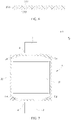
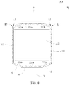
FIG. 7 to FIG. 9 are different schematic diagrams of a secondary battery according to the present invention in a molding process. - Reference signs are explained as follows:
1: electrode assembly; L1: first crease line; 2: packaging bag; L2: second crease line; 21: main body portion; L3: third crease line; 22: sealing portion; L4: trimming line; 221: top sealing region; E1: first edge; 221a: first top sealing region; E2: second edge; 221b: second top sealing region; E3: third edge; 222: side sealing region; E4: fourth edge; 222a: first area; G: notch; 222b: second area; X: longitudinal direction; 23: packaging film; Y: transverse direction; 231: protective layer; Z: thickness direction; 232: metal layer; 233: connecting layer; 3: electrode lead; and 4: insulating member. - To make the objectives, technical solutions, and advantages of the present application clearer and more comprehensible, the present application will be further described below in detail with reference to the accompanying drawings and embodiments. It should be understood that the specific embodiments described herein are merely used to explain the present application, but are not intended to limit the present application.
- In the description of the present application, unless otherwise specified and limited explicitly, the terms "first", "second", "third" and "fourth" are merely intended for a purpose of description, and shall not be understood as an indication or implication of relative importance. The term "a plurality of' refers to more than two (including two). Unless otherwise specified or illustrated, the term "connection" should be understood broadly, for example, the "connection" may either be a fixed connection, or a detachable connection, or an integrated connection, or an electrical connection, or a signal connection; and the "connection" may either be a direct connection, or an indirect connection through an intermediary. Those of ordinary skill in the art may appreciate the specific meanings of the foregoing terms in the present application according to specific conditions.
- In the description of the specification, it should be understood that the terms representing directions such as "up" and "down" described in the embodiments of the present application are described from the angles shown in the accompanying drawings, and should not be understood as limitation on the embodiments of the present application. The present application will be further described below in detail through the specific embodiments with reference to the accompanying drawings.
- With reference to
FIG. 1 to FIG. 3 , a secondary battery of the present application includes anelectrode assembly 1, apackaging bag 2, anelectrode lead 3 and aninsulating member 4. - The
electrode assembly 1 is a core member of the secondary battery for achieving charging and discharging functions. Theelectrode assembly 1 includes a positive electrode sheet, a negative electrode sheet and a diaphragm, and the diaphragm isolates the positive electrode sheet from the negative electrode sheet. The positive electrode sheet includes a positive electrode current collector and a positive active material layer coated on a surface of the positive electrode current collector, the positive electrode current collector may be aluminum foil, and the positive active material layer includes a ternary material, lithium manganate oxide or lithium iron phosphate. The negative electrode sheet includes a negative electrode current collector and a negative active material layer coated on a surface of the negative electrode current collector, the negative electrode current collector may be copper foil, and the negative active material layer includes graphite or silicon. - The
electrode assembly 1 may be in a winding structure. Specifically, there is one positive electrode sheet and one negative electrode sheet, and the positive electrode sheet and the negative electrode sheet are in banded structures. The positive electrode sheet, the diaphragm and the negative electrode sheet are stacked in sequence and wound more than two turns to form theelectrode assembly 1. When theelectrode assembly 1 is produced, theelectrode assembly 1 may be wound into a hollow cylindrical structure first, and then flattened into a flat shape after the winding. - Alternatively, the
electrode assembly 1 may also be in a laminated structure. Specifically, the positive electrode sheet is set in plurality, the negative electrode sheet is set in plurality, the plurality of positive electrode sheets and the plurality of negative electrode sheets are stacked alternately in a thickness direction Z, and the diaphragm isolates the positive electrode sheet from the negative electrode sheet. - The
packaging bag 2 includes twopackaging films 23, and the twopackaging films 23 are arranged up and down in the thickness direction Z. With reference toFIG. 5 , at least onepackaging film 23 is stamped to form a concave chamber, and theelectrode assembly 1 is located between the twopackaging films 23 and housed in the concave chamber. - With reference to
FIG. 6 , eachpackaging film 23 includes aprotective layer 231, ametal layer 232 and a connectinglayer 233, and theprotective layer 231 and the connectinglayer 233 are respectively disposed on two sides of themetal layer 232. Specifically, theprotective layer 231 may be fixed to a surface of themetal layer 232 away from theelectrode assembly 1 through a binder, and the connectinglayer 233 may be fixed to a surface of themetal layer 232 close to theelectrode assembly 1 through the binder. - A material of the
protective layer 231 may be nylon or polyethylene glycol terephthalate, a material of themetal layer 232 may be aluminum foil or steel foil, and a material of the connectinglayer 233 may be polypropylene. - By thermal compression, connecting
layers 233 of the twopackaging films 23 are directly or indirectly connected together, thereby forming a sealedpackaging bag 2. In terms of appearance, thepackaging bag 2 has amain body portion 21 and a sealingportion 22 connected to themain body portion 21, and theelectrode assembly 1 is housed in themain body portion 21. In themain body portion 21, the twopackaging films 23 are in a separated state and enclose space for housing theelectrode assembly 1. In the sealingportion 22, the connectinglayers 233 of the twopackaging films 23 are welded into one body. In the thermal compression process, the connectinglayers 233 are melted and compressed. Therefore, after the molding by the thermal compression, a thickness of the sealingportion 22 is less than a sum of thicknesses of the twopackaging films 23 before the thermal compression. - With reference to
FIG. 3 , theelectrode lead 3 is connected to theelectrode assembly 1, passes through the sealingportion 22 and extends to an outside of thepackaging bag 2. Specifically, there may be two electrode leads 3, oneelectrode lead 3 is connected to the positive electrode current collector of the positive electrode sheet, and theother electrode lead 3 is connected to the negative electrode current collector of the negative electrode sheet. The two electrode leads 3 connect theelectrode assembly 1 and other members outside thepackaging bag 2, and then charging and discharging of theelectrode assembly 1 are achieved. A material of theelectrode lead 3 may be aluminum, nickel or copper plated with nickel. - The
electrode lead 3 passes between the twopackaging films 23. Since the connectinglayer 233 is thin, theelectrode lead 3 is easily in contact with themetal layer 232, causing safety risks. Therefore, the secondary battery of the present application is preferably provided with an insulatingmember 4. - There may be two insulating
members 4. The twoinsulating members 4 respectively isolate the two electrode leads 3 from the sealingportion 22. Each insulatingmember 4 surrounds an outer side of acorresponding electrode lead 3. Apart of the insulatingmember 4 is clamped between the twopackaging films 23, thereby isolating theelectrode lead 3 from thepackaging films 23 and reducing a risk of contact of theelectrode lead 3 with themetal layer 232. A material of the insulatingmember 4 may be polypropylene. - Since a part of the insulating
member 4 is clamped between the twopackaging films 23, when thermal compression is performed on the twopackaging films 23, the connectinglayers 233 of the twopackaging films 23 are welded to the insulatingmember 4. - With reference to
FIG. 1 andFIG. 8 , the sealingportion 22 includes atop sealing region 221 and aside sealing region 222, thetop sealing region 221 is located on an outer side of themain body portion 21 in a longitudinal direction X, and theside sealing region 222 is located on an outer side of themain body portion 21 in a transverse direction Y - In an embodiment, two electrode leads 3 may respectively extend from two ends of the
packaging bag 2 in the longitudinal direction X. In this case, there may be twotop sealing regions 221, the twotop sealing regions 221 are respectively disposed on two sides of themain body portion 21 in the longitudinal direction X, and eachelectrode lead 3 respectively passes through a correspondingtop sealing region 221. In an alternative embodiment, two electrode leads 3 may extend from the same end of thepackaging bag 2 in the longitudinal direction X. In this case, there may be onetop sealing region 221, thetop seating region 221 is disposed on one side of themain body portion 21 in the longitudinal direction X, and the two electrode leads 3 both pass through the onetop sealing region 221. - There may be two
side sealing regions 222, and the twoside sealing regions 222 are respectively located on outer sides of themain body portion 21 in the transverse direction Y. With reference toFIG. 8 , in an embodiment, twotop sealing regions 221 and twoside sealing regions 222 are connected together to form an annular structure, and then sealing of thepackaging bag 2 is achieved. - The
top sealing region 221 includes a firsttop sealing region 221a and a secondtop sealing region 221b, theelectrode lead 3 passes through the firsttop sealing region 221a, the secondtop sealing region 221b extends from one end of the firsttop sealing region 221a closes to theside sealing region 222 and is connected to theside sealing region 222, and the secondtop sealing region 221b is inclined toward a side close to theelectrode assembly 1 relative to the firsttop sealing region 221a. - One end of the second
top sealing region 221b is connected to the firsttop sealing region 221a, and the other end is connected to theside sealing region 222. When the secondtop sealing region 221b is disposed obliquely relative to the firs top sealingregion 221a, spacing between the firsttop sealing region 221a and theside sealing region 222 in the longitudinal direction X can be increased. - With reference to
FIG. 8 , after the molding by the thermal compression, the sealingportion 22 has a certain width, which results in larger sizes of the secondary battery in the longitudinal direction X and the transverse direction Y, and affects energy density of the secondary battery. Therefore, optionally, with reference toFIG. 2 andFIG. 8 , according to the present application, theside sealing portion 222 is bent preferably toward themain body portion 21 to reduce a size of theside sealing region 222 in the transverse direction Y After the molding by the bending, a first crease line L1 extending in the longitudinal direction X is formed on theside sealing region 222; that is, theside sealing region 222 is bent toward themain body portion 21 along the first crease line L1. - Similarly, according to the present application, the
top sealing region 221 is further bent to reduce a size of thetop sealing region 221 in the longitudinal direction X. After the molding by the bending, a second crease line L2 extending in the transverse direction Y is formed on thetop sealing region 221; that is, thetop sealing region 221 is bent along the second crease line L2. In addition, since theelectrode lead 3 passes through thetop sealing region 221, when thetop sealing region 221 is bent along the second crease line L2, theelectrode lead 3 is also bent along the second crease line L2. - According to the present application, by bending the
top sealing region 221, a size occupied by thetop sealing region 221 and theelectrode lead 3 in the longitudinal direction X can be reduced. In addition, when a plurality of secondary batteries are connected into a group, thebent electrode lead 3 facilitates an electrical connection of adjacent batteries. - In the transverse direction Y, the second crease line L2 is located between first crease lines L1 of two
side sealing regions 222, and a size of the second crease line L2 is smaller than spacing between the two first crease lines L1. With reference toFIG. 8 andFIG. 9 , an extension line of the first crease line L1 intersects an extension line of the second crease line L2, and an intersection point of the two is located on one side of the secondtop sealing region 221b away from theelectrode assembly 1. Further, the intersection point of the extension line of the first crease line L1 and the extension line of the second crease line L2 is located on the outside of thepackaging bag 2. - If the first crease line L1 directly intersects the second crease line L2, when the
side sealing region 222 and thetop sealing region 221 are bent, thetop sealing region 221 and theside sealing region 222 easily interfere with each other. Meanwhile, there is an overlap area between thetop sealing region 221 and theside sealing region 222, and the overlap area is easily damaged in the bending process, which affects sealing performance of the packaging bag. - In the present application, by obliquely disposing the second
top sealing region 221b, the size of the overalltop sealing region 221 in the longitudinal direction X is increased, which provides more choices to the position of the second crease line L2. Meanwhile, by obliquely disposing the secondtop sealing region 221b, the size of the second crease line L2 in the transverse direction Y can also be reduced, which avoids direct intersection of the first crease line L1 and the second crease line L2. - In summary, according to the present application, by bending the
top sealing region 221 and theside sealing region 222, space occupied by the secondary battery is reduced, and energy density of the secondary battery is increased. Meanwhile, by obliquely disposing the secondtop sealing region 221b, interference between thetop sealing region 221 and theside sealing region 222 is avoided in the bending process, and sealing performance of thepackaging bag 2 is ensured. -
FIG. 7 to FIG. 9 are different schematic diagrams of a secondary battery according to the present invention in a molding process. Molding steps of the secondary battery of the present application will be described below in detail with reference toFIG. 7 to FIG. 9 . - (i)
Two packaging films 23 as described inFIG. 5 are produced by stamping, and then anelectrode assembly 1 is placed between the twopackaging films 23. It is added here that theelectrode assembly 1, anelectrode lead 3 and an insulatingmember 4 have been assembled together in advance. - (ii) By thermal compression, the two
packaging films 23 are welded at edges to form a sealingportion 22. After the thermal compression, a secondary battery as shown inFIG. 7 is formed. It should be noted that a thermal compression device may use a specially-made shape so that the sealingportion 22 located near a corner of thepackaging bag 2 has a variable width. Preferably, the sealingportion 22 located near the corner of thepackaging bag 2 is trapezoidal. - (iii) With reference to
FIG. 7 , four corners of thepackaging bag 2 are cut off along trimming lines L4 to form a secondary battery as shown inFIG. 8 . The parts cut off are preferably triangular. After the trimming, an inclined secondtop sealing region 221b and aside sealing region 222 and a firsttop sealing region 221a connecting to the secondtop sealing region 221b are formed in the sealingportion 21, and an outer side of the secondtop sealing region 221b is a notch G left after the trimming. - (iv) With reference to
FIG. 8 , theside sealing region 222 is bent along a first crease line L1. By bending theside sealing region 222, space occupied by theside sealing region 222 in a transverse direction Y can be reduced, and energy density of the secondary battery is increased. - (v) With reference to
FIG. 9 , thetop sealing region 221 is bent along a second crease line L2 to form a secondary battery as shown inFIG. 1 . By bending thetop sealing region 221, space occupied by thetop sealing region 221 and theelectrode lead 3 in a longitudinal direction X can be reduced, and the energy density of the secondary battery is increased. - According to the present application, the inclined second
top sealing region 221b and the notch G corresponding to the secondtop sealing region 221b are produced by the thermal compression process in step (ii) and the trimming process in step (iii), and then interference between thetop sealing region 221 and theside sealing region 222 is avoided in the bending process. - With reference to
FIG. 9 , one end of the firsttop sealing region 221a close to theelectrode assembly 1 has a first edge E1, and one end of the firsttop sealing region 221a away from theelectrode assembly 1 has a second edge E2. In a plane perpendicular to a thickness direction Z, a projection of the first edge E1 and a projection of the second edge E2 are approximately straight lines parallel to the transverse direction Y. The second crease line L2 is at least partially located between the first edge E1 and the second edge E2. - After the
top sealing region 221 is bent, a part of the second crease line L2 is located in the firsttop sealing region 221a, and the other part of the second crease line L2 is located in the secondtop sealing region 221b. In other words, the firsttop sealing region 221a is bent into two parts along the second crease line L2, and the secondtop sealing region 221b is bent into two parts along the second crease line L2. In this case, according to the present application, it can be avoided that other parts of thepackaging bag 2 are bent with the bending of thetop sealing region 221. - With reference to
FIG. 4 , one end of the secondtop sealing region 221b away from theelectrode assembly 1 has a third edge E3. An outer side of the third edge E3 is a notch G. With reference toFIG. 8 , the first crease line L1 runs through theside sealing region 222 in the longitudinal direction X, that is, two ends of the first crease line L1 in the longitudinal direction X respectively intersect two edges of theside sealing region 222 in the longitudinal direction X. With reference toFIG. 9 , the second crease line L2 runs through the firsttop sealing region 221a. - The first crease line L1 intersects the third edge E3 to form a first intersection point PI, the second crease line L2 intersects the third edge E3 to form a second intersection point P2, and a distance between the first intersection point P1 and the second intersection point P2 is greater than 1 mm. If the distance between the first intersection point P1 and the second intersection point P2 is too small, it will result in stress concentration at the third edge E3, and the second
top sealing region 221b is easily damaged, which affects sealing performance of thepackaging bag 2. - One end of the second
top sealing region 221b close to theelectrode assembly 1 has a fourth edge E4, and the third edge E3 and the fourth edge E4 are parallel to each other. The third edge E3 and the fourth edge E4 are arranged in parallel so that a width of the secondtop sealing region 221b is uniform, and uniformity of sealing strength of the secondtop sealing region 221b is improved. - With reference to
FIG. 4 , an included angle between the first edge E1 and the fourth edge E4 is α. When the position and the size of the first edge E1 are constant, the smaller a value of α is, and the closer the fourth edge E4 is to amain body portion 21 and theelectrode assembly 1. If the fourth edge E4 is too close to theelectrode assembly 1, the secondtop sealing region 221b with high hardness may damage theelectrode assembly 1 when the battery vibrates. The greater the value of α is, the smaller a degree of inclination of the secondtop sealing region 221b is, the smaller spacing between the first crease line L1 and the second crease line L2 in the longitudinal direction X is, and the higher a risk of interference between thetop sealing region 221 and theside sealing region 222 in bending is. Therefore, preferably, the included angle α between the first edge E1 and the fourth edge E4 is 100°-170°. - A width of the second
top sealing region 221b is less than or equal to a width of the firsttop sealing region 221a and a width of theside sealing region 222. With reference toFIG. 8 , the width of the secondtop sealing region 221b, the width of the firsttop sealing region 221a and the width of theside sealing region 222 all refer to their widths before the bending, or their widths in an unfolded state. The width of the secondtop sealing region 221b is its size in the longitudinal direction X, the width of the firsttop sealing region 221a is its size in the longitudinal direction X, and the width of theside sealing region 222 is its size in the transverse direction Y. - When the secondary battery is abnormal (for example, a short circuit), the
electrode assembly 1 releases a large amount of gas, and the gas collects in thepackaging bag 2 and causes an explosion risk. On the premise of satisfying sealing strength, the secondtop sealing region 221b may have a relatively small width. When theelectrode assembly 1 releases a large amount of gas, the gas can break through the secondtop sealing region 221b, thereby releasing the gas to the outside of thepackaging bag 2 in time, reducing the explosion risk, and improving safety performance. - With reference to
FIG. 2 andFIG. 8 , theside sealing region 222 includes afirst area 222a and asecond area 222b, thefirst area 222a extends from themain body portion 21 and is bent along the first crease line L1, and thesecond area 222b extends from an end part of thefirst area 222a away from themain body portion 21 and is folded back between thefirst area 222a and themain body portion 21. Specifically, in step (iv), theside sealing region 222 may be bent along a third crease line L3 first, thefirst area 222a and thesecond area 222b are on two sides of the third crease line L3, and then thefirst area 222a is bent along the first crease line L1. - A trimming process needs to be performed on the
packaging film 22 in the molding process, and ametal layer 232 is exposed at a cut section. The exposedmetal layer 232 is easily corroded and may cause a risk of a short circuit. According to the present application, by bending theside sealing region 222 twice, a part of themetal layer 232 may be clamped between thefirst area 222a and themain body portion 21, exposure of themetal layer 232 is reduced, and the risk of the short circuit is reduced. - With reference to
FIG. 2 , in the transverse direction Y, a surface of thesecond area 222b close to theelectrode assembly 1 is bonded to themain body portion 21, and a surface of thesecond area 222b away from theelectrode assembly 1 is bonded to thefirst area 222a. According to the present application, theside sealing region 222 is bonded to a surface of themain body portion 21 through an insulating adhesive, which avoids unfolding theside sealing region 222. In addition, the insulating adhesive may coat the exposedmetal layer 232, which reduces corrosion of themetal layer 232. - In step (iii), the notch G formed by the trimming is preferably triangular. Therefore, with reference to
FIG. 2 andFIG. 8 , in the longitudinal direction X, a size of thesecond area 222b is smaller than a size of thefirst area 222a. Since the size of thefirst area 222a is larger than the size of thesecond area 222b, thefirst area 222a may completely cover thesecond area 222b from the outer side, thereby reducing the exposure of themetal layer 232. - The
electrode lead 3 passes through the first top sealing region 2221a, and the insulatingmember 4 can isolate the firsttop sealing region 221a from theelectrode lead 3. Preferably, in the transverse direction Y, the secondtop sealing region 221b is located on an outer side of the insulatingmember 4; that is, in the thickness direction Z, the insulatingmember 4 does not overlap the secondtop sealing region 221b. With reference toFIG. 7 andFIG. 8 , according to the present application, the secondtop sealing region 221b is formed by trimming thepackaging bag 2 along the trimming line L4. If the insulatingmember 4 overlaps the secondtop sealing region 221b in the thickness direction Z, a part of the insulatingmember 4 is cut off in trimming, which affects connection strength of the insulatingmember 4 and thepackaging bag 2. - An embodiment of the present invention further provides an apparatus including the secondary battery in the foregoing embodiments, where the apparatus may be a vehicle or an energy storage device.
Claims (12)
- A secondary battery, comprising an electrode assembly (1), a packaging bag (2) and an electrode lead (3);wherein the packaging bag (2) has a main body portion (21) and a sealing portion (22) connected to the main body portion (21), the electrode assembly (1) is housed in the main body portion (21), and the electrode lead (3) is connected to the electrode assembly (1) and passes through the sealing portion (22);the sealing portion (22) comprises a top sealing region (221) and a side sealing region (222), the top sealing region (221) is located on an outer side of the main body portion (21) in a longitudinal direction (X), and the side sealing region (222) is located on an outer side of the main body portion (21) in a transverse direction (Y);the top sealing region (221) comprises a first top sealing region (221a) and a second top sealing region (221b), the electrode lead (3) passes through the first top sealing region (221a), the second top sealing region (221b) extends from one end of the first top sealing region (221a) closes to the side sealing region (222) and is connected to the side sealing region (222), and the second top sealing region (221b) is inclined toward a side close to the electrode assembly (1) relative to the first top sealing region (221a);the side sealing region (222) has a first crease line (L1) extending in the longitudinal direction (X), and the side sealing region (222) is bent toward the main body portion (21) along the first crease line (L1); the top sealing region (221) has a second crease line (L2) extending in the transverse direction (Y), and the top sealing region (221) and the electrode lead (3) are bent along the second crease line (L2); andan extension line of the first crease line (L1) intersects an extension line of the second crease line (L2), and an intersection point of the two is located on one side of the second top sealing region (221b) away from the electrode assembly (1).
- The secondary battery according to claim 1, whereinone end of the first top sealing region (221a) close to the electrode assembly (1) has a first edge (E1), and one end of the first top sealing region (221a) away from the electrode assembly (1) has a second edge (E2); andthe second crease line (L2) is at least partially located between the first edge (E1) and the second edge (E2).
- The secondary battery according to claim 1 or 2, whereinone end of the second top sealing region (221b) away from the electrode assembly (1) has a third edge (E3);the first crease line (L1) runs through the side sealing region (222) in the longitudinal direction (X), and the first crease line (L1) intersects the third edge (E3) to form a first intersection point (PI);the second crease line (L2) runs through the first top sealing region (221a), and the second crease line (L2) intersects the third edge (E3) to form a second intersection point (P2); anda distance between the first intersection point (PI) and the second intersection point (P2) is greater than 1 mm.
- The secondary battery according to claim 3, wherein one end of the second top sealing region (221b) close to the electrode assembly (1) has a fourth edge (E4), and the third edge (E3) and the fourth edge (E4) are parallel to each other.
- The secondary battery according to claim 4, wherein an included angle between the first edge (E1) and the fourth edge (E4) is 100°-170°.
- The secondary battery according to any one of claims 1 to 5, wherein a width of the second top sealing region (221b) is less than or equal to a width of the first top sealing region (221a) and a width of the side sealing region (222).
- The secondary battery according to any one of claims 1 to 6, wherein
the side sealing region (222) comprises a first area (222a) and a second area (222b), the first area (222a) extends from the main body portion (21) and is bent along the first crease line (L1), and the second area (222b) extends from an end part of the first area (222a) away from the main body portion (21) and is folded back between the first area (222a) and the main body portion (21). - The secondary battery according to claim 7, wherein in the transverse direction (Y), a surface of the second area (222b) close to the electrode assembly (1) is bonded to the main body portion (21), and a surface of the second area (222b) away from the electrode assembly (1) is bonded to the first area (222a).
- The secondary battery according to any one of claims 7 to 8, wherein in the longitudinal direction (X), a size of the second area (222b) is smaller than a size of the first area (222a).
- The secondary battery according to any one of claims 1 to 9, whereinthe secondary battery further comprises an insulating member (4), and the insulating member (4) surrounds an outer side of the electrode lead (3) and isolates the first top sealing region (221a) from the electrode lead (3); andin the transverse direction (Y), the second top sealing region (221b) is located on an outer side of the insulating member (4).
- An apparatus, comprising the secondary battery according to any one of claims 1 to 10.
- A manufacturing method for a secondary battery, comprising:providing a battery assembly (1) and an electrode lead (3), and assembling the battery assembly (1) and the electrode lead (3) together;providing a packaging bag (2) having two packaging films (23) arranged up and down in a thickness direction (Z), and placing the battery assembly (1) and the electrode lead (3) assembled together between the two packaging films (23);welding edges of the two packaging films (23), and cutting off four corners of the packaging bag (2) along a trimming line (L4), wherein the packaging bag (2) has a main body portion (21) and a sealing portion (22) connected to the main body portion (21), an electrode assembly (1) is housed in the main body portion (21), and the electrode lead (3) is connected to the electrode assembly (1) and passes through the sealing portion (22); the sealing portion (22) comprises a top sealing region (221) and a side sealing region (222), the top sealing region (221) is located on an outer side of the main body portion (21) in a longitudinal direction (X), and the side sealing region (222) is located on an outer side of the main body portion (21) in a transverse direction (Y); and the top sealing region (221) comprises a first top sealing region (221a) and a second top sealing region (221b), the electrode lead (3) passes through the first top sealing region (221a), the second top sealing region (221b) extends from one end of the first top sealing region (221a) closes to the side sealing region (222) and is connected to the side sealing region (222), and the second top sealing region (221b) is inclined toward a side close to the electrode assembly (1) relative to the first top sealing region (221a);providing a first crease line (L1) extending in the longitudinal direction (X), and bending the side sealing region (222) along the first crease line (L1); andproviding a second crease line (L2) extending in the transverse direction (Y), and bending the top sealing region (221) and the electrode lead (3) along the second crease line (L2), wherein an extension line of the first crease line (L1) intersects an extension line of the second crease line (L2), and an intersection point of the two is located on one side of the second top sealing region (221b) away from the electrode assembly (1).
Applications Claiming Priority (2)
| Application Number | Priority Date | Filing Date | Title |
|---|---|---|---|
| CN201920975727.XU CN209785987U (en) | 2019-06-26 | 2019-06-26 | Secondary battery |
| PCT/CN2020/086843 WO2020259048A1 (en) | 2019-06-26 | 2020-04-24 | Secondary battery, device, and manufacturing method for secondary battery |
Publications (2)
| Publication Number | Publication Date |
|---|---|
| EP3975323A1 true EP3975323A1 (en) | 2022-03-30 |
| EP3975323A4 EP3975323A4 (en) | 2023-07-19 |
Family
ID=68789135
Family Applications (1)
| Application Number | Title | Priority Date | Filing Date |
|---|---|---|---|
| EP20827993.5A Pending EP3975323A4 (en) | 2019-06-26 | 2020-04-24 | SECONDARY BATTERY, DEVICE AND METHOD OF MANUFACTURE FOR A SECONDARY BATTERY |
Country Status (4)
| Country | Link |
|---|---|
| US (1) | US20210126325A1 (en) |
| EP (1) | EP3975323A4 (en) |
| CN (1) | CN209785987U (en) |
| WO (1) | WO2020259048A1 (en) |
Families Citing this family (10)
| Publication number | Priority date | Publication date | Assignee | Title |
|---|---|---|---|---|
| CN209785987U (en) * | 2019-06-26 | 2019-12-13 | 宁德时代新能源科技股份有限公司 | Secondary battery |
| WO2021158070A1 (en) * | 2020-02-07 | 2021-08-12 | 주식회사 엘지에너지솔루션 | Pouch-type secondary battery and battery module |
| CN112510242B (en) * | 2020-11-30 | 2022-04-12 | 东莞新能德科技有限公司 | Secondary battery and terminal device |
| CN113904035B (en) * | 2021-09-15 | 2024-08-02 | 东莞新能安科技有限公司 | Electric core, battery module and electric equipment |
| KR102904725B1 (en) * | 2021-10-06 | 2025-12-24 | 주식회사 엘지에너지솔루션 | Pouch sealing method for pouch-type secondary battery and main sealing tool used in the same |
| CN114188597B (en) * | 2021-11-25 | 2024-11-15 | 宁德新能源科技有限公司 | Electrochemical devices, battery modules and electrical equipment |
| CN115552700A (en) * | 2021-11-30 | 2022-12-30 | 宁德新能源科技有限公司 | Batteries and electrical equipment |
| CN114614169B (en) * | 2022-03-30 | 2023-09-19 | 东莞新能源科技有限公司 | Electrochemical device, preparation method thereof and electronic device |
| CN220627729U (en) | 2022-06-27 | 2024-03-19 | 米沃奇电动工具公司 | Fuses and devices including conductive paths for the passage of electric current |
| WO2026091001A1 (en) * | 2024-10-31 | 2026-05-07 | 东莞新能源科技有限公司 | Electrochemical device and preparation method therefor, and electronic device |
Family Cites Families (13)
| Publication number | Priority date | Publication date | Assignee | Title |
|---|---|---|---|---|
| US6482544B1 (en) * | 2000-06-30 | 2002-11-19 | Mitsubishi Denki Kabushiki Kaisha | Battery package |
| JP2002319375A (en) * | 2001-04-19 | 2002-10-31 | Yuasa Corp | Sealed battery |
| US6673488B2 (en) * | 2001-07-23 | 2004-01-06 | Ngk Spark Plug Co., Ltd. | Packaging for polymer electrolytic cell and method of forming same |
| KR100553753B1 (en) * | 2003-10-16 | 2006-02-20 | 삼성에스디아이 주식회사 | Pouch Type Secondary Battery |
| CN102969533A (en) * | 2012-07-10 | 2013-03-13 | 东莞新能源科技有限公司 | Folded structure of soft pack lithium-ion battery and manufacturing method thereof |
| KR20140144843A (en) * | 2013-06-12 | 2014-12-22 | 주식회사 엘지화학 | Process for Preparation of Pouch-typed Battery Cell having Sealing Part Insulated with Curing Material |
| KR102211525B1 (en) * | 2014-06-17 | 2021-02-02 | 삼성에스디아이 주식회사 | Rechargeable battery having coner folding part |
| KR102645178B1 (en) * | 2016-01-05 | 2024-03-06 | 에스케이온 주식회사 | Secondary battery |
| CN206250224U (en) * | 2016-11-18 | 2017-06-13 | 宁德新能源科技有限公司 | Battery core encapsulating structure |
| KR102576167B1 (en) * | 2016-12-20 | 2023-09-07 | 에스케이온 주식회사 | Pouch type secondary battery |
| CN206727176U (en) * | 2017-04-12 | 2017-12-08 | 深圳市斯盛能源股份有限公司 | A kind of poly-lithium battery |
| KR102839344B1 (en) * | 2019-06-07 | 2025-07-28 | 에스케이온 주식회사 | Battery module |
| CN209785987U (en) * | 2019-06-26 | 2019-12-13 | 宁德时代新能源科技股份有限公司 | Secondary battery |
-
2019
- 2019-06-26 CN CN201920975727.XU patent/CN209785987U/en active Active
-
2020
- 2020-04-24 WO PCT/CN2020/086843 patent/WO2020259048A1/en not_active Ceased
- 2020-04-24 EP EP20827993.5A patent/EP3975323A4/en active Pending
- 2020-12-31 US US17/139,714 patent/US20210126325A1/en not_active Abandoned
Also Published As
| Publication number | Publication date |
|---|---|
| WO2020259048A1 (en) | 2020-12-30 |
| EP3975323A4 (en) | 2023-07-19 |
| US20210126325A1 (en) | 2021-04-29 |
| CN209785987U (en) | 2019-12-13 |
Similar Documents
| Publication | Publication Date | Title |
|---|---|---|
| US20210126325A1 (en) | Secondary battery, apparatus and manufacturing method for secondary battery | |
| EP3866254B1 (en) | Secondary battery having improved current-collecting structure | |
| US10923758B2 (en) | Electrode assembly having step, secondary battery, battery pack and device including electrode assembly, and method of manufacturing electrode assembly | |
| CN100517850C (en) | Pouch-type lithium secondary battery and fabrication method thereof | |
| EP2940753B1 (en) | Battery cell having rounded corner | |
| KR101596273B1 (en) | Electrode Assembly and Composite Electrode Assembly of Stair-like Structure | |
| KR101402657B1 (en) | Battery Pack of Irregular Structure | |
| US20060008702A1 (en) | Secondary battery | |
| CN209592206U (en) | Secondary battery | |
| KR20140086782A (en) | Electrode Assembly of Stair-like Structure | |
| CN110770956A (en) | Stacked prismatic architecture for electrochemical cells | |
| EP4191761A1 (en) | Battery cell and battery cell manufacturing apparatus | |
| CN110419133B (en) | Electrode assembly and method of manufacturing the same | |
| EP3926751A1 (en) | Current collecting member and manufacturing method therefor, secondary battery and manufacturing method therefor, battery module, and device | |
| JPH10270068A (en) | Prismatic battery and method of manufacturing the same | |
| US20090297946A1 (en) | Soft Packaged And High Capacity Lithium Ion Battery And The Manufacture Method Of The Same | |
| US9595698B2 (en) | Battery | |
| KR100858807B1 (en) | Pouch Type Case and Lithium Secondary Battery | |
| KR102899566B1 (en) | Electrode tab protective tape and secondary battery comprising the same | |
| JPH1140202A (en) | Method of manufacturing electrode plate assembly of battery and electrode plate assembly manufactured by the method | |
| KR102876294B1 (en) | Secondary battery and device including the same | |
| KR102711941B1 (en) | Secondary battery with improved electrode tap and method of manufacturing the same | |
| CN118285015A (en) | Battery cells, batteries and electrical equipment | |
| CN218385654U (en) | Battery with a battery cell | |
| US20260142238A1 (en) | Secondary battery and method of manufacturing same |
Legal Events
| Date | Code | Title | Description |
|---|---|---|---|
| STAA | Information on the status of an ep patent application or granted ep patent |
Free format text: STATUS: UNKNOWN |
|
| STAA | Information on the status of an ep patent application or granted ep patent |
Free format text: STATUS: THE INTERNATIONAL PUBLICATION HAS BEEN MADE |
|
| PUAI | Public reference made under article 153(3) epc to a published international application that has entered the european phase |
Free format text: ORIGINAL CODE: 0009012 |
|
| STAA | Information on the status of an ep patent application or granted ep patent |
Free format text: STATUS: REQUEST FOR EXAMINATION WAS MADE |
|
| 17P | Request for examination filed |
Effective date: 20201230 |
|
| AK | Designated contracting states |
Kind code of ref document: A1 Designated state(s): AL AT BE BG CH CY CZ DE DK EE ES FI FR GB GR HR HU IE IS IT LI LT LU LV MC MK MT NL NO PL PT RO RS SE SI SK SM TR |
|
| DAV | Request for validation of the european patent (deleted) | ||
| DAX | Request for extension of the european patent (deleted) | ||
| A4 | Supplementary search report drawn up and despatched |
Effective date: 20230619 |
|
| RIC1 | Information provided on ipc code assigned before grant |
Ipc: H01M 50/557 20210101ALI20230613BHEP Ipc: H01M 50/548 20210101ALI20230613BHEP Ipc: H01M 50/186 20210101ALI20230613BHEP Ipc: H01M 50/184 20210101ALI20230613BHEP Ipc: H01M 50/178 20210101ALI20230613BHEP Ipc: H01M 50/105 20210101ALI20230613BHEP Ipc: H01M 10/04 20060101ALI20230613BHEP Ipc: H01M 50/10 20210101AFI20230613BHEP |
|
| STAA | Information on the status of an ep patent application or granted ep patent |
Free format text: STATUS: EXAMINATION IS IN PROGRESS |
|
| 17Q | First examination report despatched |
Effective date: 20240226 |
|
| RAP1 | Party data changed (applicant data changed or rights of an application transferred) |
Owner name: CONTEMPORARY AMPEREX TECHNOLOGY(HONG KONG) LIMITED |