EP3975144B1 - Portable transaction module - Google Patents
Portable transaction module Download PDFInfo
- Publication number
- EP3975144B1 EP3975144B1 EP20207525.5A EP20207525A EP3975144B1 EP 3975144 B1 EP3975144 B1 EP 3975144B1 EP 20207525 A EP20207525 A EP 20207525A EP 3975144 B1 EP3975144 B1 EP 3975144B1
- Authority
- EP
- European Patent Office
- Prior art keywords
- teller
- customer
- portable
- unit
- surface portion
- Prior art date
- Legal status (The legal status is an assumption and is not a legal conclusion. Google has not performed a legal analysis and makes no representation as to the accuracy of the status listed.)
- Active
Links
Images







Classifications
-
- A—HUMAN NECESSITIES
- A47—FURNITURE; DOMESTIC ARTICLES OR APPLIANCES; COFFEE MILLS; SPICE MILLS; SUCTION CLEANERS IN GENERAL
- A47B—TABLES; DESKS; OFFICE FURNITURE; CABINETS; DRAWERS; GENERAL DETAILS OF FURNITURE
- A47B17/00—Writing-tables
- A47B17/04—Writing-tables with secret or fireproof compartments ; Trays or the like countersunk in the table top and obturable, e.g. by means of a roller or sliding shutter
-
- G—PHYSICS
- G07—CHECKING-DEVICES
- G07G—REGISTERING THE RECEIPT OF CASH, VALUABLES, OR TOKENS
- G07G1/00—Cash registers
- G07G1/0018—Constructional details, e.g. of drawer, printing means, input means
-
- G—PHYSICS
- G06—COMPUTING OR CALCULATING; COUNTING
- G06F—ELECTRIC DIGITAL DATA PROCESSING
- G06F1/00—Details not covered by groups G06F3/00 - G06F13/00 and G06F21/00
- G06F1/16—Constructional details or arrangements
- G06F1/1613—Constructional details or arrangements for portable computers
- G06F1/1615—Constructional details or arrangements for portable computers with several enclosures having relative motions, each enclosure supporting at least one I/O or computing function
-
- A—HUMAN NECESSITIES
- A47—FURNITURE; DOMESTIC ARTICLES OR APPLIANCES; COFFEE MILLS; SPICE MILLS; SUCTION CLEANERS IN GENERAL
- A47B—TABLES; DESKS; OFFICE FURNITURE; CABINETS; DRAWERS; GENERAL DETAILS OF FURNITURE
- A47B13/00—Details of tables or desks
- A47B13/08—Table tops; Rims therefor
-
- A—HUMAN NECESSITIES
- A47—FURNITURE; DOMESTIC ARTICLES OR APPLIANCES; COFFEE MILLS; SPICE MILLS; SUCTION CLEANERS IN GENERAL
- A47B—TABLES; DESKS; OFFICE FURNITURE; CABINETS; DRAWERS; GENERAL DETAILS OF FURNITURE
- A47B23/00—Bed-tables; Trays; Reading-racks; Book-rests, i.e. items used in combination with something else
- A47B23/04—Bed-tables; Trays; Reading-racks; Book-rests, i.e. items used in combination with something else supported from table, floor or wall
- A47B23/042—Book-rests or note-book holders resting on tables
-
- G—PHYSICS
- G06—COMPUTING OR CALCULATING; COUNTING
- G06K—GRAPHICAL DATA READING; PRESENTATION OF DATA; RECORD CARRIERS; HANDLING RECORD CARRIERS
- G06K7/00—Methods or arrangements for sensing record carriers, e.g. for reading patterns
- G06K7/10—Methods or arrangements for sensing record carriers, e.g. for reading patterns by electromagnetic radiation, e.g. optical sensing; by corpuscular radiation
- G06K7/10009—Methods or arrangements for sensing record carriers, e.g. for reading patterns by electromagnetic radiation, e.g. optical sensing; by corpuscular radiation sensing by radiation using wavelengths larger than 0.1 mm, e.g. radio-waves or microwaves
- G06K7/10366—Methods or arrangements for sensing record carriers, e.g. for reading patterns by electromagnetic radiation, e.g. optical sensing; by corpuscular radiation sensing by radiation using wavelengths larger than 0.1 mm, e.g. radio-waves or microwaves the interrogation device being adapted for miscellaneous applications
- G06K7/10415—Methods or arrangements for sensing record carriers, e.g. for reading patterns by electromagnetic radiation, e.g. optical sensing; by corpuscular radiation sensing by radiation using wavelengths larger than 0.1 mm, e.g. radio-waves or microwaves the interrogation device being adapted for miscellaneous applications the interrogation device being fixed in its position, such as an access control device for reading wireless access cards, or a wireless ATM
-
- G—PHYSICS
- G06—COMPUTING OR CALCULATING; COUNTING
- G06Q—INFORMATION AND COMMUNICATION TECHNOLOGY [ICT] SPECIALLY ADAPTED FOR ADMINISTRATIVE, COMMERCIAL, FINANCIAL, MANAGERIAL OR SUPERVISORY PURPOSES; SYSTEMS OR METHODS SPECIALLY ADAPTED FOR ADMINISTRATIVE, COMMERCIAL, FINANCIAL, MANAGERIAL OR SUPERVISORY PURPOSES, NOT OTHERWISE PROVIDED FOR
- G06Q10/00—Administration; Management
- G06Q10/10—Office automation; Time management
-
- G—PHYSICS
- G06—COMPUTING OR CALCULATING; COUNTING
- G06Q—INFORMATION AND COMMUNICATION TECHNOLOGY [ICT] SPECIALLY ADAPTED FOR ADMINISTRATIVE, COMMERCIAL, FINANCIAL, MANAGERIAL OR SUPERVISORY PURPOSES; SYSTEMS OR METHODS SPECIALLY ADAPTED FOR ADMINISTRATIVE, COMMERCIAL, FINANCIAL, MANAGERIAL OR SUPERVISORY PURPOSES, NOT OTHERWISE PROVIDED FOR
- G06Q20/00—Payment architectures, schemes or protocols
- G06Q20/30—Payment architectures, schemes or protocols characterised by the use of specific devices or networks
- G06Q20/32—Payment architectures, schemes or protocols characterised by the use of specific devices or networks using wireless devices
- G06Q20/322—Aspects of commerce using mobile devices [M-devices]
- G06Q20/3221—Access to banking information through M-devices
-
- G—PHYSICS
- G06—COMPUTING OR CALCULATING; COUNTING
- G06Q—INFORMATION AND COMMUNICATION TECHNOLOGY [ICT] SPECIALLY ADAPTED FOR ADMINISTRATIVE, COMMERCIAL, FINANCIAL, MANAGERIAL OR SUPERVISORY PURPOSES; SYSTEMS OR METHODS SPECIALLY ADAPTED FOR ADMINISTRATIVE, COMMERCIAL, FINANCIAL, MANAGERIAL OR SUPERVISORY PURPOSES, NOT OTHERWISE PROVIDED FOR
- G06Q20/00—Payment architectures, schemes or protocols
- G06Q20/30—Payment architectures, schemes or protocols characterised by the use of specific devices or networks
- G06Q20/32—Payment architectures, schemes or protocols characterised by the use of specific devices or networks using wireless devices
- G06Q20/322—Aspects of commerce using mobile devices [M-devices]
- G06Q20/3223—Realising banking transactions through M-devices
-
- G—PHYSICS
- G06—COMPUTING OR CALCULATING; COUNTING
- G06Q—INFORMATION AND COMMUNICATION TECHNOLOGY [ICT] SPECIALLY ADAPTED FOR ADMINISTRATIVE, COMMERCIAL, FINANCIAL, MANAGERIAL OR SUPERVISORY PURPOSES; SYSTEMS OR METHODS SPECIALLY ADAPTED FOR ADMINISTRATIVE, COMMERCIAL, FINANCIAL, MANAGERIAL OR SUPERVISORY PURPOSES, NOT OTHERWISE PROVIDED FOR
- G06Q40/00—Finance; Insurance; Tax strategies; Processing of corporate or income taxes
- G06Q40/02—Banking, e.g. interest calculation or account maintenance
-
- G—PHYSICS
- G06—COMPUTING OR CALCULATING; COUNTING
- G06Q—INFORMATION AND COMMUNICATION TECHNOLOGY [ICT] SPECIALLY ADAPTED FOR ADMINISTRATIVE, COMMERCIAL, FINANCIAL, MANAGERIAL OR SUPERVISORY PURPOSES; SYSTEMS OR METHODS SPECIALLY ADAPTED FOR ADMINISTRATIVE, COMMERCIAL, FINANCIAL, MANAGERIAL OR SUPERVISORY PURPOSES, NOT OTHERWISE PROVIDED FOR
- G06Q40/00—Finance; Insurance; Tax strategies; Processing of corporate or income taxes
- G06Q40/04—Trading; Exchange, e.g. stocks, commodities, derivatives or currency exchange
-
- G—PHYSICS
- G07—CHECKING-DEVICES
- G07F—COIN-FREED OR LIKE APPARATUS
- G07F19/00—Complete banking systems; Coded card-freed arrangements adapted for dispensing or receiving monies or the like and posting such transactions to existing accounts, e.g. automatic teller machines
- G07F19/20—Automatic teller machines [ATMs]
-
- A—HUMAN NECESSITIES
- A47—FURNITURE; DOMESTIC ARTICLES OR APPLIANCES; COFFEE MILLS; SPICE MILLS; SUCTION CLEANERS IN GENERAL
- A47B—TABLES; DESKS; OFFICE FURNITURE; CABINETS; DRAWERS; GENERAL DETAILS OF FURNITURE
- A47B13/00—Details of tables or desks
- A47B13/08—Table tops; Rims therefor
- A47B13/083—Rims for table tops
- A47B2013/085—Rims for table tops having a mounting web
-
- A—HUMAN NECESSITIES
- A47—FURNITURE; DOMESTIC ARTICLES OR APPLIANCES; COFFEE MILLS; SPICE MILLS; SUCTION CLEANERS IN GENERAL
- A47B—TABLES; DESKS; OFFICE FURNITURE; CABINETS; DRAWERS; GENERAL DETAILS OF FURNITURE
- A47B21/00—Tables or desks for office equipment, e.g. typewriters, keyboards
- A47B21/03—Tables or desks for office equipment, e.g. typewriters, keyboards with substantially horizontally extensible or adjustable parts other than drawers, e.g. leaves
- A47B2021/0307—Platforms for supporting office equipment and wrists
-
- A—HUMAN NECESSITIES
- A47—FURNITURE; DOMESTIC ARTICLES OR APPLIANCES; COFFEE MILLS; SPICE MILLS; SUCTION CLEANERS IN GENERAL
- A47B—TABLES; DESKS; OFFICE FURNITURE; CABINETS; DRAWERS; GENERAL DETAILS OF FURNITURE
- A47B21/00—Tables or desks for office equipment, e.g. typewriters, keyboards
- A47B21/06—Tables or desks for office equipment, e.g. typewriters, keyboards characterised by means for holding, fastening or concealing cables
- A47B2021/066—Tables or desks for office equipment, e.g. typewriters, keyboards characterised by means for holding, fastening or concealing cables with power or communication connection interface
Definitions
- the present disclosure relates to a portable transaction module.
- a teller in a bank prepares various office equipment and documents in order to consult with a customer and provide necessary information to the customer.
- the teller can provide necessary information to the customer while doing his/her work.
- US 2006/289629 A1 discloses a financial transactions processing system including a teller display screen and a customer display screen, both of which can be coupled to a teller computer.
- the teller computer can be operably connected to a bank computer.
- the teller computer provides the teller display screen with a first set of information to be displayed on the teller display screen, and supplies the customer display screen with a second set of information to be displayed on the customer display screen, such that the customer display screen and the teller display screen display different sets of information.
- US 2013/279106 A1 discloses support systems and related methods for supporting tablets and monitors, e.g. a stand that includes a monitor support portion configured to support a monitor and a tablet support portion configured to support a tablet.
- EP 3 451 304 A1 discloses a point of sale terminal.
- the point of sale terminal may include a housing, a customer display, and a payment device.
- the housing may define a customer display opening and a tablet opening.
- the customer display may be located within the housing and arranged to be visible through the customer display opening.
- the payment device may be located within the housing proximate customer display opening.
- the present disclosure provides a portable transaction module which allows a teller and a customer to efficiently perform business transactions therebetween.
- the present invention is as defined by the appended claims.
- a portable transaction module includes a portable unit. Further, the portable unit includes a portable board unit and a portable block unit which are described later.
- Fig. 1 is a perspective view showing a state in which a portable transaction module according to a first embodiment of the present disclosure is mounted on a digital desk
- Fig. 2 is a block diagram showing a control flow of the portable transaction module according to the first embodiment
- Fig. 3 is an enlarged perspective view of the portable transaction module according to the first embodiment.
- Fig. 4 is a diagram showing a state in which a monitor for a teller is mounted in the portable transaction module according to the first embodiment
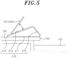
- Fig. 5 is a view showing a state in which a tablet is tilted in the portable transaction module according to the first embodiment
- Fig. 1 is a perspective view showing a state in which a portable transaction module according to a first embodiment of the present disclosure is mounted on a digital desk
- Fig. 2 is a block diagram showing a control flow of the portable transaction module according to the first embodiment
- Fig. 3 is an enlarged perspective view of the portable transaction module according to the first embodiment.
- Fig. 4 is a diagram showing
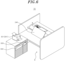
- Fig. 6 is a perspective view of a digital desk on which the portable transaction module according to the first embodiment is installed, as viewed from a teller side
- Fig. 7 is a perspective view of the digital desk shown in Fig. 6 to which a teller cash recycler (TCR) is provided, as viewed from the teller side.
- TCR teller cash recycler
- a portable transaction module 200 includes a portable board unit 210, a customer-side digital module unit 220, and a teller-side digital module unit 240.
- the portable board unit 210 may be removably placed on a customer-side desk portion 102 to be described later.
- the portable board unit 210 includes inclined surfaces which have different inclinations in a direction toward a customer and a direction toward a teller.
- the inclined surfaces of the portable board unit 210 are formed by bending or folding a plate member having a board shape.
- at least one side of the portable board unit 210 is opened without being covered by the plate member.
- the portable board unit 210 includes a bottom surface portion 211, a first inclined surface portion 212 and a second inclined surface portion 213.
- the bottom surface portion 211 of the portable board unit 210 is supported in a state of being in surface contact with a customer-side desk part 102 of a desk body 100 to be described later, so that the portable board unit 210 can be stably mounted on the customer-side desk part 102.
- the first inclined surface portion 212 extends inclined at a predetermined angle from one end of the bottom surface portion 211 to face the teller-side direction.
- the second inclined surface portion 213 extends inclined at a predetermined angle from one end of the first inclined surface portion 212 to face the customer-side direction.
- An insertion hole 214 into which a writing instrument can be inserted may be formed in the second inclined surface portion 213.
- the first inclined surface portion 212 has a first inclination angle with respect to the bottom surface portion 211 as a reference plane and the second inclined surface portion 213 has a second inclination angle with respect to the bottom surface portion 211 as the reference plane.
- the first inclination angle of the first inclined surface portion 212 is larger than the second inclination angle of the second inclined surface portion 213.
- the inclination angle of a monitor of the teller-side digital module unit 240 placed on and supported by the first inclined surface portion 212 may be greater than the inclination angle of a tablet 221 of the customer-side digital module unit 220 placed on and supported by the second inclined surface portion 213.
- the first inclined surface portion 212 may be provided with a guide rail 216 for guiding the teller digital module unit 240 in up and down directions.
- the guide rail 216 may be provided in a form of a rail that guides the teller digital module unit 240 in the up and down directions.
- the guide rail 216 guides the up-down movement of the teller digital module unit 240, so that the position of the teller digital module unit 240 can be appropriately adjusted according to a height of a stepped portion 103 of the desk body 100.
- a notification lamp 215 may be provided at an end of the second inclined surface portion 213.
- the notification lamp 215 may be lit or flashed in response to an operation signal of a personal computer (PC) 340.
- the lighting/flashing of the notification lamp 215 may be a signal notifying that a waiting customer is in a state in which consultation with a teller is possible.
- the bottom surface portion 211, the first inclined surface portion 212, and the second inclined surface portion 213 may be configured in a form of a bent plate in which the joint portions thereof are bent in a triangular shape. At least a part of the customer-side digital unit 220 may be mounted in the inner space of the bottom surface portion 211, the first inclined surface portion 212 and the second inclined surface portion 213.
- the bottom surface portion 211, the first inclined surface portion 212, and the second inclined surface portion 213 are configured in the form of the bent plate in which the joint portions thereof are bent in a triangular shape, the present disclosure is not limited to the above.
- the overall shape of the portable board unit 210 may be variously changed.
- the portable board unit 210 may be provided with the customer-side digital module unit 220 for inputting information necessary for business transactions.
- the customer-side digital module unit 220 may include at least one of a tablet 221, a sign pad 222, a pin pad 223, an identification card scanner 224, a seal scanner 225, a palm vein scanner 226, a near field communication (NFC) reader 227 and a fingerprint reader 228, which are used for information input.
- NFC near field communication
- the tablet 221 may be mounted to be tilted at a predetermined angle in the portable board unit 210.
- a conventional tilting device for tilting the tablet 221 at a predetermined angle may be applied to the portable board unit 210.
- the customer may rotate the tablet 221 about a hinge axis of the tilting device by pulling the tablet 221 by hand. Then, the rotation angle of the tablet 221 on the portable board unit 210 may be adjusted according to the viewing angle of the customer.
- the tablet 221 may be moved laterally on the second inclined surface portion 213 of the portable board unit 210. Accordingly, the customer can conveniently use the tablet 221 while placing the tablet 221 at a convenient point on the second inclined surface portion 213.
- the customer-side digital module unit 220 is configured to include at least one of the tablet 221, the sign pad 222, the pin pad 223, the identification card scanner 224, the seal scanner 225, the palm vein scanner 226, the NFC reader 227 and the fingerprint reader 228, the present disclosure is not limited thereto.
- the customer-side digital module unit 220 may further include an additional device for information input.
- the teller-side digital module unit 240 may provide a business service requested by a customer on the side of the teller-side desk portion 101.
- the teller-side digital module unit 240 may be a teller-side monitor which may be removably placed on the teller-side desk portion 101.
- a variety of information for providing a business service requested by a customer may be displayed on the teller-side monitor.
- Figs. 8 and 9 are perspective views showing states in which a portable transaction module according to a second embodiment of the present disclosure is mounted on a digital desk.
- a portable transaction module 200 includes a portable board unit 210, a customer-side digital module unit 220, a teller-side digital module unit 240, and a partition 250.
- the second embodiment has a difference from the above-described first embodiment in that it further includes the partition 250 as compared with the first embodiment. Accordingly, in describing the second embodiment of the present disclosure, there will be described mainly the difference between the second embodiment and the first embodiment, and like reference numerals are given to like components and redundant description thereof will be omitted.
- the partition 250 may be installed at a central portion on the desk body 100 to partition the desk body 100 into the teller-side desk portion 101 and the customer-side desk portion 102. In other words, the partition 250 partitions a space into a teller side space and a customer side space.
- the partition 250 may be configured as a display for outputting an image, and such a display may be a transparent display made of an entirely transparent material or an opaque display formed of at least a partly opaque material.
- the partition 250 may be provided in the form of a transparent plastic plate.
- the partition 250 may include at least one of a liquid crystal display (LCD), a light emitting diode (LED) and a head up display (HUD).
- the partition 250 may display information input by a teller through such a display.
- the partition 250 may display business transaction information required for a business transaction or a business service requested by a customer, so that the customer can grasp at a glance the information input by the teller through the partition 250.
- the partition 250 provides a customer service passage 410 of a predetermined size for a business transaction between the teller and the customer.
- the teller side space and the customer side space communicate with each other through the customer service passage 410.
- the customer service passage 410 may be a space of a predetermined size provided on one side of the partition 250.
- a transfer tray 530 for transfer of business transaction documents between the teller and the customer may be positioned in the customer service passage 410.
- the customer service passage 410 is an opening of a predetermined size formed in a lower portion of the partition 250.
- Fig. 10 is a perspective view showing a state in which a portable transaction module according to a modification of the second embodiment of the present disclosure is mounted on a digital desk.
- the partition 250 and its surrounding are sterilized through a first sterilization unit 710.
- the first sterilization unit 710 may include a sterilization lamp provided at a lower end portion of the partition 250 to sterilize the partition 250.
- the first sterilization unit 710 may be an ultraviolet (UV) sterilization lamp that irradiates UV light to the partition 250 to sterilize the partition 250.
- UV ultraviolet
- a digital desk 10 may include a desk body 100, a portable transaction module 200, a teller-side input device 310, a teller-side output device 320, and a PC 340.
- the desk body 100 may be disposed at a window in a bank where a business transaction between a teller and a customer is performed.
- the desk body 100 may include an upper plate 110 and a support 120 supporting the upper plate 110.
- the upper plate 110 may include a teller-side desk portion 101, a customer-side desk portion 102, and a stepped portion 103.
- the teller-side desk portion 101 and the customer-side desk portion 102 may be respective areas on the plate 110 which are partitioned by an imaginary border line.
- the imaginary border line may be a center line placed in the center of the upper plate 110, and the center line may extend in a left and right direction.
- the teller-side desk portion 101 and the customer-side desk portion 102 may be disposed opposite to each other with the stepped portion 103 positioned therebetween.
- the teller-side desk portion 101 may be located below the customer-side desk portion 102.
- a bank teller may be positioned on the side of the teller-side desk portion 101.
- the teller-side desk portion 101 may provide a space for a teller's work on the upper plate 110.
- a variety of office equipment and documents may be temporarily placed on the teller-side desk portion 101.
- at least one part of the teller-side digital unit 240 may be placed on the teller-side desk portion 101.
- a teller-side monitor 310 may be placed on the teller-side desk portion 101.
- the customer-side desk portion 102 may provide a space for a customer on the upper plate 110.
- the portable transaction module 200 may be removably mounted at the customer-side desk portion 102.
- the customer-side desk portion 102 may be located above the teller-side desk portion 101.
- the stepped portion 103 may be formed in the center portion of the desk body 100 so that the teller-side desk portion 101 and the customer desk portion 102 have a height difference.
- the teller-side desk portion 101 may be located below the customer-side desk portion 102 through the stepped portion 103.
- the support 120 may be provided in the form of a pair of legs supporting both side ends of the upper plate 110.
- a desk space S into which a chair for a teller can be inserted may be provided between the pair of supports 120.
- the support 120 has a structure that supports both side ends of the upper plate 110 on the side of which a teller is located, but the present disclosure is not limited thereto.
- the support 120 may have a structure that supports both side ends of the upper plate 110 on the sides of which a teller and a customer are located.
- the teller-side input device 320 may be connected to the PC 340 and the teller-side monitor 310.
- a teller may input information through the teller-side input device 320.
- the teller-side input device 320 may include a keyboard and a scanner 321 for information input.
- the teller-side output device 330 may output data for business services under the control of the PC 340.
- the teller-side output device 330 may include at least one of a paper printer 331, a passbook printer 332, a card issuing machine 333, and a teller cash recycler (TCR) 334.
- the paper printer 331, the passbook printer 332, the card issuing machine 333 and the TCR 334 may be located close to the teller-side desk portion 101 for convenience of access of the teller.
- the paper printer 331, the passbook printer 332 and the card issuing machine 333 may be located on one side of the teller-side desk portion 101
- the TCR 334 may be located on the other side of the teller-side desk portion 101.
- the PC 340 may include a PC device for controlling the teller-side monitor 310, the teller-side input device 320, and the teller-side output device 330.
- the PC 340 may be located in the desk space S located on the teller side.
- the PC 340 may be implemented by an operation device including a microprocessor, a memory and the like. The implementation method is obvious to those skilled in the art, and thus further detailed description thereof will be omitted.
- the portable transaction module 200 is configured to store data. Meanwhile, in addition to the above configurations, according to another modification of the second embodiment of the present disclosure, the portable transaction module 200
- the partition 250 provides a customer service passage 410 of a predetermined size for a business transaction between the teller and the customer.
- the customer service passage 410 is an opening of a predetermined size formed in a lower portion of the partition 250
- the portable board unit 210 is arranged to be surrounded by a lower edge of the partition 250 so that the customer service passage 410 is located on its side
- the portable board unit 210 is provided so that the partition 250 is placed at the boundary between the first inclined surface portion 212 and the second inclined surface portion 213.
- the second sterilization unit 720 is installed at a side of the portable board unit 210 in order to sterilize the customer service passage 410 which allows the teller-side desk portion 101 and the customer-side desk portion 102 to communicate.
- the second sterilization unit 720 may be a UV sterilization lamp that sterilizes the customer service passage 410.
- the second sterilization unit 720 is arranged to extend downward from the boundary between the first inclined surface portion 212 and the second inclined surface portion 213 (an upper edge of the portable board unit 210). In addition, when the side of the portable board unit 210 is open, the second sterilizing unit 720 may extend downward across the open space.
- Fig. 12 is a perspective view showing a state in which a portable transaction module according to the third embodiment of the present disclosure is mounted on a digital desk
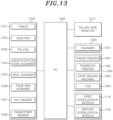
- Fig. 13 is a block diagram showing a control flow of the portable transaction module according to the third embodiment
- Fig. 14 is an enlarged perspective view of the portable transaction module according to the third embodiment
- Fig. 15 is a side view showing a digital module of the portable transaction module according to the third embodiment.
- a portable transaction module 1200 includes a portable block unit 1210, a customer-side digital module unit 1220, a portable plate unit 1230, a teller-side digital module unit 1240, and a partition 1250.
- the portable block unit 1210 may be provided in a pentahedral shape having a triangular side cross-section.
- the portable block unit 1210 may include a bottom surface portion 1211, a first inclined surface portion 1212 and a second inclined surface portion 1213.
- the bottom surface portion 1211 of the portable block unit 1210 is supported in a state of being in face-contact with the portable plate unit 1230.
- the first inclined surface portion 1212 and the second inclined surface portion 1213 may be formed to be inclined at one end and the other end of the bottom surface part 1211.
- the first inclined surface portion 1212 may extend inclined at a predetermined angle from one end of the bottom surface portion 1211 to face in a teller-side direction.
- a teller-side monitor may be provided at the first inclined surface portion 1212.
- a variety of information for providing a business service requested by a customer may be displayed on the teller-side monitor.
- the second inclined surface portion 1213 may extend inclined at a predetermined angle from one end of the first inclined surface portion 1212 to face in a customer-side direction.
- the customer-side digital module unit 1220 may be provided at the second inclined surface portion 1213. Information necessary for business transactions may be inputted through the customer-side digital module unit 1220.
- the first inclined surface portion 1212 and the second inclined surface portion 1213 may provide inclined surfaces which have different inclinations in the customer-side direction and in the teller-side direction.
- the first inclined surface portion 1212 may have a first inclination angle with respect to the bottom surface portion 1211 as a reference plane and the second inclined surface portion 1213 may have a second inclination angle with respect to the bottom surface portion 1211 as the reference plane.
- the first inclination angle of the first inclined surface portion 1212 may be smaller than the second inclination angle of the second inclined surface portion 1213.
- the inclination angle of the teller-side monitor provided at the first inclined surface portion 1212 may be smaller than the inclination angle of the customer-side digital module unit 1220 provided at the second inclined surface portion 1213. Therefore, since the screen of the teller-side monitor can be provided in a larger size than that of the screen of a customer-side monitor, the teller can effectively secure the screen view.
- a notification lamp 1215 may be provided at an upper end of the portable block unit 1210.
- the notification lamp 1215 may be lit or flashed in response to an operation signal of a personal computer (PC) 1340.
- the lighting/flashing of the notification lamp 1215 may be a signal notifying that a waiting customer is in a state in which consultation with a teller is possible.
- the portable block unit 1210 is provided in a pentahedral shape in which the joint portions of the bottom surface portion 1211, the first inclined surface portion 1212 and the second inclined surface portion 1213 are bent in a triangular shape, the present disclosure is not limited to the above.
- the overall shape of the portable block unit 1210 may be variously changed.
- the portable block unit 1210 may be provided with the customer-side digital module unit 1220 for inputting information necessary for business transactions.
- the customer-side digital module unit 1220 may include at least one of a tablet 1221, a sign pad 1222, a pin pad 1223, an identification card scanner 1224, a seal scanner 1225, a palm vein scanner 1226, a near field communication (NFC) reader 1227 and a fingerprint reader 1228, which are used for information input.
- NFC near field communication
- the customer-side digital module unit 1220 is configured to include at least one of the tablet 1221, the sign pad 1222, the pin pad 1223, the identification card scanner 1224, the seal scanner 1225, the palm vein scanner 1226, the NFC reader 1227 and the fingerprint reader 1228, the present disclosure is not limited thereto.
- the customer-side digital module unit 1220 may further include an additional device for information input.
- the portable plate unit 1230 may be provided in the form of a support plate detachably mounted on a customer desk portion 1102 of a desk body 1100 to be described later.
- the portable block unit 1210 may be placed at a central portion on an upper surface of the portable plate unit 1230.
- the partition 1250 may be installed at side portions on the upper surface of the portable plate unit 1230.
- the teller-side digital module unit 1240 may include devices for processing a business service requested by a customer.
- the teller-side digital module unit 1240 may include the teller-side monitor fixed to and supported by the portable block unit 1210.
- the partition 1250 may be installed at a central portion on the desk body 1100 to partition the desk body 1100 into the teller-side desk portion 1101 and the customer-side desk portion 1102. In other words, the partition 1250 may partition a space into a teller side space and a customer side space.
- the partition 1250 may be configured as a display for outputting an image, and such a display may be a transparent display made of an entirely transparent material or an opaque display formed of at least a partly opaque material.
- the partition 1250 may be provided in the form of a transparent plastic plate.
- the partition 1250 may include at least one of a liquid crystal display (LCD), a light emitting diode (LED) and a head up display (HUD).
- the partition 1250 may display information input by a teller through such a display.
- the partition 1250 may display business transaction information required for a business transaction or a business service requested by a customer, so that the customer can grasp at a glance the information input by the teller through the partition 1250.
- the partition 1250 may provide a customer service passage 1410 of a predetermined size for a business transaction between the teller and the customer.
- the teller side space and the customer side space may communicate with each other through the customer service passage 1410.
- the customer service passage 1410 may be provided in a form of an opening of a predetermined size in a lower portion of the partition 1250, and the portable block unit 1210 may be arranged to be surrounded by a lower edge of the partition 1250 so that the customer service passage 1410 is provided on its side.
- the customer service passage 1410 may be provided in a form of a space of a predetermined size provided at one side of the partition 1250.
- the first sterilization unit 1710 may include a sterilization lamp provided at a lower end portion of the partition 1250 to sterilize the partition 1250.
- the first sterilization unit 1710 may be an ultraviolet (UV) sterilization lamp that irradiates UV light to the partition 1250 and its surroundings to sterilize the partition 1250 and its surroundings.
- UV ultraviolet
- the second sterilization unit 1720 may include a sterilization lamp provided at a side portion of the portable block unit in order to sterilize the customer service passage 1410 which allows the teller-side desk portion 1101 and the customer-side desk portion 1102 to communicate.
- the second sterilization unit 1720 may be a UV sterilization lamp that sterilizes the customer service passage 1410.
- the second sterilization unit 1720 may be arranged to extend downward from the boundary between the first inclined surface portion 1212 and the second inclined surface portion 1213 (an upper edge of the portable block unit 1210).
- Fig. 16 is a perspective view of a digital desk on which the portable transaction module according to the third embodiment is installed, as viewed from a teller side
- Fig. 17 is a perspective view of the digital desk shown in Fig. 16 to which teller cash recycler (TCR) is provided, as viewed from the teller side.
- TCR teller cash recycler
- a digital desk 20 may include a desk body 1100, a portable transaction module 1200, a teller-side input device 1320, a teller-side output device 1330, and a PC 1340.
- the desk body 1100 may be disposed at a window in a bank where a business transaction between a teller and a customer is performed.
- the desk body 1100 may include an upper plate 1110 and a support 1120 supporting the upper plate 1110.
- the upper plate 1110 may include a teller-side desk portion 1101, a customer-side desk portion 1102, and a stepped portion 1103.
- the teller-side desk portion 1101 and the customer-side desk portion 1102 may be respective areas on the plate 1110 which are partitioned by an imaginary border line.
- the imaginary border line may be a center line placed in the center of the upper plate 1110, and the center line may extend in a left and right direction.
- the teller-side desk portion 1101 and the customer-side desk portion 1102 may be disposed opposite to each other.
- a bank teller may be positioned on the side of the teller-side desk portion 1101.
- the teller-side desk portion 1101 may provide a space for a teller's work on the upper plate 1110.
- a variety of office equipment and documents may be temporarily placed on the teller-side desk portion 1101.
- at least one part of the customer-side digital module unit 1220 may be placed on the teller-side desk portion 1101.
- the customer-side desk portion 1102 may provide a space for a customer on the upper plate 1110.
- the customer-side desk portion 1102 may be distinguished from the teller-side desk portion 1101 by the partition 1250 interposed therebetween.
- At least one part of the customer-side digital module unit 1220 may be placed on the customer-side desk portion 1102.
- the support 1120 may be provided in the form of a pair of legs supporting both side ends of the upper plate 1110.
- a desk space S into which a chair for a customer or a chair for a teller can be inserted may be provided between the pair of supports 1120.
- the support 1120 has a structure that supports both side ends of the upper plate 1110 on the sides of which a teller and a customer are located, but the present disclosure is not limited thereto.
- the support 1120 may have a structure that supports both side ends of the upper plate 1110 on the side of which a teller is located.
- the teller-side input device 1320 may be connected to the PC 1340 and the teller-side monitor 1310. A teller may input information through the teller-side input device 1320.
- the teller-side input device 1320 may include a keyboard and a scanner 1321 for information input.
- the teller-side output device 1330 may output data for business services under the control of the PC 1340.
- the teller-side output device 1330 may include at least one of a paper printer 1331, a passbook printer 1332, a card issuing machine 1333, and a teller cash recycler (TCR) 1334.
- the paper printer 1331, the passbook printer 1332, the card issuing machine 1333 and the TCR 1334 may be located close to the teller-side desk portion 1101 for convenience of access of the teller.
- the paper printer 1331, the passbook printer 332 and the card issuing machine 1333 may be located on one side of the teller-side desk portion 1101, and the TCR 1334 may be located on the other side of the teller-side desk portion 1101.
- the PC 1340 may include a PC device for controlling the teller-side monitor 1310, the teller-side input device 1320, and the teller-side output device 1330.
- the PC 1340 may be located in the desk space S located on the teller side.
- the PC 1340 may be implemented by an operation device including a microprocessor, a memory and the like. The implementation method is obvious to those skilled in the art, and thus further detailed description thereof will be omitted.
- Fig. 18 is a front view showing a digital desk according one embodiment of the present disclosure to which an advertisement module is additionally installed.
- an advertisement module 1600 may be additionally installed to the desk body 1100.
- the advertisement module 1600 may be provided at one side of the desk body 1100, and may be arranged to be perpendicular to the upper plate 1110.
- the advertisement module 1600 may include a display which is capable of displaying specific information, photographs, graphs and the like, and such a display may be at least one of an LCD, an LED and a HUD.
- the advertisement module 1600 may provide an advertisement board function for advertising a product of a bank, for example. Accordingly, a customer may receive information on various types of bank products through the advertisement module 1600.As described above, in accordance with the embodiments of the present disclosure, it is possible to accurately distinguish between a device for the customer and a device for the teller at a bank window, and the customer can use the device for the customer. In addition, it is possible to implement a self-banking service with face-to-face assist, thereby minimizing business services requested by customers and enhancing work efficiency. Further, it is possible to minimize materials put on the desk through the digitalized work environment. Moreover, even in the epidemic of an infectious disease, smooth consultation can be performed between the teller and the customer since the possibility of infection is reduced.
Landscapes
- Engineering & Computer Science (AREA)
- Business, Economics & Management (AREA)
- Physics & Mathematics (AREA)
- General Physics & Mathematics (AREA)
- Accounting & Taxation (AREA)
- Theoretical Computer Science (AREA)
- Strategic Management (AREA)
- General Business, Economics & Management (AREA)
- Finance (AREA)
- Computer Networks & Wireless Communication (AREA)
- Economics (AREA)
- Marketing (AREA)
- Health & Medical Sciences (AREA)
- Toxicology (AREA)
- Technology Law (AREA)
- Entrepreneurship & Innovation (AREA)
- Human Resources & Organizations (AREA)
- Development Economics (AREA)
- Artificial Intelligence (AREA)
- Electromagnetism (AREA)
- Computer Vision & Pattern Recognition (AREA)
- General Health & Medical Sciences (AREA)
- Quality & Reliability (AREA)
- General Engineering & Computer Science (AREA)
- Data Mining & Analysis (AREA)
- Operations Research (AREA)
- Human Computer Interaction (AREA)
- Computer Hardware Design (AREA)
- Tourism & Hospitality (AREA)
- Mathematical Physics (AREA)
- Financial Or Insurance-Related Operations Such As Payment And Settlement (AREA)
- Cash Registers Or Receiving Machines (AREA)
- Casings For Electric Apparatus (AREA)
Description
- The present disclosure relates to a portable transaction module.
- In general, a teller in a bank prepares various office equipment and documents in order to consult with a customer and provide necessary information to the customer. By using the office equipment and the documents placed on a digital desk or in a drawer, the teller can provide necessary information to the customer while doing his/her work.
- However, putting the office equipment and the documents on the digital desk, the top of the desk can be messy and the space on the desk may be insufficient to provide materials to a customer when consulting with the customer. Meanwhile, when the office equipment, the documents and the like are put in the drawer, it may be inconvenient to use the office equipment and the documents and the like as the teller needs to take out the office equipment and the documents and the like from the drawer. In particular, in an epidemic of an infectious disease, when a teller and a customer make face-to-face consultation with a digital desk between them, proper consultation between the teller and the customer may be difficult due to the fear of infection.
-
US 2006/289629 A1 discloses a financial transactions processing system including a teller display screen and a customer display screen, both of which can be coupled to a teller computer. The teller computer can be operably connected to a bank computer. The teller computer provides the teller display screen with a first set of information to be displayed on the teller display screen, and supplies the customer display screen with a second set of information to be displayed on the customer display screen, such that the customer display screen and the teller display screen display different sets of information. -
US 2013/279106 A1 discloses support systems and related methods for supporting tablets and monitors, e.g. a stand that includes a monitor support portion configured to support a monitor and a tablet support portion configured to support a tablet. -
EP 3 451 304 A1 discloses a point of sale terminal. The point of sale terminal may include a housing, a customer display, and a payment device. The housing may define a customer display opening and a tablet opening. The customer display may be located within the housing and arranged to be visible through the customer display opening. The payment device may be located within the housing proximate customer display opening. - In view of the above, the present disclosure provides a portable transaction module which allows a teller and a customer to efficiently perform business transactions therebetween.The present invention is as defined by the appended claims.
-
-
Fig. 1 is a perspective view showing a state in which a portable transaction module according to a first embodiment of the present disclosure is mounted on a digital desk, the first embodiment of the portable transaction module not falling within the scope of the present invention as claimed. -
Fig. 2 is a block diagram showing a control flow of the portable transaction module according to the first embodiment. -
Fig. 3 is an enlarged perspective view of the portable transaction module according to the first embodiment. -
Fig. 4 is a diagram showing a state in which a monitor for a teller is mounted in the portable transaction module according to the first embodiment. -
Fig. 5 is a view showing a state in which a tablet is tilted in the portable transaction module according to the first embodiment. -
Fig. 6 is a perspective view of a digital desk on which the portable transaction module according to the first embodiment is installed, as viewed from a teller side. -
Fig. 7 is a perspective view of the digital desk shown inFig. 6 to which a teller cash recycler (TCR) is provided, as viewed from the teller side. -
Figs. 8 and9 are perspective views showing states in which a portable transaction module according to a second embodiment of the present disclosure is mounted on a digital desk, the second embodiment of the portable transaction module not falling within the scope of the present invention as claimed. -
Fig. 10 is a perspective view showing a state in which a portable transaction module according to a modification of the second embodiment of the present disclosure is mounted in a customer service passage, the modification of the second embodiment of the present disclosure according toFig. 10 not falling within the scope of the present invention as claimed. -
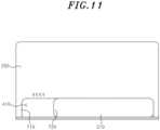
Fig. 11 is a front view showing a portable transaction module according to another modification of the second embodiment of the present disclosure, the modification of the second embodiment of the present invention according toFig. 11 falling within the scope of the present invention as claimed. -
Fig. 12 is a perspective view showing a state in which a portable transaction module according to a third embodiment of the present disclosure is mounted on a digital desk, the third embodiment of the portable transaction module not falling within the scope of the present invention as claimed. -
Fig. 13 is a block diagram showing a control flow of the portable transaction module according to the third embodiment. -
Fig. 14 is an enlarged perspective view of the portable transaction module according to the third embodiment. -
Fig. 15 is a side view showing a digital module of the portable transaction module according to the third embodiment. -
Fig. 16 is a perspective view of a digital desk on which the portable transaction module according to the third embodiment is installed, as viewed from a teller side. -
Fig. 17 is a perspective view of the digital desk shown inFig. 16 to which teller cash recycler (TCR) is provided, as viewed from the teller side. -
Fig. 18 is a front view showing a digital desk according one embodiment of the present disclosure to which an advertisement module is additionally , the one embodiment of the present disclosure with the added advertisement module not falling within the scope of the present invention as claimed. - Hereinafter, configurations and operations of embodiments will be described in detail with reference to the accompanying drawings.
- In describing the embodiments of the present disclosure, the detailed descriptions of well-known functions or configurations will be omitted if it is determined that the detailed descriptions of well-known functions or configurations may unnecessarily make obscure the present disclosure.
- The terms used herein, including ordinal numbers such as "first" and "second" may be used to describe, and not to limit, various components. The terms simply distinguish the components from one another.
- When it is said that a component is "connected" or "linked" to another component, it should be understood that the former component may be directly connected or linked to the latter component or a third component may be interposed between the two components.
- Specific terms in the present disclosure are used simply to describe specific embodiments without limiting the present disclosure.
- Hereinafter, an embodiment of the present disclosure will be described in detail with reference to the accompanying drawings.
- A portable transaction module according to embodiments of the present disclosure includes a portable unit. Further, the portable unit includes a portable board unit and a portable block unit which are described later.
-
Fig. 1 is a perspective view showing a state in which a portable transaction module according to a first embodiment of the present disclosure is mounted on a digital desk,Fig. 2 is a block diagram showing a control flow of the portable transaction module according to the first embodiment, andFig. 3 is an enlarged perspective view of the portable transaction module according to the first embodiment.Fig. 4 is a diagram showing a state in which a monitor for a teller is mounted in the portable transaction module according to the first embodiment,Fig. 5 is a view showing a state in which a tablet is tilted in the portable transaction module according to the first embodiment,Fig. 6 is a perspective view of a digital desk on which the portable transaction module according to the first embodiment is installed, as viewed from a teller side, andFig. 7 is a perspective view of the digital desk shown inFig. 6 to which a teller cash recycler (TCR) is provided, as viewed from the teller side. - Referring
Figs. 1 to 7 , aportable transaction module 200 according to the first embodiment of the present disclosure includes aportable board unit 210, a customer-sidedigital module unit 220, and a teller-sidedigital module unit 240. - The
portable board unit 210 may be removably placed on a customer-side desk portion 102 to be described later. Theportable board unit 210 includes inclined surfaces which have different inclinations in a direction toward a customer and a direction toward a teller. The inclined surfaces of theportable board unit 210 are formed by bending or folding a plate member having a board shape. In addition, at least one side of theportable board unit 210 is opened without being covered by the plate member. - To that end, the
portable board unit 210 includes abottom surface portion 211, a firstinclined surface portion 212 and a secondinclined surface portion 213. For example, thebottom surface portion 211 of theportable board unit 210 is supported in a state of being in surface contact with a customer-side desk part 102 of adesk body 100 to be described later, so that theportable board unit 210 can be stably mounted on the customer-side desk part 102. - The first
inclined surface portion 212 extends inclined at a predetermined angle from one end of thebottom surface portion 211 to face the teller-side direction. The secondinclined surface portion 213 extends inclined at a predetermined angle from one end of the firstinclined surface portion 212 to face the customer-side direction. Aninsertion hole 214 into which a writing instrument can be inserted may be formed in the secondinclined surface portion 213. In addition, the firstinclined surface portion 212 has a first inclination angle with respect to thebottom surface portion 211 as a reference plane and the secondinclined surface portion 213 has a second inclination angle with respect to thebottom surface portion 211 as the reference plane. The first inclination angle of the firstinclined surface portion 212 is larger than the second inclination angle of the secondinclined surface portion 213. Accordingly, the inclination angle of a monitor of the teller-sidedigital module unit 240 placed on and supported by the firstinclined surface portion 212 may be greater than the inclination angle of atablet 221 of the customer-sidedigital module unit 220 placed on and supported by the secondinclined surface portion 213. - The first
inclined surface portion 212 may be provided with aguide rail 216 for guiding the tellerdigital module unit 240 in up and down directions. Theguide rail 216 may be provided in a form of a rail that guides the tellerdigital module unit 240 in the up and down directions. Theguide rail 216 guides the up-down movement of the tellerdigital module unit 240, so that the position of the tellerdigital module unit 240 can be appropriately adjusted according to a height of astepped portion 103 of thedesk body 100. - In addition, a
notification lamp 215 may be provided at an end of the secondinclined surface portion 213. Thenotification lamp 215 may be lit or flashed in response to an operation signal of a personal computer (PC) 340. As an example, the lighting/flashing of thenotification lamp 215 may be a signal notifying that a waiting customer is in a state in which consultation with a teller is possible. - The
bottom surface portion 211, the firstinclined surface portion 212, and the secondinclined surface portion 213 may be configured in a form of a bent plate in which the joint portions thereof are bent in a triangular shape. At least a part of the customer-sidedigital unit 220 may be mounted in the inner space of thebottom surface portion 211, the firstinclined surface portion 212 and the secondinclined surface portion 213. - In the present embodiment, although the
bottom surface portion 211, the firstinclined surface portion 212, and the secondinclined surface portion 213 are configured in the form of the bent plate in which the joint portions thereof are bent in a triangular shape, the present disclosure is not limited to the above. The overall shape of theportable board unit 210 may be variously changed. - The
portable board unit 210 may be provided with the customer-sidedigital module unit 220 for inputting information necessary for business transactions. The customer-sidedigital module unit 220 may include at least one of atablet 221, asign pad 222, apin pad 223, anidentification card scanner 224, aseal scanner 225, apalm vein scanner 226, a near field communication (NFC)reader 227 and afingerprint reader 228, which are used for information input. - In particular, the
tablet 221 may be mounted to be tilted at a predetermined angle in theportable board unit 210. To that end, a conventional tilting device for tilting thetablet 221 at a predetermined angle may be applied to theportable board unit 210. As an example, the customer may rotate thetablet 221 about a hinge axis of the tilting device by pulling thetablet 221 by hand. Then, the rotation angle of thetablet 221 on theportable board unit 210 may be adjusted according to the viewing angle of the customer. - Further, the
tablet 221 may be moved laterally on the secondinclined surface portion 213 of theportable board unit 210. Accordingly, the customer can conveniently use thetablet 221 while placing thetablet 221 at a convenient point on the secondinclined surface portion 213. - In the present embodiment, although the customer-side
digital module unit 220 is configured to include at least one of thetablet 221, thesign pad 222, thepin pad 223, theidentification card scanner 224, theseal scanner 225, thepalm vein scanner 226, theNFC reader 227 and thefingerprint reader 228, the present disclosure is not limited thereto. The customer-sidedigital module unit 220 may further include an additional device for information input. - The teller-side
digital module unit 240 may provide a business service requested by a customer on the side of the teller-side desk portion 101. The teller-sidedigital module unit 240 may be a teller-side monitor which may be removably placed on the teller-side desk portion 101. A variety of information for providing a business service requested by a customer may be displayed on the teller-side monitor. -
Figs. 8 and9 are perspective views showing states in which a portable transaction module according to a second embodiment of the present disclosure is mounted on a digital desk. - As shown in
Figs. 8 and9 , aportable transaction module 200 according to the second embodiment of the present disclosure includes aportable board unit 210, a customer-sidedigital module unit 220, a teller-sidedigital module unit 240, and apartition 250. - The second embodiment has a difference from the above-described first embodiment in that it further includes the
partition 250 as compared with the first embodiment. Accordingly, in describing the second embodiment of the present disclosure, there will be described mainly the difference between the second embodiment and the first embodiment, and like reference numerals are given to like components and redundant description thereof will be omitted. - The
partition 250 may be installed at a central portion on thedesk body 100 to partition thedesk body 100 into the teller-side desk portion 101 and the customer-side desk portion 102. In other words, thepartition 250 partitions a space into a teller side space and a customer side space. Thepartition 250 may be configured as a display for outputting an image, and such a display may be a transparent display made of an entirely transparent material or an opaque display formed of at least a partly opaque material. As another example, thepartition 250 may be provided in the form of a transparent plastic plate. - In case the
partition 250 is configured as a display, thepartition 250 may include at least one of a liquid crystal display (LCD), a light emitting diode (LED) and a head up display (HUD). Thepartition 250 may display information input by a teller through such a display. For example, thepartition 250 may display business transaction information required for a business transaction or a business service requested by a customer, so that the customer can grasp at a glance the information input by the teller through thepartition 250. - The
partition 250 provides acustomer service passage 410 of a predetermined size for a business transaction between the teller and the customer. The teller side space and the customer side space communicate with each other through thecustomer service passage 410. As an example not covered by the appended claims, as shown inFig. 8 , thecustomer service passage 410 may be a space of a predetermined size provided on one side of thepartition 250. Atransfer tray 530 for transfer of business transaction documents between the teller and the customer may be positioned in thecustomer service passage 410. In accordance with the invention as claimed, as shown inFig. 9 , thecustomer service passage 410 is an opening of a predetermined size formed in a lower portion of thepartition 250. -
Fig. 10 is a perspective view showing a state in which a portable transaction module according to a modification of the second embodiment of the present disclosure is mounted on a digital desk. - As shown in
Fig. 10 , in theportable transaction module 200 according to the modification of the second embodiment, thepartition 250 and its surrounding are sterilized through afirst sterilization unit 710. - The
first sterilization unit 710 may include a sterilization lamp provided at a lower end portion of thepartition 250 to sterilize thepartition 250. For example, thefirst sterilization unit 710 may be an ultraviolet (UV) sterilization lamp that irradiates UV light to thepartition 250 to sterilize thepartition 250. - Meanwhile, a
digital desk 10 according to one embodiment of the present disclosure may include adesk body 100, aportable transaction module 200, a teller-side input device 310, a teller-side output device 320, and aPC 340. - Specifically, the
desk body 100 may be disposed at a window in a bank where a business transaction between a teller and a customer is performed. Thedesk body 100 may include anupper plate 110 and asupport 120 supporting theupper plate 110. - The
upper plate 110 may include a teller-side desk portion 101, a customer-side desk portion 102, and a steppedportion 103. The teller-side desk portion 101 and the customer-side desk portion 102 may be respective areas on theplate 110 which are partitioned by an imaginary border line. The imaginary border line may be a center line placed in the center of theupper plate 110, and the center line may extend in a left and right direction. - The teller-
side desk portion 101 and the customer-side desk portion 102 may be disposed opposite to each other with the steppedportion 103 positioned therebetween. In this case, the teller-side desk portion 101 may be located below the customer-side desk portion 102. A bank teller may be positioned on the side of the teller-side desk portion 101. The teller-side desk portion 101 may provide a space for a teller's work on theupper plate 110. - A variety of office equipment and documents may be temporarily placed on the teller-
side desk portion 101. In addition, at least one part of the teller-sidedigital unit 240 may be placed on the teller-side desk portion 101. For example, a teller-side monitor 310 may be placed on the teller-side desk portion 101. - Further, the customer-
side desk portion 102 may provide a space for a customer on theupper plate 110. Theportable transaction module 200 may be removably mounted at the customer-side desk portion 102. The customer-side desk portion 102 may be located above the teller-side desk portion 101. - In addition, the stepped
portion 103 may be formed in the center portion of thedesk body 100 so that the teller-side desk portion 101 and thecustomer desk portion 102 have a height difference. In this case, the teller-side desk portion 101 may be located below the customer-side desk portion 102 through the steppedportion 103. - The
support 120 may be provided in the form of a pair of legs supporting both side ends of theupper plate 110. A desk space S into which a chair for a teller can be inserted may be provided between the pair ofsupports 120. - In the present embodiment, the
support 120 has a structure that supports both side ends of theupper plate 110 on the side of which a teller is located, but the present disclosure is not limited thereto. Thesupport 120 may have a structure that supports both side ends of theupper plate 110 on the sides of which a teller and a customer are located. - The teller-
side input device 320 may be connected to thePC 340 and the teller-side monitor 310. A teller may input information through the teller-side input device 320. The teller-side input device 320 may include a keyboard and ascanner 321 for information input. - The teller-
side output device 330 may output data for business services under the control of thePC 340. The teller-side output device 330 may include at least one of apaper printer 331, apassbook printer 332, acard issuing machine 333, and a teller cash recycler (TCR) 334. - The
paper printer 331, thepassbook printer 332, thecard issuing machine 333 and theTCR 334 may be located close to the teller-side desk portion 101 for convenience of access of the teller. For example, thepaper printer 331, thepassbook printer 332 and thecard issuing machine 333 may be located on one side of the teller-side desk portion 101, and theTCR 334 may be located on the other side of the teller-side desk portion 101. - The
PC 340 may include a PC device for controlling the teller-side monitor 310, the teller-side input device 320, and the teller-side output device 330. ThePC 340 may be located in the desk space S located on the teller side. ThePC 340 may be implemented by an operation device including a microprocessor, a memory and the like. The implementation method is obvious to those skilled in the art, and thus further detailed description thereof will be omitted. - Meanwhile, in addition to the above configurations, according to another modification of the second embodiment of the present disclosure, the
portable transaction module 200 - further includes a
second sterilization unit 720. ReferringFig. 11 , thepartition 250 provides acustomer service passage 410 of a predetermined size for a business transaction between the teller and the customer. Thecustomer service passage 410 is an opening of a predetermined size formed in a lower portion of thepartition 250, theportable board unit 210 is arranged to be surrounded by a lower edge of thepartition 250 so that thecustomer service passage 410 is located on its side, theportable board unit 210 is provided so that thepartition 250 is placed at the boundary between the firstinclined surface portion 212 and the secondinclined surface portion 213. - The
second sterilization unit 720 is installed at a side of theportable board unit 210 in order to sterilize thecustomer service passage 410 which allows the teller-side desk portion 101 and the customer-side desk portion 102 to communicate. Thesecond sterilization unit 720 may be a UV sterilization lamp that sterilizes thecustomer service passage 410. Thesecond sterilization unit 720 is arranged to extend downward from the boundary between the firstinclined surface portion 212 and the second inclined surface portion 213 (an upper edge of the portable board unit 210). In addition, when the side of theportable board unit 210 is open, thesecond sterilizing unit 720 may extend downward across the open space. - Hereinafter, a third embodiment of the present disclosure will be described in detail with reference to
Figs. 12 to 18 . -
Fig. 12 is a perspective view showing a state in which a portable transaction module according to the third embodiment of the present disclosure is mounted on a digital desk,Fig. 13 is a block diagram showing a control flow of the portable transaction module according to the third embodiment,Fig. 14 is an enlarged perspective view of the portable transaction module according to the third embodiment, andFig. 15 is a side view showing a digital module of the portable transaction module according to the third embodiment. - Referring
Figs. 12 to 15 , aportable transaction module 1200 according to the third embodiment of the present disclosure includes aportable block unit 1210, a customer-sidedigital module unit 1220, aportable plate unit 1230, a teller-sidedigital module unit 1240, and apartition 1250. - Specifically, the
portable block unit 1210 may be provided in a pentahedral shape having a triangular side cross-section. Theportable block unit 1210 may include abottom surface portion 1211, a firstinclined surface portion 1212 and a secondinclined surface portion 1213. For example, thebottom surface portion 1211 of theportable block unit 1210 is supported in a state of being in face-contact with theportable plate unit 1230. The firstinclined surface portion 1212 and the secondinclined surface portion 1213 may be formed to be inclined at one end and the other end of thebottom surface part 1211. - The first
inclined surface portion 1212 may extend inclined at a predetermined angle from one end of thebottom surface portion 1211 to face in a teller-side direction. A teller-side monitor may be provided at the firstinclined surface portion 1212. A variety of information for providing a business service requested by a customer may be displayed on the teller-side monitor. - The second
inclined surface portion 1213 may extend inclined at a predetermined angle from one end of the firstinclined surface portion 1212 to face in a customer-side direction. The customer-sidedigital module unit 1220 may be provided at the secondinclined surface portion 1213. Information necessary for business transactions may be inputted through the customer-sidedigital module unit 1220. - The first
inclined surface portion 1212 and the secondinclined surface portion 1213 may provide inclined surfaces which have different inclinations in the customer-side direction and in the teller-side direction. - The first
inclined surface portion 1212 may have a first inclination angle with respect to thebottom surface portion 1211 as a reference plane and the secondinclined surface portion 1213 may have a second inclination angle with respect to thebottom surface portion 1211 as the reference plane. In this case, the first inclination angle of the firstinclined surface portion 1212 may be smaller than the second inclination angle of the secondinclined surface portion 1213. Accordingly, the inclination angle of the teller-side monitor provided at the firstinclined surface portion 1212 may be smaller than the inclination angle of the customer-sidedigital module unit 1220 provided at the secondinclined surface portion 1213. Therefore, since the screen of the teller-side monitor can be provided in a larger size than that of the screen of a customer-side monitor, the teller can effectively secure the screen view. - A
notification lamp 1215 may be provided at an upper end of theportable block unit 1210. Thenotification lamp 1215 may be lit or flashed in response to an operation signal of a personal computer (PC) 1340. As an example, the lighting/flashing of thenotification lamp 1215 may be a signal notifying that a waiting customer is in a state in which consultation with a teller is possible. - In the present embodiment, although the
portable block unit 1210 is provided in a pentahedral shape in which the joint portions of thebottom surface portion 1211, the firstinclined surface portion 1212 and the secondinclined surface portion 1213 are bent in a triangular shape, the present disclosure is not limited to the above. The overall shape of theportable block unit 1210 may be variously changed. - The
portable block unit 1210 may be provided with the customer-sidedigital module unit 1220 for inputting information necessary for business transactions. For example, the customer-sidedigital module unit 1220 may include at least one of atablet 1221, asign pad 1222, apin pad 1223, anidentification card scanner 1224, aseal scanner 1225, apalm vein scanner 1226, a near field communication (NFC)reader 1227 and afingerprint reader 1228, which are used for information input. - In the present embodiment, although the customer-side
digital module unit 1220 is configured to include at least one of thetablet 1221, thesign pad 1222, thepin pad 1223, theidentification card scanner 1224, theseal scanner 1225, thepalm vein scanner 1226, theNFC reader 1227 and thefingerprint reader 1228, the present disclosure is not limited thereto. The customer-sidedigital module unit 1220 may further include an additional device for information input. - The
portable plate unit 1230 may be provided in the form of a support plate detachably mounted on acustomer desk portion 1102 of adesk body 1100 to be described later. Theportable block unit 1210 may be placed at a central portion on an upper surface of theportable plate unit 1230. In addition, thepartition 1250 may be installed at side portions on the upper surface of theportable plate unit 1230. - The teller-side
digital module unit 1240 may include devices for processing a business service requested by a customer. For example, the teller-sidedigital module unit 1240 may include the teller-side monitor fixed to and supported by theportable block unit 1210. - The
partition 1250 may be installed at a central portion on thedesk body 1100 to partition thedesk body 1100 into the teller-side desk portion 1101 and the customer-side desk portion 1102. In other words, thepartition 1250 may partition a space into a teller side space and a customer side space. Thepartition 1250 may be configured as a display for outputting an image, and such a display may be a transparent display made of an entirely transparent material or an opaque display formed of at least a partly opaque material. As another example, thepartition 1250 may be provided in the form of a transparent plastic plate. - In case the
partition 1250 is configured as a display, thepartition 1250 may include at least one of a liquid crystal display (LCD), a light emitting diode (LED) and a head up display (HUD). Thepartition 1250 may display information input by a teller through such a display. For example, thepartition 1250 may display business transaction information required for a business transaction or a business service requested by a customer, so that the customer can grasp at a glance the information input by the teller through thepartition 1250. - The
partition 1250 may provide acustomer service passage 1410 of a predetermined size for a business transaction between the teller and the customer. The teller side space and the customer side space may communicate with each other through thecustomer service passage 1410. As an example, thecustomer service passage 1410 may be provided in a form of an opening of a predetermined size in a lower portion of thepartition 1250, and theportable block unit 1210 may be arranged to be surrounded by a lower edge of thepartition 1250 so that thecustomer service passage 1410 is provided on its side. Alternatively, thecustomer service passage 1410 may be provided in a form of a space of a predetermined size provided at one side of thepartition 1250. - The
first sterilization unit 1710 may include a sterilization lamp provided at a lower end portion of thepartition 1250 to sterilize thepartition 1250. For example, thefirst sterilization unit 1710 may be an ultraviolet (UV) sterilization lamp that irradiates UV light to thepartition 1250 and its surroundings to sterilize thepartition 1250 and its surroundings. - The
second sterilization unit 1720 may include a sterilization lamp provided at a side portion of the portable block unit in order to sterilize thecustomer service passage 1410 which allows the teller-side desk portion 1101 and the customer-side desk portion 1102 to communicate. For example, thesecond sterilization unit 1720 may be a UV sterilization lamp that sterilizes thecustomer service passage 1410. Thesecond sterilization unit 1720 may be arranged to extend downward from the boundary between the firstinclined surface portion 1212 and the second inclined surface portion 1213 (an upper edge of the portable block unit 1210). -
Fig. 16 is a perspective view of a digital desk on which the portable transaction module according to the third embodiment is installed, as viewed from a teller side, andFig. 17 is a perspective view of the digital desk shown inFig. 16 to which teller cash recycler (TCR) is provided, as viewed from the teller side. - Further, as shown in
Figs. 16 and17 , a digital desk 20 according to one embodiment of the present disclosure may include adesk body 1100, aportable transaction module 1200, a teller-side input device 1320, a teller-side output device 1330, and aPC 1340. - Specifically, the
desk body 1100 may be disposed at a window in a bank where a business transaction between a teller and a customer is performed. Thedesk body 1100 may include anupper plate 1110 and asupport 1120 supporting theupper plate 1110. - The
upper plate 1110 may include a teller-side desk portion 1101, a customer-side desk portion 1102, and a stepped portion 1103. The teller-side desk portion 1101 and the customer-side desk portion 1102 may be respective areas on theplate 1110 which are partitioned by an imaginary border line. The imaginary border line may be a center line placed in the center of theupper plate 1110, and the center line may extend in a left and right direction. - The teller-
side desk portion 1101 and the customer-side desk portion 1102 may be disposed opposite to each other. A bank teller may be positioned on the side of the teller-side desk portion 1101. The teller-side desk portion 1101 may provide a space for a teller's work on theupper plate 1110. A variety of office equipment and documents may be temporarily placed on the teller-side desk portion 1101. In addition, at least one part of the customer-sidedigital module unit 1220 may be placed on the teller-side desk portion 1101. - Further, the customer-
side desk portion 1102 may provide a space for a customer on theupper plate 1110. The customer-side desk portion 1102 may be distinguished from the teller-side desk portion 1101 by thepartition 1250 interposed therebetween. At least one part of the customer-sidedigital module unit 1220 may be placed on the customer-side desk portion 1102. - The
support 1120 may be provided in the form of a pair of legs supporting both side ends of theupper plate 1110. A desk space S into which a chair for a customer or a chair for a teller can be inserted may be provided between the pair ofsupports 1120. In the present embodiment, thesupport 1120 has a structure that supports both side ends of theupper plate 1110 on the sides of which a teller and a customer are located, but the present disclosure is not limited thereto. Thesupport 1120 may have a structure that supports both side ends of theupper plate 1110 on the side of which a teller is located. - The teller-
side input device 1320 may be connected to thePC 1340 and the teller-side monitor 1310. A teller may input information through the teller-side input device 1320. The teller-side input device 1320 may include a keyboard and ascanner 1321 for information input. - The teller-
side output device 1330 may output data for business services under the control of thePC 1340. The teller-side output device 1330 may include at least one of apaper printer 1331, apassbook printer 1332, acard issuing machine 1333, and a teller cash recycler (TCR) 1334. - The
paper printer 1331, thepassbook printer 1332, thecard issuing machine 1333 and theTCR 1334 may be located close to the teller-side desk portion 1101 for convenience of access of the teller. For example, thepaper printer 1331, thepassbook printer 332 and thecard issuing machine 1333 may be located on one side of the teller-side desk portion 1101, and theTCR 1334 may be located on the other side of the teller-side desk portion 1101. - The
PC 1340 may include a PC device for controlling the teller-side monitor 1310, the teller-side input device 1320, and the teller-side output device 1330. ThePC 1340 may be located in the desk space S located on the teller side. ThePC 1340 may be implemented by an operation device including a microprocessor, a memory and the like. The implementation method is obvious to those skilled in the art, and thus further detailed description thereof will be omitted. -
Fig. 18 is a front view showing a digital desk according one embodiment of the present disclosure to which an advertisement module is additionally installed. - As shown in
Fig. 18 , anadvertisement module 1600 may be additionally installed to thedesk body 1100. Theadvertisement module 1600 may be provided at one side of thedesk body 1100, and may be arranged to be perpendicular to theupper plate 1110. - The
advertisement module 1600 may include a display which is capable of displaying specific information, photographs, graphs and the like, and such a display may be at least one of an LCD, an LED and a HUD. - The
advertisement module 1600 may provide an advertisement board function for advertising a product of a bank, for example. Accordingly, a customer may receive information on various types of bank products through the advertisement module 1600.As described above, in accordance with the embodiments of the present disclosure, it is possible to accurately distinguish between a device for the customer and a device for the teller at a bank window, and the customer can use the device for the customer. In addition, it is possible to implement a self-banking service with face-to-face assist, thereby minimizing business services requested by customers and enhancing work efficiency. Further, it is possible to minimize materials put on the desk through the digitalized work environment. Moreover, even in the epidemic of an infectious disease, smooth consultation can be performed between the teller and the customer since the possibility of infection is reduced.
Claims (5)
- A portable transaction module to be placed at a space where business transactions between a teller and a customer are performed, the portable transaction module comprising:a portable unit;a customer-side digital module unit (220), for inputting information necessary for the business transactions, mounted at one side of the portable unit; a partition (250) for partitioning the space into a teller side space and a customer side space;a customer service passage (410) through which the teller side space and the customer side space communicate with each other, wherein the customer service passage (410) is an opening of a predetermined size formed in a lower portion of the partition (250);wherein the portable unit includes a portable board unit (210), wherein the portable board unit (1210) is formed by bending a plate member having a board shape,at least one side of the portable board unit (1210) is opened,the portable board unit (1210) includes:a bottom surface portion (1211) having a reference plane;a first inclined surface portion (1212) inclined at a first inclination angle with respect to the reference plane to face the teller; anda second inclined surface portion (1213) inclined at a second inclination angle with respect to the reference plane to face the customer, wherein the first inclination angle is larger than the second inclination angle, characterized in that:the portable board unit (210) is arranged to be surrounded by a lower edge of the partition (250) so that the customer service passage (410) is located on its side;the portable board unit (210) is provided so that the partition (250) is placed at the boundary between the first inclined surface portion (212) and the second inclined surface portion (213);the portable board unit (210) further includes: a first sterilization unit (710) configured to sterilize the partition (250) and a second sterilization unit (720) configured to sterilize the customer service passage (410); andthe second sterilization unit (720) is installed at the side of the portable board unit (210) on which the customer service passage (410) is located and arranged to extend downward from a boundary between the first inclined surface portion (1212) and the second inclined surface portion (1213).
- The portable transaction module of claim 1, wherein the customer-side digital module unit (220) includes a tablet (221), and wherein the tablet (221) is mounted in the portable board unit (210) to be tilted at a predetermined angle in an up and down direction.
- The portable transaction module of claim 1, further comprising: a teller-side digital module unit (240) for providing a business service requested by the customer, wherein the teller-side digital module unit (240) includes a teller-side monitor which is movably supported with respect to the portable board unit (210).
- The portable transaction module of claim 6, wherein the partition (250) is configured as a transparent or opaque display including at least one of a liquid crystal display , a light emitting diode, and a head up display.
- The portable transaction module of claim 1, wherein a notification lamp (215) is provided at an end of the second inclined surface portion (213) to notify that a waiting customer is in a state in which consultation with the teller is possible.
Applications Claiming Priority (3)
| Application Number | Priority Date | Filing Date | Title |
|---|---|---|---|
| KR20200094810 | 2020-07-29 | ||
| KR1020200122822A KR102281766B1 (en) | 2020-07-29 | 2020-09-23 | Portable type finance exchange module |
| KR1020200122823A KR102875427B1 (en) | 2020-07-29 | 2020-09-23 | Portable type finance exchange module |
Publications (2)
| Publication Number | Publication Date |
|---|---|
| EP3975144A1 EP3975144A1 (en) | 2022-03-30 |
| EP3975144B1 true EP3975144B1 (en) | 2024-10-30 |
Family
ID=77124725
Family Applications (1)
| Application Number | Title | Priority Date | Filing Date |
|---|---|---|---|
| EP20207525.5A Active EP3975144B1 (en) | 2020-07-29 | 2020-11-13 | Portable transaction module |
Country Status (6)
| Country | Link |
|---|---|
| US (1) | US11403613B2 (en) |
| EP (1) | EP3975144B1 (en) |
| JP (1) | JP7080959B2 (en) |
| KR (2) | KR102281766B1 (en) |
| CN (1) | CN114253353B (en) |
| WO (1) | WO2022065578A1 (en) |
Families Citing this family (5)
| Publication number | Priority date | Publication date | Assignee | Title |
|---|---|---|---|---|
| US11491252B1 (en) * | 2020-05-15 | 2022-11-08 | William F. Timme | Pathogen containment shield |
| USD1083906S1 (en) * | 2020-08-12 | 2025-07-15 | Hyosung TNS Inc. | On-line banking terminal |
| KR102626860B1 (en) * | 2021-10-13 | 2024-01-19 | 동의대학교 산학협력단 | Document sterilizer |
| IT202300007251A1 (en) * | 2023-04-14 | 2024-10-14 | Simone Onori | “DISPLAY COUNTER WITH INTEGRATED TOP WITH MULTIFUNCTIONAL TECHNOLOGY |
| JP7639984B1 (en) * | 2024-11-01 | 2025-03-05 | Toppanホールディングス株式会社 | Display stand and conversation aid device |
Citations (1)
| Publication number | Priority date | Publication date | Assignee | Title |
|---|---|---|---|---|
| EP3354289B1 (en) * | 2012-12-19 | 2019-10-23 | Purplesun Inc. | Room partition with uv sterilisation device |
Family Cites Families (16)
| Publication number | Priority date | Publication date | Assignee | Title |
|---|---|---|---|---|
| JPS60108260U (en) * | 1983-12-27 | 1985-07-23 | 株式会社 秀光 | Storage case device for reception counter |
| JPH09152917A (en) | 1995-11-30 | 1997-06-10 | Fujitsu Ltd | Display device with tilt mechanism |
| KR20000021038U (en) * | 1999-05-19 | 2000-12-15 | 강태욱 | A Desk with A Paper Grinder |
| US20040238637A1 (en) * | 2000-04-18 | 2004-12-02 | Metrologic Instruments, Inc. | Point of sale (POS) based bar code reading and cash register systems with integrated internet-enabled customer-kiosk terminals |
| US7461774B2 (en) * | 2004-09-10 | 2008-12-09 | Advantage Branch & Office Systems, Llc | Customer interaction process and system |
| US7213745B2 (en) * | 2005-06-22 | 2007-05-08 | De La Rue International Limited | Financial transactions processing system including customer display screen |
| KR101061438B1 (en) * | 2009-05-22 | 2011-09-01 | 최기홍 | Portable multifunction desk cubicle |
| CN103180796B (en) * | 2010-08-23 | 2017-04-05 | 新秀丽Ip控股有限责任公司 | It is attached to encapsulating and the holding housing of tablet computing device |
| KR200467218Y1 (en) * | 2011-01-06 | 2013-05-31 | 주식회사 디앤아이 | Partition for advertisement |
| EP2766786A1 (en) * | 2011-10-14 | 2014-08-20 | Ergotron, Inc. | Tablet storage device |
| KR20150004034U (en) * | 2014-04-25 | 2015-11-04 | 주식회사 공간추계 | A Table with a Built-in Customer Terminals |
| CN204838838U (en) * | 2015-07-31 | 2015-12-09 | 国网山东胶州市供电公司 | Electric power business office multi -media clerk counter |
| CN206848870U (en) * | 2017-06-09 | 2018-01-05 | 中国建设银行股份有限公司 | A kind of portable intelligent terminal |
| US11074566B2 (en) * | 2017-08-29 | 2021-07-27 | Ncr Corporation | Point of sale terminal |
| JP7263717B2 (en) * | 2018-08-31 | 2023-04-25 | 日本電気株式会社 | Information processing system, information processing method and program |
| KR102248122B1 (en) | 2018-12-31 | 2021-05-06 | 유니콘아이(주) | smart desk |
-
2020
- 2020-09-23 KR KR1020200122822A patent/KR102281766B1/en active Active
- 2020-09-23 KR KR1020200122823A patent/KR102875427B1/en active Active
- 2020-11-04 WO PCT/KR2020/015313 patent/WO2022065578A1/en not_active Ceased
- 2020-11-13 EP EP20207525.5A patent/EP3975144B1/en active Active
- 2020-12-08 US US17/115,418 patent/US11403613B2/en active Active
- 2020-12-10 CN CN202011435561.6A patent/CN114253353B/en active Active
- 2020-12-11 JP JP2020205730A patent/JP7080959B2/en active Active
Patent Citations (1)
| Publication number | Priority date | Publication date | Assignee | Title |
|---|---|---|---|---|
| EP3354289B1 (en) * | 2012-12-19 | 2019-10-23 | Purplesun Inc. | Room partition with uv sterilisation device |
Also Published As
| Publication number | Publication date |
|---|---|
| JP2022052687A (en) | 2022-04-04 |
| KR20220014785A (en) | 2022-02-07 |
| KR102281766B1 (en) | 2021-07-26 |
| CN114253353A (en) | 2022-03-29 |
| JP7080959B2 (en) | 2022-06-06 |
| CN114253353B (en) | 2024-08-06 |
| WO2022065578A1 (en) | 2022-03-31 |
| US11403613B2 (en) | 2022-08-02 |
| US20220092577A1 (en) | 2022-03-24 |
| KR102875427B1 (en) | 2025-10-23 |
| EP3975144A1 (en) | 2022-03-30 |
Similar Documents
| Publication | Publication Date | Title |
|---|---|---|
| US11403613B2 (en) | Portable transaction module | |
| US11468420B2 (en) | Digital module built-in desk | |
| US7461774B2 (en) | Customer interaction process and system | |
| EP0532200A2 (en) | Handwriting capture device and method | |
| EP2058776A2 (en) | Self checkout terminal | |
| CN101241614A (en) | lottery terminal | |
| US20190279470A1 (en) | Product registration device and pos apparatus | |
| EP0857441A2 (en) | Computer kiosk | |
| JP5942651B2 (en) | Input device | |
| KR100417564B1 (en) | Computer having plural monitors | |
| JP4949678B2 (en) | Display device | |
| JP4913709B2 (en) | Product sales data processing device | |
| JP2014016945A (en) | Automatic transaction device | |
| KR20080005184U (en) | Arm structure unit and force terminal having same | |
| US12548415B2 (en) | Terminal device having a shielding portion that shields a line of sight of an input device from a person other than the user | |
| JP2026078309A (en) | Sales data processing device | |
| KR20110138848A (en) | Force device with dual monitors | |
| JP2006133922A (en) | Automatic transaction device display method | |
| JP2024031472A (en) | registration device | |
| JP2021000460A (en) | Article management system, method, and computer program | |
| JP2012059300A (en) | Self pos system | |
| JPH10289364A (en) | vending machine | |
| HK1094368A (en) | Point of sale terminal having integrated customer and operator interface | |
| KR20170122078A (en) | Automatic teller machine | |
| JPH04245592A (en) | Goods sales register |
Legal Events
| Date | Code | Title | Description |
|---|---|---|---|
| PUAI | Public reference made under article 153(3) epc to a published international application that has entered the european phase |
Free format text: ORIGINAL CODE: 0009012 |
|
| STAA | Information on the status of an ep patent application or granted ep patent |
Free format text: STATUS: THE APPLICATION HAS BEEN PUBLISHED |
|
| AK | Designated contracting states |
Kind code of ref document: A1 Designated state(s): AL AT BE BG CH CY CZ DE DK EE ES FI FR GB GR HR HU IE IS IT LI LT LU LV MC MK MT NL NO PL PT RO RS SE SI SK SM TR |
|
| STAA | Information on the status of an ep patent application or granted ep patent |
Free format text: STATUS: REQUEST FOR EXAMINATION WAS MADE |
|
| 17P | Request for examination filed |
Effective date: 20220930 |
|
| RBV | Designated contracting states (corrected) |
Designated state(s): AL AT BE BG CH CY CZ DE DK EE ES FI FR GB GR HR HU IE IS IT LI LT LU LV MC MK MT NL NO PL PT RO RS SE SI SK SM TR |
|
| GRAP | Despatch of communication of intention to grant a patent |
Free format text: ORIGINAL CODE: EPIDOSNIGR1 |
|
| STAA | Information on the status of an ep patent application or granted ep patent |
Free format text: STATUS: GRANT OF PATENT IS INTENDED |
|
| RIC1 | Information provided on ipc code assigned before grant |
Ipc: G07F 19/00 20060101ALI20240419BHEP Ipc: G06Q 40/02 20120101ALI20240419BHEP Ipc: G06Q 20/32 20120101ALI20240419BHEP Ipc: G06Q 10/10 20120101ALI20240419BHEP Ipc: G07G 1/00 20060101AFI20240419BHEP |
|
| INTG | Intention to grant announced |
Effective date: 20240528 |
|
| RIN1 | Information on inventor provided before grant (corrected) |
Inventor name: HAN, BYUNG SEOK Inventor name: LEE, HEE-YOUN Inventor name: LEE, WON SEOK Inventor name: YUN, HYEOKJUN Inventor name: YOON, YOUNG JIN Inventor name: MIN, YOO MEE Inventor name: AHN, YOUNG HO |
|
| GRAS | Grant fee paid |
Free format text: ORIGINAL CODE: EPIDOSNIGR3 |
|
| GRAA | (expected) grant |
Free format text: ORIGINAL CODE: 0009210 |
|
| STAA | Information on the status of an ep patent application or granted ep patent |
Free format text: STATUS: THE PATENT HAS BEEN GRANTED |
|
| AK | Designated contracting states |
Kind code of ref document: B1 Designated state(s): AL AT BE BG CH CY CZ DE DK EE ES FI FR GB GR HR HU IE IS IT LI LT LU LV MC MK MT NL NO PL PT RO RS SE SI SK SM TR |
|
| REG | Reference to a national code |
Ref country code: GB Ref legal event code: FG4D |
|
| REG | Reference to a national code |
Ref country code: CH Ref legal event code: EP |
|
| REG | Reference to a national code |
Ref country code: IE Ref legal event code: FG4D |
|
| REG | Reference to a national code |
Ref country code: DE Ref legal event code: R096 Ref document number: 602020040215 Country of ref document: DE |
|
| REG | Reference to a national code |
Ref country code: LT Ref legal event code: MG9D |
|
| REG | Reference to a national code |
Ref country code: NL Ref legal event code: MP Effective date: 20241030 |
|
| PG25 | Lapsed in a contracting state [announced via postgrant information from national office to epo] |
Ref country code: IS Free format text: LAPSE BECAUSE OF FAILURE TO SUBMIT A TRANSLATION OF THE DESCRIPTION OR TO PAY THE FEE WITHIN THE PRESCRIBED TIME-LIMIT Effective date: 20250228 Ref country code: HR Free format text: LAPSE BECAUSE OF FAILURE TO SUBMIT A TRANSLATION OF THE DESCRIPTION OR TO PAY THE FEE WITHIN THE PRESCRIBED TIME-LIMIT Effective date: 20241030 Ref country code: PT Free format text: LAPSE BECAUSE OF FAILURE TO SUBMIT A TRANSLATION OF THE DESCRIPTION OR TO PAY THE FEE WITHIN THE PRESCRIBED TIME-LIMIT Effective date: 20250228 |
|
| PG25 | Lapsed in a contracting state [announced via postgrant information from national office to epo] |
Ref country code: FI Free format text: LAPSE BECAUSE OF FAILURE TO SUBMIT A TRANSLATION OF THE DESCRIPTION OR TO PAY THE FEE WITHIN THE PRESCRIBED TIME-LIMIT Effective date: 20241030 Ref country code: NL Free format text: LAPSE BECAUSE OF FAILURE TO SUBMIT A TRANSLATION OF THE DESCRIPTION OR TO PAY THE FEE WITHIN THE PRESCRIBED TIME-LIMIT Effective date: 20241030 |
|
| REG | Reference to a national code |
Ref country code: AT Ref legal event code: MK05 Ref document number: 1737717 Country of ref document: AT Kind code of ref document: T Effective date: 20241030 |
|
| PG25 | Lapsed in a contracting state [announced via postgrant information from national office to epo] |
Ref country code: BG Free format text: LAPSE BECAUSE OF FAILURE TO SUBMIT A TRANSLATION OF THE DESCRIPTION OR TO PAY THE FEE WITHIN THE PRESCRIBED TIME-LIMIT Effective date: 20241030 |
|
| PG25 | Lapsed in a contracting state [announced via postgrant information from national office to epo] |
Ref country code: ES Free format text: LAPSE BECAUSE OF FAILURE TO SUBMIT A TRANSLATION OF THE DESCRIPTION OR TO PAY THE FEE WITHIN THE PRESCRIBED TIME-LIMIT Effective date: 20241030 |
|
| PG25 | Lapsed in a contracting state [announced via postgrant information from national office to epo] |
Ref country code: NO Free format text: LAPSE BECAUSE OF FAILURE TO SUBMIT A TRANSLATION OF THE DESCRIPTION OR TO PAY THE FEE WITHIN THE PRESCRIBED TIME-LIMIT Effective date: 20250130 |
|
| PG25 | Lapsed in a contracting state [announced via postgrant information from national office to epo] |
Ref country code: LV Free format text: LAPSE BECAUSE OF FAILURE TO SUBMIT A TRANSLATION OF THE DESCRIPTION OR TO PAY THE FEE WITHIN THE PRESCRIBED TIME-LIMIT Effective date: 20241030 Ref country code: AT Free format text: LAPSE BECAUSE OF FAILURE TO SUBMIT A TRANSLATION OF THE DESCRIPTION OR TO PAY THE FEE WITHIN THE PRESCRIBED TIME-LIMIT Effective date: 20241030 Ref country code: GR Free format text: LAPSE BECAUSE OF FAILURE TO SUBMIT A TRANSLATION OF THE DESCRIPTION OR TO PAY THE FEE WITHIN THE PRESCRIBED TIME-LIMIT Effective date: 20250131 |
|
| PG25 | Lapsed in a contracting state [announced via postgrant information from national office to epo] |
Ref country code: PL Free format text: LAPSE BECAUSE OF FAILURE TO SUBMIT A TRANSLATION OF THE DESCRIPTION OR TO PAY THE FEE WITHIN THE PRESCRIBED TIME-LIMIT Effective date: 20241030 |
|
| PG25 | Lapsed in a contracting state [announced via postgrant information from national office to epo] |
Ref country code: RS Free format text: LAPSE BECAUSE OF FAILURE TO SUBMIT A TRANSLATION OF THE DESCRIPTION OR TO PAY THE FEE WITHIN THE PRESCRIBED TIME-LIMIT Effective date: 20250130 |
|
| REG | Reference to a national code |
Ref country code: DE Ref legal event code: R119 Ref document number: 602020040215 Country of ref document: DE |
|
| REG | Reference to a national code |
Ref country code: CH Ref legal event code: PL |
|
| PG25 | Lapsed in a contracting state [announced via postgrant information from national office to epo] |
Ref country code: SM Free format text: LAPSE BECAUSE OF FAILURE TO SUBMIT A TRANSLATION OF THE DESCRIPTION OR TO PAY THE FEE WITHIN THE PRESCRIBED TIME-LIMIT Effective date: 20241030 |
|
| PG25 | Lapsed in a contracting state [announced via postgrant information from national office to epo] |
Ref country code: MC Free format text: LAPSE BECAUSE OF FAILURE TO SUBMIT A TRANSLATION OF THE DESCRIPTION OR TO PAY THE FEE WITHIN THE PRESCRIBED TIME-LIMIT Effective date: 20241030 |
|
| PG25 | Lapsed in a contracting state [announced via postgrant information from national office to epo] |
Ref country code: DK Free format text: LAPSE BECAUSE OF FAILURE TO SUBMIT A TRANSLATION OF THE DESCRIPTION OR TO PAY THE FEE WITHIN THE PRESCRIBED TIME-LIMIT Effective date: 20241030 |
|
| PG25 | Lapsed in a contracting state [announced via postgrant information from national office to epo] |
Ref country code: LU Free format text: LAPSE BECAUSE OF NON-PAYMENT OF DUE FEES Effective date: 20241113 |
|
| REG | Reference to a national code |
Ref country code: CH Ref legal event code: PL |
|
| PG25 | Lapsed in a contracting state [announced via postgrant information from national office to epo] |
Ref country code: EE Free format text: LAPSE BECAUSE OF FAILURE TO SUBMIT A TRANSLATION OF THE DESCRIPTION OR TO PAY THE FEE WITHIN THE PRESCRIBED TIME-LIMIT Effective date: 20241030 |
|
| PG25 | Lapsed in a contracting state [announced via postgrant information from national office to epo] |
Ref country code: CH Free format text: LAPSE BECAUSE OF NON-PAYMENT OF DUE FEES Effective date: 20241130 |
|
| PG25 | Lapsed in a contracting state [announced via postgrant information from national office to epo] |
Ref country code: RO Free format text: LAPSE BECAUSE OF FAILURE TO SUBMIT A TRANSLATION OF THE DESCRIPTION OR TO PAY THE FEE WITHIN THE PRESCRIBED TIME-LIMIT Effective date: 20241030 |
|
| PG25 | Lapsed in a contracting state [announced via postgrant information from national office to epo] |
Ref country code: SK Free format text: LAPSE BECAUSE OF FAILURE TO SUBMIT A TRANSLATION OF THE DESCRIPTION OR TO PAY THE FEE WITHIN THE PRESCRIBED TIME-LIMIT Effective date: 20241030 |
|
| PG25 | Lapsed in a contracting state [announced via postgrant information from national office to epo] |
Ref country code: CZ Free format text: LAPSE BECAUSE OF FAILURE TO SUBMIT A TRANSLATION OF THE DESCRIPTION OR TO PAY THE FEE WITHIN THE PRESCRIBED TIME-LIMIT Effective date: 20241030 |
|
| PG25 | Lapsed in a contracting state [announced via postgrant information from national office to epo] |
Ref country code: IT Free format text: LAPSE BECAUSE OF FAILURE TO SUBMIT A TRANSLATION OF THE DESCRIPTION OR TO PAY THE FEE WITHIN THE PRESCRIBED TIME-LIMIT Effective date: 20241030 |
|
| REG | Reference to a national code |
Ref country code: BE Ref legal event code: MM Effective date: 20241130 |
|
| PLBE | No opposition filed within time limit |
Free format text: ORIGINAL CODE: 0009261 |
|
| STAA | Information on the status of an ep patent application or granted ep patent |
Free format text: STATUS: NO OPPOSITION FILED WITHIN TIME LIMIT |
|
| PG25 | Lapsed in a contracting state [announced via postgrant information from national office to epo] |
Ref country code: SE Free format text: LAPSE BECAUSE OF FAILURE TO SUBMIT A TRANSLATION OF THE DESCRIPTION OR TO PAY THE FEE WITHIN THE PRESCRIBED TIME-LIMIT Effective date: 20241030 |
|
| 26N | No opposition filed |
Effective date: 20250731 |
|
| PG25 | Lapsed in a contracting state [announced via postgrant information from national office to epo] |
Ref country code: DE Free format text: LAPSE BECAUSE OF NON-PAYMENT OF DUE FEES Effective date: 20250603 |
|
| PG25 | Lapsed in a contracting state [announced via postgrant information from national office to epo] |
Ref country code: BE Free format text: LAPSE BECAUSE OF NON-PAYMENT OF DUE FEES Effective date: 20241130 |
|
| PGFP | Annual fee paid to national office [announced via postgrant information from national office to epo] |
Ref country code: GB Payment date: 20250922 Year of fee payment: 6 |
|
| PG25 | Lapsed in a contracting state [announced via postgrant information from national office to epo] |
Ref country code: FR Free format text: LAPSE BECAUSE OF NON-PAYMENT OF DUE FEES Effective date: 20241230 |
|
| PG25 | Lapsed in a contracting state [announced via postgrant information from national office to epo] |
Ref country code: IE Free format text: LAPSE BECAUSE OF NON-PAYMENT OF DUE FEES Effective date: 20241113 |