EP3975116A1 - Detecting displacements and/or defects in a point cloud using cluster-based cloud-to-cloud comparison - Google Patents
Detecting displacements and/or defects in a point cloud using cluster-based cloud-to-cloud comparison Download PDFInfo
- Publication number
- EP3975116A1 EP3975116A1 EP21197421.7A EP21197421A EP3975116A1 EP 3975116 A1 EP3975116 A1 EP 3975116A1 EP 21197421 A EP21197421 A EP 21197421A EP 3975116 A1 EP3975116 A1 EP 3975116A1
- Authority
- EP
- European Patent Office
- Prior art keywords
- cluster
- points
- radius
- point cloud
- camera
- Prior art date
- Legal status (The legal status is an assumption and is not a legal conclusion. Google has not performed a legal analysis and makes no representation as to the accuracy of the status listed.)
- Granted
Links
Images










Classifications
-
- G—PHYSICS
- G06—COMPUTING OR CALCULATING; COUNTING
- G06T—IMAGE DATA PROCESSING OR GENERATION, IN GENERAL
- G06T7/00—Image analysis
- G06T7/0002—Inspection of images, e.g. flaw detection
- G06T7/0004—Industrial image inspection
- G06T7/001—Industrial image inspection using an image reference approach
-
- G—PHYSICS
- G06—COMPUTING OR CALCULATING; COUNTING
- G06F—ELECTRIC DIGITAL DATA PROCESSING
- G06F18/00—Pattern recognition
- G06F18/20—Analysing
- G06F18/23—Clustering techniques
-
- G—PHYSICS
- G06—COMPUTING OR CALCULATING; COUNTING
- G06F—ELECTRIC DIGITAL DATA PROCESSING
- G06F18/00—Pattern recognition
- G06F18/20—Analysing
- G06F18/21—Design or setup of recognition systems or techniques; Extraction of features in feature space; Blind source separation
- G06F18/2163—Partitioning the feature space
-
- G—PHYSICS
- G06—COMPUTING OR CALCULATING; COUNTING
- G06F—ELECTRIC DIGITAL DATA PROCESSING
- G06F30/00—Computer-aided design [CAD]
- G06F30/20—Design optimisation, verification or simulation
- G06F30/23—Design optimisation, verification or simulation using finite element methods [FEM] or finite difference methods [FDM]
-
- G—PHYSICS
- G06—COMPUTING OR CALCULATING; COUNTING
- G06T—IMAGE DATA PROCESSING OR GENERATION, IN GENERAL
- G06T17/00—Three-dimensional [3D] modelling for computer graphics
- G06T17/20—Finite element generation, e.g. wire-frame surface description, tesselation
-
- G—PHYSICS
- G06—COMPUTING OR CALCULATING; COUNTING
- G06T—IMAGE DATA PROCESSING OR GENERATION, IN GENERAL
- G06T19/00—Manipulating three-dimensional [3D] models or images for computer graphics
- G06T19/20—Editing of three-dimensional [3D] images, e.g. changing shapes or colours, aligning objects or positioning parts
-
- G—PHYSICS
- G06—COMPUTING OR CALCULATING; COUNTING
- G06T—IMAGE DATA PROCESSING OR GENERATION, IN GENERAL
- G06T7/00—Image analysis
- G06T7/10—Segmentation; Edge detection
- G06T7/11—Region-based segmentation
-
- G—PHYSICS
- G06—COMPUTING OR CALCULATING; COUNTING
- G06T—IMAGE DATA PROCESSING OR GENERATION, IN GENERAL
- G06T7/00—Image analysis
- G06T7/10—Segmentation; Edge detection
- G06T7/187—Segmentation; Edge detection involving region growing; involving region merging; involving connected component labelling
-
- G—PHYSICS
- G06—COMPUTING OR CALCULATING; COUNTING
- G06V—IMAGE OR VIDEO RECOGNITION OR UNDERSTANDING
- G06V10/00—Arrangements for image or video recognition or understanding
- G06V10/70—Arrangements for image or video recognition or understanding using pattern recognition or machine learning
- G06V10/74—Image or video pattern matching; Proximity measures in feature spaces
- G06V10/75—Organisation of the matching processes, e.g. simultaneous or sequential comparisons of image or video features; Coarse-fine approaches, e.g. multi-scale approaches; using context analysis; Selection of dictionaries
- G06V10/757—Matching configurations of points or features
-
- G—PHYSICS
- G06—COMPUTING OR CALCULATING; COUNTING
- G06V—IMAGE OR VIDEO RECOGNITION OR UNDERSTANDING
- G06V10/00—Arrangements for image or video recognition or understanding
- G06V10/70—Arrangements for image or video recognition or understanding using pattern recognition or machine learning
- G06V10/762—Arrangements for image or video recognition or understanding using pattern recognition or machine learning using clustering, e.g. of similar faces in social networks
-
- G—PHYSICS
- G06—COMPUTING OR CALCULATING; COUNTING
- G06T—IMAGE DATA PROCESSING OR GENERATION, IN GENERAL
- G06T2207/00—Indexing scheme for image analysis or image enhancement
- G06T2207/10—Image acquisition modality
- G06T2207/10028—Range image; Depth image; 3D point clouds
-
- G—PHYSICS
- G06—COMPUTING OR CALCULATING; COUNTING
- G06T—IMAGE DATA PROCESSING OR GENERATION, IN GENERAL
- G06T2207/00—Indexing scheme for image analysis or image enhancement
- G06T2207/20—Special algorithmic details
- G06T2207/20016—Hierarchical, coarse-to-fine, multiscale or multiresolution image processing; Pyramid transform
-
- G—PHYSICS
- G06—COMPUTING OR CALCULATING; COUNTING
- G06T—IMAGE DATA PROCESSING OR GENERATION, IN GENERAL
- G06T2207/00—Indexing scheme for image analysis or image enhancement
- G06T2207/30—Subject of image; Context of image processing
- G06T2207/30108—Industrial image inspection
- G06T2207/30164—Workpiece; Machine component
-
- G—PHYSICS
- G06—COMPUTING OR CALCULATING; COUNTING
- G06T—IMAGE DATA PROCESSING OR GENERATION, IN GENERAL
- G06T2219/00—Indexing scheme for manipulating 3D models or images for computer graphics
- G06T2219/20—Indexing scheme for editing of 3D models
- G06T2219/2004—Aligning objects, relative positioning of parts
Definitions
- Embodiments of the present disclosure generally relate to detecting displacements and/or defects in a point cloud and, in particular, to techniques for detecting displacements and/or defects in a point cloud using cluster-based cloud-to-cloud comparison.
- a TOF system such as a laser tracker, for example, directs a beam of light such as a laser beam toward a retroreflector target positioned over a spot to be measured.
- An absolute distance meter ADM is used to determine the distance from the distance meter to the retroreflector based on the length of time it takes the light to travel to the spot and return.
- TOF system is a laser scanner that measures a distance to a spot on a diffuse surface with an ADM that measures the time for the light to travel to the spot and return.
- TOF systems have advantages in being accurate, but in some cases may be slower than systems that project a pattern such as a plurality of light spots simultaneously onto the surface at each instant in time.
- a triangulation system such as a scanner, projects either a line of light (e.g., from a laser line probe) or a pattern of light (e.g., from a structured light) onto the surface.
- a camera is coupled to a projector in a fixed mechanical relationship.
- the light/pattern emitted from the projector is reflected off of the surface and detected by the camera. Since the camera and projector are arranged in a fixed relationship, the distance to the object may be determined from captured images using trigonometric principles.
- Triangulation systems provide advantages in quickly acquiring coordinate data over large areas.
- the scanner acquires, at different times, a series of images of the patterns of light formed on the object surface. These multiple images are then registered relative to each other so that the position and orientation of each image relative to the other images are known.
- various techniques have been used to register the images.
- One common technique uses features in the images to match overlapping areas of adjacent image frames. This technique works well when the object being measured has many features relative to the field of view of the scanner. However, if the object contains a relatively large flat or curved surface, the images may not properly register relative to each other.
- a method includes performing cluster matching with one or more cluster sizes for each of a plurality of points of a measurement point cloud. The method further includes determining, based on results of the multi-radii cluster matching, whether an object is displaced or whether the object includes a defect.
- further embodiments of the method may include acquiring, using a three-dimensional scanner, the measurement point cloud.
- further embodiments of the method may include performing segmentation to generate larger clusters of connected regions using region growing segmentation on extracted displaced points.
- further embodiments of the method may include performing false-positive detection to remove one or more false-positive segments.
- further embodiments of the method may include that the false-positive detection is performed based at least in part on a deviation histogram of the points in this cluster.
- further embodiments of the method may include performing a comparison between the measurement point cloud and reference data to determine a displacement value between each point in the measurement point cloud and corresponding point in the reference data.
- further embodiments of the method may include that the reference data is a reference point cloud.
- further embodiments of the method may include that the reference data is a computer-aided design model.
- further embodiments of the method may include that the reference data is scan data of a scanned golden part.
- further embodiments of the method may include that a set of points selected for a cluster is based at least in part on a result of a point-wise distance analysis between the measurement point cloud and the reference data.
- further embodiments of the method may include that performing the comparison comprises performing a multi-scale model-to-model cloud comparison.
- further embodiments of the method may include that performing the cluster matching comprises performing a multi-radii cluster matching.
- further embodiments of the method may include that performing the multi-radii cluster matching comprises determining a first cluster defined by a first radius R1.
- further embodiments of the method may include that performing the multi-radii cluster matching comprises determining a second cluster defined by a second radius R2, wherein the second radius R2 is greater than the first radius R1.
- further embodiments of the method may include that determining, based on results of the multi-radii cluster matching, whether the object is displaced is based on one or more of a mean value, a median value, a standard deviation, or a median of an absolute distance.
- further embodiments of the method may include that performing the multi-radii cluster matching comprises applying an iterative closest point technique to match points in a test cluster with points in a reference cluster.
- further embodiments of the method may include that performing the multi-radii cluster matching comprises generating a transformation matrix.
- further embodiments of the method may include that the transformation matrix is used to calculate a new displacement value.
- further embodiments of the method may include that a distance of a center of mass of the cluster of the reference point cloud and a center of mass of the cluster of the measured point cloud is used to calculate the new displacement vector.
- further embodiments of the method may include that performing the multi-radii cluster matching comprises determining a first cluster defined by a first radius R1, determining a second cluster defined by a second radius R2, determining a third cluster defined by a third radius R3, and determining a fourth cluster defined by a fourth radius R4, wherein the fourth radius R4 is greater than the third radius R3, which is greater than the second radius R2, which is greater than the first radius R1.
- further embodiments of the method may include responsive to determining that the object is displaced, performing validation based at least in part on a displacement of at least one different cluster at a location of interest, where the other clusters incorporate points which are part of a first cluster.
- further embodiments of the method may include performing point cloud alignment between the measurement point cloud and reference data.
- a method includes acquiring a measured point cloud of an object using a three-dimensional scanner to scan the object.
- the method further includes performing a point cloud alignment between the measured point cloud and a reference point cloud.
- the method further includes performing a multi-scale model-to-model cloud comparison between the measurement point cloud and the reference point.
- the method further includes performing displaced points filtering.
- the method further includes performing multi-radii cluster matching.
- the method further includes performing extraction of displaced points.
- the method further includes performing segmentation.
- the method further includes performing segment matching.
- the method further includes performing segments filtering.
- the method further includes determining whether the object is displaced.
- Point clouds can be captured by a three-dimensional (3D) scanning device or "scanner" as depicted in FIG. 1 .
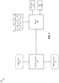
- FIG. 1 depicts a system 100 for scanning an environment according to one or more embodiments described herein.
- the system 100 includes a computing device 110 coupled with a scanner 120, which can be a 3D scanner or another suitable scanner.
- the coupling facilitates wired and/or wireless communication between the computing device 110 and the scanner 120.
- the scanner 120 includes a set of sensors 122.
- the set of sensors 122 can include different types of sensors, such as LIDAR 122A (light detection and ranging), RGB-D camera 122B (red-green-blue-depth), and wide-angle/fisheye camera 122C, and other types of sensors.
- the scanner 120 can also include an inertial measurement unit (IMU) 126 to keep track of a 3D movement and orientation of the scanner 120.
- IMU inertial measurement unit
- the scanner 120 can further include a processor 124 that, in turn, includes one or more processing units.
- the processor 124 controls the measurements performed using the set of sensors 122. In one or more examples, the measurements are performed based on one or more instructions received from the computing device 110.
- the LIDAR sensor 122A is a two-dimensional (2D) scanner that sweeps a line of light in a plane (e.g. a plane horizontal to the floor).
- the scanner 120 is a dynamic machine vision sensor (DMVS) scanner manufactured by FARO ® Technologies, Inc. of Lake Mary, Florida, USA. DMVS scanners are discussed further with reference to FIGS. 11A ⁇ 18.
- the scanner 120 may be that described in commonly owned United States Patent Publication 2018/0321383 entitled Triangulation Scanner having Flat Geometry and Projecting Uncoded Spots, the contents of which are incorporated by reference herein. It should be appreciated that the techniques described herein are not limited to use with DMVS scanners and that other types of 3D scanners can be used.
- the computing device 110 can be a desktop computer, a laptop computer, a tablet computer, a phone, or any other type of computing device that can communicate with the scanner 120.
- the computing device 110 generates a point cloud 130 (e.g., a 3D point cloud) of the environment being scanned by the scanner 120 using the set of sensors 122.
- the point cloud 130 is a set of data points (i.e., a collection of three-dimensional coordinates) that correspond to surfaces of objects in the environment being scanned and/or of the environment itself.
- a display (not shown) displays a live view of the point cloud 130.
- the scanner 120 along with capturing the point cloud 130, is also locating itself within the environment.
- the scanner 120 uses odometry, which includes using data from motion or visual sensors to estimate the change in position of the scanner 120 over time. Odometry is used to estimate the position of the scanner 120 relative to a starting location. This method is sensitive to errors due to the integration of velocity measurements over time to give position estimates, which generally applies to odometry from inertial measurements.
- the scanner 120 estimates its position based only on visual sensors.
- a common task in 3D point cloud analysis is a comparison of 3D measurement data (e.g., the point cloud 130) to reference data 132.
- the reference data 132 can be a computer-aided design (CAD) model or a measurement of a so called “golden part.” From this comparison (between the 3D measurement data (e.g., the point cloud 130) and the reference data 132), information about defects or discrepancies in the measurement data can be extracted. Such defects or discrepancies can indicate a dislocated part, a deformation (e.g., a dent or large scratch), or even a missing part of an object.
- CAD computer-aided design
- a typical 2-sigma noise might be 500 ⁇ m at a 500mm measurement distance.
- sensitivity for finding defects may be less than the 2-sigma noise (e.g., less than 500 ⁇ m such as about 300 ⁇ m).
- one or more embodiments described herein use groups of points (referred to as "clusters") for comparison. That is, the present techniques do not look at individual point-by-point distance comparison but instead work on clusters or groups of data points. Because multiple points (i.e., clusters) are investigated at once, the effect of noise is significantly reduced. Further, one or more embodiments described herein perform region growing to an identified displaced cluster(s). This helps to identify a complete subpart (e.g., a screw, a nut, a pin, etc.) of an object as displaced, which simplifies subsequent analysis of the measurement and highlights the complete displaced object in the data.
- a complete subpart e.g., a screw, a nut, a pin, etc.
- displaced point cloud segments with a sensitivity below typical measurement noise can be detected.
- False positive filtering is also provided. Segmentation of a shifted part can be identified for simplified further processing and analysis. Additionally, data does not need to be smoothed as in conventional approaches, which avoids deformation typically associated with conventional point cloud filtering approaches.
- the embodiments of the present disclosure facilitate improvement to computing technology, and particularly to techniques used for scanning an environment using 3D scanners and then evaluating the scanned data.
- the present techniques evaluate point cloud data generated by a 3D scanner to determine defects and/or displacements of an object.
- defects and/or displacements may not be observable to a human observer because they are too small to detect with the human eye, for example, or cannot be observed in data because the data is noisy to the same or similar order of magnitude as the defect/displacement.
- cluster-based cloud-to-cloud comparisons defects and/or displacements that are otherwise undetectable by human visual inspections or in noisy measurement data can be detected. This improves computing technology and further represents a practical application that facilitates object evaluation.
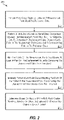
- FIG. 2 depicts a flow diagram of a method 200 for detecting displacements in a point cloud using cluster-based cloud-to-cloud comparison according to one or more embodiments described herein.
- the method 200 can be performed by any suitable processing system or device, such as the computing device 110 for example.
- the computing device 110 performs point cloud alignment between a measurement point cloud and reference data, such as an alignment of the point cloud to a computer-aided-design model or a golden master point cloud for example.
- the computing device 110 performs a multi-scale model-to-model cloud comparison between the measurement point cloud and the reference data to determine a displacement value between each point in the measurement point cloud and a corresponding point in the reference data.
- the computing device 110 filters the points of the measurement point cloud based at least in part on the displacement value by comparing the displacement value to a threshold.
- the computing device 110 iteratively performs multi-radii cluster matching for each of the points of the measurement point cloud having the displacement value greater than the threshold.
- the computing device determines, based on results of the multi-radii cluster matching, whether an object is displaced or whether the object includes a defect.
- FIG. 3 depicts a flow diagram of a method 300 for detecting displacements in a point cloud using cluster-based cloud-to-cloud comparison according to one or more embodiments described herein.
- the method 300 can be performed by any suitable processing system or device, such as the computing device 110 for example.
- the method 300 is now described with respect to FIGS. 3 ⁇ 10.
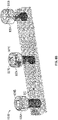
- the method 300 is described with respect to a displaced fastener 410 (e.g. a machine screw) as shown in FIG. 4 .
- FIG. 4 depicts three fasteners: the displaced fastener 410 and non-displaced fasteners 412, 414.
- the displaced fastener 410 is rotated one-half turn less relative to the non-displaced fasteners 412, 414.
- the method 300 enables the computing device 110 to detect that the displaced fastener 410 is displaced by performing cluster-based cloud-to-cloud comparison.
- the computing device 110 receives a point cloud 130 from a scanner 120 (or from another source, such as another scanner or database) and performs point cloud alignment.
- a scanner 120 or from another source, such as another scanner or database
- the computing device 110 aligns and registers both the point clouds for analysis. That is, the computing device 110 aligns and registers the measured point cloud data (e.g., the point cloud 130) with a point cloud generated from a golden part (i.e., the reference data 132).
- each point in the point cloud 130 is associated with a corresponding point in the reference data 132.
- the computing device 110 performs a multiscale model-to-model cloud comparison-based (M3C2) point cloud comparison.
- M3C2 compares the points along the surface normal resulting in a signed distance value.
- FIG. 5 depicts a point cloud 500 of results of applying M3C2 according to one or more embodiments described herein. Each point is colored based on its displacement value (also referred to as an "M3C2 distance") obtained by the M3C2 comparison.
- the computing device 110 performs displaced points filtering.
- the points from the M3C2 at block 304 are compared to a threshold.
- Points with an M3C2 distance greater than the threshold are selected.
- the threshold may be set to 250 ⁇ m. In other examples, other threshold values can be set.
- the points greater than the threshold are then sorted in descending order based on the M3C2 distance to form a displaced points set.
- the point cloud 500 of FIG. 5 includes points above the threshold 501 and points below the threshold 502.
- the computing device 110 performs multi-radii cluster matching. Each point from the displaced points set is used as a test point, and the multi-radii cluster matching is performed on each of those points. For each point (the "test point"), a test cluster is formed by considering the test point's neighbors from the point cloud 130 falling within a radius R. A reference cluster is formed by considering the reference neighbors falling within radius 2 ⁇ R of the point in the reference point cloud (generated from the reference data 132) that is associated with the test point.
- an iterative closest point (ICP) technique is applied to match the points in the test cluster to the points in the reference cluster.
- ICP based cluster matching results in a transformation matrix (for example see transformation matrix 621 in FIG. 6C ).
- the transformation matrix is used to calculate a new displacement value and a displacement vector.
- the M3C2 distance values are updated with the new displacement values.
- the new displacement value is obtained by calculating the centroid of the test cluster points resulting in centroid A.
- the transformation matrix is applied on the test cluster points to calculate the new transformed point's centroid B.
- the difference between centroid A and centroid B yields the displacement vector (for example see displacement vector 622 in FIG. 6C ), and the Euclidean distance between these centroids results in the new displacement value.
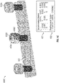
- FIGS. 6A , 6B , 6C , 6D depict point clouds 600A, 600B, 600C, 600D of cluster matching for test clusters for radius values of 250 ⁇ m, 500 ⁇ m, 1000 ⁇ m, and 1500 ⁇ m respectively compared to their associated reference data. Each point is colored or otherwise indicated based on the calculated new distance between test cluster points and reference cluster points.
- cluster matching can be performed with multiple different radius values (such as those shown in FIGS. 6A-6D ). Examples of dislocated regions in the point cloud 130 are shown in FIGS.
- the radius values By selecting the radius values, the potentially displaced regions from the point cloud 130 are collected. Although described as "multi-radii," it should be appreciated that one or more radii may be used. For example, four different radius values, such as those shown in FIGS. 6A-6D , can be used.
- FIG. 6C The transformation matrix 621 and the displacement vector 622 obtained after matching the points in the cluster represented as Region 604C to the reference cluster points are depicted in FIG. 6C .
- displaced points are shown as the points in the Region 611A and non-displaced ("good") points are shown as the points 615.
- the computing device 110 performs extraction of displaced points.
- the displaced points are obtained with more confidence by comparing the points in different radius cluster matching results and removing some of the points that are categorized as displaced because of noise in the data.
- the results obtained from multi-radii cluster matching from block 308 (in this example, done with four different radii values as depicted in FIGS. 6A-6D ) are used to perform this filtering.
- Common displaced points are obtained by comparing two of the multi-radii cluster matching. For example, commonly displaced points are obtained from a first radius (e.g., FIG. 6A ) and a second radius (e.g., FIG. 6B ) cluster matching resulting in Set 1.
- FIG. 7 depicts a point cloud 700 of the extracted displaced points in the displaced fastener example according to one or more embodiments described herein.
- the computing device 110 performs segmentation using region growing segmentation.
- region growing segmentation is performed on the extracted displaced points of the point cloud 700 of FIG. 7 to segment the deformed/dislocated part and calculate its displacement value.
- FIG. 8 depicts a point cloud 800 of extracted displaced points after segmentation according to one or more embodiments described herein.
- each segment group is represented by different shapes as Region 801, Region 802, Region 803, Region 804, and Region 805.
- the region growing segmentation is based on a normal vector for each point. In this embodiment, where there is a smooth transition of the normal vectors, the points are grouped together.
- the computing device 110 performs segment matching.
- ICP is used to match each segment points with a corresponding reference points in the reference data to check if the segment is displaced with respect to the corresponding reference or not. If so, the displacement values for each of the points in the segment is updated using the transformation matrix obtained by segment matching.
- the updated displacement information after segment matching is depicted in FIG. 9 as point cloud 900 where Region 902 is a true-positive segment on which the displacement has been applied and Regions 901, 903, and 904 are false-positive segments.
- False-positive segments are segments classified as displaced and are removed using M3C2 distance filtering and segments point density. For example, M3C2 signed distances values of the points in the segment are determined and the points whose distance value is less than ⁇ 150 ⁇ m are split, resulting in a first set and points whose distance value is greater than ⁇ 150 ⁇ m resulting in a second set. On these new sets (the first set and the second set), the median of the second set's point's M3C2 distance values is calculated. The ratio of the number of points in the first set and the second set is also calculated. Based on these calculations, the segments are then categorized.
- the segments are categorized as true positives.
- sparse false-positive segments are removed if the point density of the segment is less than a threshold limit.
- the final result after applying the segments filter is shown as point cloud 10 in FIG. 10 where displaced points are shown as the points 1001 and non-displaced ("good") points are shown as the points 1002.
- other values besides the median value can be used, such as a mean value, a standard deviation, a median of an absolute distance, etc.
- FIG. 11 it may be desired to capture three-dimensional (3D) measurements of objects.
- the point cloud 130 of FIG. 1 may be captured by the scanner 120.
- One such example of the scanner 120 is now described.
- Such example scanner is referred to as a DVMS scanner by FARO ® .
- a triangulation scanner 1101 includes a body 1105, a projector 1120, a first camera 1130, and a second camera 1140.
- the projector optical axis 1122 of the projector 1120, the first-camera optical axis 1132 of the first camera 1130, and the second-camera optical axis 1142 of the second camera 1140 all lie on a common plane 1150, as shown in FIGS. 11C, 11D .
- an optical axis passes through a center of symmetry of an optical system, which might be a projector or a camera, for example.
- an optical axis may pass through a center of curvature of lens surfaces or mirror surfaces in an optical system.
- the common plane 1150 also referred to as a first plane 1150, extends perpendicular into and out of the paper in FIG. 1D.
- the body 1105 includes a bottom support structure 1106, a top support structure 1107, spacers 1108, camera mounting plates 1109, bottom mounts 1110, dress cover 1111, windows 1112 for the projector and cameras, Ethernet connectors 1113, and GPIO connector 1114.
- the body includes a front side 1115 and a back side 1116.
- the bottom support structure 1106 and the top support structure 1107 are flat plates made of carbon-fiber composite material.
- the carbon-fiber composite material has a low coefficient of thermal expansion (CTE).
- the spacers 1108 are made of aluminum and are sized to provide a common separation between the bottom support structure 1106 and the top support structure 1107.
- the projector 1120 includes a projector body 1124 and a projector front surface 1126.
- the projector 1120 includes a light source 1125 that attaches to the projector body 1124 that includes a turning mirror and a diffractive optical element (DOE), as explained herein below with respect to FIGS. 15A, 15B, 15C .
- the light source 1125 may be a laser, a superluminescent diode, or a partially coherent LED, for example.
- the DOE produces an array of spots arranged in a regular pattern.
- the projector 1120 emits light at a near infrared wavelength.
- the first camera 1130 includes a first-camera body 1134 and a first-camera front surface 36.
- the first camera includes a lens, a photosensitive array, and camera electronics.
- the first camera 1130 forms on the photosensitive array a first image of the uncoded spots projected onto an object by the projector 1120.
- the first camera responds to near infrared light.
- the second camera 1140 includes a second-camera body 1144 and a second-camera front surface 1146.
- the second camera includes a lens, a photosensitive array, and camera electronics.
- the second camera 1140 forms a second image of the uncoded spots projected onto an object by the projector 1120.
- the second camera responds to light in the near infrared spectrum.
- a processor 1102 is used to determine 3D coordinates of points on an object according to methods described herein below.
- the processor 1102 may be included inside the body 1105 or may be external to the body. In further embodiments, more than one processor is used. In still further embodiments, the processor 1102 may be remotely located from the triangulation scanner.
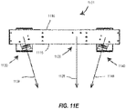
- FIG. 1E is a top view of the triangulation scanner 1101.
- a projector ray 1128 extends along the projector optical axis from the body of the projector 1124 through the projector front surface 1126. In doing so, the projector ray 1128 passes through the front side 1115.
- a first-camera ray 1138 extends along the first-camera optical axis 1132 from the body of the first camera 1134 through the first-camera front surface 1136. In doing so, the front-camera ray 1138 passes through the front side 1115.
- a second-camera ray 1148 extends along the second-camera optical axis 1142 from the body of the second camera 1144 through the second-camera front surface 1146. In doing so, the second-camera ray 1148 passes through the front side 1115.
- FIG. 12A shows elements of a triangulation scanner 1200a that might, for example, be the triangulation scanner 1101 shown in FIGS. 11A, 11B, 11C, 11D , 11E .
- the triangulation scanner 1200a includes a projector 1250, a first camera 1210, and a second camera 1230.
- the projector 1250 creates a pattern of light on a pattern generator plane 1252.
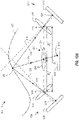
- An exemplary corrected point 1253 on the pattern projects a ray of light 1251 through the perspective center 1258 (point D) of the lens 1254 onto an object surface 1270 at a point 1272 (point F).
- the point 1272 is imaged by the first camera 1210 by receiving a ray of light from the point 1272 through the perspective center 1218 (point E) of the lens 1214 onto the surface of a photosensitive array 1212 of the camera as a corrected point 1220.
- the point 1220 is corrected in the read-out data by applying a correction value to remove the effects of lens aberrations.
- the point 1272 is likewise imaged by the second camera 1230 by receiving a ray of light from the point 1272 through the perspective center 1238 (point C) of the lens 1234 onto the surface of the photosensitive array 1232 of the second camera as a corrected point 1235.
- any reference to a lens includes any type of lens system whether a single lens or multiple lens elements, including an aperture within the lens system.
- any reference to a projector in this document refers not only to a system projecting with a lens or lens system an image plane to an object plane.
- the projector does not necessarily have a physical pattern-generating plane 1252 but may have any other set of elements that generate a pattern.
- the diverging spots of light may be traced backward to obtain a perspective center for the projector and also to obtain a reference projector plane that appears to generate the pattern.
- the projectors described herein propagate uncoded spots of light in an uncoded pattern.
- a projector may further be operable to project coded spots of light, to project in a coded pattern, or to project coded spots of light in a coded pattern.
- the projector is at least operable to project uncoded spots in an uncoded pattern but may in addition project in other coded elements and coded patterns.
- the triangulation scanner 1200a of FIG. 12A is a single-shot scanner that determines 3D coordinates based on a single projection of a projection pattern and a single image captured by each of the two cameras, then a correspondence between the projector point 1253, the image point 1220, and the image point 1235 may be obtained by matching a coded pattern projected by the projector 1250 and received by the two cameras 1210, 1230.
- the coded pattern may be matched for two of the three elements ⁇ for example, the two cameras 1210, 1230 or for the projector 1250 and one of the two cameras 1210 or 1230. This is possible in a single-shot triangulation scanner because of coding in the projected elements or in the projected pattern or both.
- a triangulation calculation is performed to determine 3D coordinates of the projected element on an object.
- the elements are uncoded spots projected in a uncoded pattern.
- a triangulation calculation is performed based on selection of a spot for which correspondence has been obtained on each of two cameras.
- the relative position and orientation of the two cameras is used.
- the baseline distance B3 between the perspective centers 1218 and 1238 is used to perform a triangulation calculation based on the first image of the first camera 1210 and on the second image of the second camera 1230.
- the baseline B1 is used to perform a triangulation calculation based on the projected pattern of the projector 1250 and on the second image of the second camera 1230.
- the baseline B2 is used to perform a triangulation calculation based on the projected pattern of the projector 1250 and on the first image of the first camera 1210.
- the correspondence is determined based at least on an uncoded pattern of uncoded elements projected by the projector, a first image of the uncoded pattern captured by the first camera, and a second image of the uncoded pattern captured by the second camera.
- the correspondence is further based at least in part on a position of the projector, the first camera, and the second camera.
- the correspondence is further based at least in part on an orientation of the projector, the first camera, and the second camera.
- uncoded element or “uncoded spot” as used herein refers to a projected or imaged element that includes no internal structure that enables it to be distinguished from other uncoded elements that are projected or imaged.
- uncoded pattern refers to a pattern in which information is not encoded in the relative positions of projected or imaged elements.
- one method for encoding information into a projected pattern is to project a quasi-random pattern of "dots" in which the relative position of the dots is known ahead of time and can be used to determine correspondence of elements in two images or in a projection and an image.
- Such a quasi-random pattern contains information that may be used to establish correspondence among points and hence is not an example of a uncoded pattern.
- An example of an uncoded pattern is a rectilinear pattern of projected pattern elements.
- uncoded spots are projected in an uncoded pattern as illustrated in the scanner system 12100 of FIG. 12B .
- the scanner system 12100 includes a projector 12110, a first camera 12130, a second camera 12140, and a processor 12150.
- the projector projects an uncoded pattern of uncoded spots off a projector reference plane 12114.
- the uncoded pattern of uncoded spots is a rectilinear array 12111 of circular spots that form illuminated object spots 12121 on the object 12120.
- the rectilinear array of spots 12111 arriving at the object 12120 is modified or distorted into the pattern of illuminated object spots 12121 according to the characteristics of the object 12120.
- An exemplary uncoded spot 12112 from within the projected rectilinear array 12111 is projected onto the object 12120 as a spot 12122.
- the direction from the projector spot 12112 to the illuminated object spot 12122 may be found by drawing a straight line 12124 from the projector spot 12112 on the reference plane 12114 through the projector perspective center 12116.
- the location of the projector perspective center 12116 is determined by the characteristics of the projector optical system.
- the illuminated object spot 12122 produces a first image spot 12134 on the first image plane 12136 of the first camera 12130.
- the direction from the first image spot to the illuminated object spot 12122 may be found by drawing a straight line 12126 from the first image spot 12134 through the first camera perspective center 12132.
- the location of the first camera perspective center 12132 is determined by the characteristics of the first camera optical system.
- the illuminated object spot 12122 produces a second image spot 12144 on the second image plane 12146 of the second camera 12140.
- the direction from the second image spot 12144 to the illuminated object spot 12122 may be found by drawing a straight line 12126 from the second image spot 12144 through the second camera perspective center 12142.
- the location of the second camera perspective center 12142 is determined by the characteristics of the second camera optical system.
- a processor 12150 is in communication with the projector 12110, the first camera 12130, and the second camera 12140. Either wired or wireless channels 12151 may be used to establish connection among the processor 12150, the projector 12110, the first camera 12130, and the second camera 12140.
- the processor may include a single processing unit or multiple processing units and may include components such as microprocessors, field programmable gate arrays (FPGAs), digital signal processors (DSPs), and other electrical components.
- the processor may be local to a scanner system that includes the projector, first camera, and second camera, or it may be distributed and may include networked processors.
- the term processor encompasses any type of computational electronics and may include memory storage elements.
- FIG. 12E shows elements of a method 12180 for determining 3D coordinates of points on an object.
- An element 12182 includes projecting, with a projector, a first uncoded pattern of uncoded spots to form illuminated object spots on an object.
- FIGs. 12B , 12C illustrate this element 12182 using an embodiment 12100 in which a projector 12110 projects a first uncoded pattern of uncoded spots 12111 to form illuminated object spots 12121 on an object 12120.
- a method element 12184 includes capturing with a first camera the illuminated object spots as first-image spots in a first image. This element is illustrated in FIG. 12B using an embodiment in which a first camera 12130 captures illuminated object spots 12121, including the first-image spot 12134, which is an image of the illuminated object spot 12122.
- a method element 12186 includes capturing with a second camera the illuminated object spots as second-image spots in a second image. This element is illustrated in FIG. 12B using an embodiment in which a second camera 140 captures illuminated object spots 12121, including the second-image spot 12144, which is an image of the illuminated object spot 12122.
- a first aspect of method element 12188 includes determining with a processor 3D coordinates of a first collection of points on the object based at least in part on the first uncoded pattern of uncoded spots, the first image, the second image, the relative positions of the projector, the first camera, and the second camera, and a selected plurality of intersection sets. This aspect of the element 12188 is illustrated in FIGs.
- the processor 12150 determines the 3D coordinates of a first collection of points corresponding to object spots 12121 on the object 12120 based at least in the first uncoded pattern of uncoded spots 12111, the first image 12136, the second image 12146, the relative positions of the projector 12110, the first camera 12130, and the second camera 12140, and a selected plurality of intersection sets.
- An example from FIG. 12B of an intersection set is the set that includes the points 12112, 12134, and 12144. Any two of these three points may be used to perform a triangulation calculation to obtain 3D coordinates of the illuminated object spot 12122 as discussed herein above in reference to FIGs. 12A , 12B .
- a second aspect of the method element 12188 includes selecting with the processor a plurality of intersection sets, each intersection set including a first spot, a second spot, and a third spot, the first spot being one of the uncoded spots in the projector reference plane, the second spot being one of the first-image spots, the third spot being one of the second-image spots, the selecting of each intersection set based at least in part on the nearness of intersection of a first line, a second line, and a third line, the first line being a line drawn from the first spot through the projector perspective center, the second line being a line drawn from the second spot through the first-camera perspective center, the third line being a line drawn from the third spot through the second-camera perspective center.
- This aspect of the element 12188 is illustrated in FIG.
- intersection set includes the first spot 12112, the second spot 12134, and the third spot 12144.
- the first line is the line 12124
- the second line is the line 12126
- the third line is the line 12128.
- the first line 12124 is drawn from the uncoded spot 12112 in the projector reference plane 12114 through the projector perspective center 12116.
- the second line 12126 is drawn from the first-image spot 12134 through the first-camera perspective center 12132.
- the third line 12128 is drawn from the second-image spot 12144 through the second-camera perspective center 12142.
- the processor 12150 selects intersection sets based at least in part on the nearness of intersection of the first line 12124, the second line 12126, and the third line 12128.
- the processor 12150 may determine the nearness of intersection of the first line, the second line, and the third line based on any of a variety of criteria.
- the criterion for the nearness of intersection is based on a distance between a first 3D point and a second 3D point.
- the first 3D point is found by performing a triangulation calculation using the first image point 12134 and the second image point 12144, with the baseline distance used in the triangulation calculation being the distance between the perspective centers 12132 and 12142.
- the second 3D point is found by performing a triangulation calculation using the first image point 12134 and the projector point 12112, with the baseline distance used in the triangulation calculation being the distance between the perspective centers 12134 and 12116.
- the criterion for the nearness of the intersection is based on a maximum of closest-approach distances between each of the three pairs of lines. This situation is illustrated in FIG. 12D .
- a line of closest approach 12125 is drawn between the lines 12124 and 12126.
- the line 12125 is perpendicular to each of the lines 12124, 12126 and has a nearness-of-intersection length a.
- a line of closest approach 12127 is drawn between the lines 12126 and 12128.
- the line 12127 is perpendicular to each of the lines 12126, 12128 and has length b.
- a line of closest approach 12129 is drawn between the lines 12124 and 12128.
- the line 12129 is perpendicular to each of the lines 12124, 12128 and has length c.
- the value to be considered is the maximum of a, b, and c.
- a relatively small maximum value would indicate that points 12112, 12134, and 12144 have been correctly selected as corresponding to the illuminated object point 12122.
- a relatively large maximum value would indicate that points 12112, 12134, and 12144 were incorrectly selected as corresponding to the illuminated object point 12122.
- the processor 12150 may use many other criteria to establish the nearness of intersection. For example, for the case in which the three lines were coplanar, a circle inscribed in a triangle formed from the intersecting lines would be expected to have a relatively small radius if the three points 12112, 12134, 12144 corresponded to the object point 12122. For the case in which the three lines were not coplanar, a sphere having tangent points contacting the three lines would be expected to have a relatively small radius.
- intersection sets based at least in part on a nearness of intersection of the first line, the second line, and the third line is not used in most other projector-camera methods based on triangulation.
- the projected points are coded points, which is to say, recognizable as corresponding when compared on projection and image planes, there is no need to determine a nearness of intersection of the projected and imaged elements.
- the method element 12190 includes storing 3D coordinates of the first collection of points.
- a triangulation scanner places a projector and two cameras in a triangular pattern.
- An example of a triangulation scanner 1300 having such a triangular pattern is shown in FIG. 13 .
- the triangulation scanner 1300 includes a projector 1350, a first camera 1310, and a second camera 1330 arranged in a triangle having sides A1-A2-A3.
- the triangulation scanner 1300 may further include an additional camera 1390 not used for triangulation but to assist in registration and colorization.
- the epipolar relationships for a 3D imager (triangulation scanner) 1490 correspond with 3D imager 1300 of FIG. 13 in which two cameras and one projector are arranged in the shape of a triangle having sides 1402, 1404, 1406.
- the device 1, device 2, and device 3 may be any combination of cameras and projectors as long as at least one of the devices is a camera.
- Each of the three devices 1491, 1492, 1493 has a perspective center O1, O2, O3, respectively, and a reference plane 1460, 1470, and 1480, respectively.
- FIG. 14 the epipolar relationships for a 3D imager (triangulation scanner) 1490 correspond with 3D imager 1300 of FIG. 13 in which two cameras and one projector are arranged in the shape of a triangle having sides 1402, 1404, 1406.
- the device 1, device 2, and device 3 may be any combination of cameras and projectors as long as at least one of the devices is a camera.
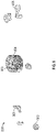
- Each of the three devices 1491, 1492, 1493 has a perspective center O1,
- the reference planes 1460, 1470, 1480 are epipolar planes corresponding to physical planes such as an image plane of a photosensitive array or a projector plane of a projector pattern generator surface but with the planes projected to mathematically equivalent positions opposite the perspective centers O1, O2, O3.
- Each pair of devices has a pair of epipoles, which are points at which lines drawn between perspective centers intersect the epipolar planes.
- Device 1 and device 2 have epipoles E12, E21 on the planes 1460, 1470, respectively.
- Device 1 and device 3 have epipoles E13, E31, respectively on the planes 1460, 1480, respectively.
- Device 2 and device 3 have epipoles E23, E32 on the planes 1470, 1480, respectively.
- each reference plane includes two epipoles.
- the reference plane for device 1 includes epipoles E12 and E13.
- the reference plane for device 2 includes epipoles E21 and E23.
- the reference plane for device 3 includes epipoles E31 and E32.
- the device 3 is a projector 1493
- the device 1 is a first camera 1491
- the device 2 is a second camera 1492.
- a projection point P3, a first image point P1, and a second image point P2 are obtained in a measurement. These results can be checked for consistency in the following way.
- the projection point P3 intersect the plane P2-E23-E32 with the reference plane 1480 to obtain the epipolar line 1484. Intersect the plane P1-E13-E31 to obtain the epipolar line 1482. If the projection point P3 has been determined consistently, the projection point P3 will lie on the intersection of the determined epipolar lines 1482 and 1484.
- the 3D coordinates of the point in the frame of reference of the 3D imager 1490 may be determined using triangulation methods.
- determining self-consistency of the positions of an uncoded spot on the projection plane of the projector and the image planes of the first and second cameras is used to determine correspondence among uncoded spots, as described herein above in reference to FIGS. 12B , 12C , 12D , 12E .
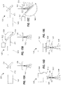
- FIGS. 15A, 15B, 15C, 15D, 15E are schematic illustrations of alternative embodiments of the projector 1120.
- a projector 1500 includes a light source, mirror 1504, and diffractive optical element (DOE) 1506.
- the light source 1502 may be a laser, a superluminescent diode, or a partially coherent LED, for example.
- the light source 1502 emits a beam of light 1510 that reflects off mirror 1504 and passes through the DOE.
- the DOE 11506 produces an array of diverging and uniformly distributed light spots 512.
- a projector 1520 includes the light source 1502, mirror 1504, and DOE 1506 as in FIG. 15A . However, in the projector 1520 of FIG.
- the mirror 1504 is attached to an actuator 1522 that causes rotation 1524 or some other motion (such as translation) in the mirror.
- the reflected beam off the mirror 1504 is redirected or steered to a new position before reaching the DOE 1506 and producing the collection of light spots 1512.
- the actuator is applied to a mirror 1532 that redirects the beam 1512 into a beam 1536.
- Other types of steering mechanisms such as those that employ mechanical, optical, or electro-optical mechanisms may alternatively be employed in the systems of FIGS. 15A, 15B, 15C .
- the light passes first through the pattern generating element 1506 and then through the mirror 1504 or is directed towards the object space without a mirror 1504.
- an electrical signal is provided by the electronics 1544 to drive a projector pattern generator 1542, which may be a pixel display such as a Liquid Crystal on Silicon (LCoS) display to serve as a pattern generator unit, for example.
- the light 1545 from the LCoS display 1542 is directed through the perspective center 1547 from which it emerges as a diverging collection of uncoded spots 1548.
- a source is light 1552 may emit light that may be sent through or reflected off of a pattern generating unit 1554.
- the source of light 1552 sends light to a digital micromirror device (DMD), which reflects the light 1555 through a lens 1556.
- DMD digital micromirror device
- the light is directed through a perspective center 1557 from which it emerges as a diverging collection of uncoded spots 1558 in an uncoded pattern.
- the source of light 1562 passes through a slide 1554 having an uncoded pattern of dots before passing through a lens 1556 and proceeding as an uncoded pattern of light 1558.
- the light from the light source 1552 passes through a lenslet array 1554 before being redirected into the pattern 1558. In this case, inclusion of the lens 1556 is optional.
- the actuators 1522, 1534 may be any of several types such as a piezo actuator, a microelectromechanical system (MEMS) device, a magnetic coil, or a solid-state deflector.
- MEMS microelectromechanical system
- FIG. 16A is an isometric view of a triangulation scanner 1600 that includes a single camera 1602 and two projectors 1604, 1606, these having windows 1603, 1605, 1607, respectively.
- the projected uncoded spots by the projectors 1604, 1606 are distinguished by the camera 1602. This may be the result of a difference in a characteristic in the uncoded projected spots.
- the spots projected by the projector 1604 may be a different color than the spots projected by the projector 1606 if the camera 1602 is a color camera.
- the triangulation scanner 1600 and the object under test are stationary during a measurement, which enables images projected by the projectors 1604, 1606 to be collected sequentially by the camera 1602.
- the system 1600 includes a processor 1102 that carries out computational tasks such as determining correspondence among uncoded spots in projected and image planes and in determining 3D coordinates of the projected spots.
- FIG. 16B is an isometric view of a triangulation scanner 1620 that includes a projector 1622 and in addition includes three cameras: a first camera 1624, a second camera 1626, and a third camera 1628. These aforementioned projector and cameras are covered by windows 1623, 1625, 1627, 1629, respectively.
- a triangulation scanner having three cameras and one projector, it is possible to determine the 3D coordinates of projected spots of uncoded light without knowing in advance the pattern of dots emitted from the projector.
- lines can be drawn from an uncoded spot on an object through the perspective center of each of the three cameras. The drawn lines may each intersect with an uncoded spot on each of the three cameras.
- Triangulation calculations can then be performed to determine the 3D coordinates of points on the object surface.
- the triangulation scanner 1620 includes the processor 1102 that carries out operational methods such as verifying correspondence among uncoded spots in three image planes and in determining 3D coordinates of projected spots on the object.
- FIG. 16C is an isometric view of a triangulation scanner 1640 like that of FIG. 1A except that it further includes a camera 1642, which is coupled to the triangulation scanner 1640.
- the camera 1642 is a color camera that provides colorization to the captured 3D image.
- the camera 1642 assists in registration when the camera 1642 is moved ⁇ for example, when moved by an operator or by a robot.
- FIGS. 17A, 17B illustrate two different embodiments for using the triangulation scanner 1 in an automated environment.
- FIG. 17A illustrates an embodiment in which a scanner 1 is fixed in position and an object under test 1702 is moved, such as on a conveyor belt 1700 or other transport device.
- the scanner 1 obtains 3D coordinates for the object 1702.
- a processor either internal or external to the scanner 1, further determines whether the object 1702 meets its dimensional specifications.
- the scanner 1 is fixed in place, such as in a factory or factory cell for example, and used to monitor activities.
- the processor 1102 monitors whether there is risk of contact with humans from moving equipment in a factory environment and, in response, issue warnings, alarms, or cause equipment to stop moving.
- FIG. 17B illustrates an embodiment in which a triangulation scanner 1 is attached to a robot end effector 1710, which may include a mounting plate 1712 and robot arm 1714.
- the robot may be moved to measure dimensional characteristics of one or more objects under test.
- the robot end effector is replaced by another type of moving structure.
- the triangulation scanner 1101 may be mounted on a moving portion of a machine tool.
- FIG. 18 is a schematic isometric drawing of a measurement application 1800 that may be suited to the triangulation scanners described herein above.
- a triangulation scanner 1101 sends uncoded spots of light onto a sheet of translucent or nearly transparent material 1810 such as glass.
- the uncoded spots of light 1802 on the glass front surface 1812 arrive at an angle to a normal vector of the glass front surface 1812.
- Part of the optical power in the uncoded spots of light 1802 pass through the front surface 1812, are reflected off the back surface 1814 of the glass, and arrive a second time at the front surface 1812 to produce reflected spots of light 1804, represented in FIG. 18 as dashed circles.
- the spots of light 1804 are shifted laterally with respect to the spots of light 1802. If the reflectance of the glass surfaces is relatively high, multiple reflections between the front and back glass surfaces may be picked up by the triangulation scanner 1.
- the uncoded spots of lights 1802 at the front surface 1812 satisfy the criterion described with respect to FIG. 12 in being intersected by lines drawn through perspective centers of the projector and two cameras of the scanner.
- the element 1250 is a projector
- the elements 1210, 1230 are cameras
- the object surface 1270 represents the glass front surface 1270.
- the projector 1250 sends light from a point 1253 through the perspective center 1258 onto the object 1270 at the position 1272.
- Let the point 1253 represent the center of a spot of light 1802 in FIG. 18 .
- the object point 1272 passes through the perspective center 1218 of the first camera onto the first image point 1220.
- the image points 1200, 1235 represent points at the center of the uncoded spots 1802.
- the image points 1200, 1235 represent points at the center of the uncoded spots 1802.
- the spots at the front surface may be distinguished from the spots at the back surface, which is to say that the 3D coordinates of the front surface are determined without contamination by reflections from the back surface. This is possible as long as the thickness of the glass is large enough and the glass is tilted enough relative to normal incidence. Separation of points reflected off front and back glass surfaces is further enhanced by a relatively wide spacing of uncoded spots in the projected uncoded pattern as illustrated in FIG. 18 .
- FIG. 18 was described with respect to the scanner 1, the method would work equally well for other scanner embodiments such as the scanners 1600, 1620, 1640 of FIGS. 16A, 16B, 16C , respectively.
- processor controller, computer, DSP, FPGA are understood in this document to mean a computing device that may be located within an instrument, distributed in multiple elements throughout an instrument, or placed external to an instrument.
Landscapes
- Engineering & Computer Science (AREA)
- Theoretical Computer Science (AREA)
- Physics & Mathematics (AREA)
- General Physics & Mathematics (AREA)
- Computer Vision & Pattern Recognition (AREA)
- Evolutionary Computation (AREA)
- Data Mining & Analysis (AREA)
- General Engineering & Computer Science (AREA)
- Software Systems (AREA)
- Artificial Intelligence (AREA)
- Computer Graphics (AREA)
- Geometry (AREA)
- Computer Hardware Design (AREA)
- Evolutionary Biology (AREA)
- Life Sciences & Earth Sciences (AREA)
- Health & Medical Sciences (AREA)
- Computing Systems (AREA)
- Databases & Information Systems (AREA)
- General Health & Medical Sciences (AREA)
- Medical Informatics (AREA)
- Bioinformatics & Computational Biology (AREA)
- Multimedia (AREA)
- Bioinformatics & Cheminformatics (AREA)
- Architecture (AREA)
- Quality & Reliability (AREA)
- Length Measuring Devices By Optical Means (AREA)
Abstract
Description
- This application claims the benefit of
U.S. Provisional Application Serial No. 63/082,206, filed September 23, 2020 - Embodiments of the present disclosure generally relate to detecting displacements and/or defects in a point cloud and, in particular, to techniques for detecting displacements and/or defects in a point cloud using cluster-based cloud-to-cloud comparison.
- The acquisition of three-dimensional coordinates of an object or an environment is known. Various techniques may be used, such as time-of-flight (TOF) or triangulation methods, for example. A TOF system such as a laser tracker, for example, directs a beam of light such as a laser beam toward a retroreflector target positioned over a spot to be measured. An absolute distance meter (ADM) is used to determine the distance from the distance meter to the retroreflector based on the length of time it takes the light to travel to the spot and return. By moving the retroreflector target over the surface of the object, the coordinates of the object surface may be ascertained. Another example of a TOF system is a laser scanner that measures a distance to a spot on a diffuse surface with an ADM that measures the time for the light to travel to the spot and return. TOF systems have advantages in being accurate, but in some cases may be slower than systems that project a pattern such as a plurality of light spots simultaneously onto the surface at each instant in time.
- In contrast, a triangulation system, such as a scanner, projects either a line of light (e.g., from a laser line probe) or a pattern of light (e.g., from a structured light) onto the surface. In this system, a camera is coupled to a projector in a fixed mechanical relationship. The light/pattern emitted from the projector is reflected off of the surface and detected by the camera. Since the camera and projector are arranged in a fixed relationship, the distance to the object may be determined from captured images using trigonometric principles. Triangulation systems provide advantages in quickly acquiring coordinate data over large areas.
- In some systems, during the scanning process, the scanner acquires, at different times, a series of images of the patterns of light formed on the object surface. These multiple images are then registered relative to each other so that the position and orientation of each image relative to the other images are known. Where the scanner is handheld, various techniques have been used to register the images. One common technique uses features in the images to match overlapping areas of adjacent image frames. This technique works well when the object being measured has many features relative to the field of view of the scanner. However, if the object contains a relatively large flat or curved surface, the images may not properly register relative to each other.
- Accordingly, while existing 3D scanners are suitable for their intended purposes, what is needed is a 3D scanner having certain features of embodiments of the present invention.
- According to one or more examples, a method includes performing cluster matching with one or more cluster sizes for each of a plurality of points of a measurement point cloud. The method further includes determining, based on results of the multi-radii cluster matching, whether an object is displaced or whether the object includes a defect.
- In addition to one or more of the features described herein, or as an alternative, further embodiments of the method may include acquiring, using a three-dimensional scanner, the measurement point cloud.
- In addition to one or more of the features described herein, or as an alternative, further embodiments of the method may include performing segmentation to generate larger clusters of connected regions using region growing segmentation on extracted displaced points.
- In addition to one or more of the features described herein, or as an alternative, further embodiments of the method may include performing false-positive detection to remove one or more false-positive segments.
- In addition to one or more of the features described herein, or as an alternative, further embodiments of the method may include that the false-positive detection is performed based at least in part on a deviation histogram of the points in this cluster.
- In addition to one or more of the features described herein, or as an alternative, further embodiments of the method may include performing a comparison between the measurement point cloud and reference data to determine a displacement value between each point in the measurement point cloud and corresponding point in the reference data.
- In addition to one or more of the features described herein, or as an alternative, further embodiments of the method may include that the reference data is a reference point cloud.
- In addition to one or more of the features described herein, or as an alternative, further embodiments of the method may include that the reference data is a computer-aided design model.
- In addition to one or more of the features described herein, or as an alternative, further embodiments of the method may include that the reference data is scan data of a scanned golden part.
- In addition to one or more of the features described herein, or as an alternative, further embodiments of the method may include that a set of points selected for a cluster is based at least in part on a result of a point-wise distance analysis between the measurement point cloud and the reference data.
- In addition to one or more of the features described herein, or as an alternative, further embodiments of the method may include that performing the comparison comprises performing a multi-scale model-to-model cloud comparison.
- In addition to one or more of the features described herein, or as an alternative, further embodiments of the method may include that performing the cluster matching comprises performing a multi-radii cluster matching.
- In addition to one or more of the features described herein, or as an alternative, further embodiments of the method may include that performing the multi-radii cluster matching comprises determining a first cluster defined by a first radius R1.
- In addition to one or more of the features described herein, or as an alternative, further embodiments of the method may include that performing the multi-radii cluster matching comprises determining a second cluster defined by a second radius R2, wherein the second radius R2 is greater than the first radius R1.
- In addition to one or more of the features described herein, or as an alternative, further embodiments of the method may include that determining, based on results of the multi-radii cluster matching, whether the object is displaced is based on one or more of a mean value, a median value, a standard deviation, or a median of an absolute distance.
- In addition to one or more of the features described herein, or as an alternative, further embodiments of the method may include that performing the multi-radii cluster matching comprises applying an iterative closest point technique to match points in a test cluster with points in a reference cluster.
- In addition to one or more of the features described herein, or as an alternative, further embodiments of the method may include that performing the multi-radii cluster matching comprises generating a transformation matrix.
- In addition to one or more of the features described herein, or as an alternative, further embodiments of the method may include that the transformation matrix is used to calculate a new displacement value.
- In addition to one or more of the features described herein, or as an alternative, further embodiments of the method may include that a distance of a center of mass of the cluster of the reference point cloud and a center of mass of the cluster of the measured point cloud is used to calculate the new displacement vector.
- In addition to one or more of the features described herein, or as an alternative, further embodiments of the method may include that performing the multi-radii cluster matching comprises determining a first cluster defined by a first radius R1, determining a second cluster defined by a second radius R2, determining a third cluster defined by a third radius R3, and determining a fourth cluster defined by a fourth radius R4, wherein the fourth radius R4 is greater than the third radius R3, which is greater than the second radius R2, which is greater than the first radius R1.
- In addition to one or more of the features described herein, or as an alternative, further embodiments of the method may include responsive to determining that the object is displaced, performing validation based at least in part on a displacement of at least one different cluster at a location of interest, where the other clusters incorporate points which are part of a first cluster.
- In addition to one or more of the features described herein, or as an alternative, further embodiments of the method may include performing point cloud alignment between the measurement point cloud and reference data.
- According to one or more examples, a method includes acquiring a measured point cloud of an object using a three-dimensional scanner to scan the object. The method further includes performing a point cloud alignment between the measured point cloud and a reference point cloud. The method further includes performing a multi-scale model-to-model cloud comparison between the measurement point cloud and the reference point. The method further includes performing displaced points filtering. The method further includes performing multi-radii cluster matching. The method further includes performing extraction of displaced points. The method further includes performing segmentation. The method further includes performing segment matching. The method further includes performing segments filtering. The method further includes determining whether the object is displaced.
- The subject matter, which is regarded as the invention, is particularly pointed out and distinctly claimed in the claims at the conclusion of the specification. The foregoing and other features, and advantages of embodiments of the invention are apparent from the following detailed description taken in conjunction with the accompanying drawings in which:
-
FIG. 1 depicts a system for scanning an environment according to one or more embodiments described herein; -
FIG. 2 depicts a flow diagram of a method for detecting displacements in a point cloud using cluster-based cloud-to-cloud comparison according to one or more embodiments described herein; -
FIG. 3 depicts a flow diagram of a method for detecting displacements in a point cloud using cluster-based cloud-to-cloud comparison according to one or more embodiments described herein; -
FIG. 4 depicts an example of three fasteners including a displaced fastener and two non-displaced fasteners that are scanned to generate a point cloud according to one or more embodiments described herein; -
FIG. 5 depicts a point cloud of results of applying multiscale model-to-model cloud comparison-based (M3C2) point cloud comparison according to one or more embodiments described herein; -
FIGS. 6A ,6B ,6C ,6D depict point clouds of cluster matching for test clusters for radius values of 250µm, 500µm, 1000µm, and 1500µm respectively compared to their respective reference data according to one or more embodiments described herein; -
FIG. 7 depicts a point cloud of extracted displaced points according to one or more embodiments described herein; -
FIG. 8 depicts a point cloud of extracted displaced points after segmentation according to one or more embodiments described herein; -
FIG. 9 depicts a point cloud of updated displacement information after segment matching according to one or more embodiments described herein; -
FIG. 10 depicts a point cloud of final results after applying a segments filter according to one or more embodiments described herein; -
FIGS. 11A, 11B, 11C, 11D ,11E are isometric, partial isometric, partial top, partial front, and second partial top views, respectively, of a triangulation scanner according to one or more embodiments described herein; -
FIG. 12A is a schematic view of a triangulation scanner having a projector, a first camera, and a second camera according to one or more embodiments described herein; -
FIG. 12B is a schematic representation of a triangulation scanner having a projector that projects and uncoded pattern of uncoded spots, received by a first camera, and a second camera according to one or more embodiments described herein; -
FIG. 12C is an example of an uncoded pattern of uncoded spots according to one or more embodiments described herein; -
FIG. 12D is a representation of one mathematical method that might be used to determine a nearness of intersection of three lines according to one or more embodiments described herein; -
FIG. 12E is a list of elements in a method for determining 3D coordinates of an object according to one or more embodiments described herein; -
FIG. 13 is an isometric view of a triangulation scanner having a projector and two cameras arranged in a triangle according to one or more embodiments described herein; -
FIG. 14 is a schematic illustration of intersecting epipolar lines in epipolar planes for a combination of projectors and cameras according to one or more embodiments described herein; -
FIGS. 15A, 15B, 15C, 15D, 15E are schematic diagrams illustrating different types of projectors according to one or more embodiments described herein; -
FIG. 16A is an isometric view of a triangulation scanner having two projectors and one camera according to one or more embodiments described herein; -
FIG. 16B is an isometric view of a triangulation scanner having three cameras and one projector according to one or more embodiments described herein; -
FIG. 16C is an isometric view of a triangulation scanner having one projector and two cameras and further including a camera to assist in registration or colorization according to one or more embodiments described herein; -
FIG. 17A illustrates a triangulation scanner used to measure an object moving on a conveyor belt according to one or more embodiments described herein; -
FIG. 17B illustrates a triangulation scanner moved by a robot end effector, according to one or more embodiments described herein; and -
FIG. 18 illustrates front and back reflections off a relatively transparent material such as glass according to one or more embodiments described herein. - The technical solutions described herein generally relate to detecting displacements in a point cloud using cluster-based cloud-to-cloud comparison. Point clouds can be captured by a three-dimensional (3D) scanning device or "scanner" as depicted in
FIG. 1 . - In particular,
FIG. 1 depicts asystem 100 for scanning an environment according to one or more embodiments described herein. Thesystem 100 includes acomputing device 110 coupled with ascanner 120, which can be a 3D scanner or another suitable scanner. The coupling facilitates wired and/or wireless communication between thecomputing device 110 and thescanner 120. Thescanner 120 includes a set ofsensors 122. The set ofsensors 122 can include different types of sensors, such as LIDAR 122A (light detection and ranging), RGB-D camera 122B (red-green-blue-depth), and wide-angle/fisheye camera 122C, and other types of sensors. Thescanner 120 can also include an inertial measurement unit (IMU) 126 to keep track of a 3D movement and orientation of thescanner 120. Thescanner 120 can further include aprocessor 124 that, in turn, includes one or more processing units. Theprocessor 124 controls the measurements performed using the set ofsensors 122. In one or more examples, the measurements are performed based on one or more instructions received from thecomputing device 110. In an embodiment, the LIDAR sensor 122A is a two-dimensional (2D) scanner that sweeps a line of light in a plane (e.g. a plane horizontal to the floor). - According to one or more embodiments described herein, the
scanner 120 is a dynamic machine vision sensor (DMVS) scanner manufactured by FARO® Technologies, Inc. of Lake Mary, Florida, USA. DMVS scanners are discussed further with reference toFIGS. 11A ―18. In an embodiment, thescanner 120 may be that described in commonly ownedUnited States Patent Publication 2018/0321383 entitled Triangulation Scanner having Flat Geometry and Projecting Uncoded Spots, the contents of which are incorporated by reference herein. It should be appreciated that the techniques described herein are not limited to use with DMVS scanners and that other types of 3D scanners can be used. - The
computing device 110 can be a desktop computer, a laptop computer, a tablet computer, a phone, or any other type of computing device that can communicate with thescanner 120. - In one or more embodiments, the
computing device 110 generates a point cloud 130 (e.g., a 3D point cloud) of the environment being scanned by thescanner 120 using the set ofsensors 122. Thepoint cloud 130 is a set of data points (i.e., a collection of three-dimensional coordinates) that correspond to surfaces of objects in the environment being scanned and/or of the environment itself. According to one or more embodiments described herein, a display (not shown) displays a live view of thepoint cloud 130. - As noted earlier, the
scanner 120, along with capturing thepoint cloud 130, is also locating itself within the environment. In an embodiment, thescanner 120 uses odometry, which includes using data from motion or visual sensors to estimate the change in position of thescanner 120 over time. Odometry is used to estimate the position of thescanner 120 relative to a starting location. This method is sensitive to errors due to the integration of velocity measurements over time to give position estimates, which generally applies to odometry from inertial measurements. In other embodiments, thescanner 120 estimates its position based only on visual sensors. - A common task in 3D point cloud analysis is a comparison of 3D measurement data (e.g., the point cloud 130) to
reference data 132. Thereference data 132 can be a computer-aided design (CAD) model or a measurement of a so called "golden part." From this comparison (between the 3D measurement data (e.g., the point cloud 130) and the reference data 132), information about defects or discrepancies in the measurement data can be extracted. Such defects or discrepancies can indicate a dislocated part, a deformation (e.g., a dent or large scratch), or even a missing part of an object. - Although some techniques exist for performing basic point cloud-to-point cloud (or "cloud-to-cloud") comparison and/or point cloud-to-CAD model comparison, these approaches operate by comparing single points. Further, such approaches are susceptible to noise in the measurement data. When the measurement data is noisy (i.e., the noise is comparable to the expected/needed sensitivity in the comparison), false-positive detections are likely to be frequent while a high number of true defects go undetected.
- Further, even a visual appearance of a bare cloud-to-cloud comparison is insufficient. The typical result for such visual inspection is the display of the point cloud where each point is colored or otherwise indicated based on its estimated distance to a corresponding reference point in the reference data. In the case of high noise, many points are determined to have a large distance. Hence, the display in the described manner is also noisy, and displacements of small features are undetectable by visual inspection.
- For DMVS scanners, a typical 2-sigma noise might be 500µm at a 500mm measurement distance. In some applications, sensitivity for finding defects may be less than the 2-sigma noise (e.g., less than 500µm such as about 300µm).
- Although some conventional approaches attempt to apply point cloud filters to mitigate noise, these approaches alter the actual measured data. This causes edges and other high frequency features to be deformed after smoothing.
- To address these and other shortcomings of the prior art, one or more embodiments described herein use groups of points (referred to as "clusters") for comparison. That is, the present techniques do not look at individual point-by-point distance comparison but instead work on clusters or groups of data points. Because multiple points (i.e., clusters) are investigated at once, the effect of noise is significantly reduced. Further, one or more embodiments described herein perform region growing to an identified displaced cluster(s). This helps to identify a complete subpart (e.g., a screw, a nut, a pin, etc.) of an object as displaced, which simplifies subsequent analysis of the measurement and highlights the complete displaced object in the data.
- The one or more embodiments described herein provide numerous technical advantages over the prior art. For example, displaced point cloud segments with a sensitivity below typical measurement noise can be detected. False positive filtering is also provided. Segmentation of a shifted part can be identified for simplified further processing and analysis. Additionally, data does not need to be smoothed as in conventional approaches, which avoids deformation typically associated with conventional point cloud filtering approaches.
- The embodiments of the present disclosure, facilitate improvement to computing technology, and particularly to techniques used for scanning an environment using 3D scanners and then evaluating the scanned data. For example, the present techniques evaluate point cloud data generated by a 3D scanner to determine defects and/or displacements of an object. Such defects and/or displacements may not be observable to a human observer because they are too small to detect with the human eye, for example, or cannot be observed in data because the data is noisy to the same or similar order of magnitude as the defect/displacement. By performing cluster-based cloud-to-cloud comparisons, defects and/or displacements that are otherwise undetectable by human visual inspections or in noisy measurement data can be detected. This improves computing technology and further represents a practical application that facilitates object evaluation.
-
FIG. 2 depicts a flow diagram of amethod 200 for detecting displacements in a point cloud using cluster-based cloud-to-cloud comparison according to one or more embodiments described herein. Themethod 200 can be performed by any suitable processing system or device, such as thecomputing device 110 for example. - At
block 202, thecomputing device 110 performs point cloud alignment between a measurement point cloud and reference data, such as an alignment of the point cloud to a computer-aided-design model or a golden master point cloud for example. Atblock 204, thecomputing device 110 performs a multi-scale model-to-model cloud comparison between the measurement point cloud and the reference data to determine a displacement value between each point in the measurement point cloud and a corresponding point in the reference data. Atblock 206, thecomputing device 110 filters the points of the measurement point cloud based at least in part on the displacement value by comparing the displacement value to a threshold. Atblock 208, thecomputing device 110 iteratively performs multi-radii cluster matching for each of the points of the measurement point cloud having the displacement value greater than the threshold. Atblock 210, the computing device determines, based on results of the multi-radii cluster matching, whether an object is displaced or whether the object includes a defect. - Additional processes also may be included, and it should be understood that the process depicted in
FIG. 2 represents an illustration, and that other processes may be added or existing processes may be removed, modified, or rearranged without departing from the scope of the present disclosure. -
FIG. 3 depicts a flow diagram of amethod 300 for detecting displacements in a point cloud using cluster-based cloud-to-cloud comparison according to one or more embodiments described herein. Themethod 300 can be performed by any suitable processing system or device, such as thecomputing device 110 for example. Themethod 300 is now described with respect toFIGS. 3 ―10. As an example, themethod 300 is described with respect to a displaced fastener 410 (e.g. a machine screw) as shown inFIG. 4 . Particularly,FIG. 4 depicts three fasteners: the displacedfastener 410 andnon-displaced fasteners fastener 410 is rotated one-half turn less relative to thenon-displaced fasteners method 300 enables thecomputing device 110 to detect that the displacedfastener 410 is displaced by performing cluster-based cloud-to-cloud comparison. - At
block 302, thecomputing device 110 receives apoint cloud 130 from a scanner 120 (or from another source, such as another scanner or database) and performs point cloud alignment. Given the point cloud data of a golden part (i.e., the reference data 132), which acts as ground truth, and a scan data (e.g., the point cloud 130) captured about a test part (i.e., the displacedfastener 410 and thenon-displaced fasteners 412, 414), thecomputing device 110 aligns and registers both the point clouds for analysis. That is, thecomputing device 110 aligns and registers the measured point cloud data (e.g., the point cloud 130) with a point cloud generated from a golden part (i.e., the reference data 132). As a result, each point in thepoint cloud 130 is associated with a corresponding point in thereference data 132. - At
block 304, thecomputing device 110 performs a multiscale model-to-model cloud comparison-based (M3C2) point cloud comparison. M3C2 compares the points along the surface normal resulting in a signed distance value. The result after applying M3C2 comparison is shown inFIG. 5 . In particular,FIG. 5 depicts apoint cloud 500 of results of applying M3C2 according to one or more embodiments described herein. Each point is colored based on its displacement value (also referred to as an "M3C2 distance") obtained by the M3C2 comparison. - At
block 306, thecomputing device 110 performs displaced points filtering. To do this, the points from the M3C2 atblock 304 are compared to a threshold. Points with an M3C2 distance greater than the threshold are selected. For an example using a DMVS scanner, the threshold may be set to 250µm. In other examples, other threshold values can be set. The points greater than the threshold are then sorted in descending order based on the M3C2 distance to form a displaced points set. Thepoint cloud 500 ofFIG. 5 includes points above thethreshold 501 and points below thethreshold 502. - At
block 308, thecomputing device 110 performs multi-radii cluster matching. Each point from the displaced points set is used as a test point, and the multi-radii cluster matching is performed on each of those points. For each point (the "test point"), a test cluster is formed by considering the test point's neighbors from thepoint cloud 130 falling within a radius R. A reference cluster is formed by considering the reference neighbors falling within radius 2∗R of the point in the reference point cloud (generated from the reference data 132) that is associated with the test point. - Then, an iterative closest point (ICP) technique is applied to match the points in the test cluster to the points in the reference cluster. ICP based cluster matching results in a transformation matrix (for example see
transformation matrix 621 inFIG. 6C ). The transformation matrix is used to calculate a new displacement value and a displacement vector. Then, the M3C2 distance values are updated with the new displacement values. The new displacement value is obtained by calculating the centroid of the test cluster points resulting in centroid A. Then, the transformation matrix is applied on the test cluster points to calculate the new transformed point's centroid B. The difference between centroid A and centroid B yields the displacement vector (for example seedisplacement vector 622 inFIG. 6C ), and the Euclidean distance between these centroids results in the new displacement value. - According to one or more embodiments described herein,
FIGS. 6A ,6B ,6C ,6D depictpoint clouds point cloud 130, cluster matching can be performed with multiple different radius values (such as those shown inFIGS. 6A-6D ). Examples of dislocated regions in thepoint cloud 130 are shown inFIGS. 6A-6D asRegion 601A,Region 601B,Region 602A,Region 603A,Region 603B,Region 604A,Region 604B,Region 605A,Region 606A,Region 606B,Region 607A,Region 607B,Region 607C,Region 608A,Region 608B,Region 609A,Region 609B,Region 609C,Region 610A, andRegion 611A. By selecting the radius values, the potentially displaced regions from thepoint cloud 130 are collected. Although described as "multi-radii," it should be appreciated that one or more radii may be used. For example, four different radius values, such as those shown inFIGS. 6A-6D , can be used. However, in other examples, other numbers of radius values can be used (e.g., 1 radius value, 2 radius values, 3 radius values, 4 radius values, 5 radius values, 6 radius values, etc.). Thetransformation matrix 621 and thedisplacement vector 622 obtained after matching the points in the cluster represented as Region 604C to the reference cluster points are depicted inFIG. 6C . InFIG. 6D , displaced points are shown as the points in theRegion 611A and non-displaced ("good") points are shown as thepoints 615. - At
block 310, thecomputing device 110 performs extraction of displaced points. Here the displaced points are obtained with more confidence by comparing the points in different radius cluster matching results and removing some of the points that are categorized as displaced because of noise in the data. The results obtained from multi-radii cluster matching from block 308 (in this example, done with four different radii values as depicted inFIGS. 6A-6D ) are used to perform this filtering. Common displaced points are obtained by comparing two of the multi-radii cluster matching. For example, commonly displaced points are obtained from a first radius (e.g.,FIG. 6A ) and a second radius (e.g.,FIG. 6B ) cluster matching resulting inSet 1. Similarly, common displaced points are obtained from a third radius (e.g.,FIG. 6C ) and a fourth radius (FIG. 6D ) cluster matching resulting inSet 2. Then, Set 1 andSet 2 are combined as shown inFIG. 7 . In particular,FIG. 7 depicts apoint cloud 700 of the extracted displaced points in the displaced fastener example according to one or more embodiments described herein. - At
block 312, thecomputing device 110 performs segmentation using region growing segmentation. Particularly, region growing segmentation is performed on the extracted displaced points of thepoint cloud 700 ofFIG. 7 to segment the deformed/dislocated part and calculate its displacement value.FIG. 8 depicts apoint cloud 800 of extracted displaced points after segmentation according to one or more embodiments described herein. InFIG. 8 , each segment group is represented by different shapes asRegion 801,Region 802,Region 803,Region 804, andRegion 805. In an embodiment, the region growing segmentation is based on a normal vector for each point. In this embodiment, where there is a smooth transition of the normal vectors, the points are grouped together. - At
block 314, thecomputing device 110 performs segment matching. On the obtained segmented regions, ICP is used to match each segment points with a corresponding reference points in the reference data to check if the segment is displaced with respect to the corresponding reference or not. If so, the displacement values for each of the points in the segment is updated using the transformation matrix obtained by segment matching. The updated displacement information after segment matching is depicted inFIG. 9 aspoint cloud 900 whereRegion 902 is a true-positive segment on which the displacement has been applied andRegions - After segment matching at
block 314, thecomputing device 110 atblock 316 performs segments filtering to remove false-positive segments. False-positive segments are segments classified as displaced and are removed using M3C2 distance filtering and segments point density. For example, M3C2 signed distances values of the points in the segment are determined and the points whose distance value is less than ± 150µm are split, resulting in a first set and points whose distance value is greater than ± 150µm resulting in a second set. On these new sets (the first set and the second set), the median of the second set's point's M3C2 distance values is calculated. The ratio of the number of points in the first set and the second set is also calculated. Based on these calculations, the segments are then categorized. As an example, if the ratio is less than 2 and the median value is greater than 250µm, then the segments are categorized as true positives. In some examples, sparse false-positive segments are removed if the point density of the segment is less than a threshold limit. The final result after applying the segments filter is shown aspoint cloud 10 inFIG. 10 where displaced points are shown as thepoints 1001 and non-displaced ("good") points are shown as thepoints 1002. In some examples, other values besides the median value can be used, such as a mean value, a standard deviation, a median of an absolute distance, etc. - Additional processes also may be included, and it should be understood that the process depicted in
FIG. 3 represents an illustration, and that other processes may be added or existing processes may be removed, modified, or rearranged without departing from the scope of the present disclosure. - Turning now to
FIG. 11 , it may be desired to capture three-dimensional (3D) measurements of objects. For example, thepoint cloud 130 ofFIG. 1 may be captured by thescanner 120. One such example of thescanner 120 is now described. Such example scanner is referred to as a DVMS scanner by FARO®. - In an embodiment illustrated in
FIGS. 11A, 11B, 11C, 11D , atriangulation scanner 1101 includes abody 1105, aprojector 1120, afirst camera 1130, and asecond camera 1140. In an embodiment, the projectoroptical axis 1122 of theprojector 1120, the first-cameraoptical axis 1132 of thefirst camera 1130, and the second-cameraoptical axis 1142 of thesecond camera 1140 all lie on acommon plane 1150, as shown inFIGS. 11C, 11D . In some embodiments, an optical axis passes through a center of symmetry of an optical system, which might be a projector or a camera, for example. For example, an optical axis may pass through a center of curvature of lens surfaces or mirror surfaces in an optical system. Thecommon plane 1150, also referred to as afirst plane 1150, extends perpendicular into and out of the paper in FIG. 1D. - In an embodiment, the
body 1105 includes a bottom support structure 1106, atop support structure 1107,spacers 1108,camera mounting plates 1109, bottom mounts 1110,dress cover 1111,windows 1112 for the projector and cameras,Ethernet connectors 1113, andGPIO connector 1114. In addition, the body includes afront side 1115 and aback side 1116. In an embodiment, the bottom support structure 1106 and thetop support structure 1107 are flat plates made of carbon-fiber composite material. In an embodiment, the carbon-fiber composite material has a low coefficient of thermal expansion (CTE). In an embodiment, thespacers 1108 are made of aluminum and are sized to provide a common separation between the bottom support structure 1106 and thetop support structure 1107. - In an embodiment, the
projector 1120 includes aprojector body 1124 and aprojector front surface 1126. In an embodiment, theprojector 1120 includes alight source 1125 that attaches to theprojector body 1124 that includes a turning mirror and a diffractive optical element (DOE), as explained herein below with respect toFIGS. 15A, 15B, 15C . Thelight source 1125 may be a laser, a superluminescent diode, or a partially coherent LED, for example. In an embodiment, the DOE produces an array of spots arranged in a regular pattern. In an embodiment, theprojector 1120 emits light at a near infrared wavelength. - In an embodiment, the
first camera 1130 includes a first-camera body 1134 and a first-camera front surface 36. In an embodiment, the first camera includes a lens, a photosensitive array, and camera electronics. Thefirst camera 1130 forms on the photosensitive array a first image of the uncoded spots projected onto an object by theprojector 1120. In an embodiment, the first camera responds to near infrared light. - In an embodiment, the
second camera 1140 includes a second-camera body 1144 and a second-camera front surface 1146. In an embodiment, the second camera includes a lens, a photosensitive array, and camera electronics. Thesecond camera 1140 forms a second image of the uncoded spots projected onto an object by theprojector 1120. In an embodiment, the second camera responds to light in the near infrared spectrum. In an embodiment, aprocessor 1102 is used to determine 3D coordinates of points on an object according to methods described herein below. Theprocessor 1102 may be included inside thebody 1105 or may be external to the body. In further embodiments, more than one processor is used. In still further embodiments, theprocessor 1102 may be remotely located from the triangulation scanner. - FIG. 1E is a top view of the
triangulation scanner 1101. Aprojector ray 1128 extends along the projector optical axis from the body of theprojector 1124 through theprojector front surface 1126. In doing so, theprojector ray 1128 passes through thefront side 1115. A first-camera ray 1138 extends along the first-cameraoptical axis 1132 from the body of thefirst camera 1134 through the first-camera front surface 1136. In doing so, the front-camera ray 1138 passes through thefront side 1115. A second-camera ray 1148 extends along the second-cameraoptical axis 1142 from the body of thesecond camera 1144 through the second-camera front surface 1146. In doing so, the second-camera ray 1148 passes through thefront side 1115. -
FIG. 12A shows elements of atriangulation scanner 1200a that might, for example, be thetriangulation scanner 1101 shown inFIGS. 11A, 11B, 11C, 11D ,11E . In an embodiment, thetriangulation scanner 1200a includes aprojector 1250, afirst camera 1210, and asecond camera 1230. In an embodiment, theprojector 1250 creates a pattern of light on apattern generator plane 1252. An exemplary correctedpoint 1253 on the pattern projects a ray of light 1251 through the perspective center 1258 (point D) of thelens 1254 onto anobject surface 1270 at a point 1272 (point F). Thepoint 1272 is imaged by thefirst camera 1210 by receiving a ray of light from thepoint 1272 through the perspective center 1218 (point E) of thelens 1214 onto the surface of aphotosensitive array 1212 of the camera as a correctedpoint 1220. Thepoint 1220 is corrected in the read-out data by applying a correction value to remove the effects of lens aberrations. Thepoint 1272 is likewise imaged by thesecond camera 1230 by receiving a ray of light from thepoint 1272 through the perspective center 1238 (point C) of thelens 1234 onto the surface of thephotosensitive array 1232 of the second camera as a correctedpoint 1235. It should be understood that as used herein any reference to a lens includes any type of lens system whether a single lens or multiple lens elements, including an aperture within the lens system. It should be understood that any reference to a projector in this document refers not only to a system projecting with a lens or lens system an image plane to an object plane. The projector does not necessarily have a physical pattern-generatingplane 1252 but may have any other set of elements that generate a pattern. For example, in a projector having a DOE, the diverging spots of light may be traced backward to obtain a perspective center for the projector and also to obtain a reference projector plane that appears to generate the pattern. In most cases, the projectors described herein propagate uncoded spots of light in an uncoded pattern. However, a projector may further be operable to project coded spots of light, to project in a coded pattern, or to project coded spots of light in a coded pattern. In other words, in some aspects of the disclosed embodiments, the projector is at least operable to project uncoded spots in an uncoded pattern but may in addition project in other coded elements and coded patterns. - In an embodiment where the
triangulation scanner 1200a ofFIG. 12A is a single-shot scanner that determines 3D coordinates based on a single projection of a projection pattern and a single image captured by each of the two cameras, then a correspondence between theprojector point 1253, theimage point 1220, and theimage point 1235 may be obtained by matching a coded pattern projected by theprojector 1250 and received by the twocameras cameras projector 1250 and one of the twocameras - After a correspondence is determined among projected and imaged elements, a triangulation calculation is performed to determine 3D coordinates of the projected element on an object. For
FIG. 12A , the elements are uncoded spots projected in a uncoded pattern. In an embodiment, a triangulation calculation is performed based on selection of a spot for which correspondence has been obtained on each of two cameras. In this embodiment, the relative position and orientation of the two cameras is used. For example, the baseline distance B3 between theperspective centers first camera 1210 and on the second image of thesecond camera 1230. Likewise, the baseline B1 is used to perform a triangulation calculation based on the projected pattern of theprojector 1250 and on the second image of thesecond camera 1230. Similarly, the baseline B2 is used to perform a triangulation calculation based on the projected pattern of theprojector 1250 and on the first image of thefirst camera 1210. In an embodiment, the correspondence is determined based at least on an uncoded pattern of uncoded elements projected by the projector, a first image of the uncoded pattern captured by the first camera, and a second image of the uncoded pattern captured by the second camera. In an embodiment, the correspondence is further based at least in part on a position of the projector, the first camera, and the second camera. In a further embodiment, the correspondence is further based at least in part on an orientation of the projector, the first camera, and the second camera. - The term "uncoded element" or "uncoded spot" as used herein refers to a projected or imaged element that includes no internal structure that enables it to be distinguished from other uncoded elements that are projected or imaged. The term "uncoded pattern" as used herein refers to a pattern in which information is not encoded in the relative positions of projected or imaged elements. For example, one method for encoding information into a projected pattern is to project a quasi-random pattern of "dots" in which the relative position of the dots is known ahead of time and can be used to determine correspondence of elements in two images or in a projection and an image. Such a quasi-random pattern contains information that may be used to establish correspondence among points and hence is not an example of a uncoded pattern. An example of an uncoded pattern is a rectilinear pattern of projected pattern elements.
- In an embodiment, uncoded spots are projected in an uncoded pattern as illustrated in the scanner system 12100 of
FIG. 12B . In an embodiment, the scanner system 12100 includes aprojector 12110, afirst camera 12130, asecond camera 12140, and aprocessor 12150. The projector projects an uncoded pattern of uncoded spots off aprojector reference plane 12114. In an embodiment illustrated inFIGs. 12B and12C , the uncoded pattern of uncoded spots is arectilinear array 12111 of circular spots that form illuminated object spots 12121 on theobject 12120. In an embodiment, the rectilinear array ofspots 12111 arriving at theobject 12120 is modified or distorted into the pattern of illuminated object spots 12121 according to the characteristics of theobject 12120. An exemplaryuncoded spot 12112 from within the projectedrectilinear array 12111 is projected onto theobject 12120 as aspot 12122. The direction from theprojector spot 12112 to the illuminatedobject spot 12122 may be found by drawing astraight line 12124 from theprojector spot 12112 on thereference plane 12114 through theprojector perspective center 12116. The location of theprojector perspective center 12116 is determined by the characteristics of the projector optical system. - In an embodiment, the illuminated
object spot 12122 produces a first image spot 12134 on thefirst image plane 12136 of thefirst camera 12130. The direction from the first image spot to the illuminatedobject spot 12122 may be found by drawing astraight line 12126 from the first image spot 12134 through the firstcamera perspective center 12132. The location of the firstcamera perspective center 12132 is determined by the characteristics of the first camera optical system. - In an embodiment, the illuminated
object spot 12122 produces asecond image spot 12144 on thesecond image plane 12146 of thesecond camera 12140. The direction from thesecond image spot 12144 to the illuminatedobject spot 12122 may be found by drawing astraight line 12126 from thesecond image spot 12144 through the secondcamera perspective center 12142. The location of the secondcamera perspective center 12142 is determined by the characteristics of the second camera optical system. - In an embodiment, a
processor 12150 is in communication with theprojector 12110, thefirst camera 12130, and thesecond camera 12140. Either wired orwireless channels 12151 may be used to establish connection among theprocessor 12150, theprojector 12110, thefirst camera 12130, and thesecond camera 12140. The processor may include a single processing unit or multiple processing units and may include components such as microprocessors, field programmable gate arrays (FPGAs), digital signal processors (DSPs), and other electrical components. The processor may be local to a scanner system that includes the projector, first camera, and second camera, or it may be distributed and may include networked processors. The term processor encompasses any type of computational electronics and may include memory storage elements. -
FIG. 12E shows elements of amethod 12180 for determining 3D coordinates of points on an object. Anelement 12182 includes projecting, with a projector, a first uncoded pattern of uncoded spots to form illuminated object spots on an object.FIGs. 12B ,12C illustrate thiselement 12182 using an embodiment 12100 in which aprojector 12110 projects a first uncoded pattern ofuncoded spots 12111 to form illuminated object spots 12121 on anobject 12120. - A
method element 12184 includes capturing with a first camera the illuminated object spots as first-image spots in a first image. This element is illustrated inFIG. 12B using an embodiment in which afirst camera 12130 captures illuminated object spots 12121, including the first-image spot 12134, which is an image of the illuminatedobject spot 12122. Amethod element 12186 includes capturing with a second camera the illuminated object spots as second-image spots in a second image. This element is illustrated inFIG. 12B using an embodiment in which a second camera 140 captures illuminated object spots 12121, including the second-image spot 12144, which is an image of the illuminatedobject spot 12122. - A first aspect of
method element 12188 includes determining with aprocessor 3D coordinates of a first collection of points on the object based at least in part on the first uncoded pattern of uncoded spots, the first image, the second image, the relative positions of the projector, the first camera, and the second camera, and a selected plurality of intersection sets. This aspect of theelement 12188 is illustrated inFIGs. 12B ,12C using an embodiment in which theprocessor 12150 determines the 3D coordinates of a first collection of points corresponding to objectspots 12121 on theobject 12120 based at least in the first uncoded pattern ofuncoded spots 12111, thefirst image 12136, thesecond image 12146, the relative positions of theprojector 12110, thefirst camera 12130, and thesecond camera 12140, and a selected plurality of intersection sets. An example fromFIG. 12B of an intersection set is the set that includes thepoints object spot 12122 as discussed herein above in reference toFIGs. 12A ,12B . - A second aspect of the
method element 12188 includes selecting with the processor a plurality of intersection sets, each intersection set including a first spot, a second spot, and a third spot, the first spot being one of the uncoded spots in the projector reference plane, the second spot being one of the first-image spots, the third spot being one of the second-image spots, the selecting of each intersection set based at least in part on the nearness of intersection of a first line, a second line, and a third line, the first line being a line drawn from the first spot through the projector perspective center, the second line being a line drawn from the second spot through the first-camera perspective center, the third line being a line drawn from the third spot through the second-camera perspective center. This aspect of theelement 12188 is illustrated inFIG. 12B using an embodiment in which one intersection set includes thefirst spot 12112, the second spot 12134, and thethird spot 12144. In this embodiment, the first line is theline 12124, the second line is theline 12126, and the third line is theline 12128. Thefirst line 12124 is drawn from theuncoded spot 12112 in theprojector reference plane 12114 through theprojector perspective center 12116. Thesecond line 12126 is drawn from the first-image spot 12134 through the first-camera perspective center 12132. Thethird line 12128 is drawn from the second-image spot 12144 through the second-camera perspective center 12142. Theprocessor 12150 selects intersection sets based at least in part on the nearness of intersection of thefirst line 12124, thesecond line 12126, and thethird line 12128. - The
processor 12150 may determine the nearness of intersection of the first line, the second line, and the third line based on any of a variety of criteria. For example, in an embodiment, the criterion for the nearness of intersection is based on a distance between a first 3D point and a second 3D point. In an embodiment, the first 3D point is found by performing a triangulation calculation using the first image point 12134 and thesecond image point 12144, with the baseline distance used in the triangulation calculation being the distance between the perspective centers 12132 and 12142. In the embodiment, the second 3D point is found by performing a triangulation calculation using the first image point 12134 and theprojector point 12112, with the baseline distance used in the triangulation calculation being the distance between the perspective centers 12134 and 12116. If the threelines object point 12122, then the calculation of the distance between the first 3D point and the second 3D point will result in a relatively small distance. On the other hand, a relatively large distance between the first 3D point and the second 3D would indicate that thepoints object point 12122. - As another example, in an embodiment, the criterion for the nearness of the intersection is based on a maximum of closest-approach distances between each of the three pairs of lines. This situation is illustrated in
FIG. 12D . A line ofclosest approach 12125 is drawn between thelines line 12125 is perpendicular to each of thelines closest approach 12127 is drawn between thelines line 12127 is perpendicular to each of thelines closest approach 12129 is drawn between thelines line 12129 is perpendicular to each of thelines points object point 12122. A relatively large maximum value would indicate thatpoints object point 12122. - The
processor 12150 may use many other criteria to establish the nearness of intersection. For example, for the case in which the three lines were coplanar, a circle inscribed in a triangle formed from the intersecting lines would be expected to have a relatively small radius if the threepoints object point 12122. For the case in which the three lines were not coplanar, a sphere having tangent points contacting the three lines would be expected to have a relatively small radius. - It should be noted that the selecting of intersection sets based at least in part on a nearness of intersection of the first line, the second line, and the third line is not used in most other projector-camera methods based on triangulation. For example, for the case in which the projected points are coded points, which is to say, recognizable as corresponding when compared on projection and image planes, there is no need to determine a nearness of intersection of the projected and imaged elements. Likewise, when a sequential method is used, such as the sequential projection of phase-shifted sinusoidal patterns, there is no need to determine the nearness of intersection as the correspondence among projected and imaged points is determined based on a pixel-by-pixel comparison of phase determined based on sequential readings of optical power projected by the projector and received by the camera(s). The
method element 12190 includes storing 3D coordinates of the first collection of points. - An alternative method that uses the intersection of epipolar lines on epipolar planes to establish correspondence among uncoded points projected in an uncoded pattern is described in
U.S. Patent No. 9,599,455 ('455) to Heidemann, et al. triangulation scanner 1300 having such a triangular pattern is shown inFIG. 13 . Thetriangulation scanner 1300 includes aprojector 1350, afirst camera 1310, and asecond camera 1330 arranged in a triangle having sides A1-A2-A3. In an embodiment, thetriangulation scanner 1300 may further include anadditional camera 1390 not used for triangulation but to assist in registration and colorization. - Referring now to
FIG. 14 the epipolar relationships for a 3D imager (triangulation scanner) 1490 correspond with3D imager 1300 ofFIG. 13 in which two cameras and one projector are arranged in the shape of atriangle having sides device 1,device 2, anddevice 3 may be any combination of cameras and projectors as long as at least one of the devices is a camera. Each of the threedevices reference plane FIG. 14 , thereference planes Device 1 anddevice 2 have epipoles E12, E21 on theplanes Device 1 anddevice 3 have epipoles E13, E31, respectively on theplanes 1460, 1480, respectively.Device 2 anddevice 3 have epipoles E23, E32 on theplanes 1470, 1480, respectively. In other words, each reference plane includes two epipoles. The reference plane fordevice 1 includes epipoles E12 and E13. The reference plane fordevice 2 includes epipoles E21 and E23. The reference plane fordevice 3 includes epipoles E31 and E32. - In an embodiment, the
device 3 is aprojector 1493, thedevice 1 is afirst camera 1491, and thedevice 2 is asecond camera 1492. Suppose that a projection point P3, a first image point P1, and a second image point P2 are obtained in a measurement. These results can be checked for consistency in the following way. - To check the consistency of the image point P1, intersect the plane P3-E31-E13 with the
reference plane 1460 to obtain theepipolar line 1464. Intersect the plane P2-E21-E12 to obtain theepipolar line 1462. If the image point P1 has been determined consistently, the observed image point P1 will lie on the intersection of thedetermined epipolar lines - To check the consistency of the image point P2, intersect the plane P3-E32-E23 with the
reference plane 1470 to obtain theepipolar line 1474. Intersect the plane P1-E12-E21 to obtain theepipolar line 1472. If the image point P2 has been determined consistently, the observed image point P2 will lie on the intersection of thedetermined epipolar lines - To check the consistency of the projection point P3, intersect the plane P2-E23-E32 with the reference plane 1480 to obtain the
epipolar line 1484. Intersect the plane P1-E13-E31 to obtain theepipolar line 1482. If the projection point P3 has been determined consistently, the projection point P3 will lie on the intersection of thedetermined epipolar lines - It should be appreciated that since the geometric configuration of
device 1,device 2 anddevice 3 are known, when theprojector 1493 emits a point of light onto a point on an object that is imaged bycameras 3D imager 1490 may be determined using triangulation methods. - Note that the approach described herein above with respect to
FIG. 14 may not be used to determine 3D coordinates of a point lying on a plane that includes the optical axes ofdevice 1,device 2, anddevice 3 since the epipolar lines are degenerate (fall on top of one another) in this case. In other words, in this case, intersection of epipolar lines is no longer obtained. Instead, in an embodiment, determining self-consistency of the positions of an uncoded spot on the projection plane of the projector and the image planes of the first and second cameras is used to determine correspondence among uncoded spots, as described herein above in reference toFIGS. 12B ,12C ,12D ,12E . -
FIGS. 15A, 15B, 15C, 15D, 15E are schematic illustrations of alternative embodiments of theprojector 1120. InFIG. 15A , aprojector 1500 includes a light source,mirror 1504, and diffractive optical element (DOE) 1506. Thelight source 1502 may be a laser, a superluminescent diode, or a partially coherent LED, for example. Thelight source 1502 emits a beam of light 1510 that reflects offmirror 1504 and passes through the DOE. In an embodiment, the DOE 11506 produces an array of diverging and uniformly distributed light spots 512. InFIG. 15B , aprojector 1520 includes thelight source 1502,mirror 1504, andDOE 1506 as inFIG. 15A . However, in theprojector 1520 ofFIG. 15B , themirror 1504 is attached to anactuator 1522 that causesrotation 1524 or some other motion (such as translation) in the mirror. In response to therotation 1524, the reflected beam off themirror 1504 is redirected or steered to a new position before reaching theDOE 1506 and producing the collection oflight spots 1512. Insystem 1530 ofFIG. 15C , the actuator is applied to a mirror 1532 that redirects thebeam 1512 into abeam 1536. Other types of steering mechanisms such as those that employ mechanical, optical, or electro-optical mechanisms may alternatively be employed in the systems ofFIGS. 15A, 15B, 15C . In other embodiments, the light passes first through thepattern generating element 1506 and then through themirror 1504 or is directed towards the object space without amirror 1504. - In the
system 1540 of FIG. 5D, an electrical signal is provided by theelectronics 1544 to drive aprojector pattern generator 1542, which may be a pixel display such as a Liquid Crystal on Silicon (LCoS) display to serve as a pattern generator unit, for example. The light 1545 from theLCoS display 1542 is directed through theperspective center 1547 from which it emerges as a diverging collection ofuncoded spots 1548. Insystem 1550 ofFIG. 15E , a source is light 1552 may emit light that may be sent through or reflected off of apattern generating unit 1554. In an embodiment, the source of light 1552 sends light to a digital micromirror device (DMD), which reflects the light 1555 through alens 1556. In an embodiment, the light is directed through aperspective center 1557 from which it emerges as a diverging collection ofuncoded spots 1558 in an uncoded pattern. In another embodiment, the source of light 1562 passes through aslide 1554 having an uncoded pattern of dots before passing through alens 1556 and proceeding as an uncoded pattern of light 1558. In another embodiment, the light from thelight source 1552 passes through alenslet array 1554 before being redirected into thepattern 1558. In this case, inclusion of thelens 1556 is optional. - The
actuators -
FIG. 16A is an isometric view of atriangulation scanner 1600 that includes asingle camera 1602 and twoprojectors windows triangulation scanner 1600, the projected uncoded spots by theprojectors camera 1602. This may be the result of a difference in a characteristic in the uncoded projected spots. For example, the spots projected by theprojector 1604 may be a different color than the spots projected by theprojector 1606 if thecamera 1602 is a color camera. In another embodiment, thetriangulation scanner 1600 and the object under test are stationary during a measurement, which enables images projected by theprojectors camera 1602. The methods of determining correspondence among uncoded spots and afterwards in determining 3D coordinates are the same as those described earlier inFIG. 12 for the case of two cameras and one projector. In an embodiment, thesystem 1600 includes aprocessor 1102 that carries out computational tasks such as determining correspondence among uncoded spots in projected and image planes and in determining 3D coordinates of the projected spots. -
FIG. 16B is an isometric view of atriangulation scanner 1620 that includes aprojector 1622 and in addition includes three cameras: afirst camera 1624, asecond camera 1626, and athird camera 1628. These aforementioned projector and cameras are covered bywindows triangulation scanner 1620 includes theprocessor 1102 that carries out operational methods such as verifying correspondence among uncoded spots in three image planes and in determining 3D coordinates of projected spots on the object. -
FIG. 16C is an isometric view of atriangulation scanner 1640 like that of FIG. 1A except that it further includes acamera 1642, which is coupled to thetriangulation scanner 1640. In an embodiment thecamera 1642 is a color camera that provides colorization to the captured 3D image. In a further embodiment, thecamera 1642 assists in registration when thecamera 1642 is moved ― for example, when moved by an operator or by a robot. -
FIGS. 17A, 17B illustrate two different embodiments for using thetriangulation scanner 1 in an automated environment.FIG. 17A illustrates an embodiment in which ascanner 1 is fixed in position and an object undertest 1702 is moved, such as on aconveyor belt 1700 or other transport device. Thescanner 1 obtains 3D coordinates for theobject 1702. In an embodiment, a processor, either internal or external to thescanner 1, further determines whether theobject 1702 meets its dimensional specifications. In some embodiments, thescanner 1 is fixed in place, such as in a factory or factory cell for example, and used to monitor activities. In one embodiment, theprocessor 1102 monitors whether there is risk of contact with humans from moving equipment in a factory environment and, in response, issue warnings, alarms, or cause equipment to stop moving. -
FIG. 17B illustrates an embodiment in which atriangulation scanner 1 is attached to arobot end effector 1710, which may include a mountingplate 1712 androbot arm 1714. The robot may be moved to measure dimensional characteristics of one or more objects under test. In further embodiments, the robot end effector is replaced by another type of moving structure. For example, thetriangulation scanner 1101 may be mounted on a moving portion of a machine tool. -
FIG. 18 is a schematic isometric drawing of ameasurement application 1800 that may be suited to the triangulation scanners described herein above. In an embodiment, atriangulation scanner 1101 sends uncoded spots of light onto a sheet of translucent or nearlytransparent material 1810 such as glass. The uncoded spots of light 1802 on theglass front surface 1812 arrive at an angle to a normal vector of theglass front surface 1812. Part of the optical power in the uncoded spots of light 1802 pass through thefront surface 1812, are reflected off theback surface 1814 of the glass, and arrive a second time at thefront surface 1812 to produce reflected spots of light 1804, represented inFIG. 18 as dashed circles. Because the uncoded spots of light 1802 arrive at an angle with respect to a normal of thefront surface 1812, the spots of light 1804 are shifted laterally with respect to the spots of light 1802. If the reflectance of the glass surfaces is relatively high, multiple reflections between the front and back glass surfaces may be picked up by thetriangulation scanner 1. - The uncoded spots of
lights 1802 at thefront surface 1812 satisfy the criterion described with respect toFIG. 12 in being intersected by lines drawn through perspective centers of the projector and two cameras of the scanner. For example, consider the case in which inFIG. 12 theelement 1250 is a projector, theelements object surface 1270 represents theglass front surface 1270. InFIG. 12 , theprojector 1250 sends light from apoint 1253 through theperspective center 1258 onto theobject 1270 at theposition 1272. Let thepoint 1253 represent the center of a spot of light 1802 inFIG. 18 . Theobject point 1272 passes through theperspective center 1218 of the first camera onto thefirst image point 1220. It also passes through theperspective center 1238 of thesecond camera 1230 onto thesecond image point 1235. The image points 1200, 1235 represent points at the center of theuncoded spots 1802. By this method, the correspondence in the projector and two cameras is confirmed for anuncoded spot 1802 on theglass front surface 1812. However, for the spots of light 1804 on the front surface that first reflect off the back surface, there is no projector spot that corresponds to the imaged spots. In other words, in the representation ofFIG. 12 , there is no condition in which thelines single point 1272 for the reflected spot 1204. Hence, using this method, the spots at the front surface may be distinguished from the spots at the back surface, which is to say that the 3D coordinates of the front surface are determined without contamination by reflections from the back surface. This is possible as long as the thickness of the glass is large enough and the glass is tilted enough relative to normal incidence. Separation of points reflected off front and back glass surfaces is further enhanced by a relatively wide spacing of uncoded spots in the projected uncoded pattern as illustrated inFIG. 18 . Although the method ofFIG. 18 was described with respect to thescanner 1, the method would work equally well for other scanner embodiments such as thescanners FIGS. 16A, 16B, 16C , respectively. - Terms such as processor, controller, computer, DSP, FPGA are understood in this document to mean a computing device that may be located within an instrument, distributed in multiple elements throughout an instrument, or placed external to an instrument.
- While embodiments of the invention have been described in detail in connection with only a limited number of embodiments, it should be readily understood that the invention is not limited to such disclosed embodiments. Rather, the embodiments of the invention can be modified to incorporate any number of variations, alterations, substitutions or equivalent arrangements not heretofore described, but which are commensurate with the spirit and scope of the invention. Additionally, while various embodiments of the invention have been described, it is to be understood that aspects of the invention may include only some of the described embodiments. Accordingly, the embodiments of the invention are not to be seen as limited by the foregoing description but is only limited by the scope of the appended claims.
Claims (15)
- A method comprising:performing cluster matching with one or more cluster sizes for each of a plurality of points of a measurement point cloud; anddetermining, based on results of the cluster matching, whether an object is displaced or whether the object includes a defect.
- The method of claim 1, further comprising:
acquiring, using a three-dimensional scanner, the measurement point cloud. - The method of claim 1, further comprising:
performing segmentation to generate larger clusters of connected regions using region growing segmentation on extracted displaced points. - The method of claim 1, further comprising:
performing false-positive detection to remove one or more false-positive segments, wherein the false-positive detection is performed based at least in part on a deviation histogram of the points in this cluster. - The method of claim 1, further comprising:
performing a comparison between the measurement point cloud and reference data to determine a displacement value between each point in the measurement point cloud and corresponding point in the reference data, wherein the reference data is selected from the group consisting of a reference point cloud, a computer-aided design model, and scan data of a scanned golden part. - The method of claim 5, wherein a set of points selected for a cluster is based at least in part on a result of a point-wise distance analysis between the measurement point cloud and the reference data.
- The method of claim 6, wherein performing the comparison comprises performing a multi-scale model-to-model cloud comparison.
- The method of claim 6, wherein performing the cluster matching comprises performing a multi-radii cluster matching.
- The method of claim 8, wherein performing the multi-radii cluster matching comprises determining a first cluster defined by a first radius R1.
- The method of claim 9, wherein performing the multi-radii cluster matching comprises determining a second cluster defined by a second radius R2, wherein the second radius R2 is greater than the first radius R1.
- The method of claim 10, wherein determining, based on results of the multi-radii cluster matching, whether the object is displaced is based on one or more of a mean value, a median value, a standard deviation, or a median of an absolute distance.
- The method of claim 9, wherein performing the multi-radii cluster matching comprises applying an iterative closest point technique to match points in a test cluster with points in a reference cluster.
- The method of claim 9, wherein performing the multi-radii cluster matching comprises generating a transformation matrix, wherein the transformation matrix is used to calculate a new displacement value.
- The method of claim 13, wherein a distance of a center of mass of the cluster of the reference point cloud and a center of mass of the cluster of the measured point cloud is used to calculate the new displacement vector.
- The method claim 1, wherein performing the cluster matching comprises determining a first cluster defined by a first radius R1, determining a second cluster defined by a second radius R2, determining a third cluster defined by a third radius R3, and determining a fourth cluster defined by a fourth radius R4, wherein the fourth radius R4 is greater than the third radius R3, which is greater than the second radius R2, which is greater than the first radius R1.
Applications Claiming Priority (2)
| Application Number | Priority Date | Filing Date | Title |
|---|---|---|---|
| US202063082206P | 2020-09-23 | 2020-09-23 | |
| US17/338,890 US12067083B2 (en) | 2020-09-23 | 2021-06-04 | Detecting displacements and/or defects in a point cloud using cluster-based cloud-to-cloud comparison |
Publications (3)
| Publication Number | Publication Date |
|---|---|
| EP3975116A1 true EP3975116A1 (en) | 2022-03-30 |
| EP3975116B1 EP3975116B1 (en) | 2023-11-01 |
| EP3975116C0 EP3975116C0 (en) | 2023-11-01 |
Family
ID=77821650
Family Applications (1)
| Application Number | Title | Priority Date | Filing Date |
|---|---|---|---|
| EP21197421.7A Active EP3975116B1 (en) | 2020-09-23 | 2021-09-17 | Detecting displacements and/or defects in a point cloud using cluster-based cloud-to-cloud comparison |
Country Status (2)
| Country | Link |
|---|---|
| US (1) | US12067083B2 (en) |
| EP (1) | EP3975116B1 (en) |
Families Citing this family (7)
| Publication number | Priority date | Publication date | Assignee | Title |
|---|---|---|---|---|
| US20220196409A1 (en) * | 2020-12-23 | 2022-06-23 | Here Global B.V. | Method, apparatus, and computer program product for establishing three-dimensional correspondences between images |
| US20220236733A1 (en) * | 2021-01-25 | 2022-07-28 | 6 River Systems, Llc | Virtual mapping systems and methods for use in autonomous vehicle navigation |
| CN114037675B (en) * | 2021-11-05 | 2022-12-06 | 南京航空航天大学 | Airplane sample plate defect detection method and device |
| CN116883707A (en) * | 2023-08-03 | 2023-10-13 | 上海英恒电子有限公司 | Millimeter wave radar point cloud clustering method |
| CN119904401B (en) * | 2023-10-26 | 2025-10-10 | 株洲中车时代电气股份有限公司 | Nut looseness detection method, medium and system based on 3D point cloud data |
| CN118154588B (en) * | 2024-05-09 | 2024-07-19 | 中铁七局集团第三工程有限公司 | Large-diameter pressure steel pipe quality detection method and system based on contour extraction |
| CN119477794B (en) * | 2024-09-29 | 2025-10-24 | 中国航空工业集团公司雷华电子技术研究所 | A digital measurement method for assembly gaps of components with large aspect ratios |
Citations (2)
| Publication number | Priority date | Publication date | Assignee | Title |
|---|---|---|---|---|
| US9599455B2 (en) | 2012-12-14 | 2017-03-21 | Faro Technologies, Inc. | Device for optically scanning and measuring an environment |
| US20180321383A1 (en) | 2017-05-05 | 2018-11-08 | Faro Technologies, Inc. | Triangulation scanner having flat geometry and projecting uncoded spots |
Family Cites Families (1)
| Publication number | Priority date | Publication date | Assignee | Title |
|---|---|---|---|---|
| US5173796A (en) * | 1991-05-20 | 1992-12-22 | Palm Steven G | Three dimensional scanning system |
-
2021
- 2021-06-04 US US17/338,890 patent/US12067083B2/en active Active
- 2021-09-17 EP EP21197421.7A patent/EP3975116B1/en active Active
Patent Citations (2)
| Publication number | Priority date | Publication date | Assignee | Title |
|---|---|---|---|---|
| US9599455B2 (en) | 2012-12-14 | 2017-03-21 | Faro Technologies, Inc. | Device for optically scanning and measuring an environment |
| US20180321383A1 (en) | 2017-05-05 | 2018-11-08 | Faro Technologies, Inc. | Triangulation scanner having flat geometry and projecting uncoded spots |
Non-Patent Citations (2)
| Title |
|---|
| DARICILAR GOKCER ET AL: "Measurement Error of Visual Casting Surface Inspection", PROCEEDINGS OF THE 2005 STEEL FOUNDERS' SOCIETY OF AMERICA - TECHNICAL AND OPERATING CONFERENCE, 1 January 2005 (2005-01-01), pages 1 - 11, XP055885600, Retrieved from the Internet <URL:http://3.225.98.93/news/2006/Measurement%20Error%20-%20ISU.pdf> [retrieved on 20220131] * |
| RASHID ABDULMUTTALIB T ET AL: "Multi-robot localization and orientation estimation using robotic cluster matching algorithm", ROBOTICS AND AUTONOMOUS SYSTEMS, ELSEVIER BV, AMSTERDAM, NL, vol. 63, 16 September 2014 (2014-09-16), pages 108 - 121, XP029095871, ISSN: 0921-8890, DOI: 10.1016/J.ROBOT.2014.09.002 * |
Also Published As
| Publication number | Publication date |
|---|---|
| US12067083B2 (en) | 2024-08-20 |
| US20220092345A1 (en) | 2022-03-24 |
| EP3975116B1 (en) | 2023-11-01 |
| EP3975116C0 (en) | 2023-11-01 |
Similar Documents
| Publication | Publication Date | Title |
|---|---|---|
| EP3975116B1 (en) | Detecting displacements and/or defects in a point cloud using cluster-based cloud-to-cloud comparison | |
| JP5480914B2 (en) | Point cloud data processing device, point cloud data processing method, and point cloud data processing program | |
| US9279662B2 (en) | Laser scanner | |
| US7310431B2 (en) | Optical methods for remotely measuring objects | |
| US7768656B2 (en) | System and method for three-dimensional measurement of the shape of material objects | |
| US12455379B2 (en) | Cloud-to-cloud comparison using artificial intelligence-based analysis | |
| KR102424135B1 (en) | Structured light matching of a set of curves from two cameras | |
| US20220036118A1 (en) | Systems, methods, and media for directly recovering planar surfaces in a scene using structured light | |
| JP2020518820A (en) | Triangulation scanner that projects a flat shape and uncoded spot | |
| CN103649674A (en) | Measurement device and information processing device | |
| JP2018522240A (en) | Method for measuring artifacts | |
| US12322169B2 (en) | Defect detection in a point cloud | |
| Kim et al. | An active trinocular vision system of sensing indoor navigation environment for mobile robots | |
| Prieto et al. | Visual system for fast and automated inspection of 3D parts | |
| Grudziński et al. | Stereovision tracking system for monitoring loader crane tip position | |
| US20230288912A1 (en) | Workstation with dynamic machine vision sensing and augmented reality | |
| Xu et al. | A robot-assisted back-imaging measurement system for transparent glass | |
| EP4044107A1 (en) | Upscaling triangulation scanner images to reduce noise | |
| Orghidan et al. | Catadioptric single-shot rangefinder for textured map building in robot navigation | |
| Adrian et al. | Locating Transparent Objects to Millimetre Accuracy | |
| Adikari et al. | Object-Driven Evaluation of Stereo Depth Vs Laser Triangulation-Based 3D Scanning: a Quantitative Study Using Real-World Geometries | |
| Singh et al. | Accurate rough terrain modeling from fused 3D point cloud data | |
| CN115517783A (en) | High-precision surgical tool positioning method and system based on TOF sensor | |
| Shi et al. | Develop a Non-contact Automated Dimensional Inspection System for Automotive Manufacturing Industry | |
| HK1148064B (en) | System and method for three-dimensional measurement of the shape of material objects |
Legal Events
| Date | Code | Title | Description |
|---|---|---|---|
| PUAI | Public reference made under article 153(3) epc to a published international application that has entered the european phase |
Free format text: ORIGINAL CODE: 0009012 |
|
| STAA | Information on the status of an ep patent application or granted ep patent |
Free format text: STATUS: THE APPLICATION HAS BEEN PUBLISHED |
|
| AK | Designated contracting states |
Kind code of ref document: A1 Designated state(s): AL AT BE BG CH CY CZ DE DK EE ES FI FR GB GR HR HU IE IS IT LI LT LU LV MC MK MT NL NO PL PT RO RS SE SI SK SM TR |
|
| STAA | Information on the status of an ep patent application or granted ep patent |
Free format text: STATUS: REQUEST FOR EXAMINATION WAS MADE |
|
| 17P | Request for examination filed |
Effective date: 20220930 |
|
| RBV | Designated contracting states (corrected) |
Designated state(s): AL AT BE BG CH CY CZ DE DK EE ES FI FR GB GR HR HU IE IS IT LI LT LU LV MC MK MT NL NO PL PT RO RS SE SI SK SM TR |
|
| GRAP | Despatch of communication of intention to grant a patent |
Free format text: ORIGINAL CODE: EPIDOSNIGR1 |
|
| STAA | Information on the status of an ep patent application or granted ep patent |
Free format text: STATUS: GRANT OF PATENT IS INTENDED |
|
| RIC1 | Information provided on ipc code assigned before grant |
Ipc: G06T 7/187 20170101ALI20230428BHEP Ipc: G06T 7/11 20170101ALI20230428BHEP Ipc: G06T 7/00 20170101AFI20230428BHEP |
|
| INTG | Intention to grant announced |
Effective date: 20230602 |
|
| GRAS | Grant fee paid |
Free format text: ORIGINAL CODE: EPIDOSNIGR3 |
|
| GRAA | (expected) grant |
Free format text: ORIGINAL CODE: 0009210 |
|
| STAA | Information on the status of an ep patent application or granted ep patent |
Free format text: STATUS: THE PATENT HAS BEEN GRANTED |
|
| AK | Designated contracting states |
Kind code of ref document: B1 Designated state(s): AL AT BE BG CH CY CZ DE DK EE ES FI FR GB GR HR HU IE IS IT LI LT LU LV MC MK MT NL NO PL PT RO RS SE SI SK SM TR |
|
| REG | Reference to a national code |
Ref country code: GB Ref legal event code: FG4D |
|
| REG | Reference to a national code |
Ref country code: CH Ref legal event code: EP |
|
| REG | Reference to a national code |
Ref country code: DE Ref legal event code: R096 Ref document number: 602021006388 Country of ref document: DE |
|
| REG | Reference to a national code |
Ref country code: IE Ref legal event code: FG4D |
|
| U01 | Request for unitary effect filed |
Effective date: 20231123 |
|
| U07 | Unitary effect registered |
Designated state(s): AT BE BG DE DK EE FI FR IT LT LU LV MT NL PT SE SI Effective date: 20231130 |
|
| PG25 | Lapsed in a contracting state [announced via postgrant information from national office to epo] |
Ref country code: GR Free format text: LAPSE BECAUSE OF FAILURE TO SUBMIT A TRANSLATION OF THE DESCRIPTION OR TO PAY THE FEE WITHIN THE PRESCRIBED TIME-LIMIT Effective date: 20240202 |
|
| PG25 | Lapsed in a contracting state [announced via postgrant information from national office to epo] |
Ref country code: IS Free format text: LAPSE BECAUSE OF FAILURE TO SUBMIT A TRANSLATION OF THE DESCRIPTION OR TO PAY THE FEE WITHIN THE PRESCRIBED TIME-LIMIT Effective date: 20240301 |
|
| PG25 | Lapsed in a contracting state [announced via postgrant information from national office to epo] |
Ref country code: ES Free format text: LAPSE BECAUSE OF FAILURE TO SUBMIT A TRANSLATION OF THE DESCRIPTION OR TO PAY THE FEE WITHIN THE PRESCRIBED TIME-LIMIT Effective date: 20231101 |
|
| PG25 | Lapsed in a contracting state [announced via postgrant information from national office to epo] |
Ref country code: IS Free format text: LAPSE BECAUSE OF FAILURE TO SUBMIT A TRANSLATION OF THE DESCRIPTION OR TO PAY THE FEE WITHIN THE PRESCRIBED TIME-LIMIT Effective date: 20240301 Ref country code: GR Free format text: LAPSE BECAUSE OF FAILURE TO SUBMIT A TRANSLATION OF THE DESCRIPTION OR TO PAY THE FEE WITHIN THE PRESCRIBED TIME-LIMIT Effective date: 20240202 Ref country code: ES Free format text: LAPSE BECAUSE OF FAILURE TO SUBMIT A TRANSLATION OF THE DESCRIPTION OR TO PAY THE FEE WITHIN THE PRESCRIBED TIME-LIMIT Effective date: 20231101 |
|
| PG25 | Lapsed in a contracting state [announced via postgrant information from national office to epo] |
Ref country code: RS Free format text: LAPSE BECAUSE OF FAILURE TO SUBMIT A TRANSLATION OF THE DESCRIPTION OR TO PAY THE FEE WITHIN THE PRESCRIBED TIME-LIMIT Effective date: 20231101 Ref country code: PL Free format text: LAPSE BECAUSE OF FAILURE TO SUBMIT A TRANSLATION OF THE DESCRIPTION OR TO PAY THE FEE WITHIN THE PRESCRIBED TIME-LIMIT Effective date: 20231101 Ref country code: NO Free format text: LAPSE BECAUSE OF FAILURE TO SUBMIT A TRANSLATION OF THE DESCRIPTION OR TO PAY THE FEE WITHIN THE PRESCRIBED TIME-LIMIT Effective date: 20240201 Ref country code: HR Free format text: LAPSE BECAUSE OF FAILURE TO SUBMIT A TRANSLATION OF THE DESCRIPTION OR TO PAY THE FEE WITHIN THE PRESCRIBED TIME-LIMIT Effective date: 20231101 |
|
| PG25 | Lapsed in a contracting state [announced via postgrant information from national office to epo] |
Ref country code: CZ Free format text: LAPSE BECAUSE OF FAILURE TO SUBMIT A TRANSLATION OF THE DESCRIPTION OR TO PAY THE FEE WITHIN THE PRESCRIBED TIME-LIMIT Effective date: 20231101 |
|
| PG25 | Lapsed in a contracting state [announced via postgrant information from national office to epo] |
Ref country code: SK Free format text: LAPSE BECAUSE OF FAILURE TO SUBMIT A TRANSLATION OF THE DESCRIPTION OR TO PAY THE FEE WITHIN THE PRESCRIBED TIME-LIMIT Effective date: 20231101 |
|
| PG25 | Lapsed in a contracting state [announced via postgrant information from national office to epo] |
Ref country code: SM Free format text: LAPSE BECAUSE OF FAILURE TO SUBMIT A TRANSLATION OF THE DESCRIPTION OR TO PAY THE FEE WITHIN THE PRESCRIBED TIME-LIMIT Effective date: 20231101 Ref country code: SK Free format text: LAPSE BECAUSE OF FAILURE TO SUBMIT A TRANSLATION OF THE DESCRIPTION OR TO PAY THE FEE WITHIN THE PRESCRIBED TIME-LIMIT Effective date: 20231101 Ref country code: CZ Free format text: LAPSE BECAUSE OF FAILURE TO SUBMIT A TRANSLATION OF THE DESCRIPTION OR TO PAY THE FEE WITHIN THE PRESCRIBED TIME-LIMIT Effective date: 20231101 |
|
| REG | Reference to a national code |
Ref country code: DE Ref legal event code: R097 Ref document number: 602021006388 Country of ref document: DE |
|
| PLBE | No opposition filed within time limit |
Free format text: ORIGINAL CODE: 0009261 |
|
| STAA | Information on the status of an ep patent application or granted ep patent |
Free format text: STATUS: NO OPPOSITION FILED WITHIN TIME LIMIT |
|
| U20 | Renewal fee for the european patent with unitary effect paid |
Year of fee payment: 4 Effective date: 20240820 |
|
| 26N | No opposition filed |
Effective date: 20240802 |
|
| PG25 | Lapsed in a contracting state [announced via postgrant information from national office to epo] |
Ref country code: MC Free format text: LAPSE BECAUSE OF FAILURE TO SUBMIT A TRANSLATION OF THE DESCRIPTION OR TO PAY THE FEE WITHIN THE PRESCRIBED TIME-LIMIT Effective date: 20231101 |
|
| REG | Reference to a national code |
Ref country code: CH Ref legal event code: PL |
|
| PG25 | Lapsed in a contracting state [announced via postgrant information from national office to epo] |
Ref country code: CH Free format text: LAPSE BECAUSE OF NON-PAYMENT OF DUE FEES Effective date: 20240930 |
|
| PG25 | Lapsed in a contracting state [announced via postgrant information from national office to epo] |
Ref country code: IE Free format text: LAPSE BECAUSE OF NON-PAYMENT OF DUE FEES Effective date: 20240917 |
|
| U20 | Renewal fee for the european patent with unitary effect paid |
Year of fee payment: 5 Effective date: 20250820 |
|
| PG25 | Lapsed in a contracting state [announced via postgrant information from national office to epo] |
Ref country code: RO Free format text: LAPSE BECAUSE OF FAILURE TO SUBMIT A TRANSLATION OF THE DESCRIPTION OR TO PAY THE FEE WITHIN THE PRESCRIBED TIME-LIMIT Effective date: 20231101 |
|
| PG25 | Lapsed in a contracting state [announced via postgrant information from national office to epo] |
Ref country code: CY Free format text: LAPSE BECAUSE OF FAILURE TO SUBMIT A TRANSLATION OF THE DESCRIPTION OR TO PAY THE FEE WITHIN THE PRESCRIBED TIME-LIMIT; INVALID AB INITIO Effective date: 20210917 |
|
| PG25 | Lapsed in a contracting state [announced via postgrant information from national office to epo] |
Ref country code: HU Free format text: LAPSE BECAUSE OF FAILURE TO SUBMIT A TRANSLATION OF THE DESCRIPTION OR TO PAY THE FEE WITHIN THE PRESCRIBED TIME-LIMIT; INVALID AB INITIO Effective date: 20210917 |