EP3974773A1 - Information display system, control method of information display system, and control program of information display system - Google Patents
Information display system, control method of information display system, and control program of information display system Download PDFInfo
- Publication number
- EP3974773A1 EP3974773A1 EP21197974.5A EP21197974A EP3974773A1 EP 3974773 A1 EP3974773 A1 EP 3974773A1 EP 21197974 A EP21197974 A EP 21197974A EP 3974773 A1 EP3974773 A1 EP 3974773A1
- Authority
- EP
- European Patent Office
- Prior art keywords
- information
- point
- view
- imaging
- automobile
- Prior art date
- Legal status (The legal status is an assumption and is not a legal conclusion. Google has not performed a legal analysis and makes no representation as to the accuracy of the status listed.)
- Withdrawn
Links
Images




Classifications
-
- G—PHYSICS
- G01—MEASURING; TESTING
- G01C—MEASURING DISTANCES, LEVELS OR BEARINGS; SURVEYING; NAVIGATION; GYROSCOPIC INSTRUMENTS; PHOTOGRAMMETRY OR VIDEOGRAMMETRY
- G01C11/00—Photogrammetry or videogrammetry, e.g. stereogrammetry; Photographic surveying
- G01C11/04—Interpretation of pictures
- G01C11/06—Interpretation of pictures by comparison of two or more pictures of the same area
- G01C11/08—Interpretation of pictures by comparison of two or more pictures of the same area the pictures not being supported in the same relative position as when they were taken
-
- G—PHYSICS
- G01—MEASURING; TESTING
- G01S—RADIO DIRECTION-FINDING; RADIO NAVIGATION; DETERMINING DISTANCE OR VELOCITY BY USE OF RADIO WAVES; LOCATING OR PRESENCE-DETECTING BY USE OF THE REFLECTION OR RERADIATION OF RADIO WAVES; ANALOGOUS ARRANGEMENTS USING OTHER WAVES
- G01S17/00—Systems using the reflection or reradiation of electromagnetic waves other than radio waves, e.g. lidar systems
- G01S17/88—Lidar systems specially adapted for specific applications
- G01S17/89—Lidar systems specially adapted for specific applications for mapping or imaging
- G01S17/894—Three-dimensional [3D] imaging with simultaneous measurement of time-of-flight at a two-dimensional [2D] array of receiver pixels, e.g. time-of-flight cameras or flash lidar
-
- B—PERFORMING OPERATIONS; TRANSPORTING
- B60—VEHICLES IN GENERAL
- B60R—VEHICLES, VEHICLE FITTINGS, OR VEHICLE PARTS, NOT OTHERWISE PROVIDED FOR
- B60R1/00—Optical viewing arrangements; Real-time viewing arrangements for drivers or passengers using optical image capturing systems, e.g. cameras or video systems specially adapted for use in or on vehicles
- B60R1/20—Real-time viewing arrangements for drivers or passengers using optical image capturing systems, e.g. cameras or video systems specially adapted for use in or on vehicles
- B60R1/22—Real-time viewing arrangements for drivers or passengers using optical image capturing systems, e.g. cameras or video systems specially adapted for use in or on vehicles for viewing an area outside the vehicle, e.g. the exterior of the vehicle
-
- G—PHYSICS
- G01—MEASURING; TESTING
- G01C—MEASURING DISTANCES, LEVELS OR BEARINGS; SURVEYING; NAVIGATION; GYROSCOPIC INSTRUMENTS; PHOTOGRAMMETRY OR VIDEOGRAMMETRY
- G01C11/00—Photogrammetry or videogrammetry, e.g. stereogrammetry; Photographic surveying
- G01C11/36—Videogrammetry, i.e. electronic processing of video signals from a single source or from different sources to give parallax or range information
-
- G—PHYSICS
- G01—MEASURING; TESTING
- G01C—MEASURING DISTANCES, LEVELS OR BEARINGS; SURVEYING; NAVIGATION; GYROSCOPIC INSTRUMENTS; PHOTOGRAMMETRY OR VIDEOGRAMMETRY
- G01C21/00—Navigation; Navigational instruments not provided for in groups G01C1/00 - G01C19/00
- G01C21/26—Navigation; Navigational instruments not provided for in groups G01C1/00 - G01C19/00 specially adapted for navigation in a road network
- G01C21/34—Route searching; Route guidance
- G01C21/36—Input/output arrangements for on-board computers
- G01C21/3602—Input other than that of destination using image analysis, e.g. detection of road signs, lanes, buildings, real preceding vehicles using a camera
-
- G—PHYSICS
- G01—MEASURING; TESTING
- G01C—MEASURING DISTANCES, LEVELS OR BEARINGS; SURVEYING; NAVIGATION; GYROSCOPIC INSTRUMENTS; PHOTOGRAMMETRY OR VIDEOGRAMMETRY
- G01C21/00—Navigation; Navigational instruments not provided for in groups G01C1/00 - G01C19/00
- G01C21/26—Navigation; Navigational instruments not provided for in groups G01C1/00 - G01C19/00 specially adapted for navigation in a road network
- G01C21/34—Route searching; Route guidance
- G01C21/36—Input/output arrangements for on-board computers
- G01C21/3626—Details of the output of route guidance instructions
- G01C21/365—Guidance using head up displays or projectors, e.g. virtual vehicles or arrows projected on the windscreen or on the road itself
-
- G—PHYSICS
- G01—MEASURING; TESTING
- G01S—RADIO DIRECTION-FINDING; RADIO NAVIGATION; DETERMINING DISTANCE OR VELOCITY BY USE OF RADIO WAVES; LOCATING OR PRESENCE-DETECTING BY USE OF THE REFLECTION OR RERADIATION OF RADIO WAVES; ANALOGOUS ARRANGEMENTS USING OTHER WAVES
- G01S17/00—Systems using the reflection or reradiation of electromagnetic waves other than radio waves, e.g. lidar systems
- G01S17/88—Lidar systems specially adapted for specific applications
- G01S17/89—Lidar systems specially adapted for specific applications for mapping or imaging
- G01S17/90—Lidar systems specially adapted for specific applications for mapping or imaging using synthetic aperture techniques
-
- G—PHYSICS
- G06—COMPUTING OR CALCULATING; COUNTING
- G06T—IMAGE DATA PROCESSING OR GENERATION, IN GENERAL
- G06T7/00—Image analysis
- G06T7/50—Depth or shape recovery
- G06T7/55—Depth or shape recovery from multiple images
-
- G—PHYSICS
- G06—COMPUTING OR CALCULATING; COUNTING
- G06T—IMAGE DATA PROCESSING OR GENERATION, IN GENERAL
- G06T7/00—Image analysis
- G06T7/70—Determining position or orientation of objects or cameras
- G06T7/73—Determining position or orientation of objects or cameras using feature-based methods
-
- G—PHYSICS
- G06—COMPUTING OR CALCULATING; COUNTING
- G06V—IMAGE OR VIDEO RECOGNITION OR UNDERSTANDING
- G06V10/00—Arrangements for image or video recognition or understanding
- G06V10/70—Arrangements for image or video recognition or understanding using pattern recognition or machine learning
- G06V10/74—Image or video pattern matching; Proximity measures in feature spaces
- G06V10/761—Proximity, similarity or dissimilarity measures
-
- G—PHYSICS
- G06—COMPUTING OR CALCULATING; COUNTING
- G06V—IMAGE OR VIDEO RECOGNITION OR UNDERSTANDING
- G06V20/00—Scenes; Scene-specific elements
- G06V20/50—Context or environment of the image
- G06V20/52—Surveillance or monitoring of activities, e.g. for recognising suspicious objects
- G06V20/54—Surveillance or monitoring of activities, e.g. for recognising suspicious objects of traffic, e.g. cars on the road, trains or boats
-
- G—PHYSICS
- G06—COMPUTING OR CALCULATING; COUNTING
- G06V—IMAGE OR VIDEO RECOGNITION OR UNDERSTANDING
- G06V20/00—Scenes; Scene-specific elements
- G06V20/50—Context or environment of the image
- G06V20/56—Context or environment of the image exterior to a vehicle by using sensors mounted on the vehicle
- G06V20/58—Recognition of moving objects or obstacles, e.g. vehicles or pedestrians; Recognition of traffic objects, e.g. traffic signs, traffic lights or roads
-
- G—PHYSICS
- G06—COMPUTING OR CALCULATING; COUNTING
- G06V—IMAGE OR VIDEO RECOGNITION OR UNDERSTANDING
- G06V20/00—Scenes; Scene-specific elements
- G06V20/60—Type of objects
- G06V20/64—Three-dimensional [3D] objects
-
- G—PHYSICS
- G08—SIGNALLING
- G08G—TRAFFIC CONTROL SYSTEMS
- G08G1/00—Traffic control systems for road vehicles
- G08G1/01—Detecting movement of traffic to be counted or controlled
- G08G1/0104—Measuring and analyzing of parameters relative to traffic conditions
- G08G1/0108—Measuring and analyzing of parameters relative to traffic conditions based on the source of data
- G08G1/0116—Measuring and analyzing of parameters relative to traffic conditions based on the source of data from roadside infrastructure, e.g. beacons
-
- G—PHYSICS
- G08—SIGNALLING
- G08G—TRAFFIC CONTROL SYSTEMS
- G08G1/00—Traffic control systems for road vehicles
- G08G1/01—Detecting movement of traffic to be counted or controlled
- G08G1/0104—Measuring and analyzing of parameters relative to traffic conditions
- G08G1/0137—Measuring and analyzing of parameters relative to traffic conditions for specific applications
- G08G1/0141—Measuring and analyzing of parameters relative to traffic conditions for specific applications for traffic information dissemination
-
- G—PHYSICS
- G08—SIGNALLING
- G08G—TRAFFIC CONTROL SYSTEMS
- G08G1/00—Traffic control systems for road vehicles
- G08G1/01—Detecting movement of traffic to be counted or controlled
- G08G1/04—Detecting movement of traffic to be counted or controlled using optical or ultrasonic detectors
-
- G—PHYSICS
- G08—SIGNALLING
- G08G—TRAFFIC CONTROL SYSTEMS
- G08G1/00—Traffic control systems for road vehicles
- G08G1/09—Arrangements for giving variable traffic instructions
- G08G1/0962—Arrangements for giving variable traffic instructions having an indicator mounted inside the vehicle, e.g. giving voice messages
- G08G1/0967—Systems involving transmission of highway information, e.g. weather, speed limits
- G08G1/096708—Systems involving transmission of highway information, e.g. weather, speed limits where the received information might be used to generate an automatic action on the vehicle control
- G08G1/096716—Systems involving transmission of highway information, e.g. weather, speed limits where the received information might be used to generate an automatic action on the vehicle control where the received information does not generate an automatic action on the vehicle control
-
- G—PHYSICS
- G08—SIGNALLING
- G08G—TRAFFIC CONTROL SYSTEMS
- G08G1/00—Traffic control systems for road vehicles
- G08G1/09—Arrangements for giving variable traffic instructions
- G08G1/0962—Arrangements for giving variable traffic instructions having an indicator mounted inside the vehicle, e.g. giving voice messages
- G08G1/0967—Systems involving transmission of highway information, e.g. weather, speed limits
- G08G1/096733—Systems involving transmission of highway information, e.g. weather, speed limits where a selection of the information might take place
- G08G1/096741—Systems involving transmission of highway information, e.g. weather, speed limits where a selection of the information might take place where the source of the transmitted information selects which information to transmit to each vehicle
-
- G—PHYSICS
- G08—SIGNALLING
- G08G—TRAFFIC CONTROL SYSTEMS
- G08G1/00—Traffic control systems for road vehicles
- G08G1/09—Arrangements for giving variable traffic instructions
- G08G1/0962—Arrangements for giving variable traffic instructions having an indicator mounted inside the vehicle, e.g. giving voice messages
- G08G1/0967—Systems involving transmission of highway information, e.g. weather, speed limits
- G08G1/096766—Systems involving transmission of highway information, e.g. weather, speed limits where the system is characterised by the origin of the information transmission
- G08G1/096783—Systems involving transmission of highway information, e.g. weather, speed limits where the system is characterised by the origin of the information transmission where the origin of the information is a roadside individual element
-
- G—PHYSICS
- G08—SIGNALLING
- G08G—TRAFFIC CONTROL SYSTEMS
- G08G1/00—Traffic control systems for road vehicles
- G08G1/16—Anti-collision systems
- G08G1/166—Anti-collision systems for active traffic, e.g. moving vehicles, pedestrians, bikes
-
- G—PHYSICS
- G08—SIGNALLING
- G08G—TRAFFIC CONTROL SYSTEMS
- G08G1/00—Traffic control systems for road vehicles
- G08G1/16—Anti-collision systems
- G08G1/167—Driving aids for lane monitoring, lane changing, e.g. blind spot detection
-
- H—ELECTRICITY
- H04—ELECTRIC COMMUNICATION TECHNIQUE
- H04N—PICTORIAL COMMUNICATION, e.g. TELEVISION
- H04N13/00—Stereoscopic video systems; Multi-view video systems; Details thereof
- H04N13/20—Image signal generators
- H04N13/204—Image signal generators using stereoscopic image cameras
- H04N13/239—Image signal generators using stereoscopic image cameras using two two-dimensional [2D] image sensors having a relative position equal to or related to the interocular distance
-
- B—PERFORMING OPERATIONS; TRANSPORTING
- B60—VEHICLES IN GENERAL
- B60R—VEHICLES, VEHICLE FITTINGS, OR VEHICLE PARTS, NOT OTHERWISE PROVIDED FOR
- B60R2300/00—Details of viewing arrangements using cameras and displays, specially adapted for use in a vehicle
- B60R2300/30—Details of viewing arrangements using cameras and displays, specially adapted for use in a vehicle characterised by the type of image processing
- B60R2300/307—Details of viewing arrangements using cameras and displays, specially adapted for use in a vehicle characterised by the type of image processing virtually distinguishing relevant parts of a scene from the background of the scene
-
- B—PERFORMING OPERATIONS; TRANSPORTING
- B60—VEHICLES IN GENERAL
- B60R—VEHICLES, VEHICLE FITTINGS, OR VEHICLE PARTS, NOT OTHERWISE PROVIDED FOR
- B60R2300/00—Details of viewing arrangements using cameras and displays, specially adapted for use in a vehicle
- B60R2300/80—Details of viewing arrangements using cameras and displays, specially adapted for use in a vehicle characterised by the intended use of the viewing arrangement
- B60R2300/8093—Details of viewing arrangements using cameras and displays, specially adapted for use in a vehicle characterised by the intended use of the viewing arrangement for obstacle warning
Definitions
- the present invention relates to an information display system that displays information for an operator or the like who drives and operates an automobile or the like, a control method of the information display system, and a control program of the information display system.
- an object of the present invention is to provide an information display system capable of showing to an object person viewing a display portion, such as a display, an object displayed on the display portion from a point of view of the operator in an accurate manner, a control method of the information display system, and a control program of the information display system.
- an information display system including: a plurality of imaging apparatuses that image an object from a point of view that differs from a point of view of a user; and a display portion that displays the object from the point of view of the user, wherein the information display system generates three-dimensional information of the object on the basis of imaging information obtained by imaging the object by the plurality of imaging apparatuses and displays, on the basis of the three-dimensional information, the object on the display portion from the point of view of the user.
- three-dimensional information of an object is generated on the basis of imaging information obtained by imaging the object by the plurality of imaging apparatuses, and the object can be displayed on the display portion from the point of view of a user on the basis of the three-dimensional information.
- the object can be displayed on the display portion from the point of view of the user and in an accurate manner.
- the three-dimensional information of the object is generated using a photogrammetric technique.
- the three-dimensional information of the object can be generated in an accurate manner.
- the object is present in a blind spot portion from the point of view of the user.
- the object can be accurately displayed as three-dimensional information.
- the information display system includes a survey apparatus that performs a three-dimensional survey by irradiating the object with ranging light and receiving reflected ranging light from the object.
- three-dimensional shape information of the object can be accurately measured by a survey performed by a survey apparatus.
- the object described above can be achieved by a control method of an information display system including: a plurality of imaging apparatuses that image an object from a point of view that differs from a point of view of a user; and a display portion that displays the object from the point of view of the user, the control method including generating three-dimensional information of the object on the basis of imaging information obtained by imaging the object by the plurality of imaging apparatuses and displaying, on the basis of the three-dimensional information, the object on the display portion from the point of view of the user.
- the object described above can be achieved by a control program of a monitoring system that causes an information display system including: a plurality of imaging apparatuses that image an object from a point of view that differs from a point of view of a user; and a display portion that displays the object from the point of view of the user, to execute: a function of generating three-dimensional information of the object on the basis of imaging information obtained by imaging the object by the plurality of imaging apparatuses; and a function of displaying, on the basis of the three-dimensional information, the object on the display portion from the point of view of the user.
- the present invention can advantageously provide an information display system capable of showing to an object person viewing a display portion, such as a display, an object displayed on the display portion from a point of view of the operator in an accurate manner, a control method of the information display system, and a control program of the information display system.
- FIG. 1 is a schematic view showing a "monitoring system 1" that is an embodiment of the information display system according to the present invention.
- a surveillance camera X and a surveillance camera Y which are imaging apparatuses are installed at, for example, an intersection A.
- a survey apparatus T and a survey apparatus U are also installed at the intersection A.
- An automobile B is approaching the intersection A described above and, for example, a vehicle-mounted camera Z that is an imaging apparatus is installed in the automobile B and configured so as to capture an image from a point of view of a driver's seat of a user of the automobile B.
- a vehicle-mounted camera Z that is an imaging apparatus is installed in the automobile B and configured so as to capture an image from a point of view of a driver's seat of a user of the automobile B.
- a building V that is visible from the user of the automobile B is arranged at the intersection A and, at the same time, for example, an automobile W and a pedestrian P which are objects are positioned in a blind spot portion of the user of the automobile B created by the building V, the automobile W and the pedestrian P being positioned so as to be visible from the surveillance cameras X and Y and surveyable from the survey apparatuses T and U.
- FIG. 2 is a schematic view showing main components of an "imaging unit 27" mounted to the surveillance cameras X and Y shown in FIG. 1 .
- the imaging unit 27 has an imaging optical axis 5.
- the imaging optical axis 5 is configured such that an orientation thereof can be changed and, for example, images of the automobile W and the pedestrian P can be acquired by pointing the imaging optical axis 5 toward the automobile W and the pedestrian P.
- the imaging element 49 is a CCD or a CMOS sensor which is an aggregate of pixels, and a position of each pixel on an image element can be specified.
- a position of each pixel is specified in a coordinate system of which an origin is the optical axis of the imaging unit 27.
- FIG. 3 is a schematic perspective view showing the survey apparatus T and the like shown in FIG. 1 .
- the survey apparatuses T and U are provided via a base unit 3 on a tripod 2 installed at an installation reference point R and are configured to be capable of three-dimensional measurement (survey) of, for example, the "automobile W" and the "pedestrian P" which are measurement objects.
- the base unit 3 of the survey apparatus T and the like has a protractor plate 8 which rotates in a horizontal direction and which is capable of detecting a rotational angle and a vertical rotation portion 9 which is capable of rotating in a vertical direction and which can be fixed at a predetermined angle and, consequently, the survey apparatuses T and U are configured to be directly attached to the vertical rotation portion 9.
- the survey apparatuses T and U are also configured so as to rotate in the vertical direction around a machine reference point and rotate in the horizontal direction around the machine reference point.
- FIG. 4 is a schematic view showing a main internal structure of an enclosure 7 of the survey apparatuses T and U shown in FIG. 3 .
- a survey apparatus-side display portion 11 and an operating portion 12 are provided on a rear surface of the enclosure 7 and a measurement unit 20 having a ranging optical axis 4, a calculation processing unit 24, an emission direction detecting portion 25 that detects an emission direction of ranging light, an attitude detecting unit 26 that detects an inclination of the survey apparatus 10 in the horizontal direction, an optical axis deflecting unit 36 that detects the ranging optical axis 4, and the like are provided inside the enclosure 7.
- the measurement unit 20, the attitude detecting unit 26, and the optical axis deflecting unit 36 are integrally arranged.
- the measurement unit 20 has a ranging light emitting portion 21, a light-receiving portion 22, and a ranging portion 23, the ranging light emitting portion 21 emits ranging light and has an emission optical axis 31, a light-emitting element 32 (such as a laser diode (LD)) is provided on the emission optical axis 31, and a projection lens 33 is further provided on the emission optical axis 31.
- a light-emitting element 32 such as a laser diode (LD)
- a first reflecting mirror 34 as a deflecting optical member is provided on the emission optical axis 31, and a second reflecting mirror 35 as a deflecting optical member is arranged on a reception optical axis 37 so as to face the first reflecting mirror 34.
- the emission optical axis 31 is configured so as to become congruent with the ranging optical axis 4.
- optical axis deflecting unit 36 is arranged on the ranging optical axis 4.
- the light-receiving portion 22 receives reflected ranging light from the automobile W and the pedestrian P which are measurement objects, the light-receiving portion 22 has a reception optical axis 37 that is parallel to the emission optical axis 31 and the reception optical axis 37 is common to the ranging optical axis 4.
- a light-receiving element 38 such as a photodiode (PD) is provided on the reception optical axis 37 and an imaging lens 39 is also arranged on the reception optical axis 37.
- PD photodiode
- the imaging lens 39 focuses the reflected ranging light on the light-receiving element 38, and the light-receiving element 38 receives the reflected ranging light and generates a light reception signal.
- the light reception signal is input to the ranging portion 23.
- the optical axis deflecting unit 36 is arranged on an object side of the imaging lens 39 on the reception optical axis 37 shown in FIG. 4 .
- the ranging portion 23 controls the light-emitting element 32 and causes the light-emitting element 32 to emit a laser beam as the ranging light.
- the ranging optical axis 4 is configured to be deflected by the optical axis deflecting unit 36 (a ranging light deflecting portion 36a) so as to direct the laser beam toward a ranging point (the automobile W and the pedestrian P).
- the laser beam is emitted toward the automobile W and the pedestrian P, the reflected ranging light having been reflected by the automobile W and the pedestrian P which are measurement objects enters the light-receiving portion 22 via the optical axis deflecting unit 36 (a reflected ranging light deflecting portion 36b) and the imaging lens 39.
- the reflected ranging light deflecting portion 36b re-deflects the ranging optical axis 4 having been deflected by the ranging light deflecting portion 36a so that the ranging optical axis 4 returns to its original state and causes the light-receiving element 38 to receive the reflected ranging light.
- the light-receiving element 38 sends a light reception signal to the ranging portion 23 and the ranging portion 23 performs ranging of the measurement point (the automobile W and the pedestrian P) on the basis of the light reception signal from the light-receiving element 38.
- a pair of optical prisms 41a and 41b is arranged on the optical axis deflecting unit 36.
- Fresnel prisms that are used as the optical prisms 41a and 41b are respectively constituted by prism elements 42a and 42b arranged in parallel and a large number of prism elements 43a and 43b, and have a plate shape.
- Ranging light is emitted from the light-emitting element 32, the ranging light is made into a parallel luminous flux by the projection lens 33, passes through the ranging light deflecting portion 36a (the prism elements 42a and 42b), and emitted toward the automobile W and the pedestrian P which are measurement objects.
- the ranging light deflecting portion 36a By passing through the ranging light deflecting portion 36a, the ranging light is deflected and output in a direction of the automobile W and the pedestrian P that is a necessary direction by the prism elements 42a and 42b.
- the reflected ranging light having been reflected by the automobile W and the pedestrian P passes through and is incident to the reflected ranging light deflecting portion 36b (the prism elements 43a and 43b) and is focused on the light-receiving element 38 by the imaging lens 39.
- an optical axis of the reflected ranging light is deflected by the prism elements 43a and 43b so as to become congruent with the reception optical axis 37.
- a configuration is adopted in which, due to a combination of rotational positions of the prism element 42a and the prism element 42b, a deflection direction and a deflection angle of the ranging light to be emitted can be arbitrarily changed.
- the survey apparatus does not have a camera
- a configuration may be adopted in which the imaging apparatus has a camera function.
- the surveillance cameras X and Y, the survey apparatuses T and U, and the vehicle-mounted camera Z of the automobile B shown in FIG. 1 have computers, and the computers include a CPU (Central Processing Unit), a RAM (Random Access Memory), a ROM (Read Only Memory), and the like (not illustrated) which are connected via a bus or the like.
- a CPU Central Processing Unit
- RAM Random Access Memory
- ROM Read Only Memory
- FIG. 5 is a schematic block diagram showing main components of the vehicle-mounted camera Z shown in FIG. 1 .
- the vehicle-mounted camera Z has a "camera Z-side control portion 101", and in addition to controlling the “camera Z-side communication apparatus” that communicates with the surveillance camera X and the like shown in FIG. 1 and the “camera Z-side imaging unit 103" that images an object, the control portion 101 also controls a "camera Z-side first various information storage portion 110" and a “camera Z-side second various information storage portion 120".
- FIGS. 6 to 7 are, respectively, schematic block diagrams showing main components of the "camera Z-side first various information storage portion 110 and the "camera Z-side second various information storage portion 120". Contents of these components will be described later.
- the "surveillance camera X”, the “surveillance camera Y”, the “vehicle-mounted camera Z”, and the like shown in FIG. 1 are configured so that times of day can be synchronized with each other and acquisition of data can be executed at a designated time of day.
- the respective cameras X, Y, and Z are also configured so as to be capable of acquiring an accurate time of day of photography using an GNSS (Global Navigation Satellite System) such as GPS (Global Positioning System) and accessing an NTP (Network Time protocol) server via an Internet network or the like (not illustrated) to acquire an accurate time of day.
- GNSS Global Navigation Satellite System
- GPS Global Positioning System
- NTP Network Time protocol
- an NTP server refers to a server that acquires and distributes accurate time of day information.
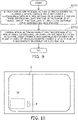
- FIGS. 8 and 9 are schematic flow charts showing a main operation example of the monitoring system 1 according to the first embodiment.
- FIG. 8 is a schematic flow chart showing a specification process of camera positional attitude information of the surveillance cameras X and Y, the vehicle-mounted camera Z of the automobile B, and the like shown in FIG. 1
- FIG. 9 is a schematic flow chart showing a process of displaying a warning of the presence of the automobile W and the pedestrian P shown in FIG. 1 on a display that is a display portion of the automobile B.
- FIGS. 8 and 9 will be described using an example in which a warning of the presence of the automobile W and the pedestrian P is displayed mainly using the surveillance cameras X and Y shown in FIG. 1 , and the survey apparatuses T and U will be described later.
- step (hereinafter, referred to as "ST") 1 shown in FIG. 8 when the surveillance camera X and the surveillance camera Y arranged at the intersection A enter within 50 m of the automobile B being mounted with the vehicle-mounted camera Z shown in FIG. 1 and traveling on a road while imaging with the vehicle-mounted camera Z, the "camera Z-side communication apparatus 102" shown in FIG. 5 or, more specifically, Bluetooth detects that the surveillance camera X and the surveillance camera Y have entered within 50 m of the automobile B, constructs a "network" with the surveillance cameras X and Y, and creates a state where the three cameras Z, X, and Y can communicate with each other.
- GPS Global Positioning System
- the Internet or the like may be used instead.
- positional information and attitude information of the three cameras are generated.
- a "feature point processing portion (program) 111" shown in FIG. 6 of the vehicle-mounted camera Z operates to create information on a feature point on images from image information of the vehicle-mounted camera Z, the surveillance camera X, and the surveillance camera Y and store the created feature point information in a "feature point information storage portion 112" in FIG. 6 .
- the processing portion 111 operates and refers to the "feature point information storage portion 112", specifies a common feature point on images of the vehicle-mounted camera Z, the surveillance camera X, and the surveillance camera Y, and causes a "common feature portion storage portion 113" to store the specified common feature point.
- a "matching processing portion (program) 114" shown in FIG. 6 operates and refers to the "common feature portion storage portion 113", retrieves a "common feature point” among the vehicle-mounted camera Z, the surveillance camera X, and the surveillance camera Y and performs matching processing, and stores a result of the matching processing in a "matching information storage portion 115" shown.
- a "relative positional attitude information generating portion (program) 116" shown in FIG. 6 operates and, based on information in the "matching information storage portion 115", obtains a relative positional attitude among the vehicle-mounted camera Z, the surveillance camera X, and the surveillance camera Y, and stores the obtained relative positional attitude in a "relative positional attitude information storage portion 121" shown in FIG. 7 .
- each camera (each of the vehicle-mounted camera Z, the surveillance camera X, and the surveillance camera Y) is specified.
- FIG. 9 is a schematic flow chart showing a process of displaying a warning of the presence of the automobile W and the pedestrian P shown in FIG. 1 on a display that is a display portion of the automobile B as described above.
- the "three-dimensional information acquiring portion (program) 122" shown in FIG. 7 operates and, by causing SfM processing that is a photogrammetric technique to be performed among the vehicle-mounted camera Z, the surveillance camera X, and the surveillance camera Y, three-dimensional information of the "automobile W", the "pedestrian P", and the "building V” are obtained and stored in the "three-dimensional information storage portion 123" shown in FIG. 7 .
- the "building V" is restored by the vehicle-mounted camera Z, the surveillance camera X, and the surveillance camera Y and the "pedestrian P" and the “automobile W” are restored by the surveillance camera X and the surveillance camera Y.
- FIG. 10 is a schematic view showing an example in which the automobile W and the pedestrian P shown in FIG. 1 are displayed on the display of the automobile B.
- the display displays an image from the point of view of the vehicle-mounted camera Z of the automobile B and, at the same time, the "pedestrian P" and the “automobile W” which are positioned in a blind spot hidden behind the building V are indicated by dashed lines.
- a driver of the automobile B and the like can readily ascertain and beware of the "pedestrian P" and the like in the blind spot portion by simply viewing the display and viewing a single screen.
- the driver and the like can promptly and accurately ascertain a risk or the like.
- the display portion has been described in the present embodiment as a display provided in the automobile B as shown in FIG. 10
- the present invention is not limited thereto and the display portion may be a "rearview mirror" shown in FIG. 11(a) or a “side mirror” shown in FIG. 11(b) or, alternatively, a mode in which display is performed on a windshield or the like may be adopted.
- the automobile W and the pedestrian P may be displayed together with map information on a display used by a car navigation system.
- FIGS. 11(a) and 11(b) are schematic views showing a modification of the display portion.
- the survey apparatuses T and U are arranged at the intersection A shown in FIG. 1 and the survey apparatuses T and U are configured as shown in FIGS. 3 and 4 , the survey apparatuses T and U may be used independently or in combination with the surveillance cameras X and Y.
- the survey apparatuses T and U shown in FIG. 1 and the like acquire accurate three-dimensional information (point group information or the like) of the automobile W and the pedestrian P by irradiating the automobile W and the pedestrian P with ranging light and receiving reflected light.
- the driver of the automobile B is capable of viewing information with higher accuracy.
- the automobile B shown in FIG. 1 is an emergency vehicle configured to notify automobiles present within 50 m of its own approach and to display the automobile W and the pedestrian P in a blind spot portion on a display of the emergency vehicle.
- a configuration is adopted in which a network is constructed with a vehicle-mounted camera of an automobile capable of communicating using Bluetooth within a 50 m-radius of a vehicle-mounted camera of the emergency vehicle and an approach by the emergency vehicle is notified.
- the emergency vehicle can notify another automobile that the emergency vehicle is approaching the other vehicle and, at the same time, since the emergency vehicle can also ascertain a blind spot portion of the emergency vehicle, the emergency vehicle can travel more safely.
- the present embodiment represents an example in which a construction vehicle E and heavy machinery F are present at a construction/building site D and an automobile G is being driven on the site D.
- vehicle-mounted cameras H, I, and J are respectively installed on the automobile G, the construction vehicle E, and the heavy machinery F.
- a "network" is constructed among the three vehicle-mounted cameras H, I, and J, and the three vehicle-mounted cameras H, I, and J communicate with each other.
- the "worker K” is restored by the vehicle-mounted cameras I and J of the construction vehicle E and the heavy machinery F and the "fill L” is restored by the vehicle-mounted cameras H, I, and J of the automobile G, the construction vehicle E, and the heavy machinery F.
- an image of the "worker K" of which three-dimensional information has been restored by the vehicle-mounted cameras I and J of the construction vehicle E and the heavy machinery F can be changed to a point of view of the vehicle-mounted camera H of the automobile G and displayed on the display of the automobile G.
- the point of view of the vehicle-mounted camera H of the automobile G and the "worker K" in a blind spot of the "fill L” can be ascertained and a state thereof can be displayed.
- FIG. 12 is a schematic view showing a screen example of the display of the automobile G.
- the display can alert a driver of the automobile G or the like to the worker K.
- the display that is a display portion is not limited to the display shown in FIG. 12 and may be a windshield, a side mirror, a rearview mirror, or the like in a similar manner to the first embodiment.
- the information may be displayed together with a map or the like in a car navigation system.
- a configuration may be adopted in which, when distances between the automobile G and the construction vehicle E and the heavy machinery F are calculated and the distances are too short, a warning is output to the automobile G and, further, the construction vehicle E and the heavy machinery F are controlled and stopped.
- a program to be executed by a computer may be distributed while being stored in storage media such as a magnetic disk (a floppy (registered trademark) disk, a hard disk, or the like), an optical disk (a CD-ROM, a DVD, or the like), a magneto optical disk (MO), and a semiconductor memory.
- storage media such as a magnetic disk (a floppy (registered trademark) disk, a hard disk, or the like), an optical disk (a CD-ROM, a DVD, or the like), a magneto optical disk (MO), and a semiconductor memory.
- the storage media may be any storage media that are capable of storing a program and readable by a computer.
- a storage format of the storage media is not particularly limited.
- an OS operating system
- MW middleware
- database management software and network software may execute a part of processing steps for realizing the present embodiment.
- the storage media in the present invention are not limited to media that are independent of a computer and include storage media to which a program transmitted through a LAN, the Internet, or the like has been downloaded and which store or temporarily store the downloaded program.
- the computer in the present invention need only execute respective processing steps in the present embodiment based on a program stored in a storage medium and may be an apparatus constituted by a single personal computer (PC) or the like or may be a system or the like in which a plurality of apparatuses are connected via a network.
- PC personal computer
- the computer in the present invention is not limited to a personal computer and collectively refers to devices and apparatuses capable of realizing functions of the present invention including arithmetic processing units and microcomputers included in information processing devices.
Landscapes
- Engineering & Computer Science (AREA)
- Physics & Mathematics (AREA)
- General Physics & Mathematics (AREA)
- Remote Sensing (AREA)
- Radar, Positioning & Navigation (AREA)
- Multimedia (AREA)
- Theoretical Computer Science (AREA)
- Computer Vision & Pattern Recognition (AREA)
- Life Sciences & Earth Sciences (AREA)
- Automation & Control Theory (AREA)
- Atmospheric Sciences (AREA)
- Electromagnetism (AREA)
- Computer Networks & Wireless Communication (AREA)
- Signal Processing (AREA)
- Analytical Chemistry (AREA)
- Chemical & Material Sciences (AREA)
- Computing Systems (AREA)
- Artificial Intelligence (AREA)
- Databases & Information Systems (AREA)
- Health & Medical Sciences (AREA)
- Evolutionary Computation (AREA)
- Software Systems (AREA)
- General Health & Medical Sciences (AREA)
- Medical Informatics (AREA)
- Mechanical Engineering (AREA)
- Traffic Control Systems (AREA)
- Closed-Circuit Television Systems (AREA)
Abstract
Description
- The present invention relates to an information display system that displays information for an operator or the like who drives and operates an automobile or the like, a control method of the information display system, and a control program of the information display system.
- Conventionally, proposals have been made for displaying, when an operator operates an apparatus such as a work machine, the situation of operator's surroundings on a display visible to the operator (for example, PTL 1).
- [PTL 1]
WO 2017/191853 - However, in such proposals, when displaying information on the surroundings, such as information on blind spot of the operator, on the display, shapes viewed from various angles that differ from a point of view of the operator are displayed as reference information.
- Therefore, there has been a problem in that it is difficult for the operator to promptly ascertain the situation of surroundings or the like.
- In addition, there has also been a problem in that, when displaying external information or the like, imaged by a camera, on the display in order to have the operator ascertain the external information, an image taken by the camera does not enable the operator to ascertain information on a portion that constitutes a blind spot of the operator from among structures and the like, i.e., external information.
- In consideration thereof, an object of the present invention is to provide an information display system capable of showing to an object person viewing a display portion, such as a display, an object displayed on the display portion from a point of view of the operator in an accurate manner, a control method of the information display system, and a control program of the information display system.
- According to the present invention, the object described above can be achieved by an information display system including: a plurality of imaging apparatuses that image an object from a point of view that differs from a point of view of a user; and a display portion that displays the object from the point of view of the user, wherein the information display system generates three-dimensional information of the object on the basis of imaging information obtained by imaging the object by the plurality of imaging apparatuses and displays, on the basis of the three-dimensional information, the object on the display portion from the point of view of the user.
- According to the configuration described above, three-dimensional information of an object is generated on the basis of imaging information obtained by imaging the object by the plurality of imaging apparatuses, and the object can be displayed on the display portion from the point of view of a user on the basis of the three-dimensional information.
- Accordingly, the object can be displayed on the display portion from the point of view of the user and in an accurate manner.
- Preferably, the three-dimensional information of the object is generated using a photogrammetric technique.
- According to the configuration described above, since three-dimensional information is generated using a method of a photogrammetric technique such as SfM (Structure from Motion), the three-dimensional information of the object can be generated in an accurate manner.
- Preferably, the object is present in a blind spot portion from the point of view of the user.
- According to the configuration described above, even when the object is present in a blind spot portion from the point of view of the user, the object can be accurately displayed as three-dimensional information.
- Preferably, the information display system includes a survey apparatus that performs a three-dimensional survey by irradiating the object with ranging light and receiving reflected ranging light from the object.
- According to the configuration described above, three-dimensional shape information of the object can be accurately measured by a survey performed by a survey apparatus.
- Therefore, by displaying three-dimensional information (point group information or the like) obtained by a survey together with three-dimensional information based on imaging information on the display portion, information with higher accuracy can be displayed.
- According to the present invention, the object described above can be achieved by a control method of an information display system including: a plurality of imaging apparatuses that image an object from a point of view that differs from a point of view of a user; and a display portion that displays the object from the point of view of the user, the control method including generating three-dimensional information of the object on the basis of imaging information obtained by imaging the object by the plurality of imaging apparatuses and displaying, on the basis of the three-dimensional information, the object on the display portion from the point of view of the user.
- According to the present invention, the object described above can be achieved by a control program of a monitoring system that causes an information display system including: a plurality of imaging apparatuses that image an object from a point of view that differs from a point of view of a user; and a display portion that displays the object from the point of view of the user, to execute: a function of generating three-dimensional information of the object on the basis of imaging information obtained by imaging the object by the plurality of imaging apparatuses; and a function of displaying, on the basis of the three-dimensional information, the object on the display portion from the point of view of the user.
- The present invention can advantageously provide an information display system capable of showing to an object person viewing a display portion, such as a display, an object displayed on the display portion from a point of view of the operator in an accurate manner, a control method of the information display system, and a control program of the information display system.
-
-
FIG. 1 is a schematic view showing a "monitoring system 1" that is an embodiment of the information display system according to the present invention; -
FIG. 2 is a schematic view showing main components of an "imaging unit 27" mounted to surveillance cameras X and Y shown inFIG. 1 ; -
FIG. 3 is a schematic perspective view showing a survey apparatus T and the like shown inFIG. 1 ; -
FIG. 4 is a schematic view showing a main internal structure of anenclosure 7 of survey apparatuses T and U shown inFIG. 3 ; -
FIG. 5 is a schematic block diagram showing main components of a vehicle-mounted camera Z shown inFIG. 1 ; -
FIG. 6 is a schematic block diagram showing main components of a camera Z-side first variousinformation storage portion 110; -
FIG. 7 is a schematic block diagram showing main components of a camera Z-side second variousinformation storage portion 120; -
FIG. 8 is a main flow chart showing a specification process of camera positional attitude information of the surveillance cameras X and Y, the vehicle-mounted camera Z of an automobile B, and the like shown inFIG. 1 ; -
FIG. 9 is a schematic flow chart showing a process of displaying a warning of the presence of an automobile W and a pedestrian P shown inFIG. 1 on a display that is a display portion of the automobile B; -
FIG. 10 is a schematic view showing an example in which the automobile W and the pedestrian P inFIG. 1 are displayed on the display of the automobile B; -
FIGS. 11(a) and 11(b) are schematic views showing a modification of the display portion; and -
FIG. 12 is a schematic view showing a screen example of a display of an automobile G. - Hereinafter, a preferred embodiment of the present invention will be described in detail with reference to accompanying drawings and the like.
- Although the embodiment described below is a preferred specific example of the present invention and is therefore subjected to various favorable technical limitations, it is to be understood that the scope of the present invention is by no means limited by the described aspects unless specifically noted otherwise hereinafter.
-
FIG. 1 is a schematic view showing a "monitoring system 1" that is an embodiment of the information display system according to the present invention. - As shown in
FIG. 1 , in thepresent system 1, for example, a surveillance camera X and a surveillance camera Y which are imaging apparatuses are installed at, for example, an intersection A. - In addition, a survey apparatus T and a survey apparatus U are also installed at the intersection A.
- An automobile B is approaching the intersection A described above and, for example, a vehicle-mounted camera Z that is an imaging apparatus is installed in the automobile B and configured so as to capture an image from a point of view of a driver's seat of a user of the automobile B.
- On the other hand, a building V that is visible from the user of the automobile B is arranged at the intersection A and, at the same time, for example, an automobile W and a pedestrian P which are objects are positioned in a blind spot portion of the user of the automobile B created by the building V, the automobile W and the pedestrian P being positioned so as to be visible from the surveillance cameras X and Y and surveyable from the survey apparatuses T and U.
-
Imaging Unit 27 of Surveillance Camera X etc.FIG. 2 is a schematic view showing main components of an "imaging unit 27" mounted to the surveillance cameras X and Y shown inFIG. 1 . - As shown in
FIG. 2 , theimaging unit 27 has an imagingoptical axis 5. The imagingoptical axis 5 is configured such that an orientation thereof can be changed and, for example, images of the automobile W and the pedestrian P can be acquired by pointing the imagingoptical axis 5 toward the automobile W and the pedestrian P. - In addition, an
imaging lens 48 and animaging element 49 are provided on the imagingoptical axis 5. Theimaging element 49 is a CCD or a CMOS sensor which is an aggregate of pixels, and a position of each pixel on an image element can be specified. - For example, a position of each pixel is specified in a coordinate system of which an origin is the optical axis of the
imaging unit 27. - Main Components of Survey Apparatus T etc.
FIG. 3 is a schematic perspective view showing the survey apparatus T and the like shown inFIG. 1 . - As shown in
FIG. 3 , the survey apparatuses T and U are provided via abase unit 3 on atripod 2 installed at an installation reference point R and are configured to be capable of three-dimensional measurement (survey) of, for example, the "automobile W" and the "pedestrian P" which are measurement objects. - The
base unit 3 of the survey apparatus T and the like has aprotractor plate 8 which rotates in a horizontal direction and which is capable of detecting a rotational angle and avertical rotation portion 9 which is capable of rotating in a vertical direction and which can be fixed at a predetermined angle and, consequently, the survey apparatuses T and U are configured to be directly attached to thevertical rotation portion 9. - Therefore, the survey apparatuses T and U are also configured so as to rotate in the vertical direction around a machine reference point and rotate in the horizontal direction around the machine reference point.
-
FIG. 4 is a schematic view showing a main internal structure of anenclosure 7 of the survey apparatuses T and U shown inFIG. 3 . - A survey apparatus-
side display portion 11 and anoperating portion 12 are provided on a rear surface of theenclosure 7 and ameasurement unit 20 having a ranging optical axis 4, acalculation processing unit 24, an emissiondirection detecting portion 25 that detects an emission direction of ranging light, anattitude detecting unit 26 that detects an inclination of the survey apparatus 10 in the horizontal direction, an opticalaxis deflecting unit 36 that detects the ranging optical axis 4, and the like are provided inside theenclosure 7. - In addition, the
measurement unit 20, theattitude detecting unit 26, and the opticalaxis deflecting unit 36 are integrally arranged. - The
measurement unit 20 has a ranginglight emitting portion 21, a light-receivingportion 22, and a rangingportion 23, the ranginglight emitting portion 21 emits ranging light and has an emissionoptical axis 31, a light-emitting element 32 (such as a laser diode (LD)) is provided on the emissionoptical axis 31, and aprojection lens 33 is further provided on the emissionoptical axis 31. - In addition, a first
reflecting mirror 34 as a deflecting optical member is provided on the emissionoptical axis 31, and a second reflectingmirror 35 as a deflecting optical member is arranged on a receptionoptical axis 37 so as to face the first reflectingmirror 34. - Due to the first reflecting
mirror 34 and the second reflectingmirror 35, the emissionoptical axis 31 is configured so as to become congruent with the ranging optical axis 4. - In addition, the optical
axis deflecting unit 36 is arranged on the ranging optical axis 4. - While the light-receiving
portion 22 receives reflected ranging light from the automobile W and the pedestrian P which are measurement objects, the light-receivingportion 22 has a receptionoptical axis 37 that is parallel to the emissionoptical axis 31 and the receptionoptical axis 37 is common to the ranging optical axis 4. - A light-receiving
element 38 such as a photodiode (PD) is provided on the receptionoptical axis 37 and animaging lens 39 is also arranged on the receptionoptical axis 37. - The
imaging lens 39 focuses the reflected ranging light on the light-receivingelement 38, and the light-receivingelement 38 receives the reflected ranging light and generates a light reception signal. The light reception signal is input to the rangingportion 23. - The optical
axis deflecting unit 36 is arranged on an object side of theimaging lens 39 on the receptionoptical axis 37 shown inFIG. 4 . - The ranging
portion 23 controls the light-emittingelement 32 and causes the light-emittingelement 32 to emit a laser beam as the ranging light. - The ranging optical axis 4 is configured to be deflected by the optical axis deflecting unit 36 (a ranging
light deflecting portion 36a) so as to direct the laser beam toward a ranging point (the automobile W and the pedestrian P). - Specifically, the laser beam is emitted toward the automobile W and the pedestrian P, the reflected ranging light having been reflected by the automobile W and the pedestrian P which are measurement objects enters the light-receiving
portion 22 via the optical axis deflecting unit 36 (a reflected ranginglight deflecting portion 36b) and theimaging lens 39. - The reflected ranging
light deflecting portion 36b re-deflects the ranging optical axis 4 having been deflected by the ranginglight deflecting portion 36a so that the ranging optical axis 4 returns to its original state and causes the light-receivingelement 38 to receive the reflected ranging light. - The light-receiving
element 38 sends a light reception signal to the rangingportion 23 and the rangingportion 23 performs ranging of the measurement point (the automobile W and the pedestrian P) on the basis of the light reception signal from the light-receivingelement 38. - As shown in
FIG. 4 , a pair ofoptical prisms axis deflecting unit 36. - Fresnel prisms that are used as the
optical prisms prism elements prism elements - Trajectory Control of Laser Using Optical
Axis Deflecting Unit 36 - Ranging light is emitted from the light-emitting
element 32, the ranging light is made into a parallel luminous flux by theprojection lens 33, passes through the ranginglight deflecting portion 36a (theprism elements - By passing through the ranging
light deflecting portion 36a, the ranging light is deflected and output in a direction of the automobile W and the pedestrian P that is a necessary direction by theprism elements - In addition, the reflected ranging light having been reflected by the automobile W and the pedestrian P passes through and is incident to the reflected ranging
light deflecting portion 36b (theprism elements element 38 by theimaging lens 39. - Subsequently, due to the reflected ranging light passing through the reflected ranging
light deflecting portion 36b, an optical axis of the reflected ranging light is deflected by theprism elements optical axis 37. - In other words, a configuration is adopted in which, due to a combination of rotational positions of the
prism element 42a and theprism element 42b, a deflection direction and a deflection angle of the ranging light to be emitted can be arbitrarily changed. - While the survey apparatus according to the present embodiment does not have a camera, a configuration may be adopted in which the imaging apparatus has a camera function.
- The surveillance cameras X and Y, the survey apparatuses T and U, and the vehicle-mounted camera Z of the automobile B shown in
FIG. 1 have computers, and the computers include a CPU (Central Processing Unit), a RAM (Random Access Memory), a ROM (Read Only Memory), and the like (not illustrated) which are connected via a bus or the like. -
FIG. 5 is a schematic block diagram showing main components of the vehicle-mounted camera Z shown inFIG. 1 . - As shown in
FIG. 5 , the vehicle-mounted camera Z has a "camera Z-side control portion 101", and in addition to controlling the "camera Z-side communication apparatus" that communicates with the surveillance camera X and the like shown inFIG. 1 and the "camera Z-side imaging unit 103" that images an object, thecontrol portion 101 also controls a "camera Z-side first variousinformation storage portion 110" and a "camera Z-side second variousinformation storage portion 120". -
FIGS. 6 to 7 are, respectively, schematic block diagrams showing main components of the "camera Z-side first variousinformation storage portion 110 and the "camera Z-side second variousinformation storage portion 120". Contents of these components will be described later. - It should be noted that the "surveillance camera X", the "surveillance camera Y", the "vehicle-mounted camera Z", and the like shown in
FIG. 1 are configured so that times of day can be synchronized with each other and acquisition of data can be executed at a designated time of day. - In addition, the respective cameras X, Y, and Z are also configured so as to be capable of acquiring an accurate time of day of photography using an GNSS (Global Navigation Satellite System) such as GPS (Global Positioning System) and accessing an NTP (Network Time protocol) server via an Internet network or the like (not illustrated) to acquire an accurate time of day.
- In this case, an NTP server refers to a server that acquires and distributes accurate time of day information.
-
FIGS. 8 and9 are schematic flow charts showing a main operation example of themonitoring system 1 according to the first embodiment. - Specifically,
FIG. 8 is a schematic flow chart showing a specification process of camera positional attitude information of the surveillance cameras X and Y, the vehicle-mounted camera Z of the automobile B, and the like shown inFIG. 1 , andFIG. 9 is a schematic flow chart showing a process of displaying a warning of the presence of the automobile W and the pedestrian P shown inFIG. 1 on a display that is a display portion of the automobile B. - In addition, the operation example shown in
FIGS. 8 and9 will be described using an example in which a warning of the presence of the automobile W and the pedestrian P is displayed mainly using the surveillance cameras X and Y shown inFIG. 1 , and the survey apparatuses T and U will be described later. - First, a "specification process of camera positional attitude information of the surveillance cameras X and Y, the vehicle-mounted camera Z of an automobile B, and the like" will be described with reference to
FIG. 8 . - In step (hereinafter, referred to as "ST") 1 shown in
FIG. 8 , when the surveillance camera X and the surveillance camera Y arranged at the intersection A enter within 50 m of the automobile B being mounted with the vehicle-mounted camera Z shown inFIG. 1 and traveling on a road while imaging with the vehicle-mounted camera Z, the "camera Z-side communication apparatus 102" shown inFIG. 5 or, more specifically, Bluetooth detects that the surveillance camera X and the surveillance camera Y have entered within 50 m of the automobile B, constructs a "network" with the surveillance cameras X and Y, and creates a state where the three cameras Z, X, and Y can communicate with each other. - While a description using Bluetooth has been given in the present embodiment, the present invention is not limited thereto and GPS (Global Positioning System), the Internet, or the like may be used instead.
- Next, in processes subsequent to ST2, positional information and attitude information of the three cameras (the surveillance camera X, the surveillance camera Y, and the vehicle-mounted camera Z) are generated.
- While the processes are respectively executed by the three cameras, hereinafter, the vehicle-mounted camera Z will be described as an example.
- First, in ST2, a "feature point processing portion (program) 111" shown in
FIG. 6 of the vehicle-mounted camera Z operates to create information on a feature point on images from image information of the vehicle-mounted camera Z, the surveillance camera X, and the surveillance camera Y and store the created feature point information in a "feature pointinformation storage portion 112" inFIG. 6 . - The process then proceeds to ST3. In ST3, the
processing portion 111 operates and refers to the "feature pointinformation storage portion 112", specifies a common feature point on images of the vehicle-mounted camera Z, the surveillance camera X, and the surveillance camera Y, and causes a "common featureportion storage portion 113" to store the specified common feature point. - The process then proceeds to ST4. In ST4, a "matching processing portion (program) 114" shown in
FIG. 6 operates and refers to the "common featureportion storage portion 113", retrieves a "common feature point" among the vehicle-mounted camera Z, the surveillance camera X, and the surveillance camera Y and performs matching processing, and stores a result of the matching processing in a "matchinginformation storage portion 115" shown. - Next, a "relative positional attitude information generating portion (program) 116" shown in
FIG. 6 operates and, based on information in the "matchinginformation storage portion 115", obtains a relative positional attitude among the vehicle-mounted camera Z, the surveillance camera X, and the surveillance camera Y, and stores the obtained relative positional attitude in a "relative positional attitudeinformation storage portion 121" shown inFIG. 7 . - As a result, a camera positional attitude of each camera (each of the vehicle-mounted camera Z, the surveillance camera X, and the surveillance camera Y) is specified.
- Next, a process of detecting the "automobile W" and the "pedestrian P" which correspond to a blind spot portion of the building V shown in
FIG. 1 from the vehicle-mounted camera Z of the automobile B, displaying the detected "automobile W" and "pedestrian P" on a display portion (display) or the like of the automobile B, and issuing a warning or the like will be described with reference toFIG. 9 . -
FIG. 9 is a schematic flow chart showing a process of displaying a warning of the presence of the automobile W and the pedestrian P shown inFIG. 1 on a display that is a display portion of the automobile B as described above. - First, in ST11 in
FIG. 9 , the "three-dimensional information acquiring portion (program) 122" shown inFIG. 7 operates and, by causing SfM processing that is a photogrammetric technique to be performed among the vehicle-mounted camera Z, the surveillance camera X, and the surveillance camera Y, three-dimensional information of the "automobile W", the "pedestrian P", and the "building V" are obtained and stored in the "three-dimensionalinformation storage portion 123" shown inFIG. 7 . - Specifically, using a method such as SfM (Structure from Motion) that is a photogrammetric technique, three-dimensional information of the "building V", the "pedestrian P", and the "automobile W" which appear in a supplied image is restored, and the restoration information is shared by each camera.
- Specifically, the "building V" is restored by the vehicle-mounted camera Z, the surveillance camera X, and the surveillance camera Y and the "pedestrian P" and the "automobile W" are restored by the surveillance camera X and the surveillance camera Y.
- The process then proceeds to ST12. In ST12, an image of the "pedestrian P" and the "automobile W" of which three-dimensional information has been restored by the surveillance camera X and the surveillance camera Y is changed to a point of view of the vehicle-mounted camera Z of the automobile B and displayed on the display of the automobile B.
- Since positional information and attitude information of each camera (each of the vehicle-mounted camera Z, the surveillance camera X, and the surveillance camera Y) have been acquired as described above by the process shown in
FIG. 8 , an image taken by another camera (the surveillance cameras X and Y) can be converted into the point of view of the vehicle-mounted camera Z. -
FIG. 10 is a schematic view showing an example in which the automobile W and the pedestrian P shown inFIG. 1 are displayed on the display of the automobile B. - As shown in
FIG. 10 , the display displays an image from the point of view of the vehicle-mounted camera Z of the automobile B and, at the same time, the "pedestrian P" and the "automobile W" which are positioned in a blind spot hidden behind the building V are indicated by dashed lines. - Therefore, a driver of the automobile B and the like can readily ascertain and beware of the "pedestrian P" and the like in the blind spot portion by simply viewing the display and viewing a single screen.
- In other words, since the blind spot portion is not displayed in a window or the like showing a different image from a different point of view as is conventional, the driver and the like can promptly and accurately ascertain a risk or the like.
- While the display portion has been described in the present embodiment as a display provided in the automobile B as shown in
FIG. 10 , the present invention is not limited thereto and the display portion may be a "rearview mirror" shown inFIG. 11(a) or a "side mirror" shown inFIG. 11(b) or, alternatively, a mode in which display is performed on a windshield or the like may be adopted. - Furthermore, the automobile W and the pedestrian P may be displayed together with map information on a display used by a car navigation system.
-
FIGS. 11(a) and 11(b) are schematic views showing a modification of the display portion. - Since the survey apparatuses T and U are arranged at the intersection A shown in
FIG. 1 and the survey apparatuses T and U are configured as shown inFIGS. 3 and 4 , the survey apparatuses T and U may be used independently or in combination with the surveillance cameras X and Y. - In this case, when the automobile B approaches the intersection A and the automobile B comes within 50 m of the survey apparatus T and the survey apparatus U, a "network" is constructed and communication can be performed in a similar manner to the surveillance camera X and the like described earlier.
- Next, the survey apparatuses T and U shown in
FIG. 1 and the like acquire accurate three-dimensional information (point group information or the like) of the automobile W and the pedestrian P by irradiating the automobile W and the pedestrian P with ranging light and receiving reflected light. - In addition, by converting the accurate three-dimensional point group information or the like acquired by the survey apparatus T and the like into the point of view of the vehicle-mounted camera Z and displaying the converted information on the display of the automobile B or the like, the driver of the automobile B is capable of viewing information with higher accuracy.
- Since many components of the present embodiment are similar to those of the first embodiment described above, the following description will focus on differences instead.
- In the present embodiment, the automobile B shown in
FIG. 1 is an emergency vehicle configured to notify automobiles present within 50 m of its own approach and to display the automobile W and the pedestrian P in a blind spot portion on a display of the emergency vehicle. - Specifically, a configuration is adopted in which a network is constructed with a vehicle-mounted camera of an automobile capable of communicating using Bluetooth within a 50 m-radius of a vehicle-mounted camera of the emergency vehicle and an approach by the emergency vehicle is notified.
- Accordingly, since the emergency vehicle can notify another automobile that the emergency vehicle is approaching the other vehicle and, at the same time, since the emergency vehicle can also ascertain a blind spot portion of the emergency vehicle, the emergency vehicle can travel more safely.
- Since many components of the present embodiment are similar to those of the first embodiment described above, the following description will focus on differences instead.
- The present embodiment represents an example in which a construction vehicle E and heavy machinery F are present at a construction/building site D and an automobile G is being driven on the site D.
- In this case, vehicle-mounted cameras H, I, and J are respectively installed on the automobile G, the construction vehicle E, and the heavy machinery F.
- In the present embodiment, when the automobile G is traveling and the vehicle-mounted camera I of the construction vehicle E and the vehicle-mounted camera J of the heavy machinery F approach the automobile G within a radius of 50 m, the approach is detected by Bluetooth in a similar manner to the first embodiment, a "network" is constructed among the three vehicle-mounted cameras H, I, and J, and the three vehicle-mounted cameras H, I, and J communicate with each other.
- Next, in a similar manner to the first embodiment, relative positional attitude information of the three vehicle-mounted cameras H, I, and J is specified.
- Accordingly, a camera positional attitude of each of the vehicle-mounted cameras H, I, and J is specified.
- Next, in a similar manner to the first embodiment, an object in a blind spot portion is detected.
- Specifically, a configuration is adopted in which, while a "fill L" that is visible from the vehicle-mounted camera H of the automobile G and a "worker K" present in a blind spot portion hidden by the "fill L" are detected, three-dimensional information is obtained by SfM (Structure from Motion) processing that is a photogrammetric technique among the three vehicle-mounted cameras H, I, and J in a similar manner to the first embodiment.
- In other words, using a method such as SfM, three-dimensional information of the "worker K" and the "fill L" which appear in a supplied image is restored, and the restoration information is shared by each of the cameras H, I, and J.
- Specifically, the "worker K" is restored by the vehicle-mounted cameras I and J of the construction vehicle E and the heavy machinery F and the "fill L" is restored by the vehicle-mounted cameras H, I, and J of the automobile G, the construction vehicle E, and the heavy machinery F.
- In addition, an image of the "worker K" of which three-dimensional information has been restored by the vehicle-mounted cameras I and J of the construction vehicle E and the heavy machinery F can be changed to a point of view of the vehicle-mounted camera H of the automobile G and displayed on the display of the automobile G.
- Accordingly, the point of view of the vehicle-mounted camera H of the automobile G and the "worker K" in a blind spot of the "fill L" can be ascertained and a state thereof can be displayed.
-
FIG. 12 is a schematic view showing a screen example of the display of the automobile G. - As shown in
FIG. 12 , by displaying the fill L and indicating the worker K in a blind spot hidden by the fill L by a dashed line or the like, the display can alert a driver of the automobile G or the like to the worker K. - Even in the present embodiment, the display that is a display portion is not limited to the display shown in
FIG. 12 and may be a windshield, a side mirror, a rearview mirror, or the like in a similar manner to the first embodiment. In addition, the information may be displayed together with a map or the like in a car navigation system. - Furthermore, a configuration may be adopted in which, when distances between the automobile G and the construction vehicle E and the heavy machinery F are calculated and the distances are too short, a warning is output to the automobile G and, further, the construction vehicle E and the heavy machinery F are controlled and stopped.
- While the present embodiment has been described above using an example in which the present invention is realized as an apparatus, the present invention is not limited thereto and a program to be executed by a computer may be distributed while being stored in storage media such as a magnetic disk (a floppy (registered trademark) disk, a hard disk, or the like), an optical disk (a CD-ROM, a DVD, or the like), a magneto optical disk (MO), and a semiconductor memory.
- In addition, the storage media may be any storage media that are capable of storing a program and readable by a computer. A storage format of the storage media is not particularly limited.
- Furthermore, an OS (operating system) running on a computer based on instructions of a program having been installed to the computer from a storage medium, MW (middleware) such as database management software and network software, and the like may execute a part of processing steps for realizing the present embodiment.
- Moreover, the storage media in the present invention are not limited to media that are independent of a computer and include storage media to which a program transmitted through a LAN, the Internet, or the like has been downloaded and which store or temporarily store the downloaded program.
- In addition, the computer in the present invention need only execute respective processing steps in the present embodiment based on a program stored in a storage medium and may be an apparatus constituted by a single personal computer (PC) or the like or may be a system or the like in which a plurality of apparatuses are connected via a network.
- Furthermore, the computer in the present invention is not limited to a personal computer and collectively refers to devices and apparatuses capable of realizing functions of the present invention including arithmetic processing units and microcomputers included in information processing devices.
- An embodiment of the present invention has been described above. However, it is to be understood that the present invention is not limited to the embodiment described above and that various modifications can be made without departing from the scope of the appended claims.
-
- 1
- monitoring system
- 2
- tripod
- 3
- base unit
- 5
- imaging optical axis
- 7
- enclosure
- 8
- protractor plate
- 9
- vertical rotation portion
- 10
- survey apparatus
- 11
- survey apparatus-side display portion
- 12
- operating portion
- 20
- measurement unit
- 21
- ranging light emitting portion
- 22
- light-receiving portion
- 23
- ranging portion
- 24
- calculation processing unit
- 25
- emission direction detecting portion
- 26
- attitude detecting unit
- 27
- imaging unit
- 31
- emission optical axis
- 32
- light-emitting element
- 33
- projection lens
- 34
- first reflecting mirror
- 35
- second reflecting mirror
- 36
- optical axis deflecting unit
- 36a
- ranging light deflecting portion
- 36b
- reflected ranging light deflecting portion
- 37
- reception optical axis
- 38
- light-receiving element
- 39
- imaging lens
-
41a 41b - optical prisms
-
42a 42b - prism elements
-
43a 43b - prism elements
- 48
- imaging lens
- 49
- imaging element
- 101
- camera Z-side control portion
- 102
- camera Z-side communication apparatus
- 103
- camera Z-side imaging unit
- 110
- camera Z-side first various information storage portion
- 111
- feature point processing portion
- 112
- feature point information storage portion
- 113
- common feature portion storage portion
- 114
- matching processing portion
- 115
- matching information storage portion
- 116
- relative positional attitude information generating portion
- 120
- camera Z-side second various information storage portion
- 121
- relative positional attitude information storage portion
- 122
- three-dimensional information acquiring portion
- 123
- three-dimensional information storage portion
- A
- intersection
- B, W
- automobile
- K
- worker
- L
- fill
- P
- pedestrian
- T, U
- survey apparatuses
- V
- building
- X, Y
- surveillance cameras
Claims (6)
- An information display system comprising:a plurality of imaging apparatuses that image an object from a point of view that differs from a point of view of a user; anda display portion that displays the object from the point of view of the user, whereinthe information display system generates three-dimensional information of the object on the basis of imaging information obtained by imaging the object by the plurality of imaging apparatuses and displays, on the basis of the three-dimensional information, the object on the display portion from the point of view of the user.
- The information display system according to claim 1, wherein the three-dimensional information of the object is generated using a photogrammetric technique.
- The information display system according to claim 1 or 2, wherein the object is present in a blind spot portion from the point of view of the user.
- The information display system according to any one of claims 1 to 3, comprising a survey apparatus that performs a three-dimensional survey by irradiating the object with ranging light and receiving reflected ranging light from the object.
- A control method of an information display system including:a plurality of imaging apparatuses that image an object from a point of view that differs from a point of view of a user; anda display portion that displays the object from the point of view of the user, the control method comprisinggenerating three-dimensional information of the object on the basis of imaging information obtained by imaging the object by the plurality of imaging apparatuses and displaying, on the basis of the three-dimensional information, the object on the display portion from the point of view of the user.
- A control program of a monitoring system that causes an information display system including:a plurality of imaging apparatuses that image an object from a point of view that differs from a point of view of a user; anda display portion that displays the object from the point of view of the user, to execute:a function of generating three-dimensional information of the object on the basis of imaging information obtained by imaging the object by the plurality of imaging apparatuses; anda function of displaying, on the basis of the three-dimensional information, the object on the display portion from the point of view of the user.
Applications Claiming Priority (1)
| Application Number | Priority Date | Filing Date | Title |
|---|---|---|---|
| JP2020160225A JP2022053398A (en) | 2020-09-24 | 2020-09-24 | Information display system, information display system control method, and information display system control program |
Publications (1)
| Publication Number | Publication Date |
|---|---|
| EP3974773A1 true EP3974773A1 (en) | 2022-03-30 |
Family
ID=77864502
Family Applications (1)
| Application Number | Title | Priority Date | Filing Date |
|---|---|---|---|
| EP21197974.5A Withdrawn EP3974773A1 (en) | 2020-09-24 | 2021-09-21 | Information display system, control method of information display system, and control program of information display system |
Country Status (3)
| Country | Link |
|---|---|
| US (1) | US20220091268A1 (en) |
| EP (1) | EP3974773A1 (en) |
| JP (1) | JP2022053398A (en) |
Families Citing this family (1)
| Publication number | Priority date | Publication date | Assignee | Title |
|---|---|---|---|---|
| JP7852526B2 (en) * | 2023-01-25 | 2026-04-28 | トヨタ自動車株式会社 | Display control device |
Citations (2)
| Publication number | Priority date | Publication date | Assignee | Title |
|---|---|---|---|---|
| US20100315215A1 (en) * | 2008-03-27 | 2010-12-16 | Panasonic Corporation | Blind spot display apparatus |
| US20140267734A1 (en) * | 2013-03-14 | 2014-09-18 | John Felix Hart, JR. | System and Method for Monitoring Vehicle Traffic and Controlling Traffic Signals |
Family Cites Families (2)
| Publication number | Priority date | Publication date | Assignee | Title |
|---|---|---|---|---|
| GB2584276B (en) * | 2019-05-22 | 2023-06-07 | Sony Interactive Entertainment Inc | Capture of a three-dimensional representation of a scene |
| JP7358078B2 (en) * | 2019-06-07 | 2023-10-10 | キヤノン株式会社 | Information processing device, control method for information processing device, and program |
-
2020
- 2020-09-24 JP JP2020160225A patent/JP2022053398A/en not_active Withdrawn
-
2021
- 2021-09-21 EP EP21197974.5A patent/EP3974773A1/en not_active Withdrawn
- 2021-09-21 US US17/448,209 patent/US20220091268A1/en not_active Abandoned
Patent Citations (2)
| Publication number | Priority date | Publication date | Assignee | Title |
|---|---|---|---|---|
| US20100315215A1 (en) * | 2008-03-27 | 2010-12-16 | Panasonic Corporation | Blind spot display apparatus |
| US20140267734A1 (en) * | 2013-03-14 | 2014-09-18 | John Felix Hart, JR. | System and Method for Monitoring Vehicle Traffic and Controlling Traffic Signals |
Also Published As
| Publication number | Publication date |
|---|---|
| US20220091268A1 (en) | 2022-03-24 |
| JP2022053398A (en) | 2022-04-05 |
Similar Documents
| Publication | Publication Date | Title |
|---|---|---|
| CN112204343B (en) | Visualization of high definition map data | |
| US10600250B2 (en) | Display system, information presentation system, method for controlling display system, computer-readable recording medium, and mobile body | |
| TWI633524B (en) | Traffic monitoring system | |
| JP6952899B2 (en) | Head-up display | |
| US8536995B2 (en) | Information display apparatus and information display method | |
| Puente et al. | Land-based mobile laser scanning systems: a review | |
| US20100020306A1 (en) | High definition lidar system | |
| JP5145735B2 (en) | Positioning device and positioning system | |
| WO2019026715A1 (en) | Control device, control method, program, and mobile unit | |
| CN102447731A (en) | Full-windshield head-up display interface for social networking | |
| WO2010012311A1 (en) | Computer arrangement and method for displaying navigation data in 3d | |
| US20130293716A1 (en) | Mobile mapping system for road inventory | |
| JP2012007922A (en) | Road structure measuring method and road surface measuring device | |
| WO2019004244A1 (en) | Display system, information presentation system, method for controlling display system, program, and mobile body | |
| WO2019189515A1 (en) | Control apparatus, display apparatus, movable body, and image display method | |
| US20240112327A1 (en) | Bar arrangement inspection system and bar arrangement inspection method | |
| EP3974773A1 (en) | Information display system, control method of information display system, and control program of information display system | |
| JP2022171712A (en) | Vehicle control device, vehicle control method and vehicle control program | |
| JP6979862B2 (en) | Map generation system, map server device and map generation program | |
| KR102484133B1 (en) | Numerical map production system based on GIS data | |
| CN105283873B (en) | Method and system for finding one or more persons passing by a vehicle | |
| WO2020059188A1 (en) | Navigation system, navigation display method, and navigation display program | |
| US20230316644A1 (en) | Point cloud information generating system, control method of point cloud information generating system, and control program of point cloud information generating system | |
| US12387355B2 (en) | Guidance system, control method of guidance system, and control program of guidance system | |
| JP2023095961A (en) | VEHICLE, VEHICLE CONTROL METHOD AND VEHICLE CONTROL PROGRAM |
Legal Events
| Date | Code | Title | Description |
|---|---|---|---|
| PUAI | Public reference made under article 153(3) epc to a published international application that has entered the european phase |
Free format text: ORIGINAL CODE: 0009012 |
|
| STAA | Information on the status of an ep patent application or granted ep patent |
Free format text: STATUS: THE APPLICATION HAS BEEN PUBLISHED |
|
| AK | Designated contracting states |
Kind code of ref document: A1 Designated state(s): AL AT BE BG CH CY CZ DE DK EE ES FI FR GB GR HR HU IE IS IT LI LT LU LV MC MK MT NL NO PL PT RO RS SE SI SK SM TR |
|
| STAA | Information on the status of an ep patent application or granted ep patent |
Free format text: STATUS: REQUEST FOR EXAMINATION WAS MADE |
|
| 17P | Request for examination filed |
Effective date: 20220928 |
|
| RBV | Designated contracting states (corrected) |
Designated state(s): AL AT BE BG CH CY CZ DE DK EE ES FI FR GB GR HR HU IE IS IT LI LT LU LV MC MK MT NL NO PL PT RO RS SE SI SK SM TR |
|
| STAA | Information on the status of an ep patent application or granted ep patent |
Free format text: STATUS: EXAMINATION IS IN PROGRESS |
|
| 17Q | First examination report despatched |
Effective date: 20240710 |
|
| STAA | Information on the status of an ep patent application or granted ep patent |
Free format text: STATUS: THE APPLICATION HAS BEEN WITHDRAWN |
|
| 18W | Application withdrawn |
Effective date: 20241101 |