EP3974756A1 - Systems and methods for thermal management using matrix coldplates - Google Patents
Systems and methods for thermal management using matrix coldplates Download PDFInfo
- Publication number
- EP3974756A1 EP3974756A1 EP21198829.0A EP21198829A EP3974756A1 EP 3974756 A1 EP3974756 A1 EP 3974756A1 EP 21198829 A EP21198829 A EP 21198829A EP 3974756 A1 EP3974756 A1 EP 3974756A1
- Authority
- EP
- European Patent Office
- Prior art keywords
- passage
- valve
- passages
- coolant
- flow
- Prior art date
- Legal status (The legal status is an assumption and is not a legal conclusion. Google has not performed a legal analysis and makes no representation as to the accuracy of the status listed.)
- Granted
Links
Images





Classifications
-
- H—ELECTRICITY
- H05—ELECTRIC TECHNIQUES NOT OTHERWISE PROVIDED FOR
- H05K—PRINTED CIRCUITS; CASINGS OR CONSTRUCTIONAL DETAILS OF ELECTRIC APPARATUS; MANUFACTURE OF ASSEMBLAGES OF ELECTRICAL COMPONENTS
- H05K7/00—Constructional details common to different types of electric apparatus
- H05K7/20—Modifications to facilitate cooling, ventilating, or heating
- H05K7/20218—Modifications to facilitate cooling, ventilating, or heating using a liquid coolant without phase change in electronic enclosures
- H05K7/20254—Cold plates transferring heat from heat source to coolant
-
- H—ELECTRICITY
- H05—ELECTRIC TECHNIQUES NOT OTHERWISE PROVIDED FOR
- H05K—PRINTED CIRCUITS; CASINGS OR CONSTRUCTIONAL DETAILS OF ELECTRIC APPARATUS; MANUFACTURE OF ASSEMBLAGES OF ELECTRICAL COMPONENTS
- H05K7/00—Constructional details common to different types of electric apparatus
- H05K7/20—Modifications to facilitate cooling, ventilating, or heating
- H05K7/20218—Modifications to facilitate cooling, ventilating, or heating using a liquid coolant without phase change in electronic enclosures
- H05K7/20272—Accessories for moving fluid, for expanding fluid, for connecting fluid conduits, for distributing fluid, for removing gas or for preventing leakage, e.g. pumps, tanks or manifolds
-
- F—MECHANICAL ENGINEERING; LIGHTING; HEATING; WEAPONS; BLASTING
- F28—HEAT EXCHANGE IN GENERAL
- F28D—HEAT-EXCHANGE APPARATUS, NOT PROVIDED FOR IN ANOTHER SUBCLASS, IN WHICH THE HEAT-EXCHANGE MEDIA DO NOT COME INTO DIRECT CONTACT
- F28D1/00—Heat-exchange apparatus having stationary conduit assemblies for one heat-exchange medium only, the media being in contact with different sides of the conduit wall, in which the other heat-exchange medium is a large body of fluid, e.g. domestic or motor car radiators
- F28D1/02—Heat-exchange apparatus having stationary conduit assemblies for one heat-exchange medium only, the media being in contact with different sides of the conduit wall, in which the other heat-exchange medium is a large body of fluid, e.g. domestic or motor car radiators with heat-exchange conduits immersed in the body of fluid
- F28D1/0246—Heat-exchange apparatus having stationary conduit assemblies for one heat-exchange medium only, the media being in contact with different sides of the conduit wall, in which the other heat-exchange medium is a large body of fluid, e.g. domestic or motor car radiators with heat-exchange conduits immersed in the body of fluid heat-exchange elements having several adjacent conduits forming a whole, e.g. blocks
-
- F—MECHANICAL ENGINEERING; LIGHTING; HEATING; WEAPONS; BLASTING
- F28—HEAT EXCHANGE IN GENERAL
- F28F—DETAILS OF HEAT-EXCHANGE AND HEAT-TRANSFER APPARATUS, OF GENERAL APPLICATION
- F28F13/00—Arrangements for modifying heat-transfer, e.g. increasing, decreasing
- F28F13/06—Arrangements for modifying heat-transfer, e.g. increasing, decreasing by affecting the pattern of flow of the heat-exchange media
-
- F—MECHANICAL ENGINEERING; LIGHTING; HEATING; WEAPONS; BLASTING
- F25—REFRIGERATION OR COOLING; COMBINED HEATING AND REFRIGERATION SYSTEMS; HEAT PUMP SYSTEMS; MANUFACTURE OR STORAGE OF ICE; LIQUEFACTION SOLIDIFICATION OF GASES
- F25D—REFRIGERATORS; COLD ROOMS; ICE-BOXES; COOLING OR FREEZING APPARATUS NOT OTHERWISE PROVIDED FOR
- F25D17/00—Arrangements for circulating cooling fluids; Arrangements for circulating gas, e.g. air, within refrigerated spaces
- F25D17/02—Arrangements for circulating cooling fluids; Arrangements for circulating gas, e.g. air, within refrigerated spaces for circulating liquids, e.g. brine
-
- F—MECHANICAL ENGINEERING; LIGHTING; HEATING; WEAPONS; BLASTING
- F25—REFRIGERATION OR COOLING; COMBINED HEATING AND REFRIGERATION SYSTEMS; HEAT PUMP SYSTEMS; MANUFACTURE OR STORAGE OF ICE; LIQUEFACTION SOLIDIFICATION OF GASES
- F25D—REFRIGERATORS; COLD ROOMS; ICE-BOXES; COOLING OR FREEZING APPARATUS NOT OTHERWISE PROVIDED FOR
- F25D29/00—Arrangement or mounting of control or safety devices
- F25D29/001—Arrangement or mounting of control or safety devices for cryogenic fluid systems
-
- F—MECHANICAL ENGINEERING; LIGHTING; HEATING; WEAPONS; BLASTING
- F28—HEAT EXCHANGE IN GENERAL
- F28D—HEAT-EXCHANGE APPARATUS, NOT PROVIDED FOR IN ANOTHER SUBCLASS, IN WHICH THE HEAT-EXCHANGE MEDIA DO NOT COME INTO DIRECT CONTACT
- F28D9/00—Heat-exchange apparatus having stationary plate-like or laminated conduit assemblies for both heat-exchange media, the media being in contact with different sides of a conduit wall
- F28D9/0006—Heat-exchange apparatus having stationary plate-like or laminated conduit assemblies for both heat-exchange media, the media being in contact with different sides of a conduit wall the plate-like or laminated conduits being enclosed within a pressure vessel
-
- F—MECHANICAL ENGINEERING; LIGHTING; HEATING; WEAPONS; BLASTING
- F28—HEAT EXCHANGE IN GENERAL
- F28F—DETAILS OF HEAT-EXCHANGE AND HEAT-TRANSFER APPARATUS, OF GENERAL APPLICATION
- F28F27/00—Control arrangements or safety devices specially adapted for heat-exchange or heat-transfer apparatus
- F28F27/02—Control arrangements or safety devices specially adapted for heat-exchange or heat-transfer apparatus for controlling the distribution of heat-exchange media between different channels
-
- F—MECHANICAL ENGINEERING; LIGHTING; HEATING; WEAPONS; BLASTING
- F28—HEAT EXCHANGE IN GENERAL
- F28F—DETAILS OF HEAT-EXCHANGE AND HEAT-TRANSFER APPARATUS, OF GENERAL APPLICATION
- F28F3/00—Plate-like or laminated elements; Assemblies of plate-like or laminated elements
- F28F3/12—Elements constructed in the shape of a hollow panel, e.g. with channels
-
- H—ELECTRICITY
- H10—SEMICONDUCTOR DEVICES; ELECTRIC SOLID-STATE DEVICES NOT OTHERWISE PROVIDED FOR
- H10W—GENERIC PACKAGES, INTERCONNECTIONS, CONNECTORS OR OTHER CONSTRUCTIONAL DETAILS OF DEVICES COVERED BY CLASS H10
- H10W40/00—Arrangements for thermal protection or thermal control
- H10W40/01—Manufacture or treatment
- H10W40/03—Manufacture or treatment of arrangements for cooling
- H10W40/037—Assembling together parts thereof
-
- F—MECHANICAL ENGINEERING; LIGHTING; HEATING; WEAPONS; BLASTING
- F28—HEAT EXCHANGE IN GENERAL
- F28D—HEAT-EXCHANGE APPARATUS, NOT PROVIDED FOR IN ANOTHER SUBCLASS, IN WHICH THE HEAT-EXCHANGE MEDIA DO NOT COME INTO DIRECT CONTACT
- F28D21/00—Heat-exchange apparatus not covered by any of the groups F28D1/00 - F28D20/00
- F28D2021/0019—Other heat exchangers for particular applications; Heat exchange systems not otherwise provided for
- F28D2021/0028—Other heat exchangers for particular applications; Heat exchange systems not otherwise provided for for cooling heat generating elements, e.g. for cooling electronic components or electric devices
- F28D2021/0029—Heat sinks
-
- F—MECHANICAL ENGINEERING; LIGHTING; HEATING; WEAPONS; BLASTING
- F28—HEAT EXCHANGE IN GENERAL
- F28F—DETAILS OF HEAT-EXCHANGE AND HEAT-TRANSFER APPARATUS, OF GENERAL APPLICATION
- F28F1/00—Tubular elements; Assemblies of tubular elements
- F28F1/02—Tubular elements of cross-section which is non-circular
- F28F1/022—Tubular elements of cross-section which is non-circular with multiple channels
-
- F—MECHANICAL ENGINEERING; LIGHTING; HEATING; WEAPONS; BLASTING
- F28—HEAT EXCHANGE IN GENERAL
- F28F—DETAILS OF HEAT-EXCHANGE AND HEAT-TRANSFER APPARATUS, OF GENERAL APPLICATION
- F28F2220/00—Closure means, e.g. end caps on header boxes or plugs on conduits
-
- F—MECHANICAL ENGINEERING; LIGHTING; HEATING; WEAPONS; BLASTING
- F28—HEAT EXCHANGE IN GENERAL
- F28F—DETAILS OF HEAT-EXCHANGE AND HEAT-TRANSFER APPARATUS, OF GENERAL APPLICATION
- F28F7/00—Elements not covered by group F28F1/00, F28F3/00 or F28F5/00
- F28F7/02—Blocks traversed by passages for heat-exchange media
-
- H—ELECTRICITY
- H10—SEMICONDUCTOR DEVICES; ELECTRIC SOLID-STATE DEVICES NOT OTHERWISE PROVIDED FOR
- H10W—GENERIC PACKAGES, INTERCONNECTIONS, CONNECTORS OR OTHER CONSTRUCTIONAL DETAILS OF DEVICES COVERED BY CLASS H10
- H10W40/00—Arrangements for thermal protection or thermal control
- H10W40/40—Arrangements for thermal protection or thermal control involving heat exchange by flowing fluids
- H10W40/47—Arrangements for thermal protection or thermal control involving heat exchange by flowing fluids by flowing liquids, e.g. forced water cooling
Definitions
- the present disclosure relates to systems and methods for thermal management using matrix coldplates.
- a typical coldplate may comprise copper tubing formed by way of computer numerical control (CNC).
- CNC computer numerical control
- the tubing may be pressed or flattened into a base plate to closely match a unique shape of the base plate. Further, the tubing may be epoxied, or otherwise firmly mated to the base plate. The tubing may then be further re-machined. Adapters may be brazed onto copper tube for customer's fittings.
- the base plate may comprise an aluminum plate machined to define a plurality of copper tube passages, mounting holes, as well as, machining-removed sections to reduce overall weight. Accordingly, a given coldplate may be shaped into a particular configuration to fit a specific application. Once formed, however, the coldplate design may be difficult to adapt for heat transfer applications different from the one for which it was originally designed.
- a method may comprise directing a flow of coolant through a coldplate comprising a plurality of parallel passages by selectively connecting portions of the parallel passages to one another to create one or more regions of parallel flow, serial flow, or blocked flow in the coldplate.
- each of the plurality of passages may open to an end surface of the coldplate.
- Selectively connecting portions of the parallel passages may comprise applying a seal plate to the end of the coldplate that connects at least some of the parallel passages to one another.
- applying the seal plate to the end of the coldplate may connect a first subset of the parallel passages to one another and connect a second subset of the parallel passages to one another.
- selectively connecting portions of the parallel passages may comprise machining a plurality of transverse passages into the cold plate such that each of the transverse passages intersects at least some of the parallel passages.
- the method may further comprise extruding the coldplate to form the plurality of parallel passages, prior to machining the plurality of transverse passages.
- At least one of the plurality transverse passages may intersect only a subset of the parallel passages.
- selectively connecting portions of the parallel passages may comprise positioning a valve at a junction formed where one of the transverse passages intersects one of the parallel passages.
- positioning the valve at the junction may comprise positioning the valve in one of: (i) a first position in which the valve redirects the flow of coolant from the parallel passage to the transverse passage, (ii) a second position in which the valve permits the flow of coolant in the parallel passage and blocks the flow of coolant in the transverse passage, and (iii) a third position in which the valve blocks the flow of coolant in both the parallel passage and the transverse passage.
- the method may further comprise moving the valve from one of the first, second, and third positions to another of the first, second, and third positions to change the flow of coolant through the coldplate.
- the method may further comprise adjusting the position of the valve to change the flow of coolant through the coldplate.
- the position of the valve may be adjusted automatically in response to the thermal conditions of the coldplate.
- a coldplate assembly may comprise a base plate defining an inlet passage, an outlet passage, a first intermediate passage, a second intermediate passage, and a transverse passage.
- the first and second intermediate passages may each be disposed between the inlet passage and the outlet passage, and the transverse passage may be arranged to intersect the first intermediate passage to define a first junction and to intersect the second intermediate passage to define a second junction.
- the coldplate assembly may further comprise a valve comprising at least one protrusion.
- the valve may be moveable within the transverse passage between at least two of: (i) a first position in which the at least one protrusion is disposed with respect to the first and second junctions to redirect a flow of coolant from the first intermediate passage to the second intermediate passage; (ii) a second position in which the at least one protrusion is disposed with respect to the first junction to direct the flow of coolant past the first junction along the first intermediate passage; and (iii) a third position in which the at least one protrusion is disposed with respect to the first junction to close off at least a section of the first intermediate passage to the flow of coolant.
- the valve may be moveable within the transverse passage between each of the first, second, and third positions.
- the valve may be a rotating valve that is rotatable within the transverse passage between the first, second, and third positions.
- the at least one protrusion of the valve may be disposed with respect to the second junction to direct the flow of coolant past the second junction along the second intermediate passage when the valve is in the second position.
- the at least one protrusion of the valve may be disposed with respect to the second junction to close off at least a section of the second intermediate passage to the flow of coolant when the valve is in the third position.
- the valve may comprise a first end portion and a second end portion coupled to the first end portion by a connecting rod disposed in one of the inlet passage and the outlet passage.
- the at least one protrusion may be disposed on the second end portion.
- the transverse passage may be a first transverse passage
- the valve may be a first valve
- the base plate may further define a second transverse passage spaced apart from the first transverse passage, the second transverse passage being arranged to intersect the first intermediate passage to define a third junction and to intersect the second intermediate passage to define a fourth junction.
- the coldplate assembly may further comprise a second valve that includes at least one protrusion. The second valve may be movable independently from the first valve.
- the second valve may be moveable within the second transverse passage between at least two of: (i) a first position in which the at least one protrusion is disposed with respect to the third and fourth junctions to redirect flow of coolant from the first intermediate passage to the second intermediate passage; (ii) a second position in which the at least one protrusion is disposed with respect to the third junction to direct flow of coolant past the third junction along the first intermediate passage; and (iii) a third position in which the at least one protrusion is disposed with respect to the third junction to close off at least a section of the first intermediate passage to the flow of coolant.
- the valve may be a first valve, and the base plate may further define a third intermediate passage and a fourth intermediate passage.
- the transverse passage may be arranged to also intersect the third intermediate passage to define a third junction and to intersect the fourth intermediate passage to define a fourth junction.
- the coldplate assembly may further comprise a second valve that includes at least one protrusion. The second valve may abuts the first valve when the first and second valves are disposed in the transverse passage. The second valve may be movable independently from the first valve.
- the second valve may be moveable within the transverse passage between at least two of: (i) a first position in which the at least one protrusion is disposed with respect to the third and fourth junctions to redirect flow of coolant from the third intermediate passage to the fourth intermediate passage; (ii) a second position in which the at least one protrusion is disposed with respect to the third junction to direct flow of coolant past the third junction along the third intermediate passage; and (iii) a third position in which the at least one protrusion is disposed with respect to the third junction to close off at least a section of the third intermediate passage to the flow of coolant.
- the inlet passage and the outlet passage may extend along opposite sides of the base plate.
- the first intermediate passage and the second intermediate passage may extend parallel to the inlet and outlet passages.
- the transverse passage may be disposed perpendicular to the inlet, outlet, and intermediate passages.
- a coldplate assembly may comprise an extruded base plate defining a plurality of extruded passages.
- the plurality of extruded passages may comprise an inlet passage configured to deliver coolant to the base plate, an outlet passage configured to expel coolant from the base plate, and at least two intermediate passages positioned between the inlet passage and the outlet passage.
- a transverse passage machined in the extruded base plate may intersect the inlet passage, the at least two intermediate passages, and the outlet passage to connect and transfer coolant between the inlet passage, the at least two intermediate passages, and the outlet passage.
- the transverse passage may be a first milled transverse passage
- the base plate may further include a second milled transverse passage.
- Each of the first and second milled transverse passages may be arranged to intersect the inlet passage, the at least two intermediate passages, and the outlet passage.
- the first and second milled transverse passages may be disposed about opposite ends of the base plate.
- the coldplate assembly may further comprise a first valve disposed in the first milled transverse passage and a second valve disposed in the second milled transverse passage.
- each of the first and second valves may be movable within the corresponding milled transverse passage between at least two of: (i) a first position in which at least one protrusion of the valve is arranged to redirect a flow of coolant between the at least two intermediate passages, (ii) a second position in which the at least one protrusion is arranged to direct parallel flows of coolant past the valve along the at least two intermediate passages, and (iii) a third position in which the at least one protrusion is arranged to close off at least a section of each of the at least two intermediate passages to the flow of coolant.
- each of the at least two intermediate passages may be shaped such that a horizontal cross-sectional dimension of the intermediate passage is greater than a vertical cross-sectional dimension of the intermediate passage.
- the coldplate assembly may further comprise a first valve disposed at a first junction where the transverse passage intersects a first intermediate passage of the at least two intermediate passages, where the first junction defines a boundary between first and second sections of the transverse passage.
- the first valve may be movable within the first junction between at least two of: (i) a first position in which a protrusion of the first valve is arranged to redirect a flow of coolant between the first intermediate passage and the first section of the transverse passage, (ii) a second position in which the protrusion of the valve is arranged to redirect the flow of coolant between the first intermediate passage and the second section of the transverse passage, and (iii) a third position in which the protrusion is arranged to allow the flow of coolant between the first and second sections of the transverse passage.
- the first valve may be further configured to allow the flow of coolant between the first intermediate passage and either of the first and second sections of the transverse passage when the first valve is in the third position.
- the coldplate assembly may further comprise a second valve disposed at a second junction where the transverse passage intersects a second intermediate passage of the at least two intermediate passages, where the second junction defines a boundary between the second section and a third section of the transverse passage.
- the second valve may be movable within the second junction between at least two of: (i) a first position in which a protrusion of the second valve is arranged to redirect a flow of coolant between the second intermediate passage and the second section of the transverse passage, (ii) a second position in which the protrusion of the valve is arranged to redirect the flow of coolant between the second intermediate passage and the third section of the transverse passage, and (iii) a third position in which the protrusion is arranged to allow the flow of coolant between the second and third sections of the transverse passage.
- the coldplate assembly may further comprise a lock clip configured to engage a surface of the first valve to prevent movement of the first valve between the first, second, and third positions.
- references in the specification to "one embodiment,” “an embodiment,” “an illustrative embodiment,” etc., indicate that the embodiment described may include a particular feature, structure, or characteristic, but every embodiment may or may not necessarily include that particular feature, structure, or characteristic. Moreover, such phrases are not necessarily referring to the same embodiment. Further, when a particular feature, structure, or characteristic is described in connection with an embodiment, it is submitted that it is within the knowledge of one skilled in the art to effect such feature, structure, or characteristic in connection with other embodiments whether or not explicitly described.
- the present disclosure relates to thermal management systems including matrix coldplates in which a flow of coolant through the coldplate is readily configurable (and reconfigurable) for various applications.
- the coldplate flow pattern may be modified by controlling flow to and from a plurality of transverse passages drilled perpendicular to coolant intermediate passages, with each transverse passage connecting several intermediate passages together.
- the transverse passages may be grooves or channels whose openings may be sealed by friction welding a seal plate to the ends of the extrusion.
- the openings of the transverse passages may be configured to receive replaceable plugs that allow for through flow in the inlet/outlet passages and establish a serial flow path, e.g., a single flow path followed by the coolant through an area of the coldplate. Accordingly, the replaceable plug may separate the inlet passage or the outlet passage from parallel-flow intermediate passages.
- the transverse passages may be configured to receive one or more flow-splitting valves. These valves may be valves movable among two or more positions (manually or automatically), such that changing a position of the valve changes a flow pattern of the coldplate. Such a modification method allows customization of the coldplate in real time.
- Features of the valve for controlling flow pattern of the coldplate include, but are not limited to, minimizing restriction of flow through inlet and outlet intermediate passages, allowing for valve position adjustment from exterior of the coldplate, creating inlet for water to enter interior intermediate passages, providing geometry for parallel flow on both sides of the valve, and providing parallel flow geometry on one side of the coldplate, while blocking the flow on other side.
- the positions of one or more valves may be adjusted automatically in response to thermal conditions of the matrix coldplate.
- a controller of a thermal management system may determine that a different coolant flow pattern should be implemented in the matrix coldplate and can reposition one or more of the valves to achieve the different coolant flow pattern.
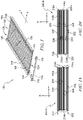
- FIG. 1 illustrates an example thermal management system 100 including a coldplate assembly 102 for circulating coolant to transfer heat away from one or more components disposed adjacent to the coldplate assembly 102.
- the coldplate assembly 102 includes a base plate 104 defining an inlet passage 105 and an outlet passage 106.
- the inlet and outlet passages 105, 106 extend longitudinally (y-axis) along opposite sides of a body of the base plate 104.
- the inlet passage 105 receives coolant through an inlet opening 112, while the outlet passage 106 expels the coolant through an outlet opening 114.
- the base plate 104 defines a plurality of intermediate passages 108 disposed between the inlet and outlet passages 105, 106 and arranged to circulate coolant to transfer heat away from one or more components disposed adjacent to the coldplate assembly 102.
- the intermediate passages 108 extend parallel to one another and parallel to the inlet and outlet passages 105, 106 along the length (longitudinally, or along the y-axis) of the base plate 104.
- the intermediate passages 108 may be spaced apart from one another and from the inlet and outlet passages 105, 106 along a width (laterally, or along the x-axis) of the base plate 104.
- the intermediate passages 108 are evenly distributed over the entire area of the base plate 104.
- the intermediate passages 108 of the base plate 104 include openings 122 arranged to receive and expel coolant.
- a seal plate 110 may connect to a first end 124 of the base plate 104, where the first end 124 of the base plate 104 is disposed opposite a second end 126 of the base plate 104.
- the seal plate 110 may optionally include seal plate inlet and outlet openings 116, 118 that align with a corresponding one of the inlet opening 112 and the outlet opening 114 of the base plate 104. In other embodiments, the seal plate 110 may only extend to cover the openings 122, but not the inlet opening 112 and the outlet opening 114 of the base plate 104.
- the cross-sectional shape of the intermediate passages 108 of a given coldplate assembly 102 may be designed to accommodate a particular purpose of the coldplate assembly 102. In some instances, a specific application of a given coldplate assembly 102 may benefit from maximizing heat transfer efficiency by maximizing a surface area, i.e., a perimeter in two dimensions, of the cross-section of the intermediate passage 108 that comes in direct contact with coolant. Examples of such intermediate passages 108 are shown in the illustrative embodiment.
- the base plate 104 may be formed using a near-net extrusion of parallel flow holes.
- the base plate 104 may include twelve intermediate passages 108 (or slots) in addition to the inlet and outlet passages 105, 106.
- the base plate 104 may further be formed (e.g., machined) to include one or more transverse passages that connect the intermediate passages 108 and/or the inlet and outlet passages 105, 106.
- the transverse passages may connect together several sets of parallel-flow intermediate passages 108. Accordingly, depending on arrangement of the transverse passages with respect to one or more intermediate passages 108 of the base plate 104, a given coldplate assembly 102 may be configured to provide either high rate of coolant flow or high coolant dwell time, as discussed further below.
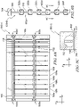
- FIG. 2A illustrates an example diagram 200-A of coolant flow pattern in a coldplate 102 a .
- the inlet and outlet passages 105, 106 and the intermediate passages 108 of the coldplate 102 a are interconnected with one another by a plurality of transverse passages 214 arranged about each of the first end 124 and the second end 126 of the base plate 104.
- the transverse passages 214 extend along portions of the width (x-axis) of the base plate 104 in a lateral direction perpendicular to the inlet and outlet passages 105, 106 and to the intermediate passages 108.
- coolant enters 202 the inlet passage 105 about the first end 124 of the base plate 104.
- the coolant flows 204 from the first end 124 to the second end 126 of the base plate 104.
- the coolant enters a first transverse passage 214 a about the second end 126 of the base plate 104.
- the first transverse passage 214 a connects together the inlet passage 105 and a first subset of intermediate passages 108.
- the coolant enters each of the first subset of intermediate passages 108 via the first transverse passage 214 a at or about a same time.
- the first transverse passage 214 a directs 206 the coolant flow from the second end 126 to a second transverse passage 214 b disposed at the first end 124 of the base plate 104.
- the second transverse passage 214 b connects the first subset of intermediate passages 108 and a second subset of intermediate passages 108.
- coolant flowing through each of the first subset of intermediate passages 108 is directed to the second subset of intermediate passages 108.
- the coolant enters each of the second subset of intermediate passages 108 via the second transverse passage 214 b at or about a same time.
- the second transverse passage 214 b directs 208 the coolant flow from the first end 124 to a third transverse passage 214 c disposed at the second end 126 of the base plate 104.
- the third transverse passage 214 c connects the second subset of intermediate passages 108 and the outlet passage 106 of the base plate 104.
- the third transverse passage 214c directs 210 the coolant flowing through each of the second subset of intermediate passages 108 to the outlet passage 106 that expels 212 the coolant.
- the example arrangement of the diagram 200-A includes three transverse passages 214 that interconnect the inlet and outlet passages 105, 106 via the intermediate passages 108 to create a four-pass coldplate 102 a , in which two of the passes have six parallel flow runs.
- the exemplary arrangement of the diagram 200-A may be considered a "high-flow" arrangement.
- FIG. 2B illustrates an example diagram 200-B of coolant flow pattern in a coldplate 102 b .
- the inlet and outlet passages 105, 106 and the intermediate passages 108 of the coldplate 102 b are interconnected with one another by a plurality of transverse passages 236 arranged about each of the first end 124 and the second end 126 of the base plate 104.
- the transverse passages 236 extend along portions of the width (x-axis) of the base plate 104 in a lateral direction perpendicular to the inlet and outlet passages 105, 106 and to the intermediate passages 108.
- coolant enters 220 the base plate 104 at the inlet passage 105 about the first end 124 and exits 234 the base plate 104 at the outlet passage 106 about the first end 124.
- the coolant flows 222 along the inlet passage 105 to a first transverse passage 236 a that connects together the inlet passage 105 and a first subset of intermediate passages 108.
- the first subset of intermediate passages 108 directs 224 coolant to a second subset of intermediate passages 108 via a second transverse passage 236 b connected therebetween.
- the second subset of intermediate passages 108 direct 226 coolant from the second subset of intermediate passages 108 to a third subset of intermediate passages 108 via a third transverse passage 236 c .
- the third subset of intermediate passages 108 direct 228 coolant to a fourth subset of intermediate passages 108 via a fourth transverse passage 236 d .
- a fifth transverse passage 236 e receives 230 coolant from each of the fourth subset of intermediate passages 108 and, subsequently, directs 232 the flow to the outlet passage 106 where the coolant exits 234 the base plate 104.
- the example arrangement of the diagram 200-B includes five transverse passages 236 that connect the inlet and outlet passages 105, 106 via the intermediate passages 108 to create a six-pass coldplate 102 b .
- the arrangement of the diagram 200-B includes four subsets of intermediate passages 108 having parallel flow runs, with each set including three intermediate passages 108.
- a larger number of subsets of intermediate passages 108 and transverse passages 236 increases an amount of time that the coolant spends within the coldplate 102 b (also refered to as "dwell time").
- Dwell time may be measured as, for example, a time period between a first time when the coolant enters 220 the coldplate 102 b and a second time when the coolant exits 234 the coldplate 102 b . Accordingly, a dwell time of the coolant in the example arrangement of the diagram 200-B may be greater than a dwell time of the coolant in the example arrangement of the diagram 200-A.
- FIG. 3 illustrates a plug 300 configured to regulate the flow of coolant in the coldplate assembly 102.
- the plug 300 may include a first end portion (head) 302 and a second end portion 304 connected with one another by a connecting rod (shaft) 306.
- the connecting rod 306 may extend longitudinally from a center of an inner side 308 of the second end portion 304 to a center of an inner side 310 of the first end portion 302.
- the plug 300 may be configured to be disposed within a transverse passage 402 of the base plate 104 to direct the flow of coolant.
- the drive slot 314 is configured to receive a portion of a tool, e.g., a tip of a blade of a screwdriver, during insertion of the plug 300 into the transverse passage.
- the first end portion 302 defines a seal slot 316 disposed about a body 320 of the first end portion 302 extending between the inner and outer sides 310, 312.
- the seal slot 316 may be configured to receive a seal 318.
- FIG. 4 illustrates an example arrangement 400 for the coldplate assembly 102 including the transverse passage 402.
- the transverse passage 402 extends laterally with respect to the inlet and outlet passages 105, 106 and the intermediate passages 108, along the width (x-axis) of the base plate 104 about the first end 124.
- the transverse passage 402 extends through to a first side 404 of the base plate 104 to define an opening 406 therein. While the transverse passage 402 shown in FIG. 4 extends from the first side 404 of the base plate 104, the design is not so limited. As described in reference to at least FIGS.
- the transverse passage 402 of the base plate 104 may extend between one or more of the first side 404 of the base plate 104 and a second side (not illustrated) of the base plate 104 disposed opposite the first side 404.
- the transverse passage 402 may intersect any number of the inlet and outlet passages 105, 106 and the intermediate passages 108 (e.g., the transverse passage 402 may intersect only one of the inlet passage 105 and the outlet passage 106 and only a subset of the intermediate passages 108).
- the transverse passage 402 may be configured to receive the plug 300.
- the first end portion 302 of the plug 300 (with or without the seal 318) may be sized to seal the transverse passages opening 406 about the first side 404 of the base plate 104 to prevent fluid flow therethrough.
- the second end portion 304 of the plug 300 may be sized to seal a first transverse passage portion 407 of the transverse passage 402 that extends between an inner wall 409 of the inlet passage 105 and an outer wall 411 of the intermediate passage 108 immediately adjacent to the inlet passage 105.
- the body 320 of first end portion 302 is sized such that the outer side 312 of the first end portion 302 is flush with the first side 404 of the base plate 104 and the inner surface 310 of the first end portion 302 is flush with an outer wall 413 of the inlet passage 105.
- the coolant may enter 408 the inlet passage 105 through a connector fitting 405 configured to connect the coldplate assembly 102 to one or more other components (not illustrated) of the thermal management system 100, such as, but not limited to, a coolant pump, a water pump, a heat exchanger, and a cooling tower.
- the connecting rod 306 of the plug 300 may extend across a width (x-axis) of the inlet passage 105 from the outer wall 413 of the inlet passage 105 to the inner wall 409 of the inlet passage 105.
- the first end portion 302 of the plug 300 prevents coolant flow between the outer wall 413 of the inlet passage 105 and the first side of the base plate 104.
- the second end portion 304 of the plug 300 prevents coolant flow between the inner wall 409 of the inlet passage 105 and the outer wall 411 of the intermediate passage 108 immediately adjacent to the inlet passage 105.
- the coolant may subsequently pass 410, 412 through the intermediate passages 108 having parallel flow.
- the second end portion 304 of the plug 300 prevents coolant flow from the intermediate passages 108 into the inlet passage 105.
- additional components may be used to redirect coolant flowing the in the intermediate passages 108.
- FIG. 5 illustrates an isometric projection view 500 of a valve 502 for controlling flow of coolant through the coldplate assembly 102.
- the valve 502 is illustratively embodied as a rotating valve, it is contemplated the valve 502 could be alternatively embodied as a valve that actuates with linear movement or a combination of rotational and linear movements.
- the valve 502 includes a first end portion 504 and a second end portion 506 connected with one another using a connecting rod 508.
- the first end portion 504 of the valve 502 is substantially similar to the first end portion 302 of the plug 300 described with reference to FIGS. 3 and 4 .
- the second end portion 506 of the valve 502 includes a protrusion in the form of an elongated spine member 510 having a first spine side 512 and a second spine side 514, where the second spine side 514 is disposed opposite the first spine side 512.
- Each of the first and second spine sides 512, 514 define a plurality of additional protrusions, such as blocking members 516 (516 a , 516 b , 516 c ) and/or parallel flow members 522.
- the first spine side 512 of the second end portion 506 defines a first blocking member 516 a about a first end 518 of the elongated spine member 510 and a second blocking member 516b about a second end 520 of the elongated spine member 510, where the second end 520 of the elongated spine member 510 is disposed opposite the first end 518 of the elongated spine member 510.
- the second spine side 514 defines a third blocking member 516 c positioned about a center of the second spine side 514 of the elongated spine member 510.
- Each of the blocking members 516 is illustratively formed as a semicircular protrusion having a flat side that connects to one of the first and second spine sides 512, 514 and an arc side that extends outwardly from the corresponding spine side 512, 514.
- the blocking members 516 may be shaped such that, when the valve 502 is disposed within the transverse passage 402 of the base plate 104, the blocking members 516 regulate the flow through the intermediate passages 108 and the transverse passage 402 by selectively completing portions of the geometry of the intermediate passages 108 and/or the transverse passage 402. It will be appreciated by those skilled in the art that the number and positioning of the blocking members 516 shown in FIG. 5 are merely exemplary, and that other embodiments of the value 502 may use other numbers and/or positioning of blocking members 516.
- a plurality of parallel flow members 522 extend along a bottom 524 of the elongated spine member 510 (opposite a top 526 of the elongated spine member 510) in a perpendicular manner to the elongated spine member 510.
- Each of the parallel flow members 522 and the elongated spine member 510 thus, define a T-shape in cross-section (which can best be seen in FIG. 7C ).
- the parallel flow members 522 may be shaped such that, when the valve 502 is disposed within the transverse passage 402 of the base plate 104, the parallel flow members 522 regulate the flow through the intermediate passages 108 and the transverse passage 402 by selectively completing portions of the geometry of the intermediate passages 108 and/or the transverse passage 402. It will be appreciated by those skilled in the art that the number and positioning of parallel flow members 522 shown in FIG. 5 are merely exemplary, and that other embodiments of the value 502 may use other numbers and/or positioning of parallel flow members 522.
- FIG. 6 is a simplified diagram 600 illustrating placement of the valve 502 of FIG. 5 within the coldplate assembly 102.
- the base plate 104 includes a transverse passage 602 that extends laterally with respect to the inlet passage 105 and the intermediate passages 108 (including intermediate passages 108 a , 108 b , 108 c , 108 d , 108 e , 108 f , 108 g ), in a similar manner to the transverse passage 402 discussed above with reference to FIG. 4 .
- the transverse passage 602 intersects the inlet passage 105 and the intermediate passages 108 to define a series of junctions.
- the transverse passage 602 defines an opening 606 where the transverse passage 602 intersects a side of the base plate 104.
- the transverse passage 602 is arranged to receive the valve 502 such that the first end portion 504 of the valve 502 seals the opening 606 to prevent flow of coolant through the opening 606.
- the connecting rod 508 joining together the first and second end portions 504, 506 of the valve 502 extends across a width of the inlet passage 105 to permit coolant flow through the inlet passage 105.
- each of the parallel flow members 522 aligns with one of the intermediate passages 108 a , 108 b , 108 c , 108 d , 108 e , 108 f .
- each of the parallel flow members 522 is positioned in a junction formed between the transverse passage 602 and one of the intermediate passages 108 a , 108 b , 108 c , 108 d , 108 e , 108 f .
- the first blocking member 516 a of the valve 502 is disposed within a portion of the transverse passage 602 between the inlet passage 105 and the intermediate passage 108 a
- the second blocking member 516 b of the valve 502 is disposed within a portion of the transverse passage 602 between the intermediate passage 108 f and the intermediate passage 108 g
- the third blocking member 516 c of the valve 502 is disposed within a portion of the transverse passage 602 between the intermediate passage 108 c and the intermediate passage 108 d .
- valve 502 may be rotated between several different orientations within the transverse passage 602 to selectively redirect the flow of coolant in the base plate 104.
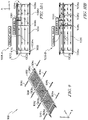
- FIG. 7A illustrates an example arrangement 700-A of a plurality of valves 502 (502 a , 502b, 502 c , 502 d ) positioned within a portion of the base plate 104 to control flow of coolant through the base plate 104.
- Each of the valves 502 has a similar construction to that described above with reference to FIG. 5 .
- the base plate 104 defines the inlet passage 105, the outlet passage 106, and a plurality of intermediate passages 108 between the inlet and outlet passages 105, 106.
- FIG. 7A illustrates an example arrangement 700-A of a plurality of valves 502 (502 a , 502b, 502 c , 502 d ) positioned within a portion of the base plate 104 to control flow of coolant through the base plate 104.
- Each of the valves 502 has a similar construction to that described above with reference to FIG. 5 .
- the base plate 104 defines the inlet passage 105, the
- the base plate 104 also defines a pair of transverse passages 702, 704 (which are similar to the transverse passages 402, 602 described with reference to FIGS. 4 and 6 ).
- the valve 502 a is disposed in one end of the transverse passage 702, while the valve 502 c is disposed in the other end of the transverse passage 702, such that the respective second ends of the valves 502 a , 502 c abut one another.
- the valve 502 b is disposed in one end of the transverse passage 704, while the valve 502 d is disposed in the other end of the transverse passage 704, such that the respective second ends of the valves 502 b , 502 d abut one another.
- each of the valves 502 is arranged in a first position in which the parallel flow members 522 are orientated away from the intermediate passages 108.
- FIG. 7B illustrates a bottom view 700-B (as seen from a bottom 742 of the base plate 104) of the valve 502 a disposed in the first position.
- the valve 502 a includes a connecting rod 508 that extends across the inlet passage 105 to permit unobstructed coolant flow through the inlet passage 105.
- the connecting rod 508 connects the first end portion 504 and the second end portion 506.
- the elongated spine member 510, the first and second blocking members 516 a , 516 b disposed on the first spine side 512, and the third blocking member 516 c disposed on the second spine side 514 redirect the flow of coolant through the base plate 104.
- the connecting rod 508 of the first valve 502 a permits coolant to flow past the connecting rod 508 through the inlet passage 105. While the first blocking member 516 a of the first valve 502 a prevents the coolant from entering the first transverse passage 702 about the first spine side 512, coolant flow enters the first transverse passage 702 about the second spine side 514 of the first valve 502 a .
- the third blocking member 516 c of the first valve 502 a directs coolant through a first subset of the intermediate passages 108 toward the second transverse passage 704.
- the first blocking member 516 a of the second valve 502 b directs the coolant along the first spine side 512 of the second valve 502 b and toward a second subset of the intermediate passages 108.
- the second blocking member 516 b of the second valve 502 b then directs the flow of coolant through the second subset of intermediate passages 108, back toward the first transverse passage 702.
- the third blocking member 516 c of the first valve 502 a directs the coolant along the second spine side 514 of the first valve 502 a , along the second spine side 514 of the third valve 502 c , and toward a third subset of the intermediate passages 108.
- the third blocking member 516c of the third valve 502 c then directs the flow of coolant through the third subset of intermediate passages 108, back toward the second transverse passage 704.
- the second blocking member 516 b of the fourth valve 502 d directs the coolant along the first spine side 512 of the fourth valve 502 d and toward a fourth subset of the intermediate passages 108.
- the first blocking member 516 a of the fourth valve 502 d then directs the flow of coolant through the fourth subset of intermediate passages 108, back toward the first transverse passage 702.
- the third blocking member 516 c of the third valve 502 c directs the coolant along the second spine side 514 of the third valve 502 c and toward the outlet passage 106.
- the connecting rod 508 of the third valve 502 c permits coolant to flow past the connecting rod 508 through the outlet passage 106.
- the first blocking member 516 a of the third valve 502 c prevents the coolant from reentering the transverse passage 702 along the first spine side 512 of the third valve 502 c .
- FIG. 7C illustrates a cross-sectional view 700-C showing a cross-section of the first valve 502 a , taken along line 7C-7C of FIG. 7B .
- the intermediate passage 108 of the base plate 104 is defined between a first surface 748 and a second surface 740 of a bottom 742 of the base plate 104.
- the top 526 of the elongated spine member 510 abuts the second surface 740 of the base plate 104, presenting a barrier to the flow 744, 746 of coolant through the intermediate passage 108.
- the elongated spine member 510 prevents (or at least impedes) coolant from flowing from the first spine side 512 to the second spine side 514, or vice versa.
- coolant is permitted to flow along the first spine side 512 between intermediate passages 108 of the base plate 104, at least until the coolant encounters the first blocking member 516 a or the second blocking member 516 b .
- coolant is permitted to flow along the second spine side 514 between intermediate passages 108 of the base plate 104, at least until the coolant encounters the third blocking member 516 c .
- FIG. 8A illustrates an example arrangement 800-A of a plurality of valves 502 (502 a , 502 b , 502 c , 502 d ) positioned within a portion of the base plate 104 to control flow of coolant through the base plate 104.
- Each of the valves 502 has a similar construction to that described above with reference to FIG. 5 .
- the base plate 104 defines the inlet passage 105, the outlet passage 106, and a plurality of intermediate passages 108 between the inlet and outlet passages 105, 106.
- FIG. 8A illustrates an example arrangement 800-A of a plurality of valves 502 (502 a , 502 b , 502 c , 502 d ) positioned within a portion of the base plate 104 to control flow of coolant through the base plate 104.
- Each of the valves 502 has a similar construction to that described above with reference to FIG. 5 .
- the base plate 104 defines the inlet passage 105
- the base plate 104 also defines a pair of transverse passages 702, 704 (which are similar to the transverse passages 702, 704 described with reference to FIG. 7A ).
- the valve 502 a is disposed in one end of the transverse passage 702, while the valve 502 c is disposed in the other end of the transverse passage 702, such that the respective second ends of the valves 502 a , 502 c abut one another.
- the valve 502 b is disposed in one end of the transverse passage 704, while the valve 502 d is disposed in the other end of the transverse passage 704, such that the respective second ends of the valves 502 b , 502 d abut one another.
- the second and fourth valves 502 b , 502 d are arranged in the first position and function in the same manner discussed above with reference to FIG. 7A .
- the first and third valves 502 a , 502 c are arranged in a different second position in FIG. 8A (see also FIGS. 8B and 8C ).
- Each of the valves 502 may be rotated in its respective transverse passage 702, 704 between a number of different positions (including the first and second positions), for example, by using a tip of a screwdriver blade inserted into a drive slot on the first end 504 of the valve 502.
- the first end 504 of each valve 502 and/or a surrounding portion of the base plate 104 may contain indicia that indicate the position occupied the corresponding valve 502.
- FIGS. 8A-8C When the first and third valves 502 a , 502 c are arranged in the second position, shown in FIGS. 8A-8C , the parallel flow members 522 are positioned in the intermediate passages 108.
- the orientation of the first and third valves 502 a , 502 c in the second position is opposite (e.g., 180 degrees rotated from) the orientation of the first and third valves 502 a , 502 c when in the first position shown in FIGS. 7B and 7C .
- FIG. 8B illustrates a bottom view 800-B (as seen from a bottom 742 of the base plate 104) of the valve 502 a disposed in the second position.
- each of the parallel flow members 522 a , 522b, 522 c , 522d, 522 e , 522 f is positioned in a corresponding one of the intermediate passages 108 a , 108 b , 108 c , 108d, 108 e , 108 f (see FIG. 7A ).
- Each parallel flow member 522 a , 522b, 522 c , 522d, 522 e , 522f completes the geometry of the corresponding intermediate passage 108 a , 108 b , 108 c , 108 d , 108 e , 108 f , allowing coolant to flow through each intermediate passage 108, but preventing (or at least impeding) coolant from entering the transverse passage 702 in which the first valve 502 a is positioned.
- FIG. 8C illustrates a cross-sectional view 800-C showing a cross-section of the first valve 502 a , taken along line 8C-8C of FIG. 8B .
- the intermediate passage 108 of the base plate 104 is defined between a first surface 748 and a second surface 740 of a bottom 742 of the base plate 104.
- the parallel flow member 522 d completes the first surface 748 forming the top of the intermediate passage 108 d , thereby allowing coolant flow 802 along the intermediate passage 108 d .
- each of the remaining parallel flow members 522 a , 522 b, 522 c , 522 e , 522 f of the first valve 502 a functions in a similar manner with respect to the remaining intermediate passages 108 a , 108 b , 108 c , 108 e , 108 f .
- the first blocking member 516 a of the second valve 502 b directs the coolant along the first spine side 512 of the second valve 502 b and toward the intermediate passages 108 d , 108 e , 108 f .
- the second blocking member 516 b of the second valve 502 b then directs the flow of coolant through each of the intermediate passages 108 d , 108 e , 108 f , back toward the first valve 502 a .
- FIG. 9 illustrates an example arrangement 900 of the coldplate assembly 102, in which eight valves 904 a -904 h are arranged in pairs in each of four transverse passages 906 a -906 d of the base plate 902. Each of the eight valves 904 a -904 h can moved between a plurality of positions (including the first and second positions described above) to configure the coldplate assembly 102 for a variety of applications. While the arrangement 900 is illustrated in FIG. 9 as having four transverse passages 906 and eight valves 904, it is contemplated that any number of transverse passages and valves could be used. For instance, in some embodiments, a base plate may include eight or sixteen transverse passages configured to receive sixteen or thirty-two valves, respectively.
- FIGS. 10A and 10B illustrate two example flow paths 1000-A, 1000-B, respectively, for a coldplate 1002 configured to cool a component 1004.
- the coldplate 1002 may be readily changed between the flow path 1000-A and the flow path 1000-B by changing the position of certain of the valves.
- changing the coldplate 1002 between the flow path 1000-A and the flow path 1000-B may change a preheat area parameter indicative of an area of the coldplate 1002 travelled by coolant from an inlet passage 1008 prior to reaching the component 1004.
- the coldplate 1002 comprises a first transverse passage 1006 a extending along x-axis between the inlet passage 1008 and an outlet passage 1010 about a first end 1012 of the coldplate 1002.
- the coldplate 1002 also comprises a second transverse passage 1006 b extending along x-axis between the inlet passage 1008 and the outlet passage 1010 about a second end 1014 of the coldplate 1002.
- the coldplate 1002 also comprises a third transverse passage 1006 c and a fourth transverse passage 1006 d each extending along x-axis between the inlet passage 1008 and the outlet passage 1010 at intermediate positions between the first and second ends 1012, 1014 of the coldplate 1002.
- the cold plate comprises a plurality of intermediate passages 1016 extending parallel to the inlet and outlet passages 1008, 1010 and intersecting the first, second, third, and fourth transverse passages 1006 a , 1006 b , 1006 c , 1006 d .
- a pair of valves is disposed in each of the first, second, third, and fourth transverse passages 1006 a , 1006 b , 1006 c , 1006 d and functions in the manner discussed above with reference to FIGS. 5-8C .
- valves in transverse passage 1006 a and the valves in transverse passage 1006 b are each orientated in the first position (described above with reference to FIGS. 7A-7C ), while the valves in transverse passage 1006 c and the valves in transverse passage 1006 d are each orientated in the second position (described above with reference to FIGS. 8A-8C ).
- coolant is redirected laterally in the transverse passages 1006 a , 1006 b by the valves arranged in the first position.
- coolant does not travel in the transverse passages 1006 c , 1006 d , but continues flowing along the respective intermediate passages 1016 as directed by the valves arranged in the second position.
- coolant travels over and collects heat from approximately 85% of the total area of the coldplate 1002 before reaching the component 1004.
- valves in transverse passage 1006 c and the valves in transverse passage 1006 d are each re-orientated to the first position (described above with reference to FIGS. 7A-7C ), while valves in transverse passage 1006 a and the valves in transverse passage 1006 b remain orientated in the same first position.
- at least a portion of the coolant is redirected laterally in each of the transverse passages 1006 a , 1006 b , 1006 c , 1006 d by the valves arranged in the first position.
- valves in transverse passage 1006 c and the valves in transverse passage 1006 d are each re-orientated, as described above, manually by a user to change between the flow paths 1000-A and 1000-B.
- the valves in transverse passages 1006 c , 1006 d are re-orientated automatically (e.g., by a controller and electro-actuators) in response to thermal conditions of the matrix coldplate.
- FIGS. 11A and 11B a top view 1100-A and a side cross-sectional view 1100-B of one of the valves 502 disposed in a third position within a transverse passage 702 of the base plate 104 are illustrated.
- the valve 502 has a similar construction to that described above with reference to FIG. 5 .
- a first side 528 of each parallel flow member 522 of the valve 502 is positioned in the intermediate passage 108 corresponding to that parallel flow member 522
- a second side 530 of each parallel flow member 522 of the valve 502 is positioned out of the intermediate passage 108 corresponding to that parallel flow member 522 (best seen in the cross-section of FIG. 11B ).
- each parallel flow member 522 caps off the portion of the corresponding intermediate passage 108 faced by the parallel flow member 522. In this way, each parallel flow member 522 prevents (or at least impedes) a flow 746 of coolant approaching the valve 502 from a first side from either entering the transverse passage 702 or continuing along the intermediate passage 108 (when the valve is in the third position shown in FIG. 11B ).
- a flow 744 of coolant approaching the valve 502 from a second side is redirected from the intermediate passage 108 along the second spine side 514 of the valve 502, along the transverse passage 702. (In this way, the flows 744 of coolant shown in both FIGS. 7C and 11B behave in a similar manner, when the valve 502 is in the first or third position.)
- FIG. 11C a side cross-sectional view 1100-C of one of the valves 502 disposed in a fourth position within a transverse passage 702 of the base plate 104 is illustrated.
- the fourth position of the valve 502 is a "mirror image" of the third position flipped along z-axis direction of the coldplate assembly 102.
- each parallel flow member 522 of the valve 502 is positioned in the intermediate passage 108 corresponding to that parallel flow member 522, while the first side 528 of each parallel flow member 522 of the valve 502 is positioned out of the intermediate passage 108 corresponding to that parallel flow member 522.
- each parallel flow member 522 caps off the portion of the corresponding intermediate passage 108 faced by the parallel flow member 522.
- each parallel flow member 522 prevents (or at least impedes) a flow 744 of coolant approaching the valve 502, from the second side, from either entering the transverse passage 702 or continuing along the intermediate passage 108.
- FIGS. 12A-12D illustrate four exemplary flow paths 1200-A, 1200-B, 1200-C, and 1200-D, respectively, for the illustrative coldplate 1002.
- the structure of the illustrative coldplate 1002 is described above with reference to FIGS. 10A-B .
- the coldplate 1002 may be readily changed between any of the flow paths 1200-A, 1200-B, 1200-C, and 1200-D by changing the position of certain of the valves.
- both manual and automatic repositions of the valves to achieve various regions of parallel flow, serial flow, and/or blocked flow (and, thus, the various flow paths 1200-A, 1200-B, 1200-C, and 1200-D), is contemplated.
- FIG. 12A illustrates a flow path 1200-A of the coldplate 1002 in which all of the valves (positioned in each of the transverse passages 1006 a , 1006 b , 1006 c , 1006 d ) are arranged in the first position (described above with reference to FIGS. 7A-C ).
- a first coolant flow area 1212 of the coldplate 1002 is defined between the transverse passages 1006 a , 1006 c .
- each of the coolant flow areas 1212, 1214, and 1216 provides somewhat independent thermal management for one or more components (not illustrated) disposed adjacent to the respective flow area. Accordingly, temperature of the coolant circulated within each of the flow areas 1212, 1214, 1216 is largely unaffected by temperature changes in the other flow areas.
- FIG. 12B illustrates a flow path 1200-B of the coldplate 1002 similar to FIG. 12A , but in which the valves in the transverse passage 1006 d have been arranged in the second position (described above with reference to FIGS. 8A-C ).
- coolant is prevented (or largely impeded) from flowing along the transverse passage 1006 d and instead flows along the intermediate passages 1008 between the through groves 1006 b and 1006 c .
- the flow areas 1214 and 1216 discussed with reference to FIG. 12A are joined together to create a new, larger flow area 1218, defined between the transverse passages 1006 b , 1006 c .
- the flow area 1218 is able to operate somewhat independently of the flow area 1212, such that the temperature of the coolant circulated within each of the flow areas 1212, 1218 is largely unaffected by temperature changes in the other flow area.
- FIG. 12C illustrates a flow path 1200-C of the coldplate 1002 similar to FIG. 12A , but in which the valves in the transverse passage 1006c have been arranged in the second position (described above with reference to FIGS. 8A-C ).
- coolant is prevented (or largely impeded) from flowing along the transverse passage 1006 c and instead flows along the intermediate passages 1008 between the through groves 1006 a and 1006 c .
- the flow areas 1212 and 1214 discussed with reference to FIG. 12A are joined together to create a new, larger flow area 1220, defined between the transverse passages 1006 a , 1006 d .
- the flow area 1220 is able to operate somewhat independently of the flow area 1216, such that the temperature of the coolant circulated within each of the flow areas 1216, 1220 is largely unaffected by temperature changes in the other flow area.
- FIG. 12D illustrates a flow path 1200-D of the coldplate 1002 similar to FIG. 12A , but in which the valves in the both of the transverse passages 1006 c , 1006 d have been arranged in the second position (described above with reference to FIGS. 8A-C ).
- coolant is prevented (or largely impeded) from flowing along the transverse passages 1006 c , 1006 d and instead flows along the intermediate passages 1008 between the through groves 1006 a and 1006 b .
- the flow path 1200-D is similar to the flow path 1000-A discussed above with reference to FIG. 10A .
- Additional exemplary flow paths for the coldplate 1002 can be created by moving one or more of the valves of the coldplate 1002 into the third and/or fourth positions described above with reference to FIGS. 11A-C .
- the valves positioned in the transverse passage 1006 d were arranged in the fourth position of FIG. 11C (rather than the first position of FIGS.
- the valves positioned in the transverse passage 1006 d would block the flow of coolant into the portions of the intermediate passages 1008 extending between the transverse passages 1006 b , 1006 d , thereby converting the area 1216 into a "dry area" with no coolant flow (while permitting the flow areas 1212, 1214, 1220 to operate as described above).
- the valves positioned in the transverse passage 1006 d were arranged in the third position of FIGS. 11A-B
- the valves positioned in the transverse passage 1006 c were arranged in the fourth position of FIG.
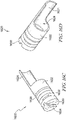
- FIGS. 13A-B illustrate isometric views 1300-A and 1300-B, respectively, of another illustrative embodiment of a valve 1302.
- the valve 1302 defines a body 1316 having, for example, a cylindrical shape.
- a drive slot 1318, defined in a proximal end portion 1304 of the body 1316, is configured to receive a portion of a hand tool (not illustrated), such that the valve 1302 may be re-oriented with respect to base plate 1400 of a coldplate assembly.
- a distal end portion 1306 of the body 1316 comprises a number of protrusions, including a center ridge 1310, a first rim 1312 a , and a second rim 1312 b .
- a first depression 1308 a and a second depression 1308 b are defined in the distal end portion 1306 of the body 1316 to either side of the center ridge 1310.
- the first depression 1308 a is defined between the center ridge 1310 and the first rim 1312 a
- the second depression 1308b is defined by the center ridge 1310 and the second rim 1312 b .
- FIG. 14 illustrates a coldplate assembly including the valve 1302 for controlling coolant flow within the base plate 1400.
- the base plate 1400 defines a first intermediate passage 1402 and a second intermediate passage 1404 extending longitudinally and disposed adjacent one another.
- the first intermediate passage 1402 extends parallel to the second intermediate passage 1404.
- the first intermediate passage 1402 and the second intermediate passage 1404 extend parallel to an outlet passage 1408 and/or an inlet passage (not illustrated) arranged to expel or deliver coolant to the base plate 1400, respectively.
- the valve 1302 is received in a transverse passage 1406 that extends from a top surface 1410 of the base plate 1400 toward a bottom of the base plate 1400 (but does not reach or pass through the bottom of the base plate 1400).
- the transverse passage 1406 intersects the first intermediate passage 1402 and the second intermediate passage 1404 define in the base plate 1400.
- the transverse passage 1406 is a counterbore opening defining a ledge 1414 arranged to receive a corresponding lip 1314 disposed around a circumference of the body 1316 of the valve 1302.
- each of the first depression 1308 a and the second depression 1308 b are sized to correspond to the geometry of the first intermediate passage 1402 and the second intermediate passage 1404, respectively.
- the center ridge 1310 is sized to span the area between the first intermediate passage 1402 and the second intermediate passage 1404.
- the valve 1302 may be movable between at least two positions to control coolant flow through and between the first intermediate passage 1402 and the second intermediate passage 1404.
- FIGS. 15A-C illustrate the valve 1302 movable between a plurality of positions to control coolant flow patterns within a base plate 1400.
- FIG. 15A illustrates an example configuration 1500-A of the base plate 1400 including the valve 1302 disposed in a first position within the transverse passage 1406. In this first position, the first depression 1308 a of the valve 1302 is aligned longitudinally with the first intermediate passage 1402 and the second depression 1308 b of the valve 1302 is aligned with the second intermediate passage 1404.
- the valve 1302 is in the first position shown in FIG. 15A , coolant is permitted to flow through the first intermediate passage 1402 relatively unimpeded by the valve 1302, and coolant is likewise permitted to flow through the second intermediate passage 1404 relatively unimpeded by the valve 1302.
- FIG. 15B illustrates an example configuration 1500-B of the base plate 1400 including the valve 1302 disposed in a second position within the transverse passage 1406.
- the valve 1302 has been rotated 90 degrees within the transverse passage 1406, to change from configuration 1500-A to configuration 1500-B.
- the first depression 1308 a extends between and interconnects adjacent portions of the first and second intermediate passages 1402, 1404, while the second depression 1308 b extends between and interconnects other adjacent portions of the first and second intermediate passages 1402, 1404.
- the first depression 1308 a redirects coolant from the first intermediate passage 1402 to the second intermediate passage 1404 (or vice versa, depending on flow directions).
- the second depression 1308 b redirects coolant from the second intermediate passage 1404 to the first intermediate passage 1402 (or vice versa, depending on flow directions).
- FIG. 15C illustrates an example configuration 1500-C of the base plate 1400 including the valve 1302 disposed in a third position within the transverse passage 1406.
- the valve 1302 has been rotated 45 degrees within the transverse passage 1406, to change from either configuration 1500-A or 1500-B to configuration 1500-C.
- the first and second depressions 1308 a , 1308 b are each positioned diagonally (non-parallel and non-perpendicular) to the first and second intermediate passages 1402, 1404, such that neither the first depression 1308 a nor the second depression 1308 b intersects more than one segment of the first and second intermediate passages 1402, 1404.
- no coolant flow is permitted through the first and second depressions 1308 a , 1308 b (or through the first and second intermediate passages 1402, 1404) when the valve 1302 is in the third position.
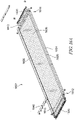
- FIGS. 16A-D illustrate portions of yet another embodiment of a coldplate 1602 according to the present disclosure.
- the coldplate 1602 includes a base plate 1604 of similar construction to the base plates described above (e.g. base plate 104).
- the base plate 1604 includes an inlet passage 1605, an outlet passage 1606, and a plurality of intermediate passages 1608 disposed between the inlet and outlet passages 1605, 1606 and arranged to circulate coolant to transfer heat away from one or more components disposed adjacent to the coldplate assembly 102.
- the intermediate passages 1608 extend parallel to one another and parallel to the inlet and outlet passages 1605, 1606 along the length (longitudinally, or along the y-axis) of the base plate 1604 and are spaced apart from one another and from the inlet and outlet passages 1605, 1606 along a width (laterally, or along the x-axis) of the base plate 1604.
- the base plate 1604 also includes transverse passages 1610 that intersect and connect at least some of the intermediate passages 1608 and the inlet and outlet passages 1605, 1606 to one another. As discussed above, this transverse passages 1610 may be machined (e.g., milled) into the extruded base plate 1604 including the intermediate passages 1608 and the inlet and outlet passages 1605, 1606. In the illustrative embodiment shown in FIG. 16A , one transverse passage 1610 is arranged near a first end 1612 of the base plate 1604, while another transverse passage 1610 is arranged near a second end 1612 of the base plate 1604.
- the coldplate 1602 further includes a plurality of valves 1620 (with four such valves 1620 a , 1620 b , 1620 c , and 1620 d being labelled in FIG. 16B ).
- a plurality of valves 1620 with four such valves 1620 a , 1620 b , 1620 c , and 1620 d being labelled in FIG. 16B .
- two valves 1620 are provided for each intermediate passage 1608 (one valve 1620 at the first end 1612 of the intermediate passage 1608, and another valve 1620 at the second end 1614 of the intermediate passage 1608).
- FIG. 16B a more detailed exploded view of the first end 1612 of the coldplate 1602 is illustrated.
- the coldplate 1602 further includes a plurality of valves 1620 (with four such valves 1620 a , 1620 b , 1620 c , and 1620 d being labelled in FIG. 16B ).
- two valves 1620 are provided for each intermediate passage 1608
- a generally cylindrical bore 1618 is provided at each end 1612, 1614 of each intermediate passage 1608 for receiving a corresponding valve 1620.
- the transverse passage 1610 intersects the cylindrical bores 1618 of each intermediate passage 1608 at one of the ends 1612, 1614.
- each valve 1620 has a generally cylindrical body 1622.
- a protrusion 1624 extends from a distal end 1626 of the body 1622.
- the protrusion 1624 is shaped as a cylindrical wall segment.
- the valve 1620 may include a gasket 1628 seated in a circumferential groove of the body 1622 and configured to seal one of the cylindrical bores 1618 of the base plate 1604 when the valve is positioned in that cylindrical bore 1618.
- the valve 1620 also includes a head 1630 connected to a proximal end of the body 1622 via a neck 1632.
- the neck 1632 is of smaller diameter than the body 1622 and the head 1630 and includes one or more surfaces configured to engage a lock clip 1640 (see FIG. 16B , discussed further below). Additionally, in the illustrative embodiment, the head 1630 includes a drive slot 1634 configured to receive a portion of a tool, e.g., a tip of a blade of a screwdriver, during insertion or adjustment (e.g., rotation) of the valve 1620 in the cylindrical bore 1618.
- a tool e.g., a tip of a blade of a screwdriver
- each of the valves 1620 may be independently adjusted (e.g. rotated) between a number of different positions to adjust the flow behavior of the coldplate 1602.
- the valve 1620 a is arranged in a first position relative to the cold plate 1602.
- the protrusion 1624 faces the inlet passage 1605 of the coldplate 1602 and prevents coolant flow between the corresponding intermediate passage 1608 (in which the valve 1620 is positioned) and a section of the transverse passage 1610 extending away from the corresponding intermediate passage 1608 toward the inlet passage 1605.
- the valve 1620 redirects coolant flow between the corresponding intermediate passage 1608 and a section of the transverse passage 1610 extending away from the corresponding intermediate passage 1608 toward the outlet passage 1606.
- the valves 1620 d is arranged in a second position relative to the cold plate 1602.
- the protrusion 1624 faces the outlet passage 1606 of the coldplate 1602 and prevents coolant flow between the corresponding intermediate passage 1608 (in which the valve 1620 is positioned) and a section of the transverse passage 1610 extending away from the corresponding intermediate passage 1608 toward the outlet passage 1606.
- the valve 1620 redirects coolant flow between the corresponding intermediate passage 1608 and a section of the transverse passage 1610 extending away from the corresponding intermediate passage 1608 toward the inlet passage 1605.
- the valves 1620 are also able to be moved to a third position, exemplified by the valves 1620 b and 1620 c shown in FIG. 16B .
- the protrusion 1624 faces an upper surface of the base plate 104 and does not block coolant flow to any section of the transverse passage 1610.
- the valve 1620 allows relatively unimpeded coolant flow along the transverse passage 1610 and also allows coolant flow between the transverse passage 1610 and the corresponding intermediate passage 1608 (in which the valve 1620 is positioned).
- Each of the plurality of valves 1620 of the coldplate 1602 may be independently arranged in any of these (and other) positions, providing a high degree of flexibility and customization of the coldplate 1602 for various applications.
- FIGS. 16A-B also illustrate a lock clip 1640 that may be used with the coldplate 1602 to hold each of the valves 1620 in one of a number of predetermined positions.
- the lock clip 1640 includes a number of teeth 1642 configured to be received in corresponding passages 1644 in the base plate 1604.
- one such passage is positioned between each pair of intermediate passages 1608 (specifically, between adjacent cylindrical bores 1618 of the intermediate passages 1608).
- each tooth 1642 of the lock clip 1640 engages at least one surface on the neck 1632 of an associated valve 1620, such that an interference fit between the at least one surface of the neck 1632 and tooth 1642 prevents (or at least impedes) rotation of the valve 1620 away from its present position. It is contemplated that any of the valves described in the present disclosure may be provided with similar position locking mechanism.
Landscapes
- Engineering & Computer Science (AREA)
- Physics & Mathematics (AREA)
- Thermal Sciences (AREA)
- Mechanical Engineering (AREA)
- General Engineering & Computer Science (AREA)
- Microelectronics & Electronic Packaging (AREA)
- Chemical & Material Sciences (AREA)
- Combustion & Propulsion (AREA)
- Cooling Or The Like Of Semiconductors Or Solid State Devices (AREA)
- Details Of Valves (AREA)
- Cooling Or The Like Of Electrical Apparatus (AREA)
Abstract
Description
- The present disclosure relates to systems and methods for thermal management using matrix coldplates.
- Electrical and mechanical components generate heat during operation. Excess heat may cause components to cease operating or to operate incorrectly. Accordingly, having an efficient heat transfer strategy is an important factor in ensuring component reliability and effectiveness.
- A typical coldplate may comprise copper tubing formed by way of computer numerical control (CNC). The tubing may be pressed or flattened into a base plate to closely match a unique shape of the base plate. Further, the tubing may be epoxied, or otherwise firmly mated to the base plate. The tubing may then be further re-machined. Adapters may be brazed onto copper tube for customer's fittings.
- The base plate may comprise an aluminum plate machined to define a plurality of copper tube passages, mounting holes, as well as, machining-removed sections to reduce overall weight. Accordingly, a given coldplate may be shaped into a particular configuration to fit a specific application. Once formed, however, the coldplate design may be difficult to adapt for heat transfer applications different from the one for which it was originally designed.
- According to one aspect of the present disclosure, a method may comprise directing a flow of coolant through a coldplate comprising a plurality of parallel passages by selectively connecting portions of the parallel passages to one another to create one or more regions of parallel flow, serial flow, or blocked flow in the coldplate.
- In some embodiments, each of the plurality of passages may open to an end surface of the coldplate. Selectively connecting portions of the parallel passages may comprise applying a seal plate to the end of the coldplate that connects at least some of the parallel passages to one another.
- In some embodiments, applying the seal plate to the end of the coldplate may connect a first subset of the parallel passages to one another and connect a second subset of the parallel passages to one another.
- In some embodiments, selectively connecting portions of the parallel passages may comprise machining a plurality of transverse passages into the cold plate such that each of the transverse passages intersects at least some of the parallel passages.
- In some embodiments, the method may further comprise extruding the coldplate to form the plurality of parallel passages, prior to machining the plurality of transverse passages.
- In some embodiments, at least one of the plurality transverse passages may intersect only a subset of the parallel passages.
- In some embodiments, selectively connecting portions of the parallel passages may comprise positioning a valve at a junction formed where one of the transverse passages intersects one of the parallel passages.
- In some embodiments, positioning the valve at the junction may comprise positioning the valve in one of: (i) a first position in which the valve redirects the flow of coolant from the parallel passage to the transverse passage, (ii) a second position in which the valve permits the flow of coolant in the parallel passage and blocks the flow of coolant in the transverse passage, and (iii) a third position in which the valve blocks the flow of coolant in both the parallel passage and the transverse passage.
- In some embodiments, the method may further comprise moving the valve from one of the first, second, and third positions to another of the first, second, and third positions to change the flow of coolant through the coldplate.
- In some embodiments, the method may further comprise adjusting the position of the valve to change the flow of coolant through the coldplate.
- In some embodiments, the position of the valve may be adjusted automatically in response to the thermal conditions of the coldplate.
- According to another aspect of the present disclosure, a coldplate assembly may comprise a base plate defining an inlet passage, an outlet passage, a first intermediate passage, a second intermediate passage, and a transverse passage. The first and second intermediate passages may each be disposed between the inlet passage and the outlet passage, and the transverse passage may be arranged to intersect the first intermediate passage to define a first junction and to intersect the second intermediate passage to define a second junction. The coldplate assembly may further comprise a valve comprising at least one protrusion. The valve may be moveable within the transverse passage between at least two of: (i) a first position in which the at least one protrusion is disposed with respect to the first and second junctions to redirect a flow of coolant from the first intermediate passage to the second intermediate passage; (ii) a second position in which the at least one protrusion is disposed with respect to the first junction to direct the flow of coolant past the first junction along the first intermediate passage; and (iii) a third position in which the at least one protrusion is disposed with respect to the first junction to close off at least a section of the first intermediate passage to the flow of coolant.
- In some embodiments, the valve may be moveable within the transverse passage between each of the first, second, and third positions.
- In some embodiments, the valve may be a rotating valve that is rotatable within the transverse passage between the first, second, and third positions.
- In some embodiments, the at least one protrusion of the valve may be disposed with respect to the second junction to direct the flow of coolant past the second junction along the second intermediate passage when the valve is in the second position.
- In some embodiments, the at least one protrusion of the valve may be disposed with respect to the second junction to close off at least a section of the second intermediate passage to the flow of coolant when the valve is in the third position.
- In some embodiments, the valve may comprise a first end portion and a second end portion coupled to the first end portion by a connecting rod disposed in one of the inlet passage and the outlet passage. The at least one protrusion may be disposed on the second end portion.
- In some embodiments, the transverse passage may be a first transverse passage, the valve may be a first valve. The base plate may further define a second transverse passage spaced apart from the first transverse passage, the second transverse passage being arranged to intersect the first intermediate passage to define a third junction and to intersect the second intermediate passage to define a fourth junction. The coldplate assembly may further comprise a second valve that includes at least one protrusion. The second valve may be movable independently from the first valve. The second valve may be moveable within the second transverse passage between at least two of: (i) a first position in which the at least one protrusion is disposed with respect to the third and fourth junctions to redirect flow of coolant from the first intermediate passage to the second intermediate passage; (ii) a second position in which the at least one protrusion is disposed with respect to the third junction to direct flow of coolant past the third junction along the first intermediate passage; and (iii) a third position in which the at least one protrusion is disposed with respect to the third junction to close off at least a section of the first intermediate passage to the flow of coolant.
- In some embodiments, the valve may be a first valve, and the base plate may further define a third intermediate passage and a fourth intermediate passage. The transverse passage may be arranged to also intersect the third intermediate passage to define a third junction and to intersect the fourth intermediate passage to define a fourth junction. The coldplate assembly may further comprise a second valve that includes at least one protrusion. The second valve may abuts the first valve when the first and second valves are disposed in the transverse passage. The second valve may be movable independently from the first valve. The second valve may be moveable within the transverse passage between at least two of: (i) a first position in which the at least one protrusion is disposed with respect to the third and fourth junctions to redirect flow of coolant from the third intermediate passage to the fourth intermediate passage; (ii) a second position in which the at least one protrusion is disposed with respect to the third junction to direct flow of coolant past the third junction along the third intermediate passage; and (iii) a third position in which the at least one protrusion is disposed with respect to the third junction to close off at least a section of the third intermediate passage to the flow of coolant.
- In some embodiments, the inlet passage and the outlet passage may extend along opposite sides of the base plate. The first intermediate passage and the second intermediate passage may extend parallel to the inlet and outlet passages. The transverse passage may be disposed perpendicular to the inlet, outlet, and intermediate passages.
- According to still another aspect of the present disclosure, a coldplate assembly may comprise an extruded base plate defining a plurality of extruded passages. The plurality of extruded passages may comprise an inlet passage configured to deliver coolant to the base plate, an outlet passage configured to expel coolant from the base plate, and at least two intermediate passages positioned between the inlet passage and the outlet passage. A transverse passage machined in the extruded base plate may intersect the inlet passage, the at least two intermediate passages, and the outlet passage to connect and transfer coolant between the inlet passage, the at least two intermediate passages, and the outlet passage.
- In some embodiments, the transverse passage may be a first milled transverse passage, and the base plate may further include a second milled transverse passage. Each of the first and second milled transverse passages may be arranged to intersect the inlet passage, the at least two intermediate passages, and the outlet passage. The first and second milled transverse passages may be disposed about opposite ends of the base plate.
- In some embodiments, the coldplate assembly may further comprise a first valve disposed in the first milled transverse passage and a second valve disposed in the second milled transverse passage.
- In some embodiments, each of the first and second valves may be movable within the corresponding milled transverse passage between at least two of: (i) a first position in which at least one protrusion of the valve is arranged to redirect a flow of coolant between the at least two intermediate passages, (ii) a second position in which the at least one protrusion is arranged to direct parallel flows of coolant past the valve along the at least two intermediate passages, and (iii) a third position in which the at least one protrusion is arranged to close off at least a section of each of the at least two intermediate passages to the flow of coolant.
- In some embodiments, each of the at least two intermediate passages may be shaped such that a horizontal cross-sectional dimension of the intermediate passage is greater than a vertical cross-sectional dimension of the intermediate passage.
- In some embodiments, the coldplate assembly may further comprise a first valve disposed at a first junction where the transverse passage intersects a first intermediate passage of the at least two intermediate passages, where the first junction defines a boundary between first and second sections of the transverse passage. The first valve may be movable within the first junction between at least two of: (i) a first position in which a protrusion of the first valve is arranged to redirect a flow of coolant between the first intermediate passage and the first section of the transverse passage, (ii) a second position in which the protrusion of the valve is arranged to redirect the flow of coolant between the first intermediate passage and the second section of the transverse passage, and (iii) a third position in which the protrusion is arranged to allow the flow of coolant between the first and second sections of the transverse passage.
- In some embodiments, the first valve may be further configured to allow the flow of coolant between the first intermediate passage and either of the first and second sections of the transverse passage when the first valve is in the third position.
- In some embodiments, the coldplate assembly may further comprise a second valve disposed at a second junction where the transverse passage intersects a second intermediate passage of the at least two intermediate passages, where the second junction defines a boundary between the second section and a third section of the transverse passage. The second valve may be movable within the second junction between at least two of: (i) a first position in which a protrusion of the second valve is arranged to redirect a flow of coolant between the second intermediate passage and the second section of the transverse passage, (ii) a second position in which the protrusion of the valve is arranged to redirect the flow of coolant between the second intermediate passage and the third section of the transverse passage, and (iii) a third position in which the protrusion is arranged to allow the flow of coolant between the second and third sections of the transverse passage.
- In some embodiments, the coldplate assembly may further comprise a lock clip configured to engage a surface of the first valve to prevent movement of the first valve between the first, second, and third positions.
- The concepts described in the present disclosure are illustrated by way of example and not by way of limitation in the accompanying drawings. For simplicity and clarity of illustration, elements illustrated in the drawings are not necessarily drawn to scale. For example, the dimensions of some elements may be exaggerated relative to other elements for clarity. Further, where considered appropriate, reference labels have been repeated among the drawings to indicate corresponding or analogous elements. The detailed description particularly refers to the accompanying drawings in which:
-
FIG. 1 is a simplified diagram illustrating a base plate of a coldplate including a seal plate; -
FIGS. 2A and 2B are simplified diagrams illustrating a flow of coolant in a coldplate; -
FIG. 3 is a simplified diagram illustrating a plug configured to regulate a flow of coolant in a coldplate; -
FIG. 4 is a simplified diagram illustrating a flow of coolant in a portion of a coldplate including the plug; -
FIG. 5 is an isometric projection view of a valve; -
FIG. 6 is a simplified diagram of coolant flow within a portion of a coldplate including the valve ofFIG. 5 ; -
FIG. 7A is a simplified diagram illustrating a flow of coolant in a portion of a coldplate having valves arranged in a first position; -
FIG. 7B is a bottom view of one of the valves in the first position; -
FIG. 7C is a cross-sectional view of one of the valves in the first position taken alongline 7C-7C ofFIG. 7B ; -
FIG. 8A is a simplified diagram illustrating a flow of coolant in a portion of a coldplate having two valves arranged in the first position and two valves arranged in a second position; -
FIG. 8B is a bottom view of one of the valves in the second position; -
FIG. 8C is a cross-sectional view of one of the valves in the second position taken alongline 8C-8C ofFIG. 8B ; -
FIG. 9 is an exploded view of a coldplate including a plurality of valves; -
FIG. 10A is a simplified diagram illustrating a flow of coolant in a coldplate having a plurality of valves arranged in a first combination of positions; -
FIG. 10B is a simplified diagram illustrating the flow of coolant in the coldplate ofFIG. 10A , with the plurality of valves arranged in a second combination of positions; -
FIG. 11A is a top view of one of the valves ofFIG. 5 arranged in a third position; -
FIG. 11B is a cross-sectional view of the valve in the third position taken alongline 11B-11B ofFIG. 11A ; -
FIG. 11C is a cross-sectional view of the valve in a reverse third position; -
FIGS. 12A-12D are simplified diagrams illustrating a number of possible coolant flow patterns in the coldplate including valves that are each in one of the first position and the second position; -
FIGS. 13A and 13B are isometric views of a valve, according to another embodiment; -
FIG. 14 is a simplified diagram illustrating a portion of a coldplate including the valve ofFIGS. 13A-B ; -
FIGS. 15A-15C are simplified diagrams illustrating coolant flow patterns in the portion of the coldplate ofFIG. 14 , showing the valve movable between a first position, a second position, and a third position; -
FIG. 16A is an exploded view of a coldplate including a plurality of valves, according to yet another embodiment; -
FIG. 16B is an enlarged, detail view of a portion of the exploded view of the coldplate ofFIG. 16A ; and -
FIGS. 16C and 16D are istometric views of one of the valves ofFIGS. 16A-B . - While the concepts of the present disclosure are susceptible to various modifications and alternative forms, specific embodiments thereof have been shown by way of example in the figures and will be described herein in detail. It should be understood, however, that there is no intent to limit the concepts of the present disclosure to the particular forms disclosed, but on the contrary, the intention is to cover all modifications, equivalents, and alternatives consistent with the present disclosure and the appended claims.
- References in the specification to "one embodiment," "an embodiment," "an illustrative embodiment," etc., indicate that the embodiment described may include a particular feature, structure, or characteristic, but every embodiment may or may not necessarily include that particular feature, structure, or characteristic. Moreover, such phrases are not necessarily referring to the same embodiment. Further, when a particular feature, structure, or characteristic is described in connection with an embodiment, it is submitted that it is within the knowledge of one skilled in the art to effect such feature, structure, or characteristic in connection with other embodiments whether or not explicitly described.
- In the drawings, some structural or method features may be shown in specific arrangements and/or orderings. However, it should be appreciated that such specific arrangements and/or orderings may not be required. Rather, in some embodiments, such features may be arranged in a different manner and/or order than shown in the illustrative figures. Additionally, the inclusion of a structural or method feature in a particular figure is not meant to imply that such feature is required in all embodiments and, in some embodiments, may not be included or may be combined with other features.
- The present disclosure relates to thermal management systems including matrix coldplates in which a flow of coolant through the coldplate is readily configurable (and reconfigurable) for various applications. By way of example, in some instances, the coldplate flow pattern may be modified by controlling flow to and from a plurality of transverse passages drilled perpendicular to coolant intermediate passages, with each transverse passage connecting several intermediate passages together. In some embodiments, the transverse passages may be grooves or channels whose openings may be sealed by friction welding a seal plate to the ends of the extrusion.
- In some embodiments, the openings of the transverse passages may be configured to receive replaceable plugs that allow for through flow in the inlet/outlet passages and establish a serial flow path, e.g., a single flow path followed by the coolant through an area of the coldplate. Accordingly, the replaceable plug may separate the inlet passage or the outlet passage from parallel-flow intermediate passages.
- In some embodiments, the transverse passages may be configured to receive one or more flow-splitting valves. These valves may be valves movable among two or more positions (manually or automatically), such that changing a position of the valve changes a flow pattern of the coldplate. Such a modification method allows customization of the coldplate in real time. Features of the valve for controlling flow pattern of the coldplate include, but are not limited to, minimizing restriction of flow through inlet and outlet intermediate passages, allowing for valve position adjustment from exterior of the coldplate, creating inlet for water to enter interior intermediate passages, providing geometry for parallel flow on both sides of the valve, and providing parallel flow geometry on one side of the coldplate, while blocking the flow on other side. In some embodiments, the positions of one or more valves may be adjusted automatically in response to thermal conditions of the matrix coldplate. By way of example, a controller of a thermal management system may determine that a different coolant flow pattern should be implemented in the matrix coldplate and can reposition one or more of the valves to achieve the different coolant flow pattern. These and other features will be described in more detail below with reference to the drawings accompanying this disclosure.
-
FIG. 1 illustrates an examplethermal management system 100 including a coldplate assembly 102 for circulating coolant to transfer heat away from one or more components disposed adjacent to the coldplate assembly 102. The coldplate assembly 102 includes abase plate 104 defining aninlet passage 105 and anoutlet passage 106. The inlet andoutlet passages base plate 104. In one example, theinlet passage 105 receives coolant through aninlet opening 112, while theoutlet passage 106 expels the coolant through anoutlet opening 114. - The
base plate 104 defines a plurality ofintermediate passages 108 disposed between the inlet andoutlet passages intermediate passages 108 extend parallel to one another and parallel to the inlet andoutlet passages base plate 104. Theintermediate passages 108 may be spaced apart from one another and from the inlet andoutlet passages base plate 104. In the illustrative embodiment, theintermediate passages 108 are evenly distributed over the entire area of thebase plate 104. - The
intermediate passages 108 of thebase plate 104 includeopenings 122 arranged to receive and expel coolant. Aseal plate 110 may connect to afirst end 124 of thebase plate 104, where thefirst end 124 of thebase plate 104 is disposed opposite asecond end 126 of thebase plate 104. Theseal plate 110 may optionally include seal plate inlet andoutlet openings inlet opening 112 and the outlet opening 114 of thebase plate 104. In other embodiments, theseal plate 110 may only extend to cover theopenings 122, but not theinlet opening 112 and the outlet opening 114 of thebase plate 104. - The cross-sectional shape of the
intermediate passages 108 of a given coldplate assembly 102 may be designed to accommodate a particular purpose of the coldplate assembly 102. In some instances, a specific application of a given coldplate assembly 102 may benefit from maximizing heat transfer efficiency by maximizing a surface area, i.e., a perimeter in two dimensions, of the cross-section of theintermediate passage 108 that comes in direct contact with coolant. Examples of suchintermediate passages 108 are shown in the illustrative embodiment. - The
base plate 104 may be formed using a near-net extrusion of parallel flow holes. In an example embodiment, such as that shown inFIGS. 1, 2A, and 2B , thebase plate 104 may include twelve intermediate passages 108 (or slots) in addition to the inlet andoutlet passages base plate 104 may further be formed (e.g., machined) to include one or more transverse passages that connect theintermediate passages 108 and/or the inlet andoutlet passages intermediate passages 108. Accordingly, depending on arrangement of the transverse passages with respect to one or moreintermediate passages 108 of thebase plate 104, a given coldplate assembly 102 may be configured to provide either high rate of coolant flow or high coolant dwell time, as discussed further below. -
FIG. 2A illustrates an example diagram 200-A of coolant flow pattern in acoldplate 102a. The inlet andoutlet passages intermediate passages 108 of the coldplate 102a are interconnected with one another by a plurality of transverse passages 214 arranged about each of thefirst end 124 and thesecond end 126 of thebase plate 104. The transverse passages 214 extend along portions of the width (x-axis) of thebase plate 104 in a lateral direction perpendicular to the inlet andoutlet passages intermediate passages 108. - In the illustrative embodiment of
FIG. 2A , coolant enters 202 theinlet passage 105 about thefirst end 124 of thebase plate 104. Upon entering thebase plate 104, the coolant flows 204 from thefirst end 124 to thesecond end 126 of thebase plate 104. The coolant enters a firsttransverse passage 214a about thesecond end 126 of thebase plate 104. The firsttransverse passage 214a connects together theinlet passage 105 and a first subset ofintermediate passages 108. In this example, the coolant enters each of the first subset ofintermediate passages 108 via the firsttransverse passage 214a at or about a same time. - The first
transverse passage 214a directs 206 the coolant flow from thesecond end 126 to a secondtransverse passage 214b disposed at thefirst end 124 of thebase plate 104. The secondtransverse passage 214b connects the first subset ofintermediate passages 108 and a second subset ofintermediate passages 108. Upon entering the secondtransverse passage 214b, coolant flowing through each of the first subset ofintermediate passages 108 is directed to the second subset ofintermediate passages 108. In this example, the coolant enters each of the second subset ofintermediate passages 108 via the secondtransverse passage 214b at or about a same time. - The second
transverse passage 214b directs 208 the coolant flow from thefirst end 124 to a thirdtransverse passage 214c disposed at thesecond end 126 of thebase plate 104. The thirdtransverse passage 214c connects the second subset ofintermediate passages 108 and theoutlet passage 106 of thebase plate 104. The thirdtransverse passage 214c directs 210 the coolant flowing through each of the second subset ofintermediate passages 108 to theoutlet passage 106 that expels 212 the coolant. - Accordingly, the example arrangement of the diagram 200-A includes three transverse passages 214 that interconnect the inlet and
outlet passages intermediate passages 108 to create a four-pass coldplate 102a, in which two of the passes have six parallel flow runs. The exemplary arrangement of the diagram 200-A may be considered a "high-flow" arrangement. -
FIG. 2B illustrates an example diagram 200-B of coolant flow pattern in acoldplate 102b. The inlet andoutlet passages intermediate passages 108 of the coldplate 102b are interconnected with one another by a plurality of transverse passages 236 arranged about each of thefirst end 124 and thesecond end 126 of thebase plate 104. The transverse passages 236 extend along portions of the width (x-axis) of thebase plate 104 in a lateral direction perpendicular to the inlet andoutlet passages intermediate passages 108. - In the illustrative embodiment of
FIG. 2B , coolant enters 220 thebase plate 104 at theinlet passage 105 about thefirst end 124 and exits 234 thebase plate 104 at theoutlet passage 106 about thefirst end 124. Upon entering thebase plate 104, the coolant flows 222 along theinlet passage 105 to a firsttransverse passage 236a that connects together theinlet passage 105 and a first subset ofintermediate passages 108. The first subset ofintermediate passages 108 directs 224 coolant to a second subset ofintermediate passages 108 via a secondtransverse passage 236b connected therebetween. Likewise, the second subset ofintermediate passages 108 direct 226 coolant from the second subset ofintermediate passages 108 to a third subset ofintermediate passages 108 via a thirdtransverse passage 236c. Further, the third subset ofintermediate passages 108 direct 228 coolant to a fourth subset ofintermediate passages 108 via a fourthtransverse passage 236d. A fifthtransverse passage 236e receives 230 coolant from each of the fourth subset ofintermediate passages 108 and, subsequently, directs 232 the flow to theoutlet passage 106 where the coolant exits 234 thebase plate 104. - Accordingly, the example arrangement of the diagram 200-B includes five transverse passages 236 that connect the inlet and
outlet passages intermediate passages 108 to create a six-pass coldplate 102b. When applied to a twelve-intermediatepassage base plate 104, the arrangement of the diagram 200-B includes four subsets ofintermediate passages 108 having parallel flow runs, with each set including threeintermediate passages 108. A larger number of subsets ofintermediate passages 108 and transverse passages 236 increases an amount of time that the coolant spends within thecoldplate 102b (also refered to as "dwell time"). Dwell time may be measured as, for example, a time period between a first time when the coolant enters 220 the coldplate 102b and a second time when the coolant exits 234 the coldplate 102b. Accordingly, a dwell time of the coolant in the example arrangement of the diagram 200-B may be greater than a dwell time of the coolant in the example arrangement of the diagram 200-A. -
FIG. 3 illustrates aplug 300 configured to regulate the flow of coolant in the coldplate assembly 102. Theplug 300 may include a first end portion (head) 302 and asecond end portion 304 connected with one another by a connecting rod (shaft) 306. In one example, the connectingrod 306 may extend longitudinally from a center of aninner side 308 of thesecond end portion 304 to a center of aninner side 310 of thefirst end portion 302. As shown, by way of example, inFIG. 4 , theplug 300 may be configured to be disposed within atransverse passage 402 of thebase plate 104 to direct the flow of coolant. - An
outer side 312 of thefirst end portion 302, disposed opposite theinner side 310 of thefirst end portion 302, includes adrive slot 314. Thedrive slot 314 is configured to receive a portion of a tool, e.g., a tip of a blade of a screwdriver, during insertion of theplug 300 into the transverse passage. In an example embodiment, thefirst end portion 302 defines aseal slot 316 disposed about abody 320 of thefirst end portion 302 extending between the inner andouter sides seal slot 316 may be configured to receive aseal 318. -
FIG. 4 illustrates anexample arrangement 400 for the coldplate assembly 102 including thetransverse passage 402. In illustrative embodiment, thetransverse passage 402 extends laterally with respect to the inlet andoutlet passages intermediate passages 108, along the width (x-axis) of thebase plate 104 about thefirst end 124. As shown inFIG. 4 , thetransverse passage 402 extends through to afirst side 404 of thebase plate 104 to define anopening 406 therein. While thetransverse passage 402 shown inFIG. 4 extends from thefirst side 404 of thebase plate 104, the design is not so limited. As described in reference to at leastFIGS. 7A and8A , thetransverse passage 402 of thebase plate 104 may extend between one or more of thefirst side 404 of thebase plate 104 and a second side (not illustrated) of thebase plate 104 disposed opposite thefirst side 404. Thetransverse passage 402 may intersect any number of the inlet andoutlet passages transverse passage 402 may intersect only one of theinlet passage 105 and theoutlet passage 106 and only a subset of the intermediate passages 108). - The
transverse passage 402 may be configured to receive theplug 300. In an example embodiment, thefirst end portion 302 of the plug 300 (with or without the seal 318) may be sized to seal the transverse passages opening 406 about thefirst side 404 of thebase plate 104 to prevent fluid flow therethrough. Thesecond end portion 304 of theplug 300 may be sized to seal a firsttransverse passage portion 407 of thetransverse passage 402 that extends between aninner wall 409 of theinlet passage 105 and anouter wall 411 of theintermediate passage 108 immediately adjacent to theinlet passage 105. In the illustrative embodiment shown inFIG. 4 , thebody 320 offirst end portion 302 is sized such that theouter side 312 of thefirst end portion 302 is flush with thefirst side 404 of thebase plate 104 and theinner surface 310 of thefirst end portion 302 is flush with anouter wall 413 of theinlet passage 105. - The coolant may enter 408 the
inlet passage 105 through a connector fitting 405 configured to connect the coldplate assembly 102 to one or more other components (not illustrated) of thethermal management system 100, such as, but not limited to, a coolant pump, a water pump, a heat exchanger, and a cooling tower. When theplug 300 is arranged within thetransverse passage 402, the connectingrod 306 of theplug 300 may extend across a width (x-axis) of theinlet passage 105 from theouter wall 413 of theinlet passage 105 to theinner wall 409 of theinlet passage 105. Thefirst end portion 302 of theplug 300 prevents coolant flow between theouter wall 413 of theinlet passage 105 and the first side of thebase plate 104. Likewise thesecond end portion 304 of theplug 300 prevents coolant flow between theinner wall 409 of theinlet passage 105 and theouter wall 411 of theintermediate passage 108 immediately adjacent to theinlet passage 105. The coolant may subsequently pass 410, 412 through theintermediate passages 108 having parallel flow. Thesecond end portion 304 of theplug 300 prevents coolant flow from theintermediate passages 108 into theinlet passage 105. As discussed further below, additional components may be used to redirect coolant flowing the in theintermediate passages 108. -
FIG. 5 illustrates anisometric projection view 500 of avalve 502 for controlling flow of coolant through the coldplate assembly 102. While thevalve 502 is illustratively embodied as a rotating valve, it is contemplated thevalve 502 could be alternatively embodied as a valve that actuates with linear movement or a combination of rotational and linear movements. Thevalve 502 includes afirst end portion 504 and asecond end portion 506 connected with one another using a connectingrod 508. In this illustrative embodiment, thefirst end portion 504 of thevalve 502 is substantially similar to thefirst end portion 302 of theplug 300 described with reference toFIGS. 3 and 4 . - The
second end portion 506 of thevalve 502 includes a protrusion in the form of anelongated spine member 510 having afirst spine side 512 and asecond spine side 514, where thesecond spine side 514 is disposed opposite thefirst spine side 512. Each of the first and second spine sides 512, 514 define a plurality of additional protrusions, such as blocking members 516 (516a, 516b, 516c) and/orparallel flow members 522. - In the illustrative embodiment of the
valve 502 shown inFIG. 5 , thefirst spine side 512 of thesecond end portion 506 defines afirst blocking member 516a about afirst end 518 of theelongated spine member 510 and asecond blocking member 516b about asecond end 520 of theelongated spine member 510, where thesecond end 520 of theelongated spine member 510 is disposed opposite thefirst end 518 of theelongated spine member 510. Thesecond spine side 514 defines athird blocking member 516c positioned about a center of thesecond spine side 514 of theelongated spine member 510. Each of the blocking members 516 is illustratively formed as a semicircular protrusion having a flat side that connects to one of the first and second spine sides 512, 514 and an arc side that extends outwardly from thecorresponding spine side valve 502 is disposed within thetransverse passage 402 of thebase plate 104, the blocking members 516 regulate the flow through theintermediate passages 108 and thetransverse passage 402 by selectively completing portions of the geometry of theintermediate passages 108 and/or thetransverse passage 402. It will be appreciated by those skilled in the art that the number and positioning of the blocking members 516 shown inFIG. 5 are merely exemplary, and that other embodiments of thevalue 502 may use other numbers and/or positioning of blocking members 516. - In the illustrative embodiment of the
valve 502 shown inFIG. 5 , a plurality ofparallel flow members 522 extend along abottom 524 of the elongated spine member 510 (opposite a top 526 of the elongated spine member 510) in a perpendicular manner to theelongated spine member 510. Each of theparallel flow members 522 and theelongated spine member 510, thus, define a T-shape in cross-section (which can best be seen inFIG. 7C ). Theparallel flow members 522 may be shaped such that, when thevalve 502 is disposed within thetransverse passage 402 of thebase plate 104, theparallel flow members 522 regulate the flow through theintermediate passages 108 and thetransverse passage 402 by selectively completing portions of the geometry of theintermediate passages 108 and/or thetransverse passage 402. It will be appreciated by those skilled in the art that the number and positioning ofparallel flow members 522 shown inFIG. 5 are merely exemplary, and that other embodiments of thevalue 502 may use other numbers and/or positioning ofparallel flow members 522. -
FIG. 6 is a simplified diagram 600 illustrating placement of thevalve 502 ofFIG. 5 within the coldplate assembly 102. Thebase plate 104 includes atransverse passage 602 that extends laterally with respect to theinlet passage 105 and the intermediate passages 108 (includingintermediate passages transverse passage 402 discussed above with reference toFIG. 4 . Thetransverse passage 602 intersects theinlet passage 105 and theintermediate passages 108 to define a series of junctions. Thetransverse passage 602 defines anopening 606 where thetransverse passage 602 intersects a side of thebase plate 104. As illustrated inFIG. 6 , thetransverse passage 602 is arranged to receive thevalve 502 such that thefirst end portion 504 of thevalve 502 seals theopening 606 to prevent flow of coolant through theopening 606. The connectingrod 508 joining together the first andsecond end portions valve 502 extends across a width of theinlet passage 105 to permit coolant flow through theinlet passage 105. - When the
valve 502 is positioned in thetransverse passage 602 as shown inFIG. 6 , each of theparallel flow members 522 aligns with one of theintermediate passages parallel flow members 522 is positioned in a junction formed between thetransverse passage 602 and one of theintermediate passages valve 502 is positioned in thetransverse passage 602 as shown inFIG. 6 , thefirst blocking member 516a of thevalve 502 is disposed within a portion of thetransverse passage 602 between theinlet passage 105 and theintermediate passage 108a, thesecond blocking member 516b of thevalve 502 is disposed within a portion of thetransverse passage 602 between theintermediate passage 108f and the intermediate passage 108g, and thethird blocking member 516c of thevalve 502 is disposed within a portion of thetransverse passage 602 between theintermediate passage 108c and theintermediate passage 108d. As noted above, it will be appreciated that the number ofintermediate passages 108 and the number and positioning of blocking members 516 andparallel flow members 522 shown inFIG. 6 is merely illustrative and that other particular configurations may be used. As will be discussed in greater detail below with respect toFIGS. 7A-C ,8A-C , and11A-C , thevalve 502 may be rotated between several different orientations within thetransverse passage 602 to selectively redirect the flow of coolant in thebase plate 104. -
FIG. 7A illustrates an example arrangement 700-A of a plurality of valves 502 (502a, 502b, 502c, 502d) positioned within a portion of thebase plate 104 to control flow of coolant through thebase plate 104. Each of thevalves 502 has a similar construction to that described above with reference toFIG. 5 . As discussed above, thebase plate 104 defines theinlet passage 105, theoutlet passage 106, and a plurality ofintermediate passages 108 between the inlet andoutlet passages FIG. 7A , thebase plate 104 also defines a pair oftransverse passages 702, 704 (which are similar to thetransverse passages FIGS. 4 and6 ). Thevalve 502a is disposed in one end of thetransverse passage 702, while thevalve 502c is disposed in the other end of thetransverse passage 702, such that the respective second ends of thevalves valve 502b is disposed in one end of thetransverse passage 704, while thevalve 502d is disposed in the other end of thetransverse passage 704, such that the respective second ends of thevalves - In
FIGS. 7A-7C , each of thevalves 502 is arranged in a first position in which theparallel flow members 522 are orientated away from theintermediate passages 108.FIG. 7B illustrates a bottom view 700-B (as seen from abottom 742 of the base plate 104) of thevalve 502a disposed in the first position. Thevalve 502a includes a connectingrod 508 that extends across theinlet passage 105 to permit unobstructed coolant flow through theinlet passage 105. The connectingrod 508 connects thefirst end portion 504 and thesecond end portion 506. As discussed further below, theelongated spine member 510, the first andsecond blocking members first spine side 512, and thethird blocking member 516c disposed on thesecond spine side 514 redirect the flow of coolant through thebase plate 104. - With reference to
FIG. 7A , the connectingrod 508 of thefirst valve 502a permits coolant to flow past the connectingrod 508 through theinlet passage 105. While thefirst blocking member 516a of thefirst valve 502a prevents the coolant from entering the firsttransverse passage 702 about thefirst spine side 512, coolant flow enters the firsttransverse passage 702 about thesecond spine side 514 of thefirst valve 502a. Thethird blocking member 516c of thefirst valve 502a directs coolant through a first subset of theintermediate passages 108 toward the secondtransverse passage 704. - When coolant reaches the second
transverse passage 704, thefirst blocking member 516a of thesecond valve 502b directs the coolant along thefirst spine side 512 of thesecond valve 502b and toward a second subset of theintermediate passages 108. Thesecond blocking member 516b of thesecond valve 502b then directs the flow of coolant through the second subset ofintermediate passages 108, back toward the firsttransverse passage 702. - When coolant returns to the first
transverse passage 702, thethird blocking member 516c of thefirst valve 502a directs the coolant along thesecond spine side 514 of thefirst valve 502a, along thesecond spine side 514 of thethird valve 502c, and toward a third subset of theintermediate passages 108. Thethird blocking member 516c of thethird valve 502c then directs the flow of coolant through the third subset ofintermediate passages 108, back toward the secondtransverse passage 704. - When coolant returns to the second
transverse passage 704, thesecond blocking member 516b of thefourth valve 502d directs the coolant along thefirst spine side 512 of thefourth valve 502d and toward a fourth subset of theintermediate passages 108. Thefirst blocking member 516a of thefourth valve 502d then directs the flow of coolant through the fourth subset ofintermediate passages 108, back toward the firsttransverse passage 702. - When coolant returns to the first
transverse passage 702, thethird blocking member 516c of thethird valve 502c directs the coolant along thesecond spine side 514 of thethird valve 502c and toward theoutlet passage 106. The connectingrod 508 of thethird valve 502c permits coolant to flow past the connectingrod 508 through theoutlet passage 106. Thefirst blocking member 516a of thethird valve 502c prevents the coolant from reentering thetransverse passage 702 along thefirst spine side 512 of thethird valve 502c. -
FIG. 7C illustrates a cross-sectional view 700-C showing a cross-section of thefirst valve 502a, taken alongline 7C-7C ofFIG. 7B . Theintermediate passage 108 of thebase plate 104 is defined between afirst surface 748 and a second surface 740 of a bottom 742 of thebase plate 104. As can be seen inFIG. 7C , when thefirst valve 502a is in the first position, the top 526 of theelongated spine member 510 abuts the second surface 740 of thebase plate 104, presenting a barrier to theflow intermediate passage 108. In other words, when thefirst valve 502a is in the first position, theelongated spine member 510 prevents (or at least impedes) coolant from flowing from thefirst spine side 512 to thesecond spine side 514, or vice versa. However, when thefirst valve 502a is in the first position, coolant is permitted to flow along thefirst spine side 512 betweenintermediate passages 108 of thebase plate 104, at least until the coolant encounters thefirst blocking member 516a or thesecond blocking member 516b. Similarly, when thefirst valve 502a is in the first position, coolant is permitted to flow along thesecond spine side 514 betweenintermediate passages 108 of thebase plate 104, at least until the coolant encounters thethird blocking member 516c. -
FIG. 8A illustrates an example arrangement 800-A of a plurality of valves 502 (502a, 502b, 502c, 502d) positioned within a portion of thebase plate 104 to control flow of coolant through thebase plate 104. Each of thevalves 502 has a similar construction to that described above with reference toFIG. 5 . As discussed above, thebase plate 104 defines theinlet passage 105, theoutlet passage 106, and a plurality ofintermediate passages 108 between the inlet andoutlet passages FIG. 8A , thebase plate 104 also defines a pair oftransverse passages 702, 704 (which are similar to thetransverse passages FIG. 7A ). Thevalve 502a is disposed in one end of thetransverse passage 702, while thevalve 502c is disposed in the other end of thetransverse passage 702, such that the respective second ends of thevalves valve 502b is disposed in one end of thetransverse passage 704, while thevalve 502d is disposed in the other end of thetransverse passage 704, such that the respective second ends of thevalves - In the arrangement 800-A of
FIG. 8A , the second andfourth valves FIG. 7A . The first andthird valves FIG. 8A (see alsoFIGS. 8B and 8C ). Each of thevalves 502 may be rotated in its respectivetransverse passage first end 504 of thevalve 502. In some embodiments, thefirst end 504 of eachvalve 502 and/or a surrounding portion of thebase plate 104 may contain indicia that indicate the position occupied thecorresponding valve 502. - When the first and
third valves FIGS. 8A-8C , theparallel flow members 522 are positioned in theintermediate passages 108. As can be best appreciated fromFIGS. 8B and 8C , the orientation of the first andthird valves third valves FIGS. 7B and 7C .FIG. 8B illustrates a bottom view 800-B (as seen from abottom 742 of the base plate 104) of thevalve 502a disposed in the second position. When thevalve 502a is in this second position, the each of theparallel flow members intermediate passages FIG. 7A ). Eachparallel flow member intermediate passage intermediate passage 108, but preventing (or at least impeding) coolant from entering thetransverse passage 702 in which thefirst valve 502a is positioned. -
FIG. 8C illustrates a cross-sectional view 800-C showing a cross-section of thefirst valve 502a, taken alongline 8C-8C ofFIG. 8B . As discussed above, theintermediate passage 108 of thebase plate 104 is defined between afirst surface 748 and a second surface 740 of a bottom 742 of thebase plate 104. As can be seen inFIG. 8C , when thefirst valve 502a is in the second position, theparallel flow member 522d completes thefirst surface 748 forming the top of theintermediate passage 108d, thereby allowingcoolant flow 802 along theintermediate passage 108d. Additionally, the sides of theparallel flow member 522d prevent (or at least impede) coolant from flowing from theintermediate passage 108d into thetransverse passage 702. Each of the remainingparallel flow members first valve 502a functions in a similar manner with respect to the remainingintermediate passages - With reference to
FIG. 8A , when coolant flowing along theintermediate passage 108a encounters thefirst valve 502a arranged in the second position, the coolant passes through theparallel flow member 522a of thefirst valve 502a and continues flowing along the next section ofintermediate passage 108a toward the secondtransverse passage 704. Similarly, when coolant flowing along theintermediate passage 108b encounters thefirst valve 502a arranged in the second position, the coolant passes through theparallel flow member 522b of thefirst valve 502a and continues flowing along the next section ofintermediate passage 108b toward the secondtransverse passage 704. In the same manner, when coolant flowing along theintermediate passage 108c encounters thefirst valve 502a arranged in the second position, the coolant passes through theparallel flow member 522c of thefirst valve 502a and continues flowing along the next section ofintermediate passage 108c toward the secondtransverse passage 704. - When coolant reaches the second transverse passage 704 (from the
intermediate passages first blocking member 516a of thesecond valve 502b directs the coolant along thefirst spine side 512 of thesecond valve 502b and toward theintermediate passages second blocking member 516b of thesecond valve 502b then directs the flow of coolant through each of theintermediate passages first valve 502a. - When coolant flowing along the
intermediate passage 108d encounters thefirst valve 502a arranged in the second position, the coolant passes through theparallel flow member 522d of thefirst valve 502a and continues flowing along the next section ofintermediate passage 108d. Similarly, when coolant flowing along theintermediate passage 108e encounters thefirst valve 502a arranged in the second position, the coolant passes through theparallel flow member 522e of thefirst valve 502a and continues flowing along the next section ofintermediate passage 108e. In the same manner, when coolant flowing along theintermediate passage 108f encounters thefirst valve 502a arranged in the second position, the coolant passes through theparallel flow member 522f of thefirst valve 502a and continues flowing along the next section ofintermediate passage 108f. -
FIG. 9 illustrates anexample arrangement 900 of the coldplate assembly 102, in which eightvalves 904a-904h are arranged in pairs in each of fourtransverse passages 906a-906d of the base plate 902. Each of the eightvalves 904a-904h can moved between a plurality of positions (including the first and second positions described above) to configure the coldplate assembly 102 for a variety of applications. While thearrangement 900 is illustrated inFIG. 9 as having four transverse passages 906 and eight valves 904, it is contemplated that any number of transverse passages and valves could be used. For instance, in some embodiments, a base plate may include eight or sixteen transverse passages configured to receive sixteen or thirty-two valves, respectively. -
FIGS. 10A and 10B illustrate two example flow paths 1000-A, 1000-B, respectively, for acoldplate 1002 configured to cool acomponent 1004. Using valves of the type discussed above, thecoldplate 1002 may be readily changed between the flow path 1000-A and the flow path 1000-B by changing the position of certain of the valves. As discussed further below, changing thecoldplate 1002 between the flow path 1000-A and the flow path 1000-B may change a preheat area parameter indicative of an area of thecoldplate 1002 travelled by coolant from aninlet passage 1008 prior to reaching thecomponent 1004. - The
coldplate 1002 comprises a firsttransverse passage 1006a extending along x-axis between theinlet passage 1008 and anoutlet passage 1010 about afirst end 1012 of thecoldplate 1002. Thecoldplate 1002 also comprises a secondtransverse passage 1006b extending along x-axis between theinlet passage 1008 and theoutlet passage 1010 about asecond end 1014 of thecoldplate 1002. Thecoldplate 1002 also comprises a thirdtransverse passage 1006c and a fourthtransverse passage 1006d each extending along x-axis between theinlet passage 1008 and theoutlet passage 1010 at intermediate positions between the first andsecond ends coldplate 1002. Similar the coldplates discussed above, the cold plate comprises a plurality ofintermediate passages 1016 extending parallel to the inlet andoutlet passages transverse passages transverse passages FIGS. 5-8C . - To achieve the flow path 1000-A, shown in
FIG. 10A , the valves intransverse passage 1006a and the valves intransverse passage 1006b are each orientated in the first position (described above with reference toFIGS. 7A-7C ), while the valves intransverse passage 1006c and the valves intransverse passage 1006d are each orientated in the second position (described above with reference toFIGS. 8A-8C ). As such, coolant is redirected laterally in thetransverse passages transverse passages intermediate passages 1016 as directed by the valves arranged in the second position. When following flow path 1006-A, shown inFIG. 10A , coolant travels over and collects heat from approximately 85% of the total area of thecoldplate 1002 before reaching thecomponent 1004. - To achieve the flow path 1000-B, shown in
FIG. 10B , the valves intransverse passage 1006c and the valves intransverse passage 1006d are each re-orientated to the first position (described above with reference toFIGS. 7A-7C ), while valves intransverse passage 1006a and the valves intransverse passage 1006b remain orientated in the same first position. As such, at least a portion of the coolant is redirected laterally in each of thetransverse passages FIG. 10B , the portion of the coolant that reaches thecomponent 1004 has only traveled over and collected heat from approximately 20% of the total area of thecoldplate 1002 before reaching thecomponent 1004. In some embodiments, the valves intransverse passage 1006c and the valves intransverse passage 1006d are each re-orientated, as described above, manually by a user to change between the flow paths 1000-A and 1000-B. In other embodiments, the valves intransverse passages - Referring now to
FIGS. 11A and 11B , a top view 1100-A and a side cross-sectional view 1100-B of one of thevalves 502 disposed in a third position within atransverse passage 702 of thebase plate 104 are illustrated. Thevalve 502 has a similar construction to that described above with reference toFIG. 5 . When arranged in the third position, afirst side 528 of eachparallel flow member 522 of thevalve 502 is positioned in theintermediate passage 108 corresponding to thatparallel flow member 522, while asecond side 530 of eachparallel flow member 522 of thevalve 502 is positioned out of theintermediate passage 108 corresponding to that parallel flow member 522 (best seen in the cross-section ofFIG. 11B ). In this position, eachparallel flow member 522 caps off the portion of the correspondingintermediate passage 108 faced by theparallel flow member 522. In this way, eachparallel flow member 522 prevents (or at least impedes) aflow 746 of coolant approaching thevalve 502 from a first side from either entering thetransverse passage 702 or continuing along the intermediate passage 108 (when the valve is in the third position shown inFIG. 11B ). At the same time, aflow 744 of coolant approaching thevalve 502 from a second side (opposite the first side) is redirected from theintermediate passage 108 along thesecond spine side 514 of thevalve 502, along thetransverse passage 702. (In this way, theflows 744 of coolant shown in bothFIGS. 7C and11B behave in a similar manner, when thevalve 502 is in the first or third position.) - Referring now to
FIG. 11C , a side cross-sectional view 1100-C of one of thevalves 502 disposed in a fourth position within atransverse passage 702 of thebase plate 104 is illustrated. As will be appreciated by comparingFIG. 11C to FIG. 11B , the fourth position of thevalve 502 is a "mirror image" of the third position flipped along z-axis direction of the coldplate assembly 102. When the valve is arranged in the fourth position, shown inFIG. 11C , thesecond side 530 of eachparallel flow member 522 of thevalve 502 is positioned in theintermediate passage 108 corresponding to thatparallel flow member 522, while thefirst side 528 of eachparallel flow member 522 of thevalve 502 is positioned out of theintermediate passage 108 corresponding to thatparallel flow member 522. In this fourth position (like the third position), eachparallel flow member 522 caps off the portion of the correspondingintermediate passage 108 faced by theparallel flow member 522. As such, when thevalve 502 is in the fourth position, eachparallel flow member 522 prevents (or at least impedes) aflow 744 of coolant approaching thevalve 502, from the second side, from either entering thetransverse passage 702 or continuing along theintermediate passage 108. At the same time, aflow 746 of coolant approaching thevalve 502 from the first side is redirected from theintermediate passage 108 along thefirst spine side 512 of thevalve 502, along thetransverse passage 702. (In this way, theflows 746 of coolant shown in bothFIGS. 7C and11C behave in a similar manner, when thevalve 502 is in the first or fourth position.) -
FIGS. 12A-12D illustrate four exemplary flow paths 1200-A, 1200-B, 1200-C, and 1200-D, respectively, for theillustrative coldplate 1002. The structure of theillustrative coldplate 1002 is described above with reference toFIGS. 10A-B . Using valves of the type discussed above, thecoldplate 1002 may be readily changed between any of the flow paths 1200-A, 1200-B, 1200-C, and 1200-D by changing the position of certain of the valves. As discussed above, both manual and automatic repositions of the valves, to achieve various regions of parallel flow, serial flow, and/or blocked flow (and, thus, the various flow paths 1200-A, 1200-B, 1200-C, and 1200-D), is contemplated. - Similar to
FIG. 10B discussed above,FIG. 12A illustrates a flow path 1200-A of thecoldplate 1002 in which all of the valves (positioned in each of thetransverse passages FIGS. 7A-C ). When the valves positioned in thetransverse passages coolant flow area 1212 of thecoldplate 1002 is defined between thetransverse passages transverse passages coolant flow area 1214 of thecoldplate 1002 is defined between thetransverse passages transverse passages coolant flow area 1216 of thecoldplate 1002 is defined between thetransverse passages coolant flow areas flow areas -
FIG. 12B illustrates a flow path 1200-B of thecoldplate 1002 similar toFIG. 12A , but in which the valves in thetransverse passage 1006d have been arranged in the second position (described above with reference toFIGS. 8A-C ). As such, in the flow path 1200-B, coolant is prevented (or largely impeded) from flowing along thetransverse passage 1006d and instead flows along theintermediate passages 1008 between the throughgroves flow areas FIG. 12A are joined together to create a new,larger flow area 1218, defined between thetransverse passages flow area 1218 is able to operate somewhat independently of theflow area 1212, such that the temperature of the coolant circulated within each of theflow areas -
FIG. 12C illustrates a flow path 1200-C of thecoldplate 1002 similar toFIG. 12A , but in which the valves in thetransverse passage 1006c have been arranged in the second position (described above with reference toFIGS. 8A-C ). As such, in the flow path 1200-C, coolant is prevented (or largely impeded) from flowing along thetransverse passage 1006c and instead flows along theintermediate passages 1008 between the throughgroves flow areas FIG. 12A are joined together to create a new,larger flow area 1220, defined between thetransverse passages flow area 1220 is able to operate somewhat independently of theflow area 1216, such that the temperature of the coolant circulated within each of theflow areas -
FIG. 12D illustrates a flow path 1200-D of thecoldplate 1002 similar toFIG. 12A , but in which the valves in the both of thetransverse passages FIGS. 8A-C ). As such, in the flow path 1200-D, coolant is prevented (or largely impeded) from flowing along thetransverse passages intermediate passages 1008 between the throughgroves flow areas FIG. 12A are joined together to create a new,larger flow area 1222, defined between thetransverse passages FIG. 10A . - Additional exemplary flow paths for the
coldplate 1002 can be created by moving one or more of the valves of thecoldplate 1002 into the third and/or fourth positions described above with reference toFIGS. 11A-C . By way of example, with reference to the diagrams ofFIGS. 12A and 12C , if the valves positioned in thetransverse passage 1006d were arranged in the fourth position ofFIG. 11C (rather than the first position ofFIGS. 7A-C ), the valves positioned in thetransverse passage 1006d would block the flow of coolant into the portions of theintermediate passages 1008 extending between thetransverse passages area 1216 into a "dry area" with no coolant flow (while permitting theflow areas FIG. 12A , if the valves positioned in thetransverse passage 1006d were arranged in the third position ofFIGS. 11A-B , while the valves positioned in thetransverse passage 1006c were arranged in the fourth position ofFIG. 11C , those valves would block the flow of coolant into the portions of theintermediate passages 1008 extending between thetransverse passages area 1214 into a "dry area" with no coolant flow (while permitting theflow areas -
FIGS. 13A-B illustrate isometric views 1300-A and 1300-B, respectively, of another illustrative embodiment of avalve 1302. Thevalve 1302 defines abody 1316 having, for example, a cylindrical shape. Adrive slot 1318, defined in aproximal end portion 1304 of thebody 1316, is configured to receive a portion of a hand tool (not illustrated), such that thevalve 1302 may be re-oriented with respect tobase plate 1400 of a coldplate assembly. Adistal end portion 1306 of thebody 1316 comprises a number of protrusions, including acenter ridge 1310, afirst rim 1312a, and asecond rim 1312b. Afirst depression 1308a and asecond depression 1308b are defined in thedistal end portion 1306 of thebody 1316 to either side of thecenter ridge 1310. In the illustrative embodiment ofFIGS. 13A-B , thefirst depression 1308a is defined between thecenter ridge 1310 and thefirst rim 1312a, while thesecond depression 1308b is defined by thecenter ridge 1310 and thesecond rim 1312b. -
FIG. 14 illustrates a coldplate assembly including thevalve 1302 for controlling coolant flow within thebase plate 1400. Thebase plate 1400 defines a firstintermediate passage 1402 and a secondintermediate passage 1404 extending longitudinally and disposed adjacent one another. In one example, the firstintermediate passage 1402 extends parallel to the secondintermediate passage 1404. In another example, the firstintermediate passage 1402 and the secondintermediate passage 1404 extend parallel to anoutlet passage 1408 and/or an inlet passage (not illustrated) arranged to expel or deliver coolant to thebase plate 1400, respectively. - In the illustrative embodiment of
FIG. 14 , thevalve 1302 is received in atransverse passage 1406 that extends from atop surface 1410 of thebase plate 1400 toward a bottom of the base plate 1400 (but does not reach or pass through the bottom of the base plate 1400). Thetransverse passage 1406 intersects the firstintermediate passage 1402 and the secondintermediate passage 1404 define in thebase plate 1400. In an example, thetransverse passage 1406 is a counterbore opening defining aledge 1414 arranged to receive acorresponding lip 1314 disposed around a circumference of thebody 1316 of thevalve 1302. In the illustrative embodiment, each of thefirst depression 1308a and thesecond depression 1308b are sized to correspond to the geometry of the firstintermediate passage 1402 and the secondintermediate passage 1404, respectively. Thecenter ridge 1310 is sized to span the area between the firstintermediate passage 1402 and the secondintermediate passage 1404. As described in further detail with reference to at leastFIGS. 15A-C , thevalve 1302 may be movable between at least two positions to control coolant flow through and between the firstintermediate passage 1402 and the secondintermediate passage 1404. -
FIGS. 15A-C illustrate thevalve 1302 movable between a plurality of positions to control coolant flow patterns within abase plate 1400.FIG. 15A illustrates an example configuration 1500-A of thebase plate 1400 including thevalve 1302 disposed in a first position within thetransverse passage 1406. In this first position, thefirst depression 1308a of thevalve 1302 is aligned longitudinally with the firstintermediate passage 1402 and thesecond depression 1308b of thevalve 1302 is aligned with the secondintermediate passage 1404. When thevalve 1302 is in the first position shown inFIG. 15A , coolant is permitted to flow through the firstintermediate passage 1402 relatively unimpeded by thevalve 1302, and coolant is likewise permitted to flow through the secondintermediate passage 1404 relatively unimpeded by thevalve 1302. -
FIG. 15B illustrates an example configuration 1500-B of thebase plate 1400 including thevalve 1302 disposed in a second position within thetransverse passage 1406. In the illustrative embodiment, thevalve 1302 has been rotated 90 degrees within thetransverse passage 1406, to change from configuration 1500-A to configuration 1500-B. In the second position, thefirst depression 1308a extends between and interconnects adjacent portions of the first and secondintermediate passages second depression 1308b extends between and interconnects other adjacent portions of the first and secondintermediate passages valve 1302 is in the second position shown inFIG. 15B , thefirst depression 1308a redirects coolant from the firstintermediate passage 1402 to the second intermediate passage 1404 (or vice versa, depending on flow directions). Similarly, when thevalve 1302 is in the second position shown inFIG. 15B , thesecond depression 1308b redirects coolant from the secondintermediate passage 1404 to the first intermediate passage 1402 (or vice versa, depending on flow directions). -
FIG. 15C illustrates an example configuration 1500-C of thebase plate 1400 including thevalve 1302 disposed in a third position within thetransverse passage 1406. In the illustrative embodiment, thevalve 1302 has been rotated 45 degrees within thetransverse passage 1406, to change from either configuration 1500-A or 1500-B to configuration 1500-C. In the third position shown inFIG. 15C , the first andsecond depressions intermediate passages first depression 1308a nor thesecond depression 1308b intersects more than one segment of the first and secondintermediate passages second depressions intermediate passages 1402, 1404) when thevalve 1302 is in the third position. -
FIGS. 16A-D illustrate portions of yet another embodiment of acoldplate 1602 according to the present disclosure. Thecoldplate 1602 includes abase plate 1604 of similar construction to the base plates described above (e.g. base plate 104). Among other similar features, thebase plate 1604 includes aninlet passage 1605, anoutlet passage 1606, and a plurality ofintermediate passages 1608 disposed between the inlet andoutlet passages intermediate passages 1608 extend parallel to one another and parallel to the inlet andoutlet passages base plate 1604 and are spaced apart from one another and from the inlet andoutlet passages base plate 1604. - Like the base plates discussed above, the
base plate 1604 also includestransverse passages 1610 that intersect and connect at least some of theintermediate passages 1608 and the inlet andoutlet passages transverse passages 1610 may be machined (e.g., milled) into the extrudedbase plate 1604 including theintermediate passages 1608 and the inlet andoutlet passages FIG. 16A , onetransverse passage 1610 is arranged near afirst end 1612 of thebase plate 1604, while anothertransverse passage 1610 is arranged near asecond end 1612 of thebase plate 1604. - Referring now to
FIG. 16B , a more detailed exploded view of thefirst end 1612 of thecoldplate 1602 is illustrated. Thecoldplate 1602 further includes a plurality of valves 1620 (with foursuch valves FIG. 16B ). In the illustrative embodiment ofFIGS. 16A-D , twovalves 1620 are provided for each intermediate passage 1608 (onevalve 1620 at thefirst end 1612 of theintermediate passage 1608, and anothervalve 1620 at thesecond end 1614 of the intermediate passage 1608). As suggested byFIG. 16B , a generallycylindrical bore 1618 is provided at eachend intermediate passage 1608 for receiving acorresponding valve 1620. In the illustrative embodiment, thetransverse passage 1610 intersects thecylindrical bores 1618 of eachintermediate passage 1608 at one of theends - With reference to
FIGS. 16C-D , eachvalve 1620 has a generallycylindrical body 1622. Aprotrusion 1624 extends from adistal end 1626 of thebody 1622. In the illustrative embodiment, theprotrusion 1624 is shaped as a cylindrical wall segment. Thevalve 1620 may include agasket 1628 seated in a circumferential groove of thebody 1622 and configured to seal one of thecylindrical bores 1618 of thebase plate 1604 when the valve is positioned in thatcylindrical bore 1618. Thevalve 1620 also includes ahead 1630 connected to a proximal end of thebody 1622 via aneck 1632. In the illustrative embodiment, theneck 1632 is of smaller diameter than thebody 1622 and thehead 1630 and includes one or more surfaces configured to engage a lock clip 1640 (seeFIG. 16B , discussed further below). Additionally, in the illustrative embodiment, thehead 1630 includes adrive slot 1634 configured to receive a portion of a tool, e.g., a tip of a blade of a screwdriver, during insertion or adjustment (e.g., rotation) of thevalve 1620 in thecylindrical bore 1618. - Referring again to
FIG. 16B , each of thevalves 1620 may be independently adjusted (e.g. rotated) between a number of different positions to adjust the flow behavior of thecoldplate 1602. As shown inFIG. 16B , thevalve 1620a is arranged in a first position relative to thecold plate 1602. When avalve 1620 assumes this first position, theprotrusion 1624 faces theinlet passage 1605 of thecoldplate 1602 and prevents coolant flow between the corresponding intermediate passage 1608 (in which thevalve 1620 is positioned) and a section of thetransverse passage 1610 extending away from the correspondingintermediate passage 1608 toward theinlet passage 1605. While in this first position, however, thevalve 1620 redirects coolant flow between the correspondingintermediate passage 1608 and a section of thetransverse passage 1610 extending away from the correspondingintermediate passage 1608 toward theoutlet passage 1606. - As also shown in
FIG. 16B , thevalves 1620d is arranged in a second position relative to thecold plate 1602. When avalve 1620 assumes this second position, theprotrusion 1624 faces theoutlet passage 1606 of thecoldplate 1602 and prevents coolant flow between the corresponding intermediate passage 1608 (in which thevalve 1620 is positioned) and a section of thetransverse passage 1610 extending away from the correspondingintermediate passage 1608 toward theoutlet passage 1606. While in this first position, however, thevalve 1620 redirects coolant flow between the correspondingintermediate passage 1608 and a section of thetransverse passage 1610 extending away from the correspondingintermediate passage 1608 toward theinlet passage 1605. - The
valves 1620 are also able to be moved to a third position, exemplified by thevalves FIG. 16B . When avalve 1620 assumes this third position, theprotrusion 1624 faces an upper surface of thebase plate 104 and does not block coolant flow to any section of thetransverse passage 1610. While in this third position, thevalve 1620 allows relatively unimpeded coolant flow along thetransverse passage 1610 and also allows coolant flow between thetransverse passage 1610 and the corresponding intermediate passage 1608 (in which thevalve 1620 is positioned). Each of the plurality ofvalves 1620 of thecoldplate 1602 may be independently arranged in any of these (and other) positions, providing a high degree of flexibility and customization of thecoldplate 1602 for various applications. -
FIGS. 16A-B also illustrate alock clip 1640 that may be used with thecoldplate 1602 to hold each of thevalves 1620 in one of a number of predetermined positions. Thelock clip 1640 includes a number ofteeth 1642 configured to be received incorresponding passages 1644 in thebase plate 1604. In the illustrative embodiment shown inFIG. 16B , one such passage is positioned between each pair of intermediate passages 1608 (specifically, between adjacentcylindrical bores 1618 of the intermediate passages 1608). When theteeth 1642 of thelock clip 1640 are received in thepassages 1644 of thebase plate 1604, eachtooth 1642 engages at least one surface on theneck 1632 of an associatedvalve 1620, such that an interference fit between the at least one surface of theneck 1632 andtooth 1642 prevents (or at least impedes) rotation of thevalve 1620 away from its present position. It is contemplated that any of the valves described in the present disclosure may be provided with similar position locking mechanism. - While certain illustrative embodiments have been described in detail in the figures and the foregoing description, such an illustration and description is to be considered as exemplary and not restrictive in character, it being understood that only illustrative embodiments have been shown and described and that all changes and modifications that come within the spirit of the disclosure are desired to be protected. There exists a plurality of advantages of the present disclosure arising from the various features of the apparatus, systems, and methods described herein. It will be noted that alternative embodiments of the apparatus, systems, and methods of the present disclosure may not include all of the features described, yet still benefit from at least some of the advantages of such features. Those of ordinary skill in the art may readily devise their own implementations of the apparatus, systems, and methods that incorporate one or more of the features of the present disclosure.
Claims (15)
- A method comprising:
directing a flow of coolant through a coldplate comprising a plurality of parallel passages by selectively connecting portions of the parallel passages to one another to create one or more regions of parallel flow, serial flow, or blocked flow in the coldplate. - The method of claim 1, wherein each of the plurality of passages opens to an end surface of the coldplate, and wherein selectively connecting portions of the parallel passages comprises applying a seal plate to the end of the coldplate that connects at least some of the parallel passages to one another;
preferably wherein applying the seal plate to the end of the coldplate connects a first subset of the parallel passages to one another and connects a second subset of the parallel passages to one another. - The method of claim 1 or 2, wherein selectively connecting portions of the parallel passages comprises machining a plurality of transverse passages into the cold plate such that each of the transverse passages intersects at least some of the parallel passages.
- The method of claim 3, further comprising extruding the coldplate to form the plurality of parallel passages, prior to machining the plurality of transverse passages, and/or
wherein at least one of the plurality transverse passages intersects only a subset of the parallel passages. - The method of claim 3 or 4, wherein selectively connecting portions of the parallel passages comprises positioning a valve at a junction formed where one of the transverse passages intersects one of the parallel passages.
- The method of claim 5, wherein positioning the valve at the junction comprises positioning the valve in one of: (i) a first position in which the valve redirects the flow of coolant from the parallel passage to the transverse passage, (ii) a second position in which the valve permits the flow of coolant in the parallel passage and blocks the flow of coolant in the transverse passage, and (iii) a third position in which the valve blocks the flow of coolant in both the parallel passage and the transverse passage;
wherein preferably the method further comprises moving the valve from one of the first, second, and third positions to another of the first, second, and third positions to change the flow of coolant through the coldplate. - The method of claim 5 or 6, further comprising adjusting the position of the valve to change the flow of coolant through the coldplate;
wherein preferably the position of the valve is adjusted automatically in response to the thermal conditions of the coldplate. - A coldplate assembly comprising:a base plate defining an inlet passage, an outlet passage, a first intermediate passage, a second intermediate passage, and a transverse passage, wherein the first and second intermediate passages are each disposed between the inlet passage and the outlet passage, and wherein the transverse passage is arranged to intersect the first intermediate passage to define a first junction and to intersect the second intermediate passage to define a second junction; anda valve comprising at least one protrusion, the valve being moveable within the transverse passage between at least two of: (i) a first position in which the at least one protrusion is disposed with respect to the first and second junctions to redirect a flow of coolant from the first intermediate passage to the second intermediate passage; (ii) a second position in which the at least one protrusion is disposed with respect to the first junction to direct the flow of coolant past the first junction along the first intermediate passage; and (iii) a third position in which the at least one protrusion is disposed with respect to the first junction to close off at least a section of the first intermediate passage to the flow of coolant.
- The coldplate assembly of claim 8, wherein the valve is moveable within the transverse passage between each of the first, second, and third positions; and/orwherein the valve is a rotating valve that is rotatable within the transverse passage between the first, second, and third positions; and/orwherein the valve comprises a first end portion and a second end portion coupled to the first end portion by a connecting rod disposed in one of the inlet passage and the outlet passage, and wherein the at least one protrusion is disposed on the second end portion.
- The coldplate assembly of claim 8 or 9, wherein the at least one protrusion of the valve is disposed with respect to the second junction to direct the flow of coolant past the second junction along the second intermediate passage when the valve is in the second position; and/orwherein the at least one protrusion of the valve is disposed with respect to the second junction to close off at least a section of the second intermediate passage to the flow of coolant when the valve is in the third position; and/orwherein the inlet passage and the outlet passage extend along opposite sides of the base plate, wherein the first intermediate passage and the second intermediate passage extend parallel to the inlet and outlet passages, and wherein the transverse passage is disposed perpendicular to the inlet, outlet, and intermediate passages.
- The coldplate assembly of claim 8, 9 or 10, wherein the transverse passage is a first transverse passage, wherein the valve is a first valve, and wherein the base plate further defines a second transverse passage spaced apart from the first transverse passage, the second transverse passage being arranged to intersect the first intermediate passage to define a third junction and to intersect the second intermediate passage to define a fourth junction, the coldplate assembly further comprising:
a second valve that comprises at least one protrusion, wherein the second valve is movable independently from the first valve, and wherein the second valve is moveable within the second transverse passage between at least two of: (i) a first position in which the at least one protrusion is disposed with respect to the third and fourth junctions to redirect flow of coolant from the first intermediate passage to the second intermediate passage; (ii) a second position in which the at least one protrusion is disposed with respect to the third junction to direct flow of coolant past the third junction along the first intermediate passage; and (iii) a third position in which the at least one protrusion is disposed with respect to the third junction to close off at least a section of the first intermediate passage to the flow of coolant; and/or
wherein the valve is a first valve, and wherein the base plate further defines a third intermediate passage and a fourth intermediate passage, the transverse passage being arranged to also intersect the third intermediate passage to define a third junction and to intersect the fourth intermediate passage to define a fourth junction, the coldplate assembly further comprising:
a second valve that comprises at least one protrusion, wherein the second valve abuts the first valve when the first and second valves are disposed in the transverse passage, wherein the second valve is movable independently from the first valve, and wherein the second valve is moveable within the transverse passage between at least two of: (i) a first position in which the at least one protrusion is disposed with respect to the third and fourth junctions to redirect flow of coolant from the third intermediate passage to the fourth intermediate passage; (ii) a second position in which the at least one protrusion is disposed with respect to the third junction to direct flow of coolant past the third junction along the third intermediate passage; and (iii) a third position in which the at least one protrusion is disposed with respect to the third junction to close off at least a section of the third intermediate passage to the flow of coolant. - A coldplate assembly comprising:an extruded base plate defining a plurality of extruded passages, the plurality of extruded passages comprising:an inlet passage configured to deliver coolant to the base plate,an outlet passage configured to expel coolant from the base plate, andat least two intermediate passages positioned between the inlet passage and the outlet passage;wherein a transverse passage machined in the extruded base plate intersects the inlet passage, the at least two intermediate passages, and the outlet passage to connect and transfer coolant between the inlet passage, the at least two intermediate passages, and the outlet passage.
- The coldplate assembly of claim 12, wherein the transverse passage is a first milled transverse passage, wherein the base plate further includes a second milled transverse passage, wherein each of the first and second milled transverse passages is arranged to intersect the inlet passage, the at least two intermediate passages, and the outlet passage, and wherein the first and second milled transverse passages are disposed about opposite ends of the base plate;
wherein preferably the coldplate assembly further comprises:a first valve disposed in the first milled transverse passage; anda second valve disposed in the second milled transverse passage;wherein each of the first and second valves is movable within the corresponding milled transverse passage between at least two of: (i) a first position in which at least one protrusion of the valve is arranged to redirect a flow of coolant between the at least two intermediate passages, (ii) a second position in which the at least one protrusion is arranged to direct parallel flows of coolant past the valve along the at least two intermediate passages, and (iii) a third position in which the at least one protrusion is arranged to close off at least a section of each of the at least two intermediate passages to the flow of coolant. - The coldplate assembly of claim 12 or 13, wherein each of the at least two intermediate passages is shaped such that a horizontal cross-sectional dimension of the intermediate passage is greater than a vertical cross-sectional dimension of the intermediate passage.
- The coldplate assembly of claim 12, 13 or 14, further comprising:a first valve disposed at a first junction where the transverse passage intersects a first intermediate passage of the at least two intermediate passages, wherein the first junction defines a boundary between first and second sections of the transverse passage, and wherein the first valve is movable within the first junction between at least two of: (i) a first position in which a protrusion of the first valve is arranged to redirect a flow of coolant between the first intermediate passage and the first section of the transverse passage, (ii) a second position in which the protrusion of the valve is arranged to redirect the flow of coolant between the first intermediate passage and the second section of the transverse passage, and (iii) a third position in which the protrusion is arranged to allow the flow of coolant between the first and second sections of the transverse passage;wherein preferably the first valve is further configured to allow the flow of coolant between the first intermediate passage and either of the first and second sections of the transverse passage when the first valve is in the third position; and/orwherein preferably the coldplate assembly further comprises:a second valve disposed at a second junction where the transverse passage intersects a second intermediate passage of the at least two intermediate passages, wherein the second junction defines a boundary between the second section and a third section of the transverse passage, and wherein the second valve is movable within the second junction between at least two of: (i) a first position in which a protrusion of the second valve is arranged to redirect a flow of coolant between the second intermediate passage and the second section of the transverse passage, (ii) a second position in which the protrusion of the valve is arranged to redirect the flow of coolant between the second intermediate passage and the third section of the transverse passage, and (iii) a third position in which the protrusion is arranged to allow the flow of coolant between the second and third sections of the transverse passage; and/orwherein preferably the coldplate assembly further comprises a lock clip configured to engage a surface of the first valve to prevent movement of the first valve between the first, second, and third positions.
Applications Claiming Priority (1)
| Application Number | Priority Date | Filing Date | Title |
|---|---|---|---|
| US17/031,963 US12188731B2 (en) | 2020-09-25 | 2020-09-25 | Systems and methods for thermal management using matrix coldplates |
Publications (2)
| Publication Number | Publication Date |
|---|---|
| EP3974756A1 true EP3974756A1 (en) | 2022-03-30 |
| EP3974756B1 EP3974756B1 (en) | 2026-04-22 |
Family
ID=77951520
Family Applications (1)
| Application Number | Title | Priority Date | Filing Date |
|---|---|---|---|
| EP21198829.0A Active EP3974756B1 (en) | 2020-09-25 | 2021-09-24 | Systems and methods for thermal management using matrix coldplates |
Country Status (4)
| Country | Link |
|---|---|
| US (1) | US12188731B2 (en) |
| EP (1) | EP3974756B1 (en) |
| CN (1) | CN114258245A (en) |
| CA (1) | CA3131414A1 (en) |
Families Citing this family (3)
| Publication number | Priority date | Publication date | Assignee | Title |
|---|---|---|---|---|
| NO345956B1 (en) * | 2020-03-27 | 2021-11-15 | Vetco Gray Scandinavia As | Self-propelled valve actuator on a rail transport system for manifolds and subsea trees |
| CN116265852A (en) * | 2021-12-16 | 2023-06-20 | 丹佛斯有限公司 | multi-stage heat exchanger |
| EP4198436A1 (en) * | 2022-12-16 | 2023-06-21 | Danfoss A/S | Multi-sectional heat exchanger |
Citations (6)
| Publication number | Priority date | Publication date | Assignee | Title |
|---|---|---|---|---|
| WO2003098026A1 (en) * | 2002-05-15 | 2003-11-27 | Behr Gmbh & Co. Kg | Switchable waste gas exchanger |
| WO2005040709A1 (en) * | 2003-10-27 | 2005-05-06 | Danfoss Silicon Power Gmbh | Flow distributing unit and cooling unit |
| CA2504757A1 (en) * | 2005-04-20 | 2006-10-20 | Dana Canada Corporation | Tubular flapper valves |
| US20120132413A1 (en) * | 2001-07-30 | 2012-05-31 | Dana Canada Corporation | Plug Bypass Valves And Heat Exchangers |
| US20140251579A1 (en) * | 2013-03-05 | 2014-09-11 | Wescast Industries, Inc. | Heat recovery system and heat exchanger |
| DE102017109890A1 (en) * | 2017-05-09 | 2018-11-15 | Danfoss Silicon Power Gmbh | Flow distributor and fluid distribution system |
Family Cites Families (21)
| Publication number | Priority date | Publication date | Assignee | Title |
|---|---|---|---|---|
| US1929824A (en) * | 1931-05-12 | 1933-10-10 | French Oil Mill Machinery | Press plate or the like and method of making the same |
| US2539669A (en) * | 1946-05-04 | 1951-01-30 | Olin Ind Inc | Sectional heat exchanger |
| US4884168A (en) * | 1988-12-14 | 1989-11-28 | Cray Research, Inc. | Cooling plate with interboard connector apertures for circuit board assemblies |
| DE19514548C1 (en) * | 1995-04-20 | 1996-10-02 | Daimler Benz Ag | Method of manufacturing a micro cooler |
| JP3641857B2 (en) * | 1995-10-30 | 2005-04-27 | 石川島播磨重工業株式会社 | Water tower |
| US6032726A (en) | 1997-06-30 | 2000-03-07 | Solid State Cooling Systems | Low-cost liquid heat transfer plate and method of manufacturing therefor |
| IT1297593B1 (en) * | 1997-08-08 | 1999-12-17 | Itelco S P A | LIQUID-COOLED DISPENSER FOR ELECTRONIC COMPONENTS, EQUIPPED WITH DISSIPATOR FINS ARRANGED IN A SELECTIVE MANNER |
| KR100635915B1 (en) * | 1999-09-07 | 2006-10-19 | 삼성전자주식회사 | Refrigerator heat exchanger and its manufacturing method |
| DE10125636B4 (en) * | 2001-05-25 | 2004-03-25 | Agilent Technologies, Inc. (n.d.Ges.d.Staates Delaware), Palo Alto | Cooler for electrical and / or electronic components |
| DE60208953T2 (en) | 2001-07-13 | 2006-09-21 | Lytron, Inc., Woburn | Cooling plate with flat hose for liquid cooling of electrical components |
| TWI300466B (en) * | 2002-11-01 | 2008-09-01 | Cooligy Inc | Channeled flat plate fin heat exchange system, device and method |
| CA2425233C (en) * | 2003-04-11 | 2011-11-15 | Dana Canada Corporation | Surface cooled finned plate heat exchanger |
| US7204303B2 (en) | 2003-12-17 | 2007-04-17 | Lytron, Inc. | Flat tube cold plate assembly |
| EP1607707A1 (en) * | 2004-06-18 | 2005-12-21 | Ecole Polytechnique Federale De Lausanne (Epfl) | Bubble generator and heat transfer assembly |
| US20090200007A1 (en) * | 2008-02-13 | 2009-08-13 | Lockheed Martin Corporation | Heat exchanger having temperature-actuated valves |
| DE102011077838A1 (en) * | 2011-06-20 | 2012-12-20 | Behr Gmbh & Co. Kg | Heat exchanger and method for producing a heat exchanger |
| KR101936243B1 (en) * | 2012-04-26 | 2019-01-08 | 엘지전자 주식회사 | A heat exchanger |
| TWI571610B (en) * | 2014-07-11 | 2017-02-21 | 財團法人金屬工業研究發展中心 | Cooling plate and manufacturing method thereof |
| WO2017031589A1 (en) * | 2015-08-25 | 2017-03-02 | Athena Automation Ltd. | Cooling plate assembly for an injection molding machine |
| CN105928399A (en) * | 2016-06-20 | 2016-09-07 | 江苏迈能高科技有限公司 | Blowing expansion type plate heat exchanger and manufacturing method thereof |
| CN107388643A (en) * | 2017-08-24 | 2017-11-24 | 天津商业大学 | A kind of air cooled condenser |
-
2020
- 2020-09-25 US US17/031,963 patent/US12188731B2/en active Active
-
2021
- 2021-09-21 CA CA3131414A patent/CA3131414A1/en active Pending
- 2021-09-24 CN CN202111123037.XA patent/CN114258245A/en active Pending
- 2021-09-24 EP EP21198829.0A patent/EP3974756B1/en active Active
Patent Citations (6)
| Publication number | Priority date | Publication date | Assignee | Title |
|---|---|---|---|---|
| US20120132413A1 (en) * | 2001-07-30 | 2012-05-31 | Dana Canada Corporation | Plug Bypass Valves And Heat Exchangers |
| WO2003098026A1 (en) * | 2002-05-15 | 2003-11-27 | Behr Gmbh & Co. Kg | Switchable waste gas exchanger |
| WO2005040709A1 (en) * | 2003-10-27 | 2005-05-06 | Danfoss Silicon Power Gmbh | Flow distributing unit and cooling unit |
| CA2504757A1 (en) * | 2005-04-20 | 2006-10-20 | Dana Canada Corporation | Tubular flapper valves |
| US20140251579A1 (en) * | 2013-03-05 | 2014-09-11 | Wescast Industries, Inc. | Heat recovery system and heat exchanger |
| DE102017109890A1 (en) * | 2017-05-09 | 2018-11-15 | Danfoss Silicon Power Gmbh | Flow distributor and fluid distribution system |
Also Published As
| Publication number | Publication date |
|---|---|
| US12188731B2 (en) | 2025-01-07 |
| EP3974756B1 (en) | 2026-04-22 |
| KR20220041755A (en) | 2022-04-01 |
| US20220099389A1 (en) | 2022-03-31 |
| TW202215929A (en) | 2022-04-16 |
| CN114258245A (en) | 2022-03-29 |
| CA3131414A1 (en) | 2022-03-25 |
Similar Documents
| Publication | Publication Date | Title |
|---|---|---|
| EP3974756B1 (en) | Systems and methods for thermal management using matrix coldplates | |
| EP1484567B1 (en) | Heat exchanger with parallel flowing fluids | |
| EP3745875B1 (en) | Microchannel freezing cylinder assembly | |
| EP4191189B1 (en) | Heat exchange assembly, and vehicle thermal management system | |
| KR20130030626A (en) | Heat exchanger for vehicle | |
| EP0730134B1 (en) | Layer-built heat exchanger | |
| EP0078651A3 (en) | Improved cooling means for torque converter bypass | |
| EP1097346B1 (en) | Multicircuit heat exchanger | |
| CN114923003A (en) | Control valve that can switch the flow status of multiple channels | |
| KR20130106122A (en) | Cutting oil heat exchaner used for machine tools | |
| KR102960765B1 (en) | Systems and methods for thermal management using matrix coldplates | |
| TWI915422B (en) | Systems and methods for thermal management using matrix coldplates | |
| KR100551878B1 (en) | Rotary joint | |
| US3485294A (en) | Arrangement in panel-type heating radiators | |
| WO2026034888A1 (en) | Heat exchange device for hydraulic machine | |
| CN218598871U (en) | Multi-way valve and thermal management system | |
| CN222798211U (en) | Multi-way valve, thermal management system and vehicle | |
| CN221257755U (en) | Multi-way valve and valve integrated device with same | |
| CN221610643U (en) | Multi-way valve and thermal management system | |
| CN222282096U (en) | Liquid cooling plate for battery box | |
| CN217234498U (en) | Fluid regulating valve | |
| CN223992047U (en) | Connecting end of fluid connector and fluid connector | |
| EP0884507A1 (en) | Multiple valve | |
| CN222669001U (en) | Multi-way valve for refrigerant, thermal management system and vehicle | |
| CN218767800U (en) | Heat dissipation mechanism and optical engine |
Legal Events
| Date | Code | Title | Description |
|---|---|---|---|
| PUAI | Public reference made under article 153(3) epc to a published international application that has entered the european phase |
Free format text: ORIGINAL CODE: 0009012 |
|
| STAA | Information on the status of an ep patent application or granted ep patent |
Free format text: STATUS: THE APPLICATION HAS BEEN PUBLISHED |
|
| AK | Designated contracting states |
Kind code of ref document: A1 Designated state(s): AL AT BE BG CH CY CZ DE DK EE ES FI FR GB GR HR HU IE IS IT LI LT LU LV MC MK MT NL NO PL PT RO RS SE SI SK SM TR |
|
| STAA | Information on the status of an ep patent application or granted ep patent |
Free format text: STATUS: REQUEST FOR EXAMINATION WAS MADE |
|
| 17P | Request for examination filed |
Effective date: 20220929 |
|
| RBV | Designated contracting states (corrected) |
Designated state(s): AL AT BE BG CH CY CZ DE DK EE ES FI FR GB GR HR HU IE IS IT LI LT LU LV MC MK MT NL NO PL PT RO RS SE SI SK SM TR |
|
| RAP1 | Party data changed (applicant data changed or rights of an application transferred) |
Owner name: ABB SCHWEIZ AG |
|
| STAA | Information on the status of an ep patent application or granted ep patent |
Free format text: STATUS: EXAMINATION IS IN PROGRESS |
|
| 17Q | First examination report despatched |
Effective date: 20231002 |
|
| RAP1 | Party data changed (applicant data changed or rights of an application transferred) |
Owner name: ACLEAP POWER INC. |
|
| GRAP | Despatch of communication of intention to grant a patent |
Free format text: ORIGINAL CODE: EPIDOSNIGR1 |
|
| STAA | Information on the status of an ep patent application or granted ep patent |
Free format text: STATUS: GRANT OF PATENT IS INTENDED |
|
| INTG | Intention to grant announced |
Effective date: 20251118 |
|
| GRAS | Grant fee paid |
Free format text: ORIGINAL CODE: EPIDOSNIGR3 |
|
| GRAA | (expected) grant |
Free format text: ORIGINAL CODE: 0009210 |
|
| STAA | Information on the status of an ep patent application or granted ep patent |
Free format text: STATUS: THE PATENT HAS BEEN GRANTED |
|
| AK | Designated contracting states |
Kind code of ref document: B1 Designated state(s): AL AT BE BG CH CY CZ DE DK EE ES FI FR GB GR HR HU IE IS IT LI LT LU LV MC MK MT NL NO PL PT RO RS SE SI SK SM TR |
|
| REG | Reference to a national code |
Ref country code: CH Ref legal event code: F10 Free format text: ST27 STATUS EVENT CODE: U-0-0-F10-F00 (AS PROVIDED BY THE NATIONAL OFFICE) Effective date: 20260422 Ref country code: GB Ref legal event code: FG4D |