EP3974717A1 - Columnar wire-in assembly for explosion-proof lamp - Google Patents
Columnar wire-in assembly for explosion-proof lamp Download PDFInfo
- Publication number
- EP3974717A1 EP3974717A1 EP21199641.8A EP21199641A EP3974717A1 EP 3974717 A1 EP3974717 A1 EP 3974717A1 EP 21199641 A EP21199641 A EP 21199641A EP 3974717 A1 EP3974717 A1 EP 3974717A1
- Authority
- EP
- European Patent Office
- Prior art keywords
- connecting member
- positioning
- cover
- cable
- column
- Prior art date
- Legal status (The legal status is an assumption and is not a legal conclusion. Google has not performed a legal analysis and makes no representation as to the accuracy of the status listed.)
- Granted
Links
Images




Classifications
-
- F—MECHANICAL ENGINEERING; LIGHTING; HEATING; WEAPONS; BLASTING
- F21—LIGHTING
- F21V—FUNCTIONAL FEATURES OR DETAILS OF LIGHTING DEVICES OR SYSTEMS THEREOF; STRUCTURAL COMBINATIONS OF LIGHTING DEVICES WITH OTHER ARTICLES, NOT OTHERWISE PROVIDED FOR
- F21V23/00—Arrangement of electric circuit elements in or on lighting devices
- F21V23/001—Arrangement of electric circuit elements in or on lighting devices the elements being electrical wires or cables
- F21V23/002—Arrangements of cables or conductors inside a lighting device, e.g. means for guiding along parts of the housing or in a pivoting arm
-
- F—MECHANICAL ENGINEERING; LIGHTING; HEATING; WEAPONS; BLASTING
- F21—LIGHTING
- F21V—FUNCTIONAL FEATURES OR DETAILS OF LIGHTING DEVICES OR SYSTEMS THEREOF; STRUCTURAL COMBINATIONS OF LIGHTING DEVICES WITH OTHER ARTICLES, NOT OTHERWISE PROVIDED FOR
- F21V23/00—Arrangement of electric circuit elements in or on lighting devices
- F21V23/001—Arrangement of electric circuit elements in or on lighting devices the elements being electrical wires or cables
-
- F—MECHANICAL ENGINEERING; LIGHTING; HEATING; WEAPONS; BLASTING
- F21—LIGHTING
- F21V—FUNCTIONAL FEATURES OR DETAILS OF LIGHTING DEVICES OR SYSTEMS THEREOF; STRUCTURAL COMBINATIONS OF LIGHTING DEVICES WITH OTHER ARTICLES, NOT OTHERWISE PROVIDED FOR
- F21V25/00—Safety devices structurally associated with lighting devices
- F21V25/12—Flameproof or explosion-proof arrangements
Definitions
- the present invention relates to the technical field of lamp lighting, in particular to a column-type cable entry assembly for an explosion-proof lamp.
- assembly and connection (such as a connecting structure) of a mounting cover and a lamp rod thereof usually encounter problems such as a plurality of components, a complex structure, difficult mounting, etc., and inappropriate design results in a problem in which a cable is prone to entanglement during a mounting or removal process of the two.
- an existing connecting structure usually needs to use a plurality of gaskets to achieve this function.
- a connecting member included in the connecting structure is usually mounted in a connecting end of the mounting cover extending from a main body thereof to the lamp rod, part of the mounting process needs to be performed in the connecting end of the mounting cover, thereby increasing operation difficulty of the assembly, and resulting in inconvenience for future maintenance.
- the connecting assembly facilitates assembly, thereby effectively reducing the difficulty of the assembly, and therefore eliminating the defects in the prior art.
- the objective of the present invention is to provide a column-type cable entry assembly for an explosion-proof lamp so as to eliminate the defects in the prior art.
- the present invention provides a column-type cable entry assembly for an explosion-proof lamp, wherein the cable entry assembly is used to connect a cover and a rod of the explosion-proof lamp and to allow a cable for power transmission to pass therethrough;
- the cable entry assembly comprises: a first connecting member, one end of the first connecting member being joined to the cover; a positioning member, the positioning member being joined to the first connecting member, not locking the cable during joining of the first connecting member to the cover, and locking and positioning the cable after the first connecting member is joined to the cover so as to prevent the cable from rotating during joining of the positioning member to the first connecting member and during the joining of the first connecting member to the cover, and an end of the positioning member not joined to the first connecting member exposing part of the first connecting member; and a second connecting member, the second connecting member being connected to the other end of the first connecting member so as to cause the positioning member to be sleeved therein and expose the first connecting member.
- the positioning member is configured to be an explosion-proof cable gland, and the positioning member comprises: a connecting portion, the connecting portion being configured to be joined to the first connecting member; a sealing portion, the sealing portion abutting to the connecting portion; and a locking portion, the locking portion being configured to disengage from or lock the sealing portion so as to release or lock and position the cable.
- the second connecting member is configured to be column-shaped; the second connecting member is provided with a first positioning hole and a second positioning hole on a peripheral surface thereof; the first positioning hole and the second positioning hole are respectively close to two ends of the second connecting member; the first connecting member and the second connecting member are fixed to each other by causing a fastener to pass through the first positioning hole and abut to the first connecting member; the rod is inserted into the second connecting member, and the rod and the second connecting member are fixed to each other by causing a fastener to pass through the second positioning hole and abut to the rod, so as to prevent axial and radial displacement from occurring between the second connecting member and the first connecting member and between the second connecting member and the rod.
- first positioning hole and the second positioning hole are circumferentially and evenly arranged on the peripheral surface of the second connecting member.
- first positioning hole and the second positioning hole are coaxially arranged on the peripheral surface of the second connecting member.
- the cover has an extension portion protruding from a main body thereof towards the second connecting member; the extension portion is provided with a third positioning hole; the first connecting member and the cover are fixed to each other by causing a fastener to pass through the third positioning hole so as to prevent axial and radial displacement of the cover relative to the first connecting member.
- one end of the first connecting member is provided with a first thread so as to be threadedly coupled to the cover; the other end of the first connecting member is provided with a second thread so as to be threadedly coupled to an end of the second connecting member; the other end of the first connecting member is further provided with a third thread so as to be threadedly coupled to the positioning member.
- the first connecting member is configured to be provided with a gripping portion on a peripheral surface thereof so as to allow coupling and mounting of the explosion-proof lamp.
- the gripping portion is configured to be an annular flange arranged on the peripheral surface, and the flange has at least one pair of flat surfaces parallel to each other on the peripheral surface.
- the gripping portion is configured to be at least one pair of flat surfaces arranged on the peripheral surface, and the at least one pair of flat surfaces correspond to and are parallel each other.
- 1 - explosion-proof lamp 10 - cover; 100 - extension portion; 100a - third positioning hole; 12 - cable entry assembly; 120 - first connecting member; 122 - positioning member; 122a - connecting portion; 122b - locking portion; 124 - second connecting member; 120a - gripping portion; 120b - flat surface; 124a - first positioning hole; 124b - second positioning hole; 124c - fastener
- first, first one, second, and second one do not indicate any sequence, number, or importance in the present invention, but are used to distinguish one component from other components.
- join and "connect” and similar terms used in the present invention refer to two components being indirectly connected to each other by an intermediate layer (such as an adhesive or a solder) or an intermediate member (such as a connection member or a transition member), and also refer to two components being directly connected to each other without any intermediate layer (such as an adhesive or a solder) or any intermediate member (such as a connection member or a transition member).
- an intermediate layer such as an adhesive or a solder
- intermediate member such as a connection member or a transition member
- FIG. 1 to FIG. 7 show a column-type cable entry assembly 12 for an explosion-proof lamp provided by the present invention.
- the explosion-proof lamp 1 includes a cover 10, a cable entry assembly 12, and a rod.
- the cover 10 is mainly used to arrange or mount a lamp body.
- the cable entry assembly 12 is (detachably) joined to the cover 10.
- the cable entry assembly 12 leads a cable to the interior thereof so as to guide and protect the cable.
- the cable is always connected to the cover 10.
- the rod is connected to the cover 10 by being (detachably) joined to the cable entry assembly 12.
- the rod is used to support the cover 10 (especially after the lamp body is arranged or mounted) so as to support the cover 10 to a certain height to meet lighting requirements of a use scenario.
- the cable entry assembly 12 includes a first connecting member 120, a second connecting member 124, and a positioning member 122. Taking a direction in which the rod is upright as a reference, in an axial direction of the rod, an upper end of the first connecting member 120 is joined to the cover 10.
- the cover 10 is substantially a circular structure, and a connecting portion extends radially from the cover 10. The connecting portion is usually bent by a certain angle. A side of the bent connecting portion facing the rod is used to connect the first connecting member 120. A lower end of the first connecting member 120 is connected to (an upper end of) the positioning member 122. After the positioning member 122 is joined to the first connecting member 120, the first connecting member 120 is then joined to the cover 10.
- the positioning member 122 does not lock the cable, and after the two are joined to each other, the positioning member 122 locks and positions the cable. In this period, rotation caused by the joining of the positioning member 122 to the first connecting member 120 and the joining of the first connecting member 120 to the cover 10 does not cause the cable to rotate, and this prevents the cable from becoming entangled during assembly of the explosion-proof lamp.
- An upper end of the second connecting member 124 is connected to the lower end of the first connecting member 120 so as to cause the positioning member 122 to be sleeved therein and expose the first connecting member 120, and this facilitates use of a tool to rotate the first connecting member.
- the positioning member 122 used herein is optionally a cable gland, especially an explosion-proof cable gland.
- the cable gland is applicable to hazardous environments, and meets explosion-proof certification requirements.
- the cable gland is an explosion-proof accessory applicable to a demanding cable.
- the cable gland can fix the position of and seal the cable, has superior flameproof performance and a safe and reliable structure, and facilitates mounting.
- the positioning member 122 includes a connecting portion 122a, a sealing portion, and a locking portion 122b.
- the connecting portion 122a is joined to the first connecting member.
- the sealing portion abuts to the connecting portion 122a.
- the locking portion 122b usually achieves locking by acting on the sealing portion.
- the sealing portion 122b when the locking portion 122b performs locking, the sealing portion deforms to fix the cable and seal the same, and when the locking portion 122b does not perform locking, the sealing portion restores the shape and releases the cable so that the cable can move axially relative to the positioning member.
- the first connecting member 120, the positioning member 122, and the second connecting member 124 are all threadedly connected to each other.
- the first connecting member 120 is configured to be column-shaped, and optionally the upper end and the lower end thereof form a tapered structure.
- the first connecting member 120 is internally hollow so as to accommodate the positioning member 122, allow the cable to pass therethrough, and guide the cable.
- the second connecting member 124 is also configured to be a hollow column-type structure. After being connected to the first connecting member 120, the second connecting member 124 can accommodate a lower portion of the first connecting member 120.
- the second connecting member 124 is further provided with positioning holes on a peripheral surface.
- the positioning holes mainly include a first positioning hole 124a located at the upper end of the second connecting member 124 and a second positioning hole 124b located at a lower end of the second connecting member 124.
- the first positioning hole 124a at the upper end of the second connecting member 124 is used to limit relative rotation and axial movement between the second connecting member 124 and the first connecting member 120.
- the second positioning hole 124b at the lower end of the second connecting member 124 is used to limit relative rotation and axial movement between the second connecting member 124 and the rod.
- the numbers of first positioning holes 124a and second positioning holes 124b are respectively plural, for example, three as shown in FIG. 5 . However, those skilled in the art can understand that the number of positioning holes can be adjusted according to actual requirements. Fixing of the second connecting member 124 to the first connecting member 120 is achieved by causing a fastener to pass through the first positioning hole 124a and abut to the first connecting member 120, and fixing of the second connecting member 124 to the rod is achieved by causing a fastener to pass through the second positioning hole 124b and abut to the rod.
- the first positioning hole 124a and the second positioning hole 124b may be arranged with reference to the following manner. Taking FIG. 6 as an example, three first positioning holes 124a and three second positioning holes 124b are respectively circumferentially evenly distributed on the peripheral surface of the second connecting member 124. That is, a plurality of first positioning holes 124a are circumferentially co-circularly arranged, and similarly, a plurality of second positioning holes 124b are also circumferentially co-circularly arranged. In addition, the first positioning hole 124a and the second positioning hole 124b are coaxially arranged on the second connecting member 124, and vertically correspond to each other. Certainly, those skilled in the art can understand that the above arrangement is merely exemplary, and can also conceive of other possible arrangements.
- the present invention further provides position-limiting and fixing between the cover 10 and the first connecting member 120.
- the cover 10 has an extension portion protruding from a main body thereof towards a lower end.
- the extension portion is provided with a third positioning hole 124c.
- the cover 10 and the first connecting member 120 are fixed to each other by causing a fastener to pass through the third positioning hole 124c and abut to the first connecting member 120.
- this prevents axial movement and radial rotation that may occur between the cover 10 and the first connecting member 120.
- the aforementioned fixing of the first connecting member 120 to the second connecting member 124 is described in detailed below.
- the connection between the first connecting member 120 and the second connecting member 124 is fixed by using the aforementioned anti-rotation position-limiting method. That is, after the second connecting member 124 is threadedly connected to the first connecting member 120, anti-rotation position-limiting of the two is achieved by causing the fastener configured to be a locking screw to pass through the first positioning hole 124a at the upper end of the second connecting member 124 and causing the locking screw to tightly abut to the first connecting member 120.
- the rod is usually relatively long in order to easily support the explosion-proof lamp 1 to a relatively high position so as to meet lighting requirements.
- the rod is inserted into a relatively deep position of the second connecting member 124 from the lower end of the second connecting member 124.
- the fastener 124c (as shown in FIG. 4 ) is inserted into the second positioning hole 124b and is caused to abut to the peripheral surface of the second connecting member 124 so as to limit or prevent relative rotation between the rod and the second connecting member 124.
- the positioning hole 124a is usually a through-hole perpendicular to the peripheral surface of the second connecting member 124.
- the first connecting member 120 is provided with a first thread (for example, an external thread) and a second thread (for example, an internal thread) respectively at two ends on the peripheral surface, and is internally provided with a third thread (for example, an internal thread) at the lower end (namely, an end facing the cable gland).
- the connecting portion of the cover 10 is provided with a coupling thread on an end portion facing the first connecting member 120 so as to be threadedly coupled to the first connecting member 120.
- the positioning member 122 (cable gland) is threadedly connected, by means of a coupling thread provided on an upper end portion, to the third thread provided at the lower end of the first connecting member 120.
- the second connecting member 124 (also referred to as a rod adapter) is provided with a coupling thread on an upper end portion so as to be threadedly connected to the second thread at the lower end of the first connecting member 120.
- the other portion may be an unthreaded hole.
- the aforementioned thread may be, for example, an NPT 11 ⁇ 2thread (an American-standard 60-degree taper pipe thread), and has good sealing performance.
- the aforementioned cable entry assembly can effectively prevent external gas, dust, etc. from entering the structure and affecting use performance and safety performance thereof.
- Sealing performed by the positioning member, namely the cable gland (mainly referring to the explosion-proof cable gland), on the cable can enable the structure provided herein to be applicable to hazardous explosive environments, for example, to be applicable to the petrochemical industry.
- hazardous locations are mainly divided into explosive gas environments and combustible dust environments.
- a hazardous location including matter in two different states is divided into three regions.
- the explosive gas environment is divided into three regions in China. These three regions are respectively region 0, region 1, and region 2, and hazard levels thereof are in a descending order.
- the explosion-proof cable gland described herein is applicable to region 1.
- the first connecting member 120 is provided with a gripping portion 120a on a peripheral surface thereof.
- the gripping portion 120a is mainly used to allow an operator to readily use a tool to grip the same so as to complete coupling and mounting of the explosion-proof lamp.
- the operator uses a tool such as a wrench to grip the gripping portion 120a of the first connecting member 120 so as to rotate the same.
- the gripping portion 120a may be an annular flange arranged on the peripheral surface of the first connecting member 120.
- the annular flange substantially surrounds the first connecting member 120, and is formed by extending radially outwards from a surface of the first connecting member 120.
- a surface of the flange is formed by a plurality of flat surfaces 120b, and the plurality of flat surfaces 120b are in pairs. For example, taking a diameter of the flange as a reference, one pair of flat surfaces 120b are distributed at two ends of the diameter of the flange on a peripheral surface of the flange. That is, at least one pair of flat surfaces 120b corresponding to each other on the flange is present on the peripheral surface of the flange, so that the operator can readily use a tool such as a wrench to grip the flange so as to rotate the same.
- the gripping portion 120a may be at least one pair of flanges arranged on the peripheral surface of the first connecting member 120.
- the flange does not form any continuous annular structure, but extends radially from the surface of the first connecting member 120 to form a boss.
- the surface of the flange especially a surface located away from the peripheral surface of the first connecting member 120, forms a flat surface 120b.
- Flanges in each of one or more pairs of flanges on the first connecting member 120 are both arranged along the same diameter of the first connecting member 120, and respective flat surfaces 120b of respective surfaces of the paired flanges are parallel to each other, so that the operator can readily use a tool such as a wrench to grip the flange so as to rotate the same.
- the gripping portion 120a may be at least one pair of flat surfaces 120b directly arranged on the peripheral surface of the first connecting member 120. Similar to the arrangement of the flange, the flat surfaces 120b directly arranged on the peripheral surface of the first connecting member 120 also correspond to each other and are parallel to each other. As described above, the advantage of such arrangement is that the operator can readily use a tool such as a wrench to grip the flat surface so as to rotate the first connecting member 120, so that the first connecting member 120 is connected to or disengages from other structures, such as the cover 10.
- the aforementioned column-type second connecting member 124 may be a polygonal column-type structure.
- the surface of the second connecting member 124 may include at least one pair of flat surfaces 120b.
- flat surfaces 120b of the at least one pair of flat surfaces 120b are opposite each other, that is, the flat surfaces 120b of the at least one pair of flat surfaces 120b are arranged at two ends of the diameter of the second connecting member 124 and are parallel to each other.
- the objective of such configuration is also similar to the objective of providing the gripping portion 120a on the first connecting member 120 described above, and such configuration allows the operator to readily rotate the second connecting member 124.
- the second connecting member 124 may also be optionally provided with a flange or another protruding gripping portion 120a.
- a flange or another protruding gripping portion 120a Similar to the first connecting member 120, the second connecting member 124 may also be optionally provided with a flange or another protruding gripping portion 120a.
- such configuration will be appropriately adjusted according to ease of operation and machining costs.
- components to be mounted are prepared, and mainly include the cover 10, the first connecting member 120, the positioning member 122, the cable, the second connecting member 124, and the rod.
- the positioning member 122 namely the explosion-proof cable gland, meets explosion-proof standards for the use environment, and acquires relevant explosion-proof certification.
- the explosion-proof cable gland is used to fasten and seal the cable.
- the fastening is mainly implemented by locking the cable by means of the cable gland so that the cable does not move axially, and does not rotate radially, thereby ensuring that the connection of the cable is normal.
- the sealing is mainly implemented in that dust, moisture, etc. are isolated and blocked in the use environment so as to protect the cable.
- the explosion-proof cable gland described herein is widely applicable to the petroleum industry, the chemical industry, and other locations requiring electrical safety and explosion proofing.
- the connecting portion 122a of the cable gland is connected to the first connecting member 120.
- the cable passes through the first connecting member 120, and the cable gland is coupled and connected, by means of a coupling thread provided at an upper end thereof, to the third thread provided at the lower end of the first connecting member 120 so that the two are fixed to each other.
- the first connecting member 120 is connected to the cover 10, and the cover 10 is coupled and connected, by means of a coupling thread thereof, to the first thread provided at the upper end of the first connecting member 120 so that the two are fixed to each other.
- the third positioning hole 100a on the extension portion 100 at the lower end of the cover 10 is coupled to the fastener 124c, and the fastener 124c abuts to the first connecting member 120, so that respective positions of the cover 10 and the first connecting member 120 are limited.
- the locking portion 122b of the cable gland is caused to act on the sealing portion so as to lock the cable; then, the second connecting member 124 is connected to the first connecting member 120, and the second connecting member 124 is coupled and connected, by means of the coupling thread provided at the upper end thereof, to the second thread provided at the lower end of the first connecting member 120, so that the two are fixed to each other.
- the first positioning hole 124a provided on the peripheral surface at the upper end of the second connecting member 124 is coupled to the fastener 124c, and the fastener 124c abuts to the first connecting member 124a, so that respective positions of the two connecting members are limited.
- the aforementioned threaded connection is achieved by means of connection between an internal thread and an external thread of two components.
- the internal thread and the external thread may be interchangeable, and this can be adaptively adjusted in consideration of machining costs and ease of operation.
- the rod is inserted into the second connecting member 124, and after the rod reaches a pre-configured position in the second connecting member 124 (after mounting is completed, the rod supports a position at a required height on the lamp), the fastener 124c is aligned with and inserted into the second positioning hole 124b provided on the second connecting member 124, so that the fastener 124c tightly abuts to the rod.
- the coupling between the fastener 124c and the positioning hole achieves anti-rotation position-limiting between components connected to each other, and prevents axial movement and radial rotation between the components connected to each other.
- the positioning member 122 locks the cable only after the first connecting member 120 is connected to the cover 10 so as to prevent the cable from being entangled in preceding mounting steps, thereby improving on-site assembly efficiency and ease of operation.
- the inventor conducted performance tests on the assembled explosion-proof lamp, the tests including dustproofing and waterproofing performance tests.
- a test result indicates that no dust or moisture can enter or permeate into the aforementioned explosion-proof lamp, and therefore the explosion-proof lamp has excellent dustproofing and waterproofing performance.
- the column-type assembly provided herein connects the rod and the cover.
- the appropriate design of the column-type assembly simplifies mounting steps of the explosion-proof lamp, and avoids the problem in the existing design in which a cable is prone to entanglement during assembly and connection of various components, thereby effectively improving assembly efficiency, and improving user experience.
- the column-type assembly provided by the present invention is applicable to the explosion-proof lamp, and is also applicable to any other vertical lamp. If the column-type assembly is applied to another vertical lamp, then those skilled in the art can adjust and replace, according to experience, components involved therein. For example, it is not necessary to use an explosion-proof cable gland, and a cable gland applicable to a corresponding environment is selected, and so on.
- the column-type cable entry assembly provided by the present invention has an appropriate structure and arrangement, and therefore does not need a plurality of additional components for structural sealing, thereby reducing costs and simplifying mounting steps.
- a cable no longer needs to rotate together with components attached thereto, thereby solving the technical problem in the prior art in which a long cable is prone to entanglement.
- the column-type cable entry assembly also has good and stable waterproofing and dustproofing performance, improves assembly efficiency, and ensures the safety performance of a product. Further, after the first connecting member is connected to the cover, most of the main body is still exposed, so that a user can readily access and operate the same, thereby also reducing the difficulty of operation performed on the structure, and providing good experience to the user.
Landscapes
- Engineering & Computer Science (AREA)
- General Engineering & Computer Science (AREA)
- Arrangement Of Elements, Cooling, Sealing, Or The Like Of Lighting Devices (AREA)
Abstract
Description
- The present invention relates to the technical field of lamp lighting, in particular to a column-type cable entry assembly for an explosion-proof lamp.
- In an existing explosion-proof lamp, assembly and connection (such as a connecting structure) of a mounting cover and a lamp rod thereof usually encounter problems such as a plurality of components, a complex structure, difficult mounting, etc., and inappropriate design results in a problem in which a cable is prone to entanglement during a mounting or removal process of the two. In order to meet various requirements of the explosion-proof lamp in terms of safety performance, such as waterproofing performance, dustproofing performance, etc., an existing connecting structure usually needs to use a plurality of gaskets to achieve this function. In addition, since a connecting member included in the connecting structure is usually mounted in a connecting end of the mounting cover extending from a main body thereof to the lamp rod, part of the mounting process needs to be performed in the connecting end of the mounting cover, thereby increasing operation difficulty of the assembly, and resulting in inconvenience for future maintenance.
- On this basis, relevant technicians are committed to designing a connecting assembly for an explosion-proof lamp. The connecting assembly facilitates assembly, thereby effectively reducing the difficulty of the assembly, and therefore eliminating the defects in the prior art.
- Therefore, the objective of the present invention is to provide a column-type cable entry assembly for an explosion-proof lamp so as to eliminate the defects in the prior art.
- In order to achieve the aforementioned objective, the present invention provides a column-type cable entry assembly for an explosion-proof lamp, wherein the cable entry assembly is used to connect a cover and a rod of the explosion-proof lamp and to allow a cable for power transmission to pass therethrough; the cable entry assembly comprises: a first connecting member, one end of the first connecting member being joined to the cover; a positioning member, the positioning member being joined to the first connecting member, not locking the cable during joining of the first connecting member to the cover, and locking and positioning the cable after the first connecting member is joined to the cover so as to prevent the cable from rotating during joining of the positioning member to the first connecting member and during the joining of the first connecting member to the cover, and an end of the positioning member not joined to the first connecting member exposing part of the first connecting member; and a second connecting member, the second connecting member being connected to the other end of the first connecting member so as to cause the positioning member to be sleeved therein and expose the first connecting member.
- In a preferred embodiment, the positioning member is configured to be an explosion-proof cable gland, and the positioning member comprises: a connecting portion, the connecting portion being configured to be joined to the first connecting member; a sealing portion, the sealing portion abutting to the connecting portion; and a locking portion, the locking portion being configured to disengage from or lock the sealing portion so as to release or lock and position the cable.
- In a preferred embodiment, the second connecting member is configured to be column-shaped; the second connecting member is provided with a first positioning hole and a second positioning hole on a peripheral surface thereof; the first positioning hole and the second positioning hole are respectively close to two ends of the second connecting member; the first connecting member and the second connecting member are fixed to each other by causing a fastener to pass through the first positioning hole and abut to the first connecting member; the rod is inserted into the second connecting member, and the rod and the second connecting member are fixed to each other by causing a fastener to pass through the second positioning hole and abut to the rod, so as to prevent axial and radial displacement from occurring between the second connecting member and the first connecting member and between the second connecting member and the rod.
- In a preferred embodiment, the first positioning hole and the second positioning hole are circumferentially and evenly arranged on the peripheral surface of the second connecting member.
- In a preferred embodiment, the first positioning hole and the second positioning hole are coaxially arranged on the peripheral surface of the second connecting member.
- In a preferred embodiment, the cover has an extension portion protruding from a main body thereof towards the second connecting member; the extension portion is provided with a third positioning hole; the first connecting member and the cover are fixed to each other by causing a fastener to pass through the third positioning hole so as to prevent axial and radial displacement of the cover relative to the first connecting member.
- In a preferred embodiment, one end of the first connecting member is provided with a first thread so as to be threadedly coupled to the cover; the other end of the first connecting member is provided with a second thread so as to be threadedly coupled to an end of the second connecting member; the other end of the first connecting member is further provided with a third thread so as to be threadedly coupled to the positioning member.
- In a preferred embodiment, the first connecting member is configured to be provided with a gripping portion on a peripheral surface thereof so as to allow coupling and mounting of the explosion-proof lamp.
- In a preferred embodiment, the gripping portion is configured to be an annular flange arranged on the peripheral surface, and the flange has at least one pair of flat surfaces parallel to each other on the peripheral surface.
- In a preferred embodiment, the gripping portion is configured to be at least one pair of flat surfaces arranged on the peripheral surface, and the at least one pair of flat surfaces correspond to and are parallel each other.
- Part of the other features and advantages of the present invention will become apparent to those skilled in the art after reading of the present invention, and the rest will be described in the following embodiments with reference to the accompanying drawings.
- Embodiments of the present invention are described in detail in the following with reference to the accompanying drawings, wherein:
-
FIG. 1 is a schematic perspective view of an explosion-proof lamp according to the present invention; -
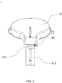
FIG. 2 is a rear view of the explosion-proof lamp shown inFIG. 1 ; -
FIG. 3 is a front view of the explosion-proof lamp shown inFIG. 1 ; -
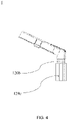
FIG. 4 is a side view of the explosion-proof lamp shown inFIG. 1 ; -
FIG. 5 is a perspective exploded view of the explosion-proof lamp shown inFIG. 1 ; -
FIG. 6 is a perspective view of a cable entry assembly for the explosion-proof lamp shown inFIG. 1 ; and -
FIG. 7 is a cross-sectional view of a cable entry assembly for the explosion-proof lamp shown inFIG. 1 . - 1 - explosion-proof lamp; 10 - cover; 100 - extension portion; 100a - third positioning hole; 12 - cable entry assembly; 120 - first connecting member; 122 - positioning member; 122a - connecting portion; 122b - locking portion; 124 - second connecting member; 120a - gripping portion; 120b - flat surface; 124a - first positioning hole; 124b - second positioning hole; 124c - fastener
- Exemplary schemes of an explosion-proof lamp according to the present invention will be described in detail with reference to the accompanying drawings. Although providing the accompanying drawings is to present a plurality of implementations of the present invention, the accompanying drawings do not need to be drawn according to the size of specific implementation schemes, and certain features can be enlarged, removed, or locally exploded to better illustrate and explain the disclosure of the present invention. Part of members in the accompanying drawings can be positionally adjusted according to actual requirements without affecting the technical effect. In the description, the term "in the accompanying drawings" or similar terms do not necessarily refer to all of the accompanying drawings or examples.
- Certain directional terms used in the following to describe the accompanying drawings, such as "in," "out," "upper," and "lower," and other directional terms are construed as having normal meanings thereof and refer to those directions involved when the accompanying drawings are viewed normally. Unless otherwise specified, the directional terms in the description are substantially in accord with conventional directions understood by those skilled in the art.
- The terms "first," "first one," "second," and "second one" and similar terms used in the present invention do not indicate any sequence, number, or importance in the present invention, but are used to distinguish one component from other components.
- The terms "join" and "connect" and similar terms used in the present invention refer to two components being indirectly connected to each other by an intermediate layer (such as an adhesive or a solder) or an intermediate member (such as a connection member or a transition member), and also refer to two components being directly connected to each other without any intermediate layer (such as an adhesive or a solder) or any intermediate member (such as a connection member or a transition member).
-
FIG. 1 to FIG. 7 show a column-typecable entry assembly 12 for an explosion-proof lamp provided by the present invention. Specifically, as shown inFIG. 1 , the explosion-proof lamp 1 includes acover 10, acable entry assembly 12, and a rod. Thecover 10 is mainly used to arrange or mount a lamp body. Thecable entry assembly 12 is (detachably) joined to thecover 10. Thecable entry assembly 12 leads a cable to the interior thereof so as to guide and protect the cable. The cable is always connected to thecover 10. The rod is connected to thecover 10 by being (detachably) joined to thecable entry assembly 12. The rod is used to support the cover 10 (especially after the lamp body is arranged or mounted) so as to support thecover 10 to a certain height to meet lighting requirements of a use scenario. - As shown in
FIGs. 2 to 5 , thecable entry assembly 12 includes a first connectingmember 120, a second connectingmember 124, and apositioning member 122. Taking a direction in which the rod is upright as a reference, in an axial direction of the rod, an upper end of the first connectingmember 120 is joined to thecover 10. Thecover 10 is substantially a circular structure, and a connecting portion extends radially from thecover 10. The connecting portion is usually bent by a certain angle. A side of the bent connecting portion facing the rod is used to connect the first connectingmember 120. A lower end of the first connectingmember 120 is connected to (an upper end of) thepositioning member 122. After thepositioning member 122 is joined to the first connectingmember 120, the first connectingmember 120 is then joined to thecover 10. During the joining of the first connectingmember 120 to the cover, thepositioning member 122 does not lock the cable, and after the two are joined to each other, thepositioning member 122 locks and positions the cable. In this period, rotation caused by the joining of thepositioning member 122 to the first connectingmember 120 and the joining of the first connectingmember 120 to thecover 10 does not cause the cable to rotate, and this prevents the cable from becoming entangled during assembly of the explosion-proof lamp. An upper end of the second connectingmember 124 is connected to the lower end of the first connectingmember 120 so as to cause thepositioning member 122 to be sleeved therein and expose the first connectingmember 120, and this facilitates use of a tool to rotate the first connecting member. - The
positioning member 122 used herein is optionally a cable gland, especially an explosion-proof cable gland. The cable gland is applicable to hazardous environments, and meets explosion-proof certification requirements. The cable gland is an explosion-proof accessory applicable to a demanding cable. The cable gland can fix the position of and seal the cable, has superior flameproof performance and a safe and reliable structure, and facilitates mounting. Thepositioning member 122 includes a connectingportion 122a, a sealing portion, and alocking portion 122b. The connectingportion 122a is joined to the first connecting member. The sealing portion abuts to the connectingportion 122a. The lockingportion 122b usually achieves locking by acting on the sealing portion. For example, when the lockingportion 122b performs locking, the sealing portion deforms to fix the cable and seal the same, and when the lockingportion 122b does not perform locking, the sealing portion restores the shape and releases the cable so that the cable can move axially relative to the positioning member. - The first connecting
member 120, the positioningmember 122, and the second connectingmember 124 are all threadedly connected to each other. The first connectingmember 120 is configured to be column-shaped, and optionally the upper end and the lower end thereof form a tapered structure. The first connectingmember 120 is internally hollow so as to accommodate thepositioning member 122, allow the cable to pass therethrough, and guide the cable. Similar to the first connectingmember 120, the second connectingmember 124 is also configured to be a hollow column-type structure. After being connected to the first connectingmember 120, the second connectingmember 124 can accommodate a lower portion of the first connectingmember 120. - Exemplarily, in order to further fix and limit respective positions of the first connecting
member 120, the second connectingmember 124, and thecover 10 so as to prevent axial movement and radial rotation from occurring therebetween, the second connectingmember 124 is further provided with positioning holes on a peripheral surface. The positioning holes mainly include afirst positioning hole 124a located at the upper end of the second connectingmember 124 and asecond positioning hole 124b located at a lower end of the second connectingmember 124. Thefirst positioning hole 124a at the upper end of the second connectingmember 124 is used to limit relative rotation and axial movement between the second connectingmember 124 and the first connectingmember 120. Thesecond positioning hole 124b at the lower end of the second connectingmember 124 is used to limit relative rotation and axial movement between the second connectingmember 124 and the rod. The numbers offirst positioning holes 124a and second positioning holes 124b are respectively plural, for example, three as shown inFIG. 5 . However, those skilled in the art can understand that the number of positioning holes can be adjusted according to actual requirements. Fixing of the second connectingmember 124 to the first connectingmember 120 is achieved by causing a fastener to pass through thefirst positioning hole 124a and abut to the first connectingmember 120, and fixing of the second connectingmember 124 to the rod is achieved by causing a fastener to pass through thesecond positioning hole 124b and abut to the rod. - Exemplarily, the
first positioning hole 124a and thesecond positioning hole 124b may be arranged with reference to the following manner. TakingFIG. 6 as an example, threefirst positioning holes 124a and three second positioning holes 124b are respectively circumferentially evenly distributed on the peripheral surface of the second connectingmember 124. That is, a plurality offirst positioning holes 124a are circumferentially co-circularly arranged, and similarly, a plurality of second positioning holes 124b are also circumferentially co-circularly arranged. In addition, thefirst positioning hole 124a and thesecond positioning hole 124b are coaxially arranged on the second connectingmember 124, and vertically correspond to each other. Certainly, those skilled in the art can understand that the above arrangement is merely exemplary, and can also conceive of other possible arrangements. - In addition to the aforementioned further position-limiting and fixing between the two connecting members, the present invention further provides position-limiting and fixing between the
cover 10 and the first connectingmember 120. Specifically, thecover 10 has an extension portion protruding from a main body thereof towards a lower end. The extension portion is provided with athird positioning hole 124c. Similar to the connection between the aforementioned two connecting members, thecover 10 and the first connectingmember 120 are fixed to each other by causing a fastener to pass through thethird positioning hole 124c and abut to the first connectingmember 120. Advantageously, this prevents axial movement and radial rotation that may occur between thecover 10 and the first connectingmember 120. - The aforementioned fixing of the first connecting
member 120 to the second connectingmember 124 is described in detailed below. Specifically, the connection between the first connectingmember 120 and the second connectingmember 124 is fixed by using the aforementioned anti-rotation position-limiting method. That is, after the second connectingmember 124 is threadedly connected to the first connectingmember 120, anti-rotation position-limiting of the two is achieved by causing the fastener configured to be a locking screw to pass through thefirst positioning hole 124a at the upper end of the second connectingmember 124 and causing the locking screw to tightly abut to the first connectingmember 120. - The aforementioned fixing of the rod to the second connecting
member 124 is described in detailed below. Specifically, the rod is usually relatively long in order to easily support the explosion-proof lamp 1 to a relatively high position so as to meet lighting requirements. The rod is inserted into a relatively deep position of the second connectingmember 124 from the lower end of the second connectingmember 124. After the rod is inserted into an appropriate position in the second connectingmember 124, thefastener 124c (as shown inFIG. 4 ) is inserted into thesecond positioning hole 124b and is caused to abut to the peripheral surface of the second connectingmember 124 so as to limit or prevent relative rotation between the rod and the second connectingmember 124. Thepositioning hole 124a is usually a through-hole perpendicular to the peripheral surface of the second connectingmember 124. Certainly, it is understandable that those skilled in the art can adaptively adjust the number, the positions, and the arrangement ofpositioning holes 124a according to experience. However, these adjustments are all obtained on the basis of the teaching provided by the present invention, and do not depart from the protection scope of the present invention. - As an example, the first connecting
member 120 is provided with a first thread (for example, an external thread) and a second thread (for example, an internal thread) respectively at two ends on the peripheral surface, and is internally provided with a third thread (for example, an internal thread) at the lower end (namely, an end facing the cable gland). The connecting portion of thecover 10 is provided with a coupling thread on an end portion facing the first connectingmember 120 so as to be threadedly coupled to the first connectingmember 120. The positioning member 122 (cable gland) is threadedly connected, by means of a coupling thread provided on an upper end portion, to the third thread provided at the lower end of the first connectingmember 120. The second connecting member 124 (also referred to as a rod adapter) is provided with a coupling thread on an upper end portion so as to be threadedly connected to the second thread at the lower end of the first connectingmember 120. In the interior of the second connectingmember 124, except for the second internal thread provided on the upper portion, the other portion may be an unthreaded hole. After the connection between the second connectingmember 124 and the first connectingmember 120 is completed, the second connectingmember 124 causes thepositioning member 122 and part of the first connectingmember 120 to be sleeved therein. Since the connections between the first connectingmember 120, the positioningmember 122, and the second connectingmember 124 are appropriately designed, during mounting of the aforementioned components, the cable does not need to be rotated, thereby effectively avoiding the problem in which a cable becomes entangled during rotation due to that the cable is overly long. The aforementioned thread may be, for example, an NPT 1½thread (an American-standard 60-degree taper pipe thread), and has good sealing performance. - After being assembled to the cover and the rod, the aforementioned cable entry assembly can effectively prevent external gas, dust, etc. from entering the structure and affecting use performance and safety performance thereof. Sealing performed by the positioning member, namely the cable gland (mainly referring to the explosion-proof cable gland), on the cable can enable the structure provided herein to be applicable to hazardous explosive environments, for example, to be applicable to the petrochemical industry. Generally, depending on states of matter present in locations, hazardous locations are mainly divided into explosive gas environments and combustible dust environments. Depending on duration of hazardous matter in a location, a hazardous location including matter in two different states is divided into three regions. Taking the explosive gas environment as an example, depending on the frequency and duration of existence of an explosive gas mixture, the explosive gas environment is divided into three regions in China. These three regions are respectively region 0,
region 1, and region 2, and hazard levels thereof are in a descending order. The explosion-proof cable gland described herein is applicable toregion 1. - As shown in
FIG. 3 , the first connectingmember 120 is provided with a grippingportion 120a on a peripheral surface thereof. The grippingportion 120a is mainly used to allow an operator to readily use a tool to grip the same so as to complete coupling and mounting of the explosion-proof lamp. Generally, during a mounting or removal process, the operator uses a tool such as a wrench to grip the grippingportion 120a of the first connectingmember 120 so as to rotate the same. - In an embodiment, the gripping
portion 120a may be an annular flange arranged on the peripheral surface of the first connectingmember 120. The annular flange substantially surrounds the first connectingmember 120, and is formed by extending radially outwards from a surface of the first connectingmember 120. A surface of the flange is formed by a plurality offlat surfaces 120b, and the plurality offlat surfaces 120b are in pairs. For example, taking a diameter of the flange as a reference, one pair offlat surfaces 120b are distributed at two ends of the diameter of the flange on a peripheral surface of the flange. That is, at least one pair offlat surfaces 120b corresponding to each other on the flange is present on the peripheral surface of the flange, so that the operator can readily use a tool such as a wrench to grip the flange so as to rotate the same. - In another embodiment, the gripping
portion 120a may be at least one pair of flanges arranged on the peripheral surface of the first connectingmember 120. For example, the flange does not form any continuous annular structure, but extends radially from the surface of the first connectingmember 120 to form a boss. The surface of the flange, especially a surface located away from the peripheral surface of the first connectingmember 120, forms aflat surface 120b. Flanges in each of one or more pairs of flanges on the first connectingmember 120 are both arranged along the same diameter of the first connectingmember 120, and respectiveflat surfaces 120b of respective surfaces of the paired flanges are parallel to each other, so that the operator can readily use a tool such as a wrench to grip the flange so as to rotate the same. - In yet another embodiment, referring again to
FIGs. 3 and4 , the grippingportion 120a may be at least one pair offlat surfaces 120b directly arranged on the peripheral surface of the first connectingmember 120. Similar to the arrangement of the flange, theflat surfaces 120b directly arranged on the peripheral surface of the first connectingmember 120 also correspond to each other and are parallel to each other. As described above, the advantage of such arrangement is that the operator can readily use a tool such as a wrench to grip the flat surface so as to rotate the first connectingmember 120, so that the first connectingmember 120 is connected to or disengages from other structures, such as thecover 10. - Preferably, the aforementioned column-type second connecting
member 124 may be a polygonal column-type structure. In other words, the surface of the second connectingmember 124 may include at least one pair offlat surfaces 120b. As shown inFIGs. 4 and6 ,flat surfaces 120b of the at least one pair offlat surfaces 120b are opposite each other, that is, theflat surfaces 120b of the at least one pair offlat surfaces 120b are arranged at two ends of the diameter of the second connectingmember 124 and are parallel to each other. The objective of such configuration is also similar to the objective of providing the grippingportion 120a on the first connectingmember 120 described above, and such configuration allows the operator to readily rotate the second connectingmember 124. Similar to the first connectingmember 120, the second connectingmember 124 may also be optionally provided with a flange or another protruding grippingportion 120a. However, such configuration will be appropriately adjusted according to ease of operation and machining costs. Certainly, those skilled in the art can expect other possible alternatives after learning the technical solution of the present application. However, none of modifications or substitutions made thereto departs from the protection scope of the present invention. - Regarding the mounting process of the explosion-
proof lamp 1 provided herein, for ease of description and in order to highlight key points, only mounting of thecable entry assembly 12 to thecover 10 and the rod is described herein; other possible mounting steps involved in this process may be implemented with reference to the prior art or are steps known to those skilled in the art, and are therefore not repeatedly described herein. - At a mounting site, components to be mounted are prepared, and mainly include the
cover 10, the first connectingmember 120, the positioningmember 122, the cable, the second connectingmember 124, and the rod. The positioningmember 122, namely the explosion-proof cable gland, meets explosion-proof standards for the use environment, and acquires relevant explosion-proof certification. The explosion-proof cable gland is used to fasten and seal the cable. The fastening is mainly implemented by locking the cable by means of the cable gland so that the cable does not move axially, and does not rotate radially, thereby ensuring that the connection of the cable is normal. The sealing is mainly implemented in that dust, moisture, etc. are isolated and blocked in the use environment so as to protect the cable. The explosion-proof cable gland described herein is widely applicable to the petroleum industry, the chemical industry, and other locations requiring electrical safety and explosion proofing. - After the cable gland is sleeved on the cable and when the cable is not locked, the connecting
portion 122a of the cable gland is connected to the first connectingmember 120. During this period, the cable passes through the first connectingmember 120, and the cable gland is coupled and connected, by means of a coupling thread provided at an upper end thereof, to the third thread provided at the lower end of the first connectingmember 120 so that the two are fixed to each other. - Then, the first connecting
member 120 is connected to thecover 10, and thecover 10 is coupled and connected, by means of a coupling thread thereof, to the first thread provided at the upper end of the first connectingmember 120 so that the two are fixed to each other. Thethird positioning hole 100a on theextension portion 100 at the lower end of thecover 10 is coupled to thefastener 124c, and thefastener 124c abuts to the first connectingmember 120, so that respective positions of thecover 10 and the first connectingmember 120 are limited. Then, the lockingportion 122b of the cable gland is caused to act on the sealing portion so as to lock the cable; then, the second connectingmember 124 is connected to the first connectingmember 120, and the second connectingmember 124 is coupled and connected, by means of the coupling thread provided at the upper end thereof, to the second thread provided at the lower end of the first connectingmember 120, so that the two are fixed to each other. In addition, thefirst positioning hole 124a provided on the peripheral surface at the upper end of the second connectingmember 124 is coupled to thefastener 124c, and thefastener 124c abuts to the first connectingmember 124a, so that respective positions of the two connecting members are limited. Those skilled in the art can conceive that the aforementioned threaded connection is achieved by means of connection between an internal thread and an external thread of two components. Certainly, the internal thread and the external thread may be interchangeable, and this can be adaptively adjusted in consideration of machining costs and ease of operation. - Then, the rod is inserted into the second connecting
member 124, and after the rod reaches a pre-configured position in the second connecting member 124 (after mounting is completed, the rod supports a position at a required height on the lamp), thefastener 124c is aligned with and inserted into thesecond positioning hole 124b provided on the second connectingmember 124, so that thefastener 124c tightly abuts to the rod. The coupling between thefastener 124c and the positioning hole achieves anti-rotation position-limiting between components connected to each other, and prevents axial movement and radial rotation between the components connected to each other. - During the aforementioned mounting process, the positioning
member 122 locks the cable only after the first connectingmember 120 is connected to thecover 10 so as to prevent the cable from being entangled in preceding mounting steps, thereby improving on-site assembly efficiency and ease of operation. - After using the column-type cable entry assembly provided herein to complete the assembly of the explosion-proof lamp, the inventor conducted performance tests on the assembled explosion-proof lamp, the tests including dustproofing and waterproofing performance tests. A test result indicates that no dust or moisture can enter or permeate into the aforementioned explosion-proof lamp, and therefore the explosion-proof lamp has excellent dustproofing and waterproofing performance.
- The column-type assembly provided herein connects the rod and the cover. In addition, the appropriate design of the column-type assembly simplifies mounting steps of the explosion-proof lamp, and avoids the problem in the existing design in which a cable is prone to entanglement during assembly and connection of various components, thereby effectively improving assembly efficiency, and improving user experience. However, those skilled in the art can expect that the column-type assembly provided by the present invention is applicable to the explosion-proof lamp, and is also applicable to any other vertical lamp. If the column-type assembly is applied to another vertical lamp, then those skilled in the art can adjust and replace, according to experience, components involved therein. For example, it is not necessary to use an explosion-proof cable gland, and a cable gland applicable to a corresponding environment is selected, and so on.
- The column-type cable entry assembly provided by the present invention has an appropriate structure and arrangement, and therefore does not need a plurality of additional components for structural sealing, thereby reducing costs and simplifying mounting steps. In addition, during assembly, a cable no longer needs to rotate together with components attached thereto, thereby solving the technical problem in the prior art in which a long cable is prone to entanglement. Moreover, the column-type cable entry assembly also has good and stable waterproofing and dustproofing performance, improves assembly efficiency, and ensures the safety performance of a product. Further, after the first connecting member is connected to the cover, most of the main body is still exposed, so that a user can readily access and operate the same, thereby also reducing the difficulty of operation performed on the structure, and providing good experience to the user.
- Although the present invention is described in detail by using only a limited number of embodiments, it should be readily understood that the present invention is not limited to such disclosed embodiments. Instead, the present invention can be modified by incorporating any number of variations, alterations, substitutions, or equivalent devices not heretofore described, but these are commensurate with the spirit and the scope of the present invention. In addition, although various embodiments of the present invention have been described, it can be understood that aspects of the present invention may include only some of the embodiments. Therefore, the present invention is not to be construed as having been limited by the foregoing description, but is only limited by the appended claims.
Claims (10)
- A column-type cable entry assembly (12) for an explosion-proof lamp, the cable entry assembly (12) being used to connect a cover (10) and a rod of the explosion-proof lamp and to allow a cable for power transmission to pass therethrough, characterized by comprising:a first connecting member (120), the first connecting member (120) having one end joined to the cover (10);a positioning member (122), the positioning member (122) being joined to the first connecting member (120), not locking the cable during joining of the first connecting member (120) to the cover (10), and locking and positioning the cable after the first connecting member (120) is joined to the cover (10) so as to prevent the cable from rotating during joining of the positioning member (122) to the first connecting member (120) and during the joining of the first connecting member (120) to the cover (10), and an end of the positioning member (122) not joined to the first connecting member (120) exposing part of the first connecting member (120); anda second connecting member (124), the second connecting member (124) being connected to the other end of the first connecting member (120) so as to cause the positioning member (122) to be sleeved therein and expose the first connecting member (120).
- The column-type cable entry assembly (12) according to claim 1, wherein the positioning member (122) is configured to be an explosion-proof cable gland, and the positioning member (122) comprises:a connecting portion (122a), the connecting portion (122a) being configured to be joined to the first connecting member (120);
a sealing portion, the sealing portion abutting to the connecting portion (122a); anda locking portion (122b), the locking portion (122b) being configured to disengage from or lock the sealing portion so as to release or lock and position the cable. - The column-type cable entry assembly (12) according to claim 1, wherein the second connecting member (124) is configured to be column-shaped; the second connecting member (124) is provided with a first positioning hole (124a) and a second positioning hole (124b) on a peripheral surface thereof; the first positioning hole (124a) and the second positioning hole (124b) are respectively close to two ends of the second connecting member (124); the first connecting member (120) and the second connecting member (124) are fixed to each other by causing a fastener (124c) to pass through the first positioning hole (124a) and abut to the first connecting member (120); the rod is inserted into the second connecting member (124), and the rod and the second connecting member (124) are fixed to each other by causing a fastener (124c) to pass through the second positioning hole (124b) and abut to the rod, so as to prevent axial and radial displacement from occurring between the second connecting member (124) and the first connecting member (120) and between the second connecting member (124) and the rod.
- The column-type cable entry assembly (12) according to claim 3, wherein the first positioning hole (124a) and the second positioning hole (124b) are circumferentially and evenly arranged on the peripheral surface of the second connecting member (124).
- The column-type cable entry assembly (12) according to claim 3, wherein the first positioning hole (124a) and the second positioning hole (124b) are coaxially arranged on the peripheral surface of the second connecting member (124).
- The column-type cable entry assembly (12) according to claim 1, wherein the cover (10) has an extension portion (100) protruding from a main body thereof towards the second connecting member (124); the extension portion (100) is provided with a third positioning hole (100a); the first connecting member (120) and the cover (10) are fixed to each other by causing a fastener (124c) to pass through the third positioning hole (100a) and abut to the first connecting member (120) so as to prevent axial and radial displacement of the cover (10) relative to the first connecting member (120).
- The column-type cable entry assembly (12) according to claim 1, wherein one end of the first connecting member (120) is provided with a first thread so as to be threadedly coupled to the cover (10); the other end of the first connecting member (120) is provided with a second thread so as to be threadedly coupled to an end of the second connecting member (124); and the other end of the first connecting member (120) is further provided with a third thread so as to be threadedly coupled to the positioning member (122).
- The column-type cable entry assembly (12) according to claim 1, wherein the first connecting member (120) is configured to be provided with a gripping portion (120a) on a peripheral surface thereof so as to allow coupling and mounting of the explosion-proof lamp.
- The column-type cable entry assembly (12) according to claim 8, wherein the gripping portion (120a) is configured to be an annular flange arranged on the peripheral surface, and the flange has at least one pair of flat surfaces (120b) parallel to each other on the peripheral surface.
- The column-type cable entry assembly (12) according to claim 8, wherein the gripping portion (120a) is configured to be at least one pair of flat surfaces (120b) arranged on the peripheral surface, and the at least one pair of flat surfaces (120b) correspond to and are parallel each other.
Applications Claiming Priority (1)
| Application Number | Priority Date | Filing Date | Title |
|---|---|---|---|
| CN202011041332.6A CN114321763A (en) | 2020-09-28 | 2020-09-28 | A column inlet wire subassembly for explosion-proof lamps and lanterns |
Publications (2)
| Publication Number | Publication Date |
|---|---|
| EP3974717A1 true EP3974717A1 (en) | 2022-03-30 |
| EP3974717B1 EP3974717B1 (en) | 2024-12-18 |
Family
ID=78179161
Family Applications (1)
| Application Number | Title | Priority Date | Filing Date |
|---|---|---|---|
| EP21199641.8A Active EP3974717B1 (en) | 2020-09-28 | 2021-09-28 | Columnar wire-in assembly for explosion-proof lamp |
Country Status (3)
| Country | Link |
|---|---|
| EP (1) | EP3974717B1 (en) |
| KR (1) | KR20220043061A (en) |
| CN (1) | CN114321763A (en) |
Citations (2)
| Publication number | Priority date | Publication date | Assignee | Title |
|---|---|---|---|---|
| CN207378639U (en) * | 2017-11-14 | 2018-05-18 | 华荣科技股份有限公司 | Explosion-proof lamp component |
| CN209213609U (en) * | 2018-12-27 | 2019-08-06 | 荣朗防爆科技有限公司 | A kind of explosion suppression type explosion-preventing lamp |
Family Cites Families (7)
| Publication number | Priority date | Publication date | Assignee | Title |
|---|---|---|---|---|
| KR920003103Y1 (en) * | 1989-09-19 | 1992-05-21 | 주식회사 협신기업 | Prefabricated backrest of cast iron back |
| CN202696080U (en) * | 2012-08-15 | 2013-01-23 | 李德胜 | Stainless-steel anti-explosion seal gland |
| KR101533314B1 (en) * | 2013-05-21 | 2015-07-03 | 에스케이씨라이팅 주식회사 | Light emitting diode explosion-proof light |
| US20170233995A1 (en) * | 2016-02-16 | 2017-08-17 | Bull Moose Tube Company | Connectors and methods of assembling the same |
| CN206640286U (en) * | 2017-03-09 | 2017-11-14 | 上海发电设备成套设计研究院 | A kind of nuclear power generating equipment qualification test cable gland head |
| CN206530921U (en) * | 2017-03-09 | 2017-09-29 | 禾财记兴业有限公司 | Floor lamp and assembled support unit thereof |
| CN209458725U (en) * | 2018-12-25 | 2019-10-01 | 弗朗电气有限公司 | Explosion-proof platform lamp |
-
2020
- 2020-09-28 CN CN202011041332.6A patent/CN114321763A/en active Pending
-
2021
- 2021-09-28 EP EP21199641.8A patent/EP3974717B1/en active Active
- 2021-09-28 KR KR1020210128379A patent/KR20220043061A/en active Pending
Patent Citations (2)
| Publication number | Priority date | Publication date | Assignee | Title |
|---|---|---|---|---|
| CN207378639U (en) * | 2017-11-14 | 2018-05-18 | 华荣科技股份有限公司 | Explosion-proof lamp component |
| CN209213609U (en) * | 2018-12-27 | 2019-08-06 | 荣朗防爆科技有限公司 | A kind of explosion suppression type explosion-preventing lamp |
Also Published As
| Publication number | Publication date |
|---|---|
| EP3974717B1 (en) | 2024-12-18 |
| KR20220043061A (en) | 2022-04-05 |
| CN114321763A (en) | 2022-04-12 |
Similar Documents
| Publication | Publication Date | Title |
|---|---|---|
| CN105722764B (en) | Fastener for explosion-proof case | |
| CN1230960C (en) | Connection accessories and connection methods | |
| JP6531628B2 (en) | Case closing structure | |
| JP6131997B2 (en) | Seal cover | |
| EP3974717B1 (en) | Columnar wire-in assembly for explosion-proof lamp | |
| CN118676694B (en) | Irradiation-resistant direct push-pull self-locking sealing connector | |
| CN215061673U (en) | LED explosion-proof lamp | |
| JP2023116102A (en) | Terminal block for motor | |
| US20140326498A1 (en) | Universal bushing | |
| KR101844983B1 (en) | Cable supporting module and Construction method using the same | |
| CN119163635A (en) | ceiling fan | |
| JP2020107474A (en) | Fall prevention tool, installation structure of equipment, and fall prevention method of equipment | |
| JPWO2018011910A1 (en) | Rotor mounting structure and centrifuge | |
| US11435540B2 (en) | Cable management system for a splice enclosure, and a splice enclosure with a cable management system | |
| JP2016046933A (en) | Wiring box | |
| KR102817759B1 (en) | Pressurized Explosion-Proof Cable Gland | |
| CN111146745B (en) | Cable split-type assembled external support for transistor | |
| CA2893227C (en) | Field serviceable conduit receivers | |
| EP4023399A1 (en) | Connection assembly for robot joints | |
| US20240329350A1 (en) | Transition for optical fibre cable | |
| US12467611B1 (en) | Ceiling fan lamp quick assembly structure | |
| JP6452499B2 (en) | Buried gas plug | |
| KR102252152B1 (en) | Rotation angle adjustment device using pitch subdivision of radial clutch | |
| US12376249B2 (en) | Electronic device and gasket | |
| KR102791618B1 (en) | Automatic alignment assembly device for anti-vibration structures |
Legal Events
| Date | Code | Title | Description |
|---|---|---|---|
| PUAI | Public reference made under article 153(3) epc to a published international application that has entered the european phase |
Free format text: ORIGINAL CODE: 0009012 |
|
| STAA | Information on the status of an ep patent application or granted ep patent |
Free format text: STATUS: REQUEST FOR EXAMINATION WAS MADE |
|
| 17P | Request for examination filed |
Effective date: 20210928 |
|
| AK | Designated contracting states |
Kind code of ref document: A1 Designated state(s): AL AT BE BG CH CY CZ DE DK EE ES FI FR GB GR HR HU IE IS IT LI LT LU LV MC MK MT NL NO PL PT RO RS SE SI SK SM TR |
|
| STAA | Information on the status of an ep patent application or granted ep patent |
Free format text: STATUS: EXAMINATION IS IN PROGRESS |
|
| 17Q | First examination report despatched |
Effective date: 20220915 |
|
| P01 | Opt-out of the competence of the unified patent court (upc) registered |
Effective date: 20230521 |
|
| GRAP | Despatch of communication of intention to grant a patent |
Free format text: ORIGINAL CODE: EPIDOSNIGR1 |
|
| STAA | Information on the status of an ep patent application or granted ep patent |
Free format text: STATUS: GRANT OF PATENT IS INTENDED |
|
| INTG | Intention to grant announced |
Effective date: 20240717 |
|
| GRAS | Grant fee paid |
Free format text: ORIGINAL CODE: EPIDOSNIGR3 |
|
| GRAA | (expected) grant |
Free format text: ORIGINAL CODE: 0009210 |
|
| STAA | Information on the status of an ep patent application or granted ep patent |
Free format text: STATUS: THE PATENT HAS BEEN GRANTED |
|
| AK | Designated contracting states |
Kind code of ref document: B1 Designated state(s): AL AT BE BG CH CY CZ DE DK EE ES FI FR GB GR HR HU IE IS IT LI LT LU LV MC MK MT NL NO PL PT RO RS SE SI SK SM TR |
|
| REG | Reference to a national code |
Ref country code: CH Ref legal event code: EP |
|
| REG | Reference to a national code |
Ref country code: DE Ref legal event code: R096 Ref document number: 602021023486 Country of ref document: DE |
|
| REG | Reference to a national code |
Ref country code: IE Ref legal event code: FG4D |
|
| REG | Reference to a national code |
Ref country code: LT Ref legal event code: MG9D |
|
| PG25 | Lapsed in a contracting state [announced via postgrant information from national office to epo] |
Ref country code: HR Free format text: LAPSE BECAUSE OF FAILURE TO SUBMIT A TRANSLATION OF THE DESCRIPTION OR TO PAY THE FEE WITHIN THE PRESCRIBED TIME-LIMIT Effective date: 20241218 |
|
| PG25 | Lapsed in a contracting state [announced via postgrant information from national office to epo] |
Ref country code: FI Free format text: LAPSE BECAUSE OF FAILURE TO SUBMIT A TRANSLATION OF THE DESCRIPTION OR TO PAY THE FEE WITHIN THE PRESCRIBED TIME-LIMIT Effective date: 20241218 |
|
| PG25 | Lapsed in a contracting state [announced via postgrant information from national office to epo] |
Ref country code: BG Free format text: LAPSE BECAUSE OF FAILURE TO SUBMIT A TRANSLATION OF THE DESCRIPTION OR TO PAY THE FEE WITHIN THE PRESCRIBED TIME-LIMIT Effective date: 20241218 |
|
| REG | Reference to a national code |
Ref country code: NL Ref legal event code: MP Effective date: 20241218 |
|
| PG25 | Lapsed in a contracting state [announced via postgrant information from national office to epo] |
Ref country code: LV Free format text: LAPSE BECAUSE OF FAILURE TO SUBMIT A TRANSLATION OF THE DESCRIPTION OR TO PAY THE FEE WITHIN THE PRESCRIBED TIME-LIMIT Effective date: 20241218 Ref country code: GR Free format text: LAPSE BECAUSE OF FAILURE TO SUBMIT A TRANSLATION OF THE DESCRIPTION OR TO PAY THE FEE WITHIN THE PRESCRIBED TIME-LIMIT Effective date: 20250319 |
|
| PG25 | Lapsed in a contracting state [announced via postgrant information from national office to epo] |
Ref country code: RS Free format text: LAPSE BECAUSE OF FAILURE TO SUBMIT A TRANSLATION OF THE DESCRIPTION OR TO PAY THE FEE WITHIN THE PRESCRIBED TIME-LIMIT Effective date: 20250318 |
|
| PG25 | Lapsed in a contracting state [announced via postgrant information from national office to epo] |
Ref country code: NL Free format text: LAPSE BECAUSE OF FAILURE TO SUBMIT A TRANSLATION OF THE DESCRIPTION OR TO PAY THE FEE WITHIN THE PRESCRIBED TIME-LIMIT Effective date: 20241218 |
|
| REG | Reference to a national code |
Ref country code: AT Ref legal event code: MK05 Ref document number: 1752491 Country of ref document: AT Kind code of ref document: T Effective date: 20241218 |
|
| PG25 | Lapsed in a contracting state [announced via postgrant information from national office to epo] |
Ref country code: SM Free format text: LAPSE BECAUSE OF FAILURE TO SUBMIT A TRANSLATION OF THE DESCRIPTION OR TO PAY THE FEE WITHIN THE PRESCRIBED TIME-LIMIT Effective date: 20241218 |
|
| PG25 | Lapsed in a contracting state [announced via postgrant information from national office to epo] |
Ref country code: PL Free format text: LAPSE BECAUSE OF FAILURE TO SUBMIT A TRANSLATION OF THE DESCRIPTION OR TO PAY THE FEE WITHIN THE PRESCRIBED TIME-LIMIT Effective date: 20241218 |
|
| PG25 | Lapsed in a contracting state [announced via postgrant information from national office to epo] |
Ref country code: ES Free format text: LAPSE BECAUSE OF FAILURE TO SUBMIT A TRANSLATION OF THE DESCRIPTION OR TO PAY THE FEE WITHIN THE PRESCRIBED TIME-LIMIT Effective date: 20241218 |
|
| PG25 | Lapsed in a contracting state [announced via postgrant information from national office to epo] |
Ref country code: IS Free format text: LAPSE BECAUSE OF FAILURE TO SUBMIT A TRANSLATION OF THE DESCRIPTION OR TO PAY THE FEE WITHIN THE PRESCRIBED TIME-LIMIT Effective date: 20250418 |
|
| PG25 | Lapsed in a contracting state [announced via postgrant information from national office to epo] |
Ref country code: PT Free format text: LAPSE BECAUSE OF FAILURE TO SUBMIT A TRANSLATION OF THE DESCRIPTION OR TO PAY THE FEE WITHIN THE PRESCRIBED TIME-LIMIT Effective date: 20250421 |
|
| PG25 | Lapsed in a contracting state [announced via postgrant information from national office to epo] |
Ref country code: EE Free format text: LAPSE BECAUSE OF FAILURE TO SUBMIT A TRANSLATION OF THE DESCRIPTION OR TO PAY THE FEE WITHIN THE PRESCRIBED TIME-LIMIT Effective date: 20241218 |
|
| PG25 | Lapsed in a contracting state [announced via postgrant information from national office to epo] |
Ref country code: AT Free format text: LAPSE BECAUSE OF FAILURE TO SUBMIT A TRANSLATION OF THE DESCRIPTION OR TO PAY THE FEE WITHIN THE PRESCRIBED TIME-LIMIT Effective date: 20241218 Ref country code: RO Free format text: LAPSE BECAUSE OF FAILURE TO SUBMIT A TRANSLATION OF THE DESCRIPTION OR TO PAY THE FEE WITHIN THE PRESCRIBED TIME-LIMIT Effective date: 20241218 |
|
| PG25 | Lapsed in a contracting state [announced via postgrant information from national office to epo] |
Ref country code: SK Free format text: LAPSE BECAUSE OF FAILURE TO SUBMIT A TRANSLATION OF THE DESCRIPTION OR TO PAY THE FEE WITHIN THE PRESCRIBED TIME-LIMIT Effective date: 20241218 |
|
| PG25 | Lapsed in a contracting state [announced via postgrant information from national office to epo] |
Ref country code: CZ Free format text: LAPSE BECAUSE OF FAILURE TO SUBMIT A TRANSLATION OF THE DESCRIPTION OR TO PAY THE FEE WITHIN THE PRESCRIBED TIME-LIMIT Effective date: 20241218 |
|
| PG25 | Lapsed in a contracting state [announced via postgrant information from national office to epo] |
Ref country code: IT Free format text: LAPSE BECAUSE OF FAILURE TO SUBMIT A TRANSLATION OF THE DESCRIPTION OR TO PAY THE FEE WITHIN THE PRESCRIBED TIME-LIMIT Effective date: 20241218 |
|
| PG25 | Lapsed in a contracting state [announced via postgrant information from national office to epo] |
Ref country code: SE Free format text: LAPSE BECAUSE OF FAILURE TO SUBMIT A TRANSLATION OF THE DESCRIPTION OR TO PAY THE FEE WITHIN THE PRESCRIBED TIME-LIMIT Effective date: 20241218 |
|
| REG | Reference to a national code |
Ref country code: DE Ref legal event code: R097 Ref document number: 602021023486 Country of ref document: DE |
|
| PG25 | Lapsed in a contracting state [announced via postgrant information from national office to epo] |
Ref country code: DK Free format text: LAPSE BECAUSE OF FAILURE TO SUBMIT A TRANSLATION OF THE DESCRIPTION OR TO PAY THE FEE WITHIN THE PRESCRIBED TIME-LIMIT Effective date: 20241218 |
|
| PGFP | Annual fee paid to national office [announced via postgrant information from national office to epo] |
Ref country code: DE Payment date: 20250820 Year of fee payment: 5 |
|
| PGFP | Annual fee paid to national office [announced via postgrant information from national office to epo] |
Ref country code: NO Payment date: 20250825 Year of fee payment: 5 |
|
| PGFP | Annual fee paid to national office [announced via postgrant information from national office to epo] |
Ref country code: GB Payment date: 20250822 Year of fee payment: 5 |
|
| PGFP | Annual fee paid to national office [announced via postgrant information from national office to epo] |
Ref country code: FR Payment date: 20250821 Year of fee payment: 5 |
|
| PLBE | No opposition filed within time limit |
Free format text: ORIGINAL CODE: 0009261 |
|
| STAA | Information on the status of an ep patent application or granted ep patent |
Free format text: STATUS: NO OPPOSITION FILED WITHIN TIME LIMIT |
|
| REG | Reference to a national code |
Ref country code: CH Ref legal event code: L10 Free format text: ST27 STATUS EVENT CODE: U-0-0-L10-L00 (AS PROVIDED BY THE NATIONAL OFFICE) Effective date: 20251029 |
|
| 26N | No opposition filed |
Effective date: 20250919 |
|
| REG | Reference to a national code |
Ref country code: CH Ref legal event code: H13 Free format text: ST27 STATUS EVENT CODE: U-0-0-H10-H13 (AS PROVIDED BY THE NATIONAL OFFICE) Effective date: 20260504 |