EP3974704A1 - Linear lamp - Google Patents
Linear lamp Download PDFInfo
- Publication number
- EP3974704A1 EP3974704A1 EP20868357.3A EP20868357A EP3974704A1 EP 3974704 A1 EP3974704 A1 EP 3974704A1 EP 20868357 A EP20868357 A EP 20868357A EP 3974704 A1 EP3974704 A1 EP 3974704A1
- Authority
- EP
- European Patent Office
- Prior art keywords
- snap
- side body
- linear lamp
- fit
- adjacent
- Prior art date
- Legal status (The legal status is an assumption and is not a legal conclusion. Google has not performed a legal analysis and makes no representation as to the accuracy of the status listed.)
- Pending
Links
Images




Classifications
-
- F—MECHANICAL ENGINEERING; LIGHTING; HEATING; WEAPONS; BLASTING
- F21—LIGHTING
- F21S—NON-PORTABLE LIGHTING DEVICES; SYSTEMS THEREOF; VEHICLE LIGHTING DEVICES SPECIALLY ADAPTED FOR VEHICLE EXTERIORS
- F21S4/00—Lighting devices or systems using a string or strip of light sources
- F21S4/20—Lighting devices or systems using a string or strip of light sources with light sources held by or within elongate supports
- F21S4/28—Lighting devices or systems using a string or strip of light sources with light sources held by or within elongate supports rigid, e.g. LED bars
-
- F—MECHANICAL ENGINEERING; LIGHTING; HEATING; WEAPONS; BLASTING
- F21—LIGHTING
- F21K—NON-ELECTRIC LIGHT SOURCES USING LUMINESCENCE; LIGHT SOURCES USING ELECTROCHEMILUMINESCENCE; LIGHT SOURCES USING CHARGES OF COMBUSTIBLE MATERIAL; LIGHT SOURCES USING SEMICONDUCTOR DEVICES AS LIGHT-GENERATING ELEMENTS; LIGHT SOURCES NOT OTHERWISE PROVIDED FOR
- F21K9/00—Light sources using semiconductor devices as light-generating elements, e.g. using light-emitting diodes [LED] or lasers
- F21K9/20—Light sources comprising attachment means
- F21K9/27—Retrofit light sources for lighting devices with two fittings for each light source, e.g. for substitution of fluorescent tubes
- F21K9/275—Details of bases or housings, i.e. the parts between the light-generating element and the end caps; Arrangement of components within bases or housings
-
- F—MECHANICAL ENGINEERING; LIGHTING; HEATING; WEAPONS; BLASTING
- F21—LIGHTING
- F21V—FUNCTIONAL FEATURES OR DETAILS OF LIGHTING DEVICES OR SYSTEMS THEREOF; STRUCTURAL COMBINATIONS OF LIGHTING DEVICES WITH OTHER ARTICLES, NOT OTHERWISE PROVIDED FOR
- F21V17/00—Fastening of component parts of lighting devices, e.g. shades, globes, refractors, reflectors, filters, screens, grids or protective cages
- F21V17/10—Fastening of component parts of lighting devices, e.g. shades, globes, refractors, reflectors, filters, screens, grids or protective cages characterised by specific fastening means or way of fastening
- F21V17/16—Fastening of component parts of lighting devices, e.g. shades, globes, refractors, reflectors, filters, screens, grids or protective cages characterised by specific fastening means or way of fastening by deformation of parts; Snap action mounting
-
- F—MECHANICAL ENGINEERING; LIGHTING; HEATING; WEAPONS; BLASTING
- F21—LIGHTING
- F21V—FUNCTIONAL FEATURES OR DETAILS OF LIGHTING DEVICES OR SYSTEMS THEREOF; STRUCTURAL COMBINATIONS OF LIGHTING DEVICES WITH OTHER ARTICLES, NOT OTHERWISE PROVIDED FOR
- F21V21/00—Supporting, suspending, or attaching arrangements for lighting devices; Hand grips
- F21V21/005—Supporting, suspending, or attaching arrangements for lighting devices; Hand grips for several lighting devices in an end-to-end arrangement, i.e. light tracks
-
- F—MECHANICAL ENGINEERING; LIGHTING; HEATING; WEAPONS; BLASTING
- F21—LIGHTING
- F21V—FUNCTIONAL FEATURES OR DETAILS OF LIGHTING DEVICES OR SYSTEMS THEREOF; STRUCTURAL COMBINATIONS OF LIGHTING DEVICES WITH OTHER ARTICLES, NOT OTHERWISE PROVIDED FOR
- F21V21/00—Supporting, suspending, or attaching arrangements for lighting devices; Hand grips
- F21V21/02—Wall, ceiling, or floor bases; Fixing pendants or arms to the bases
- F21V21/025—Elongated bases having a U-shaped cross section
-
- F—MECHANICAL ENGINEERING; LIGHTING; HEATING; WEAPONS; BLASTING
- F21—LIGHTING
- F21V—FUNCTIONAL FEATURES OR DETAILS OF LIGHTING DEVICES OR SYSTEMS THEREOF; STRUCTURAL COMBINATIONS OF LIGHTING DEVICES WITH OTHER ARTICLES, NOT OTHERWISE PROVIDED FOR
- F21V23/00—Arrangement of electric circuit elements in or on lighting devices
- F21V23/001—Arrangement of electric circuit elements in or on lighting devices the elements being electrical wires or cables
-
- F—MECHANICAL ENGINEERING; LIGHTING; HEATING; WEAPONS; BLASTING
- F21—LIGHTING
- F21V—FUNCTIONAL FEATURES OR DETAILS OF LIGHTING DEVICES OR SYSTEMS THEREOF; STRUCTURAL COMBINATIONS OF LIGHTING DEVICES WITH OTHER ARTICLES, NOT OTHERWISE PROVIDED FOR
- F21V23/00—Arrangement of electric circuit elements in or on lighting devices
- F21V23/06—Arrangement of electric circuit elements in or on lighting devices the elements being coupling devices, e.g. connectors
-
- F—MECHANICAL ENGINEERING; LIGHTING; HEATING; WEAPONS; BLASTING
- F21—LIGHTING
- F21Y—INDEXING SCHEME ASSOCIATED WITH SUBCLASSES F21K, F21L, F21S and F21V, RELATING TO THE FORM OR THE KIND OF THE LIGHT SOURCES OR OF THE COLOUR OF THE LIGHT EMITTED
- F21Y2103/00—Elongate light sources, e.g. fluorescent tubes
- F21Y2103/10—Elongate light sources, e.g. fluorescent tubes comprising a linear array of point-like light-generating elements
Definitions
- the present invention relates to the field of lighting technology, and in particular, to a linear lamp.
- the long-distance linear lamps are needed in places such as shopping malls and office buildings.
- the long-distance linear lamps are generally formed by splicing a plurality of linear lights.
- the linear light is formed by assembling a lamp shell, a photoelectric module disposed in the lamp shell, and a diffusion cover mounted at an open end of the lamp shell.
- the adjacent lamp shells are spliced together, the adjacent photoelectric modules are spliced together, and the adjacent diffusion covers are spliced together.
- Existing adjacent lamp shells are connected together by using a screw, and the splicing process is complicated.
- the present application proposes a linear lamp which is capable of improving the splicing convenience.
- the linear lamp comprises housings and a splicing member, the number of the housings is at least two, the splicing member is mounted at an end of each of the housings, and the two adjacent splicing members are in snap-fit connection to splice the two adjacent housings together.
- facing end faces of the two adjacent housings are attached to each other.
- the splicing member comprises a main body, a first side body, and a second side body, the first side body and the second side body are connected to and distributed on opposite sides of the main body, the first side body comprises a first snap-fit part, the second side body comprises a second snap-fit part, and the first snap-fit part of one splicing member and the second snap-fit part of the adjacent splicing member are in snap-fit connection.
- the first side body of one splicing member is limited in an outward direction by one of inner side walls of the housing
- the first side body of the adjacent splicing member is limited in an outward direction by another of the inner side walls of the housing
- the second side body is located on an inner side of the first side body and exerts outward extrusion force on the first side body.
- a slot is provided on the inner side wall, and the first side body is inserted in the slot.
- the splicing member further comprises a first connection body and a second connection body, the first connection body is connected to the main body and the first side body, the second connection body is connected to the main body and the second side body, and the first connection body is bent toward the inner side wall adjacent to the first connection body, and the second connection body is bent toward the inner side wall adjacent to the second connection body.
- the first snap-fit part protrudes out of an inner side surface of the first side body.
- the first side body comprises a through-hole (122) which is disposed adjacent to the first snap-fit part, and at least a portion of the second snap-fit part is located in the through-hole.
- the second snap-fit part protrudes out of an outer side surface of the second side body.
- the second snap-fit part extends from one end face of the second side body to another end of the second side body, and a groove is provided on the one end face of the second side body.
- a second guide part bent toward the first side body is provided on the another end.
- the first side body and the second side body both extend in a length direction of the housing, a length of the first side body is greater than a length of the second side body, the first snap-fit part of one of the housing extends into an inner cavity of the adjacent housing.
- the linear lamp further comprises a connector and at least two photoelectric modules, wherein the at least two photoelectric modules are mounted in the housing by using the connector, and the two adjacent photoelectric modules are electrically spliced together.
- each of the photoelectric modules comprises a light source plate, a light source disposed on an outer side surface of the light source plate, and a power supply located on an inner side of the light source plate, the connector encloses an accommodating cavity, and the light source plate, the light source, and the power supply are located in the accommodating cavity.
- the photoelectric module and the connectors are in snap-fit connection.
- the photoelectric module includes a snap-fit body, the connector comprises a hook, and the snap-fit body and the hook are in snap-fit connection.
- the connector comprises a side arm
- the side arm is an elastic arm being in snap-fit connection with the photoelectric module
- a movement gap for the side arm (32) to move is provided between the side arm and the housing
- the photoelectric module comprises an opening corresponding to the side arm
- the first side body or the second side body comprises an avoiding space
- the movement gap comprises the avoiding space
- the photoelectric module includes a plurality of groups of the light sources arranged at intervals in a length direction of the photoelectric module, and after the two adjacent photoelectric modules are spliced, distances between two adjacent groups of the light sources in any position are a same.
- the linear lamp further comprises a light distribution component, the light distribution component is an integrally formed member, and the adjacent housings are both connected to the light distribution component.
- the linear lamp of the present application has the advantage that: the two adjacent splicing members are in snap-fit connection and then the two adjacent housings are spliced together, and the two adjacent housings can be spliced quickly and conveniently.
- Splicing member 10 Main body 11; First side body 12; First snap-fit part 121; Guide slope 1211; First snap-fit surface 1212; Through-hole 122; Avoiding space 124; Reinforcing rib 125; Second side body 13; Second snap-fit part 131; Groove 1311; Second snap-fit surface 1312; Second guide part 132; Accommodating space 14; First connection body 15; Second connection body 16; Housing 20; First mounting space 21; Strip-shaped rib 22; Slot 23; Bottom plate 24; Side plate 25; snap-fit strip 26; Transition module 29; Connector 30; Accommodating cavity 31; Side arm 32; Bottom arm 33; Hook 321; Slope 3211; Photoelectric module 40; snap-fit body 41; Lining plate 42; Opening 421; Light source plate 43; Light source 431; Electrical connection terminal 44; Female head 441; Male head 442; Conversion terminal 45; Power supply 46; Light distribution component 50; Movement gap 60; and End cover 70.
- the embodiment discloses a linear lamp.
- the linear lamp includes a housing 20 and a splicing member 10, where the number of the housing 20 is at least two.
- Each of the splicing member 10 includes a main body 11, a first side body 12, and a second side body 13, wherein the first side body 12 and the second side body 13 are connected to and distributed on two opposite sides of the main body 11 respectively.
- a first snap-fit part 121 is provided in the first side body 12.
- a second snap-fit part 131 is provided in the second side body 13.
- the splicing member 10 has specific elasticity.
- the splicing member 10 may be a metal sheet.
- the main body 11, the first side body 12, and the second side body 13 may be integrally formed, or the main body 11, the first side body 12, and the second side body 13 may be welded and connected together.
- the first snap-fit part 121 of the first splicing member 10 and the second snap-fit part 131 of the second splicing member 10 are in snap-fit connection.
- the second snap-fit part 131 of the first splicing member 10 and the first snap-fit part 121 of the second splicing member 10 are in snap-fit connection. That is, the first snap-fit part 121 of one splicing member 10 and the second snap-fit part 131 of the adjacent splicing member 10 are in snap-fit connection. Therefore, the adjacent splicing members 10 are spliced together. After the splicing member 10 is mounted at an end of the housing 20, the adjacent splicing members 10 are spliced together, so that the two adjacent housings 20 are spliced together.
- the splicing member 10 is simple in structure and convenient to be spliced.
- the two splicing members 10 are opposite in placement direction and are connected to the adjacent housings 20 respectively, and then the two splicing members 10 are spliced, so that the two adjacent housings 20 can be rapidly spliced together.
- the splicing members 10 with a same structure are used, so that design cost can be reduced.
- the splicing members 10 are mounted at two ends of each housing 20 respectively.
- the housing 20 has two or more ends, and the splicing member 10 is mounted at each end.
- an end cover 70 is provided on an outer end of the housing 20 located on a tail portion of the linear lamp, and the splicing member 10 is mounted at an inner end.
- the housings 20 with different structures and the housings 20 in different positions are provided with different numbers of splicing members 10, which can be arranged according to actual needs.
- the housing 20 includes a bottom plate 24 and two side plates 25, wherein the bottom plate 24 and the two side plates 25 are connected and enclose a first mounting space 21.
- the splicing members 10 are entirely located in the first mounting space 21.
- the splicing members 10 can still be spliced together after being detached from the housing 20. Referring to FIG. 4 and FIG.
- the first side body 12 of one splicing member 10 is limited in an outward direction by an inner side wall of one side plate 25 of the housing 20, and the first side body 12 of the adjacent splicing member 10 is limited in an outward direction by an inner side wall of the other side plate 25 of the housing 20. Because the splicing members 10 have specific elasticity, the second side body 13 is located on an inner side of the first side body 12 and can exert outward extrusion force on the first side body 12.
- the side plate 25 has the function that when the second side body 13 outward extrudes the first side body 12, the side plate 25 can prevent the first side body 12 from moving outward, so that the second side body 13 is closely attached to the first side body 12, and the first snap-fit part 121 and the second snap-fit part 131 can be more reliably in snap-fit connection.
- the splicing members 10 have specific elasticity, so that the first snap-fit part 121 and the second snap-fit part 131 can more easily achieve snap-fit connection.
- the limiting effect of the side plate 25 prevents the first side body 12 from moving outward due to elasticity.
- the first side body 12, the second side body 13, and the main body 11 enclose an accommodating space 14.
- the splicing member 10 is inserted into the first mounting space 21, and the main body 11 is fixed to the bottom plate of the housing 20 by using a screw, so that the splicing member 10 is fixed in the housing 20, and the accommodating space 14 communicates with the first mounting space 21.
- the main body 11 is attached to the bottom plate 24 of the housing 20, and the first side body 12 and the second side body 13 are parallel to and closer to the two side plates 25 respectively, so that the splicing member 10 in the embodiment not only can rapidly connect the two adjacent housings 20, but also has the advantages of being small in occupied space and capable of accommodating other parts, for example, the accommodating space 14 may accommodate the photoelectric module 40.
- the splicing member 10 further includes a first connection body 15, one end of the first connection body 15 is connected to the main body 11, and the other end of the first connection body 15 is bent away from the second side body 13 toward the slot 23 and is connected to the first side body 12.
- the splicing member 10 further includes a second connection body 16, one end of the second connection body 16 is connected to the main body 11, and the other end of the second connection body 16 is bent away from the first side body 12 toward another slot 23 and is connected to the second side body 13.
- the first side body 12 can be inserted into the slot 23.
- the second side body 13 can be closer to the slot 23, or the second side body 13 is also inserted into the slot 23.
- the first side body 12 is limited in an outward direction by a slot bottom of the slot 23.
- the slot 23 can also limit the first side body 12 in an up and down direction and prevent the first side body 12 from dislocation, so that the first snap-fit part 121 and the second snap-fit part 131 are easily in snap-fit connection.
- the up and down direction herein is consistent with a width direction of the slot 23.
- the first side body 12 and the second side body 13 of the linear lamp both extend in the length direction of the housing 20, the length of the first side body 12 is larger, and the second side body 13 may be disposed directly facing the middle of the first side body 12.
- a left end of the first side body 12 and a right end of the second side body 13 are different-side ends, or a right end of the first side body 12 and a left end of the second side body 13 are different-side ends.
- the first snap-fit part 121 and the second snap-fit part 131 are distributed at the different-side ends of the first side body 12 and the second side body 13, so that the two splicing members 10 can have more overlapped parts when being spliced, and space can be saved.
- a through-hole 122 is provided on the first side body 12, the first snap-fit part 121 is disposed adjacent to the through-hole 122, and an edge of the first snap-fit part 121 forms a side wall of the through-hole 122.
- the first snap-fit part 121 is formed by partially recessing the first side body 12 toward the second side body 13, which is beneficial to reduce the number of components and parts.
- the first snap-fit part 121 protrudes out of an inner side surface of the first side body 12.
- the inner side surface of the first side body 12 is a surface facing toward the second side body 13.
- the through-hole 122 can accommodate a portion of the second snap-fit part 131, so that a contact area of the first snap-fit part 121 and the second snap-fit part 131 is relatively larger, which further improves reliability of the snap-fit connection of the first snap-fit part 121 and the second snap-fit part 131.
- a guide slope 1211 is provided on a surface of the first snap-fit part 121 facing toward the second side body 13, and the guide slope 1211 is used to improve splicing smoothness of the two splicing members 10.
- the second snap-fit part 131 is formed by partially recessing the second side body 13 away from the first side body 12, which is beneficial to reduce the number of components and parts.
- the second snap-fit part 131 protrudes out of an outer side surface of the second side body 13.
- the outer side surface of the second side body 13 is a surface facing away from the first side body 12.
- the second snap-fit part 131 extends from an end face of the second side body 13 to the other end of the second side body 13, a groove 1311 is provided on the second snap-fit part 131, and the groove 1311 extends from an end face of the second side body 13 to the other end of the second side body 13.
- a second guide part 132 bent toward the first side body 12 is provided at the other end of the second side body 13, thereby improving splicing smoothness of the two splicing members 10.
- surfaces of the snap-fit connection of the first snap-fit part 121 and the second snap-fit part 131 are a first snap-fit surface 1212 and a second snap-fit surface 1312 respectively, and the first snap-fit surface 1212 and the second snap-fit surface 1312 face each other and are in snap-fit connection.
- a tool is easily inserted into the groove 1311 and pries the first snap-fit part 121 and the second snap-fit part 131 so as to separate the first snap-fit part 121 and the second snap-fit part 131.
- a protruding height of the second snap-fit part 131 is less than a depth of the through-hole 122, that is, the depth of the through-hole 122 is larger, so that the second snap-fit part 131 cannot extend out of an outer surface of the first side body 12, the first side body 12 is attached to the slot bottom of the slot 23, occupied space is saved, and it can be ensured that the slot bottom of the slot 23 can limit the first side body 12.
- the outer surface of the first side body 12 is a surface of the first side body 12 facing away from the second side body 13.
- the slot bottom of the slot 23 is a side wall of the housing 20 located in the slot 23.
- first side body 12 has specific elasticity and a larger length
- a reinforcing rib 125 is provided on the first side body 12 and are used to increase insertion reliability of the first side body 12 and the slot 23.
- the reinforcing rib 125 may extend in the length direction of the first side body 12.
- FIG. 5 and FIG. 6 show two straight-line shape housings 20.
- the housing 20 includes a transition module 29, and the transition module 29 is used at a turn.
- the transition module 29 includes at least two extension parts 291, and the at least two extension parts 291 are perpendicular to each other.
- the number of the extension parts 291 is two, and the two extension parts 291 are perpendicular to form an L-shaped structure.
- the number of the extension parts 291 is three, two of the extension parts 291 are located on a same straight line, and the other one is perpendicular to the two extension parts 291 to form a T-shaped structure.
- the number of the extension parts 291 is four, and the four extension parts 291 are perpendicular to form a cross-shaped structure.
- the linear lamp further includes a connector 30 and a photoelectric module 40, where the number of the photoelectric module 40 is at least two, the photoelectric module 40 is mounted in the housing 20 by using the connector 30, and the two adjacent photoelectric modules 40 are electrically spliced together. As shown in FIG. 17 , only one photoelectric module 40 may be mounted in the first mounting space 21 of each housing 20. The photoelectric module 40 extends in the length direction of the housing 20.
- electrical connection terminals 44 are provided at two ends of the photoelectric module 40, and the electrical connection terminals 44 of the adjacent photoelectric modules 40 are electrically connected, so that the adjacent photoelectric modules 40 are connected together.
- the electrical connection terminals 44 at the two ends of each photoelectric module 40 may be different in structure, for example, may be a female head 441 and a male head 442 respectively.
- the female head 441 of one photoelectric module 40 and the male head 442 of the other photoelectric module 40 are in inserting connection cooperation.
- FIG. 20 and FIG. 21 when directions of the female head 441 and the male head 442 need to be changed, one conversion terminal 45 may be added.
- the female heads 441 may be arranged at two ends of the conversion terminal 45, or the male heads 442 may be arranged at two ends of the conversion terminal 45.
- the type of the conversion terminal 45 may be selected according to needs.
- the housing 20 has an open end opposite to the bottom plate 24.
- the connector 30 is inserted into the first mounting space 21 from the open end. As shown in FIG. 13 , the connector 30 has a bottom arm 33 and two side arms 32, the bottom arm 33 and the two side arms 32 are connected and enclose an accommodating cavity 31, the connector 30 has three open ends like the housing 20.
- the photoelectric module 40 is inserted into the accommodating cavity 31 from the open end of the connector 30 opposite to the bottom arm 33.
- the photoelectric module 40 may be partially or entirely located in the accommodating cavity 31.
- the bottom arm 33 of the connector 30 is fixed to the bottom plate 24 of the housing 20 by using a screw.
- the connector 30 is simple in structure and has a small occupied space.
- the photoelectric module 40 includes a light source plate 43, a light source 431 disposed on an outer side surface of the light source plate 43, and a power supply 46 located on an inner side of the light source plate 43, the connector 30 encloses an accommodating cavity 31, and the light source plate 43, the light source 431, and the power supply 46 are located in the accommodating cavity 31.
- the inner side of the light source plate 43 faces toward the bottom arm 33 and also faces toward the bottom plate 24.
- the photoelectric module 40 and the connector 30 are in snap-fit connection, so that the photoelectric module 40 is convenient to be mounted.
- the photoelectric module 40 comprises a snap-fit body 41, a hook 321 is formed on an inner side wall of the connector 30, and the snap-fit body 41 and the hook 321 are in snap-fit connection.
- the hook 321 comprises a slope 3211 for the photoelectric module 40 to be conveniently inserted into the accommodating cavity 31.
- the side arm 32 of the connector 30 is an elastic arm in snap-fit connection with the photoelectric module 40. As shown in FIG. 14 , a movement gap 60 is provided between the side arm 32 and the inner side wall of the housing 20, and the movement gap 60 is used for the side arm 32 to move.
- the photoelectric module 40 includes a lining plate 42 with an opening 421. At least a portion of the side arm 32 is disposed facing the opening 421, so that the side arm 32 can be pushed through the opening 421.
- the hook 321 is formed on an inner surface of the side arm 32.
- the adjacent housings 20 are spliced together first, and then the photoelectric module 40 is mounted in the first mounting space 21 of the housing 20.
- the photoelectric module 40 may be moved in a length direction of the photoelectric module 40 until the opening 421 is aligned with the side arm 32, so that the side arms 32 can be pushed through the opening 421.
- the lining plate 42 may be a reflector. As shown in FIG. 14 to FIG. 16 , the lining plates 42 are distributed on two sides of the light source plate 43 and configured to distribute light for the light source 431 on the light source plate 43, so that light emitting efficiency is improved.
- the reflector blocks the hook 321, the side arm 32 may be pressed through the opening 421, and the hook 321 may be separated from the snap-fit body 41, so that the photoelectric module 40 can be detached from the connector 30.
- the first side body 12 is longer, and the side arm 32 of the connector 30 closer to the end of the housing 20 and the inner side wall of the housing 20 are separated by the first side body 12.
- the first side body 12 comprises an avoiding space 124 deviating from the first snap-fit part 121, and the avoiding space 124 forms a portion of the movement gap 60.
- the avoiding space 124 is disposed directly facing the side arm 32.
- the avoiding space 124 is used to ensure that the side arm 32 has a sufficient space to move, so that the side arm 32 can be separated from the snap-fit body 41 when the side arm 32 is pushed toward the inner wall of the housing 20 through the opening 421.
- the second side body 13 is located between the side arm 32 of the connector 30 and the inner side wall of the housing 20, an avoiding space also needs to be provided on the second side body 13, so that the photoelectric module 40 can be conveniently detached.
- FIG. 22 As shown in FIG. 22 , several groups of light sources 431 arranged at intervals in a length direction are provided on the light source plate 43, and after the two adjacent photoelectric modules 40 are spliced, distances between two adjacent groups of light sources 431 in any position are the same, so that light emitting uniformity can be ensured. Specifically, distances between the two adjacent groups of light sources 431 in a spliced position need to be the same as distances between the two adjacent groups of light sources 431 in another position. The distances are still deemed as the same within a tolerance range of a machining error.
- the linear lamp further includes a light distribution component 50, where the light distribution component 50 is an integrally formed member, and the adjacent housings 20 are both connected to the light distribution component 50.
- the light distribution component 50 may be a diffusion cover.
- a snap-fit strip 26 is provided on the inner wall of the housing 20, the snap-fit strip 26 extends in the length direction of the housing 20, and a distance between the snap-fit strip 26 and the bottom plate 24 of the housing 20 is greater than a distance between any strip-shaped rib 22 and the bottom plate 24.
- the snap-fit strip 26 and the light distribution component 50 are in snap-fit connection, so that the connection is facilitated.
- the entire diffusion cover facilitates improving light emitting uniformity.
- a mounting cavity is provided in the extension part 291
- the photoelectric module 40 is mounted in the mounting cavity
- the splicing member 10 is mounted at an outer end of the extension part 291.
- the transition module 29 is spliced with the straight-line shape housing 20 by using the splicing member 10, and the photoelectric module 40 in the transition module 29 is spliced with the photoelectric module 40 in the straight-line shape housing 20.
- end covers 70 are mounted at two ends of the housing 20, and the end covers 70 may be connected to the housing 20 by using screws.
- the number of the housings 20 is two, or the number of the housings 20 may be two or more.
- a lamp shell of the linear lamp is formed by splicing six housings 20.
- the six housings 20 may be distributed on one straight line, or may be distributed on different straight lines by using the transition module 29.
- the adjacent housings 20 of the linear lamp are convenient to be spliced, the adjacent photoelectric modules 40 are convenient to be spliced, the light distribution component 50 is convenient to be mounted, and the linear lamp is uniform in light emitting.
Landscapes
- Engineering & Computer Science (AREA)
- General Engineering & Computer Science (AREA)
- Physics & Mathematics (AREA)
- Microelectronics & Electronic Packaging (AREA)
- Optics & Photonics (AREA)
- Non-Portable Lighting Devices Or Systems Thereof (AREA)
Abstract
Description
- The present invention relates to the field of lighting technology, and in particular, to a linear lamp.
- Long-distance linear lamps are needed in places such as shopping malls and office buildings. The long-distance linear lamps are generally formed by splicing a plurality of linear lights. The linear light is formed by assembling a lamp shell, a photoelectric module disposed in the lamp shell, and a diffusion cover mounted at an open end of the lamp shell. When the linear lights are spliced, the adjacent lamp shells are spliced together, the adjacent photoelectric modules are spliced together, and the adjacent diffusion covers are spliced together. Existing adjacent lamp shells are connected together by using a screw, and the splicing process is complicated.
- The present application proposes a linear lamp which is capable of improving the splicing convenience.
- The linear lamp comprises housings and a splicing member, the number of the housings is at least two, the splicing member is mounted at an end of each of the housings, and the two adjacent splicing members are in snap-fit connection to splice the two adjacent housings together.
- In one embodiment of the linear lamp, facing end faces of the two adjacent housings are attached to each other.
- In one embodiment of the linear lamp, the splicing member comprises a main body, a first side body, and a second side body, the first side body and the second side body are connected to and distributed on opposite sides of the main body, the first side body comprises a first snap-fit part, the second side body comprises a second snap-fit part, and the first snap-fit part of one splicing member and the second snap-fit part of the adjacent splicing member are in snap-fit connection.
- In one embodiment of the linear lamp, the first side body of one splicing member is limited in an outward direction by one of inner side walls of the housing, the first side body of the adjacent splicing member is limited in an outward direction by another of the inner side walls of the housing, and the second side body is located on an inner side of the first side body and exerts outward extrusion force on the first side body.
- In one embodiment of the linear lamp, a slot is provided on the inner side wall, and the first side body is inserted in the slot.
- In one embodiment of the linear lamp, the splicing member further comprises a first connection body and a second connection body, the first connection body is connected to the main body and the first side body, the second connection body is connected to the main body and the second side body, and the first connection body is bent toward the inner side wall adjacent to the first connection body, and the second connection body is bent toward the inner side wall adjacent to the second connection body.
- In one embodiment of the linear lamp, the first snap-fit part protrudes out of an inner side surface of the first side body.
- In one embodiment of the linear lamp, the first side body comprises a through-hole (122) which is disposed adjacent to the first snap-fit part, and at least a portion of the second snap-fit part is located in the through-hole.
- In one embodiment of the linear lamp, the second snap-fit part protrudes out of an outer side surface of the second side body.
- In one embodiment of the linear lamp, the second snap-fit part extends from one end face of the second side body to another end of the second side body, and a groove is provided on the one end face of the second side body.
- In one embodiment of the linear lamp, a second guide part bent toward the first side body is provided on the another end.
- In one embodiment of the linear lamp, the first side body and the second side body both extend in a length direction of the housing, a length of the first side body is greater than a length of the second side body, the first snap-fit part of one of the housing extends into an inner cavity of the adjacent housing.
- In one embodiment of the linear lamp, the linear lamp further comprises a connector and at least two photoelectric modules, wherein the at least two photoelectric modules are mounted in the housing by using the connector, and the two adjacent photoelectric modules are electrically spliced together.
- In one embodiment of the linear lamp, each of the photoelectric modules comprises a light source plate, a light source disposed on an outer side surface of the light source plate, and a power supply located on an inner side of the light source plate, the connector encloses an accommodating cavity, and the light source plate, the light source, and the power supply are located in the accommodating cavity.
- In one embodiment of the linear lamp, the photoelectric module and the connectors are in snap-fit connection.
- In one embodiment of the linear lamp, the photoelectric module includes a snap-fit body, the connector comprises a hook, and the snap-fit body and the hook are in snap-fit connection.
- In one embodiment of the linear lamp, the connector comprises a side arm, the side arm is an elastic arm being in snap-fit connection with the photoelectric module, a movement gap for the side arm (32) to move is provided between the side arm and the housing, and the photoelectric module comprises an opening corresponding to the side arm.
- In one embodiment of the linear lamp, the first side body or the second side body comprises an avoiding space, and the movement gap comprises the avoiding space.
- In one embodiment of the linear lamp, the photoelectric module includes a plurality of groups of the light sources arranged at intervals in a length direction of the photoelectric module, and after the two adjacent photoelectric modules are spliced, distances between two adjacent groups of the light sources in any position are a same.
- In one embodiment of the linear lamp, the linear lamp further comprises a light distribution component, the light distribution component is an integrally formed member, and the adjacent housings are both connected to the light distribution component.
- Compared with the existing linear lamp that connects adjacent housings by a screw, the linear lamp of the present application has the advantage that: the two adjacent splicing members are in snap-fit connection and then the two adjacent housings are spliced together, and the two adjacent housings can be spliced quickly and conveniently.
- The accompanying drawings described herein are provided for further understanding of the present application, and constitute a portion of the present application. The illustrative embodiments of the present application and the descriptions thereof are intended to explain the present application, rather than to constitute improper limitations on the present application.
-
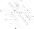
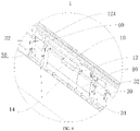
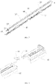
FIG. 1 is a perspective view of a splicing member according to an embodiment of the present application; -
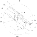
FIG. 2 is a perspective view of a splicing member according to an embodiment of the present application from another viewing angle; -
FIG. 3 is an exploded view of two splicing members according to an embodiment of the present application; -
FIG. 4 is a diagram illustrating a splicing process of two splicing members according to an embodiment of the present application; -
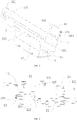
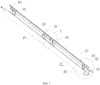
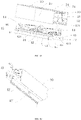
FIG. 5 is a diagram illustrating a splicing structure of adjacent housings according to an embodiment of the present application; -
FIG. 6 is a partial view of a spliced position inFIG. 5 ; -
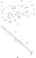
FIG. 7 is a diagram illustrating a positional relationship between a splicing member and a connector and a housing according to an embodiment of the present application; -
FIG. 8 is a partially enlarged view of a position I inFIG. 7 ; -
FIG. 9 is a partially enlarged view of a position II inFIG. 7 ; -
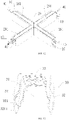
FIG. 10 is a schematic structural diagram of a first transition module according to an embodiment of the present application; -
FIG. 11 is a schematic structural diagram of a second transition module according to an embodiment of the present application; -
FIG. 12 is a schematic structural diagram of a third transition module according to an embodiment of the present application; -
FIG. 13 is a perspective view of a connector according to an embodiment of the present application; -
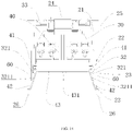
FIG. 14 is a view of connected end faces of a connector, a photoelectric module, and a housing according to an embodiment of the present application; -
FIG. 15 is an exploded view of a photoelectric module and a housing according to an embodiment of the present application; -
FIG. 16 is a connection structure diagram of a photoelectric module and a housing according to an embodiment of the present application; -
FIG. 17 is a splicing structure diagram of a photoelectric module and a housing according to an embodiment of the present application; -
FIG. 18 is a partial view ofFIG. 17 ; -
FIG. 19 is a first connection structure diagram of an electrical connection terminal according to an embodiment of the present application; -
FIG. 20 is a second connection structure diagram of an electrical connection terminal according to an embodiment of the present application; -
FIG. 21 is a third connection structure diagram of an electrical connection terminal according to an embodiment of the present application; -
FIG. 22 is a diagram illustrating distribution of light sources according to an embodiment of the present application; -
FIG. 23 is an exploded view of a housing and a light distribution component according to an embodiment of the present application; -
FIG. 24 is an exploded view of a linear lamp according to an embodiment of the present application; and -
FIG. 25 is an entire diagram of a linear lamp according to an embodiment of the present application. - Names and reference numerals of parts in figures are as follows:
Splicingmember 10;Main body 11;First side body 12; First snap-fit part 121;Guide slope 1211; First snap-fit surface 1212; Through-hole 122; Avoidingspace 124; Reinforcingrib 125;Second side body 13; Second snap-fit part 131;Groove 1311; Second snap-fit surface 1312;Second guide part 132; Accommodatingspace 14;First connection body 15;Second connection body 16;Housing 20; First mountingspace 21; Strip-shapedrib 22;Slot 23;Bottom plate 24;Side plate 25; snap-fit strip 26;Transition module 29;Connector 30; Accommodatingcavity 31;Side arm 32;Bottom arm 33;Hook 321;Slope 3211;Photoelectric module 40; snap-fit body 41; Liningplate 42;Opening 421;Light source plate 43;Light source 431;Electrical connection terminal 44;Female head 441;Male head 442;Conversion terminal 45;Power supply 46;Light distribution component 50;Movement gap 60; andEnd cover 70. - In order to make objects, technical solutions and advantages of the present application apparent, the technical solutions of the embodiment will be described in a clearly and fully understandable way in connection with the embodiments of the present application and the drawings related to the embodiments of the present application. It is obvious that the described embodiments are just a part but not all of the embodiments of the present application. Based on the described embodiments herein, those skilled in the art can obtain other embodiment(s), without any inventive work, which should be within the protection scope of the present application.
- As shown in
FIG. 3 andFIG. 4 , the embodiment discloses a linear lamp. The linear lamp includes ahousing 20 and asplicing member 10, where the number of thehousing 20 is at least two. - Each of the splicing
member 10 includes amain body 11, afirst side body 12, and asecond side body 13, wherein thefirst side body 12 and thesecond side body 13 are connected to and distributed on two opposite sides of themain body 11 respectively. A first snap-fit part 121 is provided in thefirst side body 12. A second snap-fit part 131 is provided in thesecond side body 13. The splicingmember 10 has specific elasticity. For example, the splicingmember 10 may be a metal sheet. Themain body 11, thefirst side body 12, and thesecond side body 13 may be integrally formed, or themain body 11, thefirst side body 12, and thesecond side body 13 may be welded and connected together. - The first snap-
fit part 121 of thefirst splicing member 10 and the second snap-fit part 131 of thesecond splicing member 10 are in snap-fit connection. The second snap-fit part 131 of thefirst splicing member 10 and the first snap-fit part 121 of thesecond splicing member 10 are in snap-fit connection. That is, the first snap-fit part 121 of one splicingmember 10 and the second snap-fit part 131 of theadjacent splicing member 10 are in snap-fit connection. Therefore, theadjacent splicing members 10 are spliced together. After thesplicing member 10 is mounted at an end of thehousing 20, theadjacent splicing members 10 are spliced together, so that the twoadjacent housings 20 are spliced together. - In the embodiment, the splicing
member 10 is simple in structure and convenient to be spliced. The twosplicing members 10 are opposite in placement direction and are connected to theadjacent housings 20 respectively, and then the twosplicing members 10 are spliced, so that the twoadjacent housings 20 can be rapidly spliced together. In the embodiment, when thehousings 20 are connected, thesplicing members 10 with a same structure are used, so that design cost can be reduced. - As shown in
FIG. 7 , thesplicing members 10 are mounted at two ends of eachhousing 20 respectively. As shown inFIG. 10 to FIG. 12 , thehousing 20 has two or more ends, and the splicingmember 10 is mounted at each end. As shown inFIG. 24 , anend cover 70 is provided on an outer end of thehousing 20 located on a tail portion of the linear lamp, and the splicingmember 10 is mounted at an inner end. Thehousings 20 with different structures and thehousings 20 in different positions are provided with different numbers ofsplicing members 10, which can be arranged according to actual needs. - As shown in
FIG. 15 , thehousing 20 includes abottom plate 24 and twoside plates 25, wherein thebottom plate 24 and the twoside plates 25 are connected and enclose a first mountingspace 21. After the twoadjacent housings 20 are spliced together, facing end faces are attached together, and thesplicing members 10 are entirely located in the first mountingspace 21. In the embodiment, due to the structure of thesplicing members 10, thesplicing members 10 can still be spliced together after being detached from thehousing 20. Referring toFIG. 4 andFIG. 7 , thefirst side body 12 of one splicingmember 10 is limited in an outward direction by an inner side wall of oneside plate 25 of thehousing 20, and thefirst side body 12 of theadjacent splicing member 10 is limited in an outward direction by an inner side wall of theother side plate 25 of thehousing 20. Because thesplicing members 10 have specific elasticity, thesecond side body 13 is located on an inner side of thefirst side body 12 and can exert outward extrusion force on thefirst side body 12. Theside plate 25 has the function that when thesecond side body 13 outward extrudes thefirst side body 12, theside plate 25 can prevent thefirst side body 12 from moving outward, so that thesecond side body 13 is closely attached to thefirst side body 12, and the first snap-fit part 121 and the second snap-fit part 131 can be more reliably in snap-fit connection. - In the embodiment, the
splicing members 10 have specific elasticity, so that the first snap-fit part 121 and the second snap-fit part 131 can more easily achieve snap-fit connection. In addition, the limiting effect of theside plate 25 prevents thefirst side body 12 from moving outward due to elasticity. - As shown in
FIG. 1 andFIG. 2 , thefirst side body 12, thesecond side body 13, and themain body 11 enclose anaccommodating space 14. As shown inFIG. 7 andFIG. 9 , the splicingmember 10 is inserted into the first mountingspace 21, and themain body 11 is fixed to the bottom plate of thehousing 20 by using a screw, so that the splicingmember 10 is fixed in thehousing 20, and theaccommodating space 14 communicates with the first mountingspace 21. Themain body 11 is attached to thebottom plate 24 of thehousing 20, and thefirst side body 12 and thesecond side body 13 are parallel to and closer to the twoside plates 25 respectively, so that the splicingmember 10 in the embodiment not only can rapidly connect the twoadjacent housings 20, but also has the advantages of being small in occupied space and capable of accommodating other parts, for example, theaccommodating space 14 may accommodate thephotoelectric module 40. - As shown in
FIG. 9 , two strip-shapedribs 22 spaced from each other are provided on the inner side wall of theside plate 25, the strip-shapedribs 22 extend in a length direction of thehousing 20, aslot 23 is formed between the two strip-shapedribs 22, and a length direction of theslot 23 is consistent with the length direction of thehousing 20. The splicingmember 10 further includes afirst connection body 15, one end of thefirst connection body 15 is connected to themain body 11, and the other end of thefirst connection body 15 is bent away from thesecond side body 13 toward theslot 23 and is connected to thefirst side body 12. The splicingmember 10 further includes asecond connection body 16, one end of thesecond connection body 16 is connected to themain body 11, and the other end of thesecond connection body 16 is bent away from thefirst side body 12 toward anotherslot 23 and is connected to thesecond side body 13. When the splicingmember 10 is inserted into the first mountingspace 21 from a port of thehousing 20, in the presence of a bent part of thefirst connection body 15, thefirst side body 12 can be inserted into theslot 23. In the presence of a bent part of thesecond connection body 16, thesecond side body 13 can be closer to theslot 23, or thesecond side body 13 is also inserted into theslot 23. In this case, as shown inFIG. 6 , thefirst side body 12 is limited in an outward direction by a slot bottom of theslot 23. Theslot 23 can also limit thefirst side body 12 in an up and down direction and prevent thefirst side body 12 from dislocation, so that the first snap-fit part 121 and the second snap-fit part 131 are easily in snap-fit connection. The up and down direction herein is consistent with a width direction of theslot 23. - In the embodiment, the
first side body 12 and thesecond side body 13 of the linear lamp both extend in the length direction of thehousing 20, the length of thefirst side body 12 is larger, and thesecond side body 13 may be disposed directly facing the middle of thefirst side body 12. As shown inFIG. 1 , a left end of thefirst side body 12 and a right end of thesecond side body 13 are different-side ends, or a right end of thefirst side body 12 and a left end of thesecond side body 13 are different-side ends. The first snap-fit part 121 and the second snap-fit part 131 are distributed at the different-side ends of thefirst side body 12 and thesecond side body 13, so that the twosplicing members 10 can have more overlapped parts when being spliced, and space can be saved. - A through-
hole 122 is provided on thefirst side body 12, the first snap-fit part 121 is disposed adjacent to the through-hole 122, and an edge of the first snap-fit part 121 forms a side wall of the through-hole 122. The first snap-fit part 121 is formed by partially recessing thefirst side body 12 toward thesecond side body 13, which is beneficial to reduce the number of components and parts. The first snap-fit part 121 protrudes out of an inner side surface of thefirst side body 12. The inner side surface of thefirst side body 12 is a surface facing toward thesecond side body 13. - As shown in
FIG. 8 , the through-hole 122 can accommodate a portion of the second snap-fit part 131, so that a contact area of the first snap-fit part 121 and the second snap-fit part 131 is relatively larger, which further improves reliability of the snap-fit connection of the first snap-fit part 121 and the second snap-fit part 131. Aguide slope 1211 is provided on a surface of the first snap-fit part 121 facing toward thesecond side body 13, and theguide slope 1211 is used to improve splicing smoothness of the twosplicing members 10. - The second snap-
fit part 131 is formed by partially recessing thesecond side body 13 away from thefirst side body 12, which is beneficial to reduce the number of components and parts. The second snap-fit part 131 protrudes out of an outer side surface of thesecond side body 13. The outer side surface of thesecond side body 13 is a surface facing away from thefirst side body 12. The second snap-fit part 131 extends from an end face of thesecond side body 13 to the other end of thesecond side body 13, agroove 1311 is provided on the second snap-fit part 131, and thegroove 1311 extends from an end face of thesecond side body 13 to the other end of thesecond side body 13. Asecond guide part 132 bent toward thefirst side body 12 is provided at the other end of thesecond side body 13, thereby improving splicing smoothness of the twosplicing members 10. - As shown in
FIG. 4 , surfaces of the snap-fit connection of the first snap-fit part 121 and the second snap-fit part 131 are a first snap-fit surface 1212 and a second snap-fit surface 1312 respectively, and the first snap-fit surface 1212 and the second snap-fit surface 1312 face each other and are in snap-fit connection. In the presence of thegroove 1311, during detachment, a tool is easily inserted into thegroove 1311 and pries the first snap-fit part 121 and the second snap-fit part 131 so as to separate the first snap-fit part 121 and the second snap-fit part 131. - A protruding height of the second snap-
fit part 131 is less than a depth of the through-hole 122, that is, the depth of the through-hole 122 is larger, so that the second snap-fit part 131 cannot extend out of an outer surface of thefirst side body 12, thefirst side body 12 is attached to the slot bottom of theslot 23, occupied space is saved, and it can be ensured that the slot bottom of theslot 23 can limit thefirst side body 12. The outer surface of thefirst side body 12 is a surface of thefirst side body 12 facing away from thesecond side body 13. The slot bottom of theslot 23 is a side wall of thehousing 20 located in theslot 23. - Because the
first side body 12 has specific elasticity and a larger length, and a reinforcingrib 125 is provided on thefirst side body 12 and are used to increase insertion reliability of thefirst side body 12 and theslot 23. The reinforcingrib 125 may extend in the length direction of thefirst side body 12. -
FIG. 5 andFIG. 6 show two straight-line shape housings 20. As shown inFIG. 10 to FIG. 12 , thehousing 20 includes atransition module 29, and thetransition module 29 is used at a turn. Thetransition module 29 includes at least twoextension parts 291, and the at least twoextension parts 291 are perpendicular to each other. - As shown in
FIG. 10 , the number of theextension parts 291 is two, and the twoextension parts 291 are perpendicular to form an L-shaped structure. As shown inFIG. 11 , the number of theextension parts 291 is three, two of theextension parts 291 are located on a same straight line, and the other one is perpendicular to the twoextension parts 291 to form a T-shaped structure. As shown inFIG. 12 , the number of theextension parts 291 is four, and the fourextension parts 291 are perpendicular to form a cross-shaped structure. - In the embodiment, the linear lamp further includes a
connector 30 and aphotoelectric module 40, where the number of thephotoelectric module 40 is at least two, thephotoelectric module 40 is mounted in thehousing 20 by using theconnector 30, and the two adjacentphotoelectric modules 40 are electrically spliced together. As shown inFIG. 17 , only onephotoelectric module 40 may be mounted in the first mountingspace 21 of eachhousing 20. Thephotoelectric module 40 extends in the length direction of thehousing 20. - As shown in
FIG. 17 and FIG. 18 ,electrical connection terminals 44 are provided at two ends of thephotoelectric module 40, and theelectrical connection terminals 44 of the adjacentphotoelectric modules 40 are electrically connected, so that the adjacentphotoelectric modules 40 are connected together. - As shown in
FIG. 19 , theelectrical connection terminals 44 at the two ends of eachphotoelectric module 40 may be different in structure, for example, may be afemale head 441 and amale head 442 respectively. Thefemale head 441 of onephotoelectric module 40 and themale head 442 of the otherphotoelectric module 40 are in inserting connection cooperation. As shown inFIG. 20 and FIG. 21 , when directions of thefemale head 441 and themale head 442 need to be changed, oneconversion terminal 45 may be added. The female heads 441 may be arranged at two ends of theconversion terminal 45, or the male heads 442 may be arranged at two ends of theconversion terminal 45. The type of theconversion terminal 45 may be selected according to needs. - The
housing 20 has an open end opposite to thebottom plate 24. Theconnector 30 is inserted into the first mountingspace 21 from the open end. As shown inFIG. 13 , theconnector 30 has abottom arm 33 and twoside arms 32, thebottom arm 33 and the twoside arms 32 are connected and enclose anaccommodating cavity 31, theconnector 30 has three open ends like thehousing 20. Thephotoelectric module 40 is inserted into theaccommodating cavity 31 from the open end of theconnector 30 opposite to thebottom arm 33. Thephotoelectric module 40 may be partially or entirely located in theaccommodating cavity 31. Thebottom arm 33 of theconnector 30 is fixed to thebottom plate 24 of thehousing 20 by using a screw. Theconnector 30 is simple in structure and has a small occupied space. Thephotoelectric module 40 includes alight source plate 43, alight source 431 disposed on an outer side surface of thelight source plate 43, and apower supply 46 located on an inner side of thelight source plate 43, theconnector 30 encloses anaccommodating cavity 31, and thelight source plate 43, thelight source 431, and thepower supply 46 are located in theaccommodating cavity 31. The inner side of thelight source plate 43 faces toward thebottom arm 33 and also faces toward thebottom plate 24. - The
photoelectric module 40 and theconnector 30 are in snap-fit connection, so that thephotoelectric module 40 is convenient to be mounted. Thephotoelectric module 40 comprises a snap-fit body 41, ahook 321 is formed on an inner side wall of theconnector 30, and the snap-fit body 41 and thehook 321 are in snap-fit connection. Thehook 321 comprises aslope 3211 for thephotoelectric module 40 to be conveniently inserted into theaccommodating cavity 31. - The
side arm 32 of theconnector 30 is an elastic arm in snap-fit connection with thephotoelectric module 40. As shown inFIG. 14 , amovement gap 60 is provided between theside arm 32 and the inner side wall of thehousing 20, and themovement gap 60 is used for theside arm 32 to move. Thephotoelectric module 40 includes alining plate 42 with anopening 421. At least a portion of theside arm 32 is disposed facing theopening 421, so that theside arm 32 can be pushed through theopening 421. Thehook 321 is formed on an inner surface of theside arm 32. - In the embodiment, the
adjacent housings 20 are spliced together first, and then thephotoelectric module 40 is mounted in the first mountingspace 21 of thehousing 20. In this case, thephotoelectric module 40 may be moved in a length direction of thephotoelectric module 40 until theopening 421 is aligned with theside arm 32, so that theside arms 32 can be pushed through theopening 421. - The
lining plate 42 may be a reflector. As shown inFIG. 14 to FIG. 16 , thelining plates 42 are distributed on two sides of thelight source plate 43 and configured to distribute light for thelight source 431 on thelight source plate 43, so that light emitting efficiency is improved. The reflector blocks thehook 321, theside arm 32 may be pressed through theopening 421, and thehook 321 may be separated from the snap-fit body 41, so that thephotoelectric module 40 can be detached from theconnector 30. - As shown in
FIG. 9 , thefirst side body 12 is longer, and theside arm 32 of theconnector 30 closer to the end of thehousing 20 and the inner side wall of thehousing 20 are separated by thefirst side body 12. As shown inFIG. 8 , thefirst side body 12 comprises an avoidingspace 124 deviating from the first snap-fit part 121, and the avoidingspace 124 forms a portion of themovement gap 60. The avoidingspace 124 is disposed directly facing theside arm 32. The avoidingspace 124 is used to ensure that theside arm 32 has a sufficient space to move, so that theside arm 32 can be separated from the snap-fit body 41 when theside arm 32 is pushed toward the inner wall of thehousing 20 through theopening 421. - Provided that the
second side body 13 is located between theside arm 32 of theconnector 30 and the inner side wall of thehousing 20, an avoiding space also needs to be provided on thesecond side body 13, so that thephotoelectric module 40 can be conveniently detached. - As shown in
FIG. 22 , several groups oflight sources 431 arranged at intervals in a length direction are provided on thelight source plate 43, and after the two adjacentphotoelectric modules 40 are spliced, distances between two adjacent groups oflight sources 431 in any position are the same, so that light emitting uniformity can be ensured. Specifically, distances between the two adjacent groups oflight sources 431 in a spliced position need to be the same as distances between the two adjacent groups oflight sources 431 in another position. The distances are still deemed as the same within a tolerance range of a machining error. - As shown in
FIG. 23 , the linear lamp further includes alight distribution component 50, where thelight distribution component 50 is an integrally formed member, and theadjacent housings 20 are both connected to thelight distribution component 50. Thelight distribution component 50 may be a diffusion cover. As shown inFIG. 14 andFIG. 23 , a snap-fit strip 26 is provided on the inner wall of thehousing 20, the snap-fit strip 26 extends in the length direction of thehousing 20, and a distance between the snap-fit strip 26 and thebottom plate 24 of thehousing 20 is greater than a distance between any strip-shapedrib 22 and thebottom plate 24. The snap-fit strip 26 and thelight distribution component 50 are in snap-fit connection, so that the connection is facilitated. The entire diffusion cover facilitates improving light emitting uniformity. - As shown in
FIG. 10 to FIG. 12 , a mounting cavity is provided in theextension part 291, thephotoelectric module 40 is mounted in the mounting cavity, and the splicingmember 10 is mounted at an outer end of theextension part 291. Thetransition module 29 is spliced with the straight-line shape housing 20 by using thesplicing member 10, and thephotoelectric module 40 in thetransition module 29 is spliced with thephotoelectric module 40 in the straight-line shape housing 20. - As shown in
FIG. 24 and FIG. 25 , end covers 70 are mounted at two ends of thehousing 20, and the end covers 70 may be connected to thehousing 20 by using screws. As shown inFIG. 24 and FIG. 25 , the number of thehousings 20 is two, or the number of thehousings 20 may be two or more. For example, a lamp shell of the linear lamp is formed by splicing sixhousings 20. The sixhousings 20 may be distributed on one straight line, or may be distributed on different straight lines by using thetransition module 29. - In the embodiment, the
adjacent housings 20 of the linear lamp are convenient to be spliced, the adjacentphotoelectric modules 40 are convenient to be spliced, thelight distribution component 50 is convenient to be mounted, and the linear lamp is uniform in light emitting. - What are described above is related to the specific embodiments of the present application only and not limitative to the scope of the present application. For those skilled in the art, the present application may have various changes and modifications. Any modification, equivalent replacement, improvement and the like made within the spirit and principle of the present application shall be included within the scope of the claims of the present application.
Claims (20)
- A linear lamp, comprising housings (20) and a splicing member (10), wherein a number of the housings (20) is at least two, the splicing member (10) is mounted at an end of each of the housings (20), and the two adjacent splicing members (10) are in snap-fit connection to splice the two adjacent housings (20) together.
- The linear lamp according to claim 1, wherein facing end faces of the two adjacent housings (20) are attached to each other.
- The linear lamp according to claim 1, wherein the splicing member (10) comprises a main body (11), a first side body (12), and a second side body (13), the first side body (12) and the second side body (13) are connected to and distributed on opposite sides of the main body (11), the first side body (12) comprises a first snap-fit part (121), the second side body (13) comprises a second snap-fit part (131), and the first snap-fit part (121) of one splicing member (10) and the second snap-fit part (131) of the splicing member (10) adjacent to the one splicing member are in snap-fit connection.
- The linear lamp according to claim 3, wherein the first side body (12) of one splicing member (10) is limited in an outward direction by one of inner side walls of the housing (20), the first side body (12) of the splicing member (10) adjacent to the one splicing member (10) is limited in an outward direction by another of the inner side walls of the housing (20), and the second side body (13) is located on an inner side of the first side body (12) and exerts outward extrusion force on the first side body (12).
- The linear lamp according to claim 4, wherein the inner side wall comprises a slot (23), and the first side body (12) is inserted in the slot (23).
- The linear lamp according to claim 5, wherein the splicing member (10) further comprises a first connection body (15) and a second connection body (16), the first connection body (15) is connected to the main body (11) and the first side body (12), the second connection body (16) is connected to the main body (11) and the second side body (13), and the first connection body (15) is bent toward the inner side wall adjacent to the first connection body (15), and the second connection body (16) is bent toward the inner side wall adjacent to the second connection body (16).
- The linear lamp according to claim 3, wherein the first snap-fit part (121) protrudes out of an inner side surface of the first side body (12).
- The linear lamp according to claim 7, wherein the first side body (12) comprises a through-hole (122) which is disposed adjacent to the first snap-fit part (121), and at least a portion of the second snap-fit part (131) is located in the through-hole (122).
- The linear lamp according to claim 7, wherein the second snap-fit part (131) protrudes out of an outer side surface of the second side body (13).
- The linear lamp according to claim 9, wherein the second snap-fit part (131) extends from one end face of the second side body (13) to another end of the second side body (13), and a groove (1311) is provided on the one end face of the second side body (13).
- The linear lamp according to claim 10, wherein a second guide part (132) bent toward the first side body (12) is provided on the another end.
- The linear lamp according to claim 3, wherein the first side body (12) and the second side body (13) both extend in a length direction of the housing (20), a length of the first side body (12) is greater than a length of the second side body (13), the first snap-fit part (121) of one housing (20) extends into an inner cavity of the housing (20) adjacent to the one housing (20).
- The linear lamp according to claim 1, wherein the linear lamp further comprises a connector (30) and at least two photoelectric modules (40), wherein the photoelectric modules (40) are mounted in the housing (20) by using the connector (30), and the two adjacent photoelectric modules (40) are electrically spliced together.
- The linear lamp according to claim 13, wherein each of the photoelectric modules (40) comprises a light source plate (43), a light source (431) disposed on an outer side surface of the light source plate (43), and a power supply (46) located on an inner side of the light source plate (43), wherein the connector (30) encloses an accommodating cavity (31), and the light source plate (43), the light source (431), and the power supply (46) are located in the accommodating cavity (31).
- The linear lamp according to claim 13, wherein the photoelectric module (40) and the connectors (30) are in snap-fit connection.
- The linear lamp according to claim 15, wherein the photoelectric module (40) includes a snap-fit body (41), the connector (30) comprises a hook (321), and the snap-fit body (41) and the hook (321) are in snap-fit connection.
- The linear lamp according to claim 14, wherein the connector (30) comprises a side arm (32), the side arm (32) is an elastic arm being in snap-fit connection with the photoelectric module (40), a movement gap (60) for the side arm (32) to move is provided between the side arm (32) and the housing (20), and the photoelectric module (40) comprises an opening (421) corresponding to the side arm (32).
- The linear lamp according to claim 17, wherein the first side body (12) or the second side body (13) comprises an avoiding space (124), and the movement gap (60) comprises the avoiding space (124).
- The linear lamp according to claim 13, wherein the photoelectric module (40) includes a plurality of groups of the light sources (431) arranged at intervals in a length direction of the photoelectric module (40), and after the two adjacent photoelectric modules (40) are spliced, distances between two adjacent groups of the light sources (431) in any position are a same.
- The linear lamp according to claim 1, wherein the linear lamp further comprises a light distribution component (50), the light distribution component (50) is an integrally formed member, and the adjacent housings (20) are both connected to the light distribution component (50).
Applications Claiming Priority (3)
| Application Number | Priority Date | Filing Date | Title |
|---|---|---|---|
| CN201910926861.5A CN110566855B (en) | 2019-09-27 | 2019-09-27 | Linear Light |
| CN201921640948.8U CN210373082U (en) | 2019-09-27 | 2019-09-27 | Linear lamp |
| PCT/CN2020/117995 WO2021057941A1 (en) | 2019-09-27 | 2020-09-27 | Linear lamp |
Publications (2)
| Publication Number | Publication Date |
|---|---|
| EP3974704A1 true EP3974704A1 (en) | 2022-03-30 |
| EP3974704A4 EP3974704A4 (en) | 2022-12-21 |
Family
ID=75165592
Family Applications (1)
| Application Number | Title | Priority Date | Filing Date |
|---|---|---|---|
| EP20868357.3A Pending EP3974704A4 (en) | 2019-09-27 | 2020-09-27 | LINEAR LIGHT |
Country Status (3)
| Country | Link |
|---|---|
| US (1) | US11821595B2 (en) |
| EP (1) | EP3974704A4 (en) |
| WO (1) | WO2021057941A1 (en) |
Families Citing this family (6)
| Publication number | Priority date | Publication date | Assignee | Title |
|---|---|---|---|---|
| US11493196B1 (en) * | 2021-04-27 | 2022-11-08 | Taiwan Oasis Technology Co., Ltd. | Assembly structure |
| US12281766B2 (en) | 2022-01-21 | 2025-04-22 | Signify Holding, B.V. | Bracket for linear luminaires |
| CN119487332A (en) | 2022-07-01 | 2025-02-18 | 昕诺飞控股有限公司 | Lighting joint system |
| US12546455B2 (en) | 2022-07-01 | 2026-02-10 | Signify Holding B.V. | Optic for backlight control |
| CN221237777U (en) * | 2023-11-30 | 2024-06-28 | 深圳市思坎普科技有限公司 | Quick-assembled linear lights |
| US12247719B2 (en) | 2024-05-17 | 2025-03-11 | Huamin LIU | Solar magnetic suction linear lamp |
Family Cites Families (14)
| Publication number | Priority date | Publication date | Assignee | Title |
|---|---|---|---|---|
| DE1032397B (en) * | 1957-03-04 | 1958-06-19 | Koerting & Mathiesen Ag | Device for connecting individual lights to light strips |
| US3599911A (en) * | 1969-11-06 | 1971-08-17 | Sunbeam Lighting Co Inc | Means for end-to-end assembly of elongated fluorescent lamp ceiling fixtures |
| CN101033835A (en) * | 2006-03-10 | 2007-09-12 | 宁波安迪光电科技有限公司 | Luminescence device and connecting device matched with same |
| CA2671360C (en) * | 2008-07-08 | 2017-01-10 | Virginia Optoelectronics, Inc. | Modular led lighting systems and flexible or rigid strip lighting devices |
| JP5524656B2 (en) * | 2009-07-13 | 2014-06-18 | ローム株式会社 | LED lighting device |
| EP2295847A2 (en) * | 2009-09-15 | 2011-03-16 | Broll Systemtechnik KG | Lighting fixture, in particular tunnel lighting fixture |
| DE202010014200U1 (en) * | 2010-10-13 | 2010-12-16 | Ridi - Leuchten Gmbh | trunking |
| US10215380B2 (en) * | 2016-10-20 | 2019-02-26 | Axis Lighting Inc. | Couplers for light fixtures |
| CN107477529A (en) * | 2017-08-02 | 2017-12-15 | 西蒙电气(中国)有限公司 | Light fixture bindiny mechanism and the light fixture with light fixture bindiny mechanism |
| CN207065501U (en) * | 2017-08-08 | 2018-03-02 | 厦门通士达照明有限公司 | A kind of splice and its splicing type lamp |
| EP3470732A1 (en) * | 2017-10-13 | 2019-04-17 | Mass Technology (H.K.) Ltd. | Light-emitting joint for connection of luminaires and lighting device comprising the same |
| US11421860B2 (en) * | 2017-11-30 | 2022-08-23 | Hubbell Lighting, Inc. | Optic support for a light fixture |
| CN209130665U (en) * | 2018-12-19 | 2019-07-19 | 广东昇辉电子控股有限公司 | A kind of seamless spliced flat lamp |
| CN110566855B (en) * | 2019-09-27 | 2024-09-27 | 欧普照明股份有限公司 | Linear Light |
-
2020
- 2020-09-27 EP EP20868357.3A patent/EP3974704A4/en active Pending
- 2020-09-27 WO PCT/CN2020/117995 patent/WO2021057941A1/en not_active Ceased
-
2021
- 2021-12-29 US US17/565,299 patent/US11821595B2/en active Active
Also Published As
| Publication number | Publication date |
|---|---|
| EP3974704A4 (en) | 2022-12-21 |
| WO2021057941A1 (en) | 2021-04-01 |
| US11821595B2 (en) | 2023-11-21 |
| US20220120392A1 (en) | 2022-04-21 |
Similar Documents
| Publication | Publication Date | Title |
|---|---|---|
| US11821595B2 (en) | Linear lamp | |
| CN110566855B (en) | Linear Light | |
| CN211146154U (en) | Line lamp and line lamp system | |
| US6520799B1 (en) | Stacked connector assembly | |
| KR20160095484A (en) | Line type lighting device | |
| EP2665133A1 (en) | Connector | |
| CN112751219B (en) | Electrical terminal and electrical connector | |
| EP3798503A1 (en) | Linear lighting | |
| CN210373082U (en) | Linear lamp | |
| CN205828722U (en) | Plug connectors for transceiver modules | |
| CN216698783U (en) | Floating board-to-board connector and female seat thereof | |
| KR20050014680A (en) | Connector small in size and simple in structure | |
| CN105207006A (en) | Electric connector combination | |
| CN110391562B (en) | A transfer connector and connector assembly | |
| CN112787161B (en) | Floating socket and floating connector | |
| CN210535867U (en) | Electric connector, electric connector assembly and panel lamp combination | |
| CN205592902U (en) | Combination formula line lamp and connect thereof | |
| CN205592725U (en) | Line lamp | |
| CN220253547U (en) | Electrical contact and electrical connector | |
| US9362651B2 (en) | Locking structure of terminal fitting and bulb socket | |
| EP3851736A1 (en) | Lamp convenient to install and diverse application module using same | |
| CN116315776B (en) | Electric connector and electric connector assembly | |
| CN212961020U (en) | Illumination module and illumination lamp | |
| CN217464154U (en) | Line lamp and banks of butt joint | |
| CN214379147U (en) | Conductive connection structure and assembled lamp |
Legal Events
| Date | Code | Title | Description |
|---|---|---|---|
| STAA | Information on the status of an ep patent application or granted ep patent |
Free format text: STATUS: THE INTERNATIONAL PUBLICATION HAS BEEN MADE |
|
| PUAI | Public reference made under article 153(3) epc to a published international application that has entered the european phase |
Free format text: ORIGINAL CODE: 0009012 |
|
| STAA | Information on the status of an ep patent application or granted ep patent |
Free format text: STATUS: REQUEST FOR EXAMINATION WAS MADE |
|
| 17P | Request for examination filed |
Effective date: 20211221 |
|
| AK | Designated contracting states |
Kind code of ref document: A1 Designated state(s): AL AT BE BG CH CY CZ DE DK EE ES FI FR GB GR HR HU IE IS IT LI LT LU LV MC MK MT NL NO PL PT RO RS SE SI SK SM TR |
|
| RIC1 | Information provided on ipc code assigned before grant |
Ipc: F21V 15/01 20060101ALI20220826BHEP Ipc: F21S 8/00 20060101ALI20220826BHEP Ipc: F21V 21/005 20060101AFI20220826BHEP |
|
| REG | Reference to a national code |
Ref country code: DE Ref legal event code: R079 Free format text: PREVIOUS MAIN CLASS: F21S0008000000 Ipc: F21V0021005000 |
|
| A4 | Supplementary search report drawn up and despatched |
Effective date: 20221122 |
|
| RIC1 | Information provided on ipc code assigned before grant |
Ipc: F21V 15/01 20060101ALI20221116BHEP Ipc: F21S 8/00 20060101ALI20221116BHEP Ipc: F21V 21/005 20060101AFI20221116BHEP |
|
| DAV | Request for validation of the european patent (deleted) | ||
| DAX | Request for extension of the european patent (deleted) | ||
| STAA | Information on the status of an ep patent application or granted ep patent |
Free format text: STATUS: EXAMINATION IS IN PROGRESS |
|
| 17Q | First examination report despatched |
Effective date: 20241209 |