EP3974674A1 - Cam clutch - Google Patents
Cam clutch Download PDFInfo
- Publication number
- EP3974674A1 EP3974674A1 EP20810038.8A EP20810038A EP3974674A1 EP 3974674 A1 EP3974674 A1 EP 3974674A1 EP 20810038 A EP20810038 A EP 20810038A EP 3974674 A1 EP3974674 A1 EP 3974674A1
- Authority
- EP
- European Patent Office
- Prior art keywords
- cam
- cams
- attitude
- outer race
- inner race
- Prior art date
- Legal status (The legal status is an assumption and is not a legal conclusion. Google has not performed a legal analysis and makes no representation as to the accuracy of the status listed.)
- Granted
Links
Images



Classifications
-
- F—MECHANICAL ENGINEERING; LIGHTING; HEATING; WEAPONS; BLASTING
- F16—ENGINEERING ELEMENTS AND UNITS; GENERAL MEASURES FOR PRODUCING AND MAINTAINING EFFECTIVE FUNCTIONING OF MACHINES OR INSTALLATIONS; THERMAL INSULATION IN GENERAL
- F16D—COUPLINGS FOR TRANSMITTING ROTATION; CLUTCHES; BRAKES
- F16D41/00—Freewheels or freewheel clutches
- F16D41/06—Freewheels or freewheel clutches with intermediate wedging coupling members between an inner and an outer surface
- F16D41/08—Freewheels or freewheel clutches with intermediate wedging coupling members between an inner and an outer surface with provision for altering the freewheeling action
- F16D41/084—Freewheels or freewheel clutches with intermediate wedging coupling members between an inner and an outer surface with provision for altering the freewheeling action the intermediate coupling members wedging by pivoting or rocking
-
- F—MECHANICAL ENGINEERING; LIGHTING; HEATING; WEAPONS; BLASTING
- F16—ENGINEERING ELEMENTS AND UNITS; GENERAL MEASURES FOR PRODUCING AND MAINTAINING EFFECTIVE FUNCTIONING OF MACHINES OR INSTALLATIONS; THERMAL INSULATION IN GENERAL
- F16D—COUPLINGS FOR TRANSMITTING ROTATION; CLUTCHES; BRAKES
- F16D41/00—Freewheels or freewheel clutches
- F16D41/06—Freewheels or freewheel clutches with intermediate wedging coupling members between an inner and an outer surface
- F16D41/069—Freewheels or freewheel clutches with intermediate wedging coupling members between an inner and an outer surface the intermediate members wedging by pivoting or rocking, e.g. sprags
-
- F—MECHANICAL ENGINEERING; LIGHTING; HEATING; WEAPONS; BLASTING
- F16—ENGINEERING ELEMENTS AND UNITS; GENERAL MEASURES FOR PRODUCING AND MAINTAINING EFFECTIVE FUNCTIONING OF MACHINES OR INSTALLATIONS; THERMAL INSULATION IN GENERAL
- F16D—COUPLINGS FOR TRANSMITTING ROTATION; CLUTCHES; BRAKES
- F16D41/00—Freewheels or freewheel clutches
- F16D41/06—Freewheels or freewheel clutches with intermediate wedging coupling members between an inner and an outer surface
- F16D41/069—Freewheels or freewheel clutches with intermediate wedging coupling members between an inner and an outer surface the intermediate members wedging by pivoting or rocking, e.g. sprags
- F16D41/07—Freewheels or freewheel clutches with intermediate wedging coupling members between an inner and an outer surface the intermediate members wedging by pivoting or rocking, e.g. sprags between two cylindrical surfaces
-
- F—MECHANICAL ENGINEERING; LIGHTING; HEATING; WEAPONS; BLASTING
- F16—ENGINEERING ELEMENTS AND UNITS; GENERAL MEASURES FOR PRODUCING AND MAINTAINING EFFECTIVE FUNCTIONING OF MACHINES OR INSTALLATIONS; THERMAL INSULATION IN GENERAL
- F16D—COUPLINGS FOR TRANSMITTING ROTATION; CLUTCHES; BRAKES
- F16D41/00—Freewheels or freewheel clutches
- F16D41/06—Freewheels or freewheel clutches with intermediate wedging coupling members between an inner and an outer surface
- F16D41/08—Freewheels or freewheel clutches with intermediate wedging coupling members between an inner and an outer surface with provision for altering the freewheeling action
-
- F—MECHANICAL ENGINEERING; LIGHTING; HEATING; WEAPONS; BLASTING
- F16—ENGINEERING ELEMENTS AND UNITS; GENERAL MEASURES FOR PRODUCING AND MAINTAINING EFFECTIVE FUNCTIONING OF MACHINES OR INSTALLATIONS; THERMAL INSULATION IN GENERAL
- F16D—COUPLINGS FOR TRANSMITTING ROTATION; CLUTCHES; BRAKES
- F16D41/00—Freewheels or freewheel clutches
- F16D41/06—Freewheels or freewheel clutches with intermediate wedging coupling members between an inner and an outer surface
- F16D41/08—Freewheels or freewheel clutches with intermediate wedging coupling members between an inner and an outer surface with provision for altering the freewheeling action
- F16D41/086—Freewheels or freewheel clutches with intermediate wedging coupling members between an inner and an outer surface with provision for altering the freewheeling action the intermediate members being of circular cross-section and wedging by rolling
- F16D41/088—Freewheels or freewheel clutches with intermediate wedging coupling members between an inner and an outer surface with provision for altering the freewheeling action the intermediate members being of circular cross-section and wedging by rolling the intermediate members being of only one size and wedging by a movement not having an axial component, between inner and outer races, one of which is cylindrical
Definitions
- the present invention relates to a cam clutch configured to be switchable between a free state that allows relative rotation between an outer race and an inner race and a locked state that prohibits relative rotation between the outer race and the inner race.
- Some types of two-way clutches are configured to switch between a locked state that prohibits relative rotation between the inner race and the outer race (transmits the rotary force) and a free state that allows relative rotation between the inner race and the outer race (interrupts the rotary force) by tilting cams or sprags (see, for example, Patent Literature 1 and Patent Literature 2).
- Patent Literature 3 describes a clutch configured to be switchable among three operating modes, i.e., two-way free mode allowing rotation in both forward and reverse directions, one-way lock mode allowing rotation only in the forward direction, and one-way lock mode allowing rotation only in the reverse direction, by controlling a retainer that retains both first sprags and second sprags, which are biased by biasing means toward opposite directions in which they lock rotation.
- the two-way clutch described in Patent Literature 1 switches the states of engagement and separation between an input-side rotary member and an output-side rotary member by means of sprags that are tilted in the same direction as the rotation direction of the input-side rotary member when the input-side rotary member is rotated relative to the output-side rotary member. This poses the problem of poor responsiveness due to the time lost when the rotation direction is switched.
- the two-way clutch described in Patent Literature 2 entails the same problem.
- cams are circumferentially equally spaced by the retainer, the cams are, in actuality, disposed movably within a certain range of angles in respective pockets of the retainer, so that there are variations in the position (attitude) of adjacent cams, and the operation timing of the cams varied easily.
- the present invention solves these problems, with an aim to provide a cam clutch capable of switching from one operating mode to another and offering improved stability of clutch operations and high responsiveness.
- a cam clutch including: an inner race and an outer race that are coaxial and rotatable relative to each other; a plurality of cams circumferentially arranged at intervals between the inner race and the outer race; a biasing means biasing each of the plurality of cams so that each of the plurality of cams makes contact with the inner race and the outer race; and an operating mode switch means including a cam attitude change part that is drivable independently of rotation of the inner race and the outer race to forcibly tilt the cams, wherein a load support point is located radially between a load application point of the cam attitude change part on the cam and a distal contact point of the cam on a raceway that is one of the inner race and the outer race positioned on a radially distal side relative to the load application point, a radial distance between the load application point and the load support point being larger than a radial distance between the load support point and the distal contact point.
- the circumferential position of each of the plurality of cams is restricted and the positional relationship between adjacent cams and the attitude of the cams are kept consistent, and therefore behavioral variations of cams when the cam attitude change part is driven to tilt the cams can be avoided. Since the distance between the load application point and the load support point can be set sufficiently large, a larger moment acts on the cams when the cam attitude change part moves, meaning that the attitude of the cams can be changed with a smaller force and with less influence of production variations of components. The stability of clutch operations can thus be improved and high responsiveness can be achieved.
- the circumferential position of the cams and the attitude of the cams can be restricted more reliably, so that the stability of clutch operations can be improved and high responsiveness can be achieved reliably.
- the desired effects can be reliably achieved without an increase in the number of components and with a simple structure.
- the first cam and the second cam rotate in different directions for making engagement, meaning that the attitudes of one or both of the first cam and second cam can be selectively changed, which makes possible the switching among four operating modes, i.e., the two-way free mode allowing rotation in both forward and reverse directions, one-way lock mode allowing rotation in either one of the forward and reverse directions, and the two-way lock mode prohibiting rotation in both forward and reverse directions.
- the two-way free mode allowing rotation in both forward and reverse directions
- one-way lock mode allowing rotation in either one of the forward and reverse directions
- the two-way lock mode prohibiting rotation in both forward and reverse directions.
- the invention according to claim 5 allows for easy switching among the four operating modes described above.
- the cam clutch 100 includes an inner race 110 and an outer race 120 that are rotatable relative to each other on the same X axis, and a cam mechanism 130 that transmits and interrupts power between the inner race 110 and the outer race 120, as shown in Fig. 1 to Fig. 3 .
- the cam mechanism 130 is made up of a plurality of cams 140 arranged between the inner race 110 and the outer race 120, a cam cage 150 holding each of the plurality of cams 140 on the same circumference at predetermined circumferential intervals, and an annular garter spring 135 that is a biasing means that biases each of the plurality of cams 140 to make contact with the inner race 110 and the outer race 120.
- the cam 140 includes, as shown in Fig. 4 , a head part 141 having a circumferential surface formed in an arcuate curved shape protruding radially outward and constituting a radially outer engagement surface 142 making contact with the outer race 120, a leg part 143 having a circumferential surface formed in an arcuate curved shape protruding radially inward and constituting a radially inner engagement surface 144 making contact with the inner race 110, and a strut part 145 connecting the head part 141 and the leg part 143.
- the head part 141 extends out from the strut part 145 in the circumferential direction.
- the radially outer engagement surface 142 of the cam 140 is formed with a garter spring mount groove 146 for receiving the garter spring 135 fitted therein, in a central part in a direction perpendicular to the end face of the cam 140 (X-axis direction).
- the garter spring mount groove 146 is designed to impart a clockwise (in Fig. 3 ) rotational moment to the cam 140 when it is biased by the garter spring 135 radially inward.
- the cam cage 150 has circumferentially equally spaced pockets 160 as shown in Fig. 5 .
- This cam cage 150 includes a pair of annular plates 151 and 152 axially opposite each other, and a plurality of columnar parts 155 axially extending at circumferentially equally spaced positions and connecting the annular plates 151 and 152, the spaces between adjacent columnar parts 155 forming the pockets 160.
- One annular plate 151 is designed to have larger outer dimensions than the other annular plate 152 so that it is placed in contact with the bottom surface of a recess formed in one end face of the outer race 120.
- Each of the columnar parts 155 protrudes radially outward more than the outer peripheral edge of the other annular plate 152, and is formed with a circumferentially extending garter spring mount groove 157 in an outer circumferential surface thereof.
- the cams 140 are inserted into the pockets 160 from the leg part 143 side such that the strut parts 145 are positioned inside the pockets 160, and with the garter spring 135 mounted, the cams are held on the cam cage 150. With the cams 140 held on the cam cage 150, a corner part on one side of the head part 141 of the cam 140 abuts on a side face on the other side of the columnar part 155. This restricts the circumferential position of the cam 140, as well as the attitude of the cam 140, so that all the cams 140 are brought in contact with the inner race 110 and outer race 120 without variations in their attitude (inclination).
- This cam clutch 100 is provided with a cage rotation stopper 170 that is fixed to the outer race 120 and prohibits relative rotation of the cam cage 150 relative to the inner race 110 and outer race 120.
- the cage rotation stopper 170 includes an annular plate part 171 that makes surface contact with one annular plate 151 of the cam cage 150 and restricts axial movements of the cam mechanism 130, a circumferential wall part 172 fitted over the outer race 120 and axially extending from an outer peripheral edge on one side of the annular plate part 171, and a plurality of stopper parts 173 axially extending at an inner peripheral edge of the annular plate part 171 to be inserted into grooves 156 formed in the corresponding columnar parts 155 of the cam cage 150.
- An engaging pawl 174 is formed on the circumferential wall part 172, to make sliding engagement with an axially extending recessed groove 121 formed on the outer circumferential surface of the outer race 120.
- the cam clutch 100 is provided with an operating mode switch means 180 for switching between a free state that allows relative rotation between the inner race 110 and outer race 120 and a locked state that prohibits relative rotation between the inner race 110 and outer race 120.
- the operating mode switch means 180 of this embodiment includes an annular plate-like end wall part 181, a plurality of tab members 185 axially extending from an inner peripheral edge on one side of the end wall part 181 and functioning as a cam attitude change part, and a circumferential wall part 182 axially extending from an outer peripheral edge on one side of the end wall part 181.
- the operating mode switch means 180 is provided such that its circumferential wall part 182 is fitted over the circumferential wall part 172 of the cage rotation stopper 170 via a cylindrical bearing member 190, and the plurality of tab members 185 are located close to the outer circumferential surface of the inner race 110 between the leg parts 143 of adjacent cams 140.
- the cam clutch 100 is in the one-way lock mode in which rotation of the outer race 120 relative to the inner race 110 in the forward direction (clockwise in Fig. 3 ) is prohibited when the tab members 185 constituting the cam attitude change part of this cam clutch 100 are at the neutral position, and can be switched from the one-way lock mode to the two-way free mode in which the outer race 120 is allowed to rotate relative to the inner race 110 in forward and reverse directions by operation of the operating mode switch means 180.
- each of the plurality of tab members 185 moves circumferentially in the forward direction relative to the cams 140, which causes the cams 140 to tilt around a load support point as the center of rotation in a direction in which they are disengaged from the inner race 110 and outer race 120.
- the head parts 141 of the cams 140 abut on the columnar parts 155 of the cam cage 150 such that, as shown in Fig.
- the load support point Sp is located radially between a load application point Ap of the tab member 185 on the cam 140 and a distal contact point Ep between the cam and the outer race 120, or a contact point between the cam and a raceway positioned on the radially distal side relative to the load application point Ap on the cam 140.
- the radial distance d1 between the load application point Ap and the load support point Sp is larger than the radial distance d2 between the load support point Sp and the distal contact point Ep.
- Such a configuration allows the distance between the load application point Ap and the load support point Sp to be sufficiently large, and increases the moment that acts on the cams 140 when the tab members 185 move, meaning that the attitude of the cams 140 can be changed with a smaller force and with less influence of production variations of components. Since all the cams 140 are in contact with the inner race 110 and outer race 120 without variations in their attitude (inclination), behavioral variations of the cams 140 can be avoided. The stability of clutch operations can thus be improved and high responsiveness can be achieved.
- Fig. 7 is a lateral cross-sectional view perpendicular to the X axis illustrating part of the configuration of one example of the cam clutch according to a second embodiment of the present invention.
- This cam clutch has a configuration similar to the cam clutch 100 according to the first embodiment except that the operating mode switch means 180 is designed to have the tab members 185 as the cam attitude change part positioned between the head parts 141 of adjacent cams 140, while the cam cage 150 abuts on the leg parts 143 of the cams 140 to form the load support points Sp.
- the cam cage 150 includes, as shown in Fig. 8 , a pair of annular plates 151 and 152 axially opposite each other, a plurality of columnar parts 155 axially extending at circumferentially equally spaced positions and connecting the annular plates 151 and 152, and a plurality of connecting plates 159 provided at the outer peripheral edge in the circumferential middle position between adjacent columnar parts 155 and connecting the annular plates 151 and 152.
- Each of the columnar parts 155 is provided, at one radially inner end thereof, with a protruded portion 158 protruding in one circumferential direction.
- the spaces between the columnar parts 155 and the connecting plates 159 positioned on the side where the columnar parts 155 have their protruded portions 158 form the pockets 160.
- One annular plate 151 is formed with notches 153 that are in communication with the spaces formed between the pockets 160, for receiving the stopper parts 173 of the cage rotation stopper 170 inserted thereto.
- each of the plurality of tab members 185 moves circumferentially in the reverse direction relative to the cams 140, which causes the cams 140 to tilt around the load support points Sp as the center of rotation in a direction in which they are disengaged from the inner race 110 and outer race 120. Since the distance between the load application point Ap and the load support point Sp is sufficiently large, the moment that acts on the cams 140 when the tab members 185 move is larger, meaning that the attitude of the cams 140 can be changed with a smaller force and with less influence of production variations of components. Since all the cams 140 are in contact with the inner race 110 and outer race 120 without variations in their attitude (inclination), behavioral variations of the cams 140 can be avoided. The stability of clutch operations can thus be improved and high responsiveness can be achieved.
- the cams are biased by the garter spring 135 and the corner part on one side of the head part 141 of the cam 140 abuts on the other side face of the columnar part 155, which restricts the circumferential position of the cam 140, as well as the attitude of the cam 140.
- the cams are biased by the garter spring 135 such that the leg parts 143 of the cams 140 on the other side abut on the protruded portions 158 of the columnar parts 155, to restrict the circumferential positions of the cams 140, as well as the attitude of the cams 140.
- a position restricting part that restricts the circumferential positions of the cams 140 and the attitude of the cams 140 may be separately provided.
- Fig. 9 is a lateral cross-sectional view perpendicular to the X axis illustrating part of the configuration of one example of the cam clutch according to a third embodiment of the present invention.
- This cam clutch has a configuration similar to the cam clutch 100 according to the first embodiment except that position restricting parts 125 are provided on the inner circumferential surface of the outer race 120, which is the raceway positioned on the radially distal side relative to the tab members 185 that form the cam attitude change part.
- the position restricting parts 125 are provided on the inner circumferential surface of the outer race 120 at circumferentially equally spaced positions such as to protrude radially inward.
- the position restricting parts need not be formed integrally with the outer race 120 and may be separately formed parts that are fixed to the outer race 120.
- the cam cage 150 includes, as shown in Fig. 10 , a pair of annular plates 151 and 152 axially opposite each other, and a plurality of columnar parts 155 axially extending at circumferentially equally spaced positions and connecting the annular plates 151 and 152.
- One annular plate 151 is designed to have larger outer dimensions than the other annular plate 152 so that it is placed in contact with the bottom surface of a recess formed in one end face of the outer race 120.
- the columnar parts 155 are continuous with the inner edge of one annular plate 151 at one end, and continuous with the outer edge of the other annular plate 152 at the other end.
- the spaces between adjacent columnar parts 155 form, circumferentially alternately, pockets 160 in which the cams 140 are disposed and stopper accommodating parts 161 in which the stopper parts 173 of the cage rotation stopper 170 are positioned.
- the cams 140 are biased by the garter spring 135 and one side face of the head parts 141 of the cams 140 abuts on the position restricting parts 125 such that the load support point Sp is located radially between a load application point Ap of the tab member 185 on the cam 140 and a distal contact point Ep between the cam and the outer race 120, or a contact point between the cam and a raceway positioned on the radially distal side relative to the load application point Ap on the cam 140.
- the load support point Sp is located at such a radial position that the radial distance between the load application point Ap and the load support point Sp is larger than the radial distance between the load support point Sp and the distal contact point Ep.
- each of the plurality of tab members 185 moves circumferentially in the forward direction relative to the cams 140, which causes the cams 140 to tilt around the load support points Sp as the center of rotation in a direction in which they are disengaged from the inner race 110 and outer race 120. Since the distance between the load application point Ap and the load support point Sp is sufficiently large, the moment that acts on the cams 140 when the tab members 185 move is larger, meaning that the attitude of the cams 140 can be changed with a smaller force and with less influence of production variations of components. Since the position restricting parts 125 keep all the cams 140 in contact with the inner race 110 and outer race 120 without variations in their attitude (inclination), behavioral variations of the cams 140 can be avoided. The stability of clutch operations can thus be improved and high responsiveness can be achieved.
- the position restricting parts may be formed on the outer circumferential surface of the inner race.
- Fig. 11 is a lateral cross-sectional view perpendicular to the X axis illustrating part of the configuration of one example of the cam clutch according to a fourth embodiment of the present invention.
- This cam clutch has a basic configuration similar to the cam clutch according to the second embodiment except that position restricting parts 115 are provided on the outer circumferential surface of the inner race 110, which is the raceway positioned on the radially distal side relative to the tab members 185 that form the cam attitude change part.
- the position restricting parts 115 are provided on the outer circumferential surface of the inner race 110 at circumferentially equally spaced positions such as to protrude radially outward.
- the position restricting parts need not be formed integrally with the inner race 110 and may be separately formed parts that are fixed to the inner race 110.
- the cam cage 150 includes, as shown in Fig. 12 , a pair of annular plates 151 and 152 axially opposite each other, and a plurality of columnar parts 155 axially extending at circumferentially equally spaced positions and connecting the annular plates 151 and 152.
- the spaces between adjacent columnar parts 155 form, circumferentially alternately, pockets 160 in which the cams 140 are disposed and stopper accommodating parts 161 in which the stopper parts 173 of the cage rotation stopper 170 are positioned.
- the cams 140 are biased by the garter spring 135 and the other side face of the leg parts 143 of the cams 140 abuts on the position restricting parts 115 such that the load support point Sp is located radially between a load application point Ap of the tab member 185 on the cam 140 and a distal contact point Ep between the cam and the inner race 110, or a contact point between the cam and a raceway positioned on the radially distal side relative to the load application point Ap on the cam 140.
- the load support point Sp is located at such a radial position that the radial distance between the load application point Ap and the load support point Sp is larger than the radial distance between the load support point Sp and the distal contact point Ep.
- each of the plurality of tab members 185 moves circumferentially in the reverse direction relative to the cams 140, which causes the cams 140 to tilt around the load support points Sp as the center of rotation in a direction in which they are disengaged from the inner race 110 and outer race 120. Since the distance between the load application point Ap and the load support point Sp is sufficiently large, the moment that acts on the cams 140 when the tab members 185 move is larger, meaning that the attitude of the cams 140 can be changed with a smaller force and with less influence of production variations of components.
- the plate springs as the position restricting means act to keep all the cams 140 in contact with the inner race 110 and outer race 120 without variations in their attitude (inclination), behavioral variations of the cams 140 can be avoided.
- the stability of clutch operations can thus be improved and high responsiveness can be achieved.
- the cam clutch of the present invention may be configured such that the cams are biased radially outward by a biasing means, or such that the cams are biased in a circumferential direction.
- Fig. 13 is a lateral cross-sectional view perpendicular to the X axis illustrating part of the configuration of one example of the cam clutch according to a fifth embodiment of the present invention.
- This cam clutch has a basic configuration similar to the cam clutch 100 according to the first embodiment except that plate springs 136 are used instead of the garter spring as the biasing means for biasing the cams 140 in a circumferential direction.
- the plate springs 136 are each provided between one side face of the columnar parts 155 of the cam cage 150 and the other side face of the head parts 141 of the cams 140 so as to impart a clockwise (in Fig. 13 ) rotational moment to the cams 140 and also to function as position restricting means that restrict the circumferential positions of the cams 140 and the attitude of the cams 140.
- the cams 140 are circumferentially biased by the plate springs 136 and a corner part of the head part 141 of the cam 140 on one side abuts on the other side face of the columnar part 155 such that the load support point Sp is located radially between a load application point Ap of the tab member 185 on the cam 140 and a distal contact point Ep between the cam and the outer race 120, or a contact point between the cam and a raceway positioned on the radially distal side relative to the load application point Ap on the cam 140.
- the load support point Sp is located at such a radial position that the radial distance between the load application point Ap and the load support point Sp is larger than the radial distance between the load support point Sp and the distal contact point Ep.
- each of the plurality of tab members 185 moves circumferentially in the forward direction relative to the cams 140, which causes the cams 140 to tilt around the load support points Sp as the center of rotation in a direction in which they are disengaged from the inner race 110 and outer race 120. Since the distance between the load application point Ap and the load support point Sp is sufficiently large, the moment that acts on the cams 140 when the tab members 185 move is larger, meaning that the attitude of the cams 140 can be changed with a smaller force and with less influence of production variations of components.
- the plate springs 136 as the position restricting means act to keep all the cams 140 in contact with the inner race 110 and outer race 120 without variations in their attitude (inclination), behavioral variations of the cams 140 can be avoided.
- the stability of clutch operations can thus be improved and high responsiveness can be achieved.
- the cam clutch according to the above second embodiment, the cam clutch according to the above third embodiment, and the cam clutch according to the above fourth embodiment may also be configured to use plate springs as biasing means for biasing the cams 140 circumferentially instead of the garter spring.
- Fig. 14 is a lateral cross-sectional view perpendicular to the X axis illustrating part of the configuration of one example of the cam clutch according to a sixth embodiment of the present invention.
- This cam clutch has a basic configuration similar to the cam clutch according to the above second embodiment except that plate springs are used instead of the garter spring as the biasing means for biasing the cams 140 in a circumferential direction.
- the plate springs 136 are each provided inside the pockets of the cam cage 150 between one side face of the strut parts 145 of the cams 140 and the other side face of the connecting plates 159 so as to impart a clockwise (in Fig. 14 ) rotational moment to the cams 140 and also to function as position restricting means that cause the other side face of the leg parts 143 of the cams 140 to abut on the protruded portions 158 of the columnar parts 155 of the cam cage 150 for restricting the circumferential positions of the cams 140 and the attitude of the cams 140.
- Fig. 15 is a lateral cross-sectional view perpendicular to the X axis illustrating part of the configuration of one example of the cam clutch according to a seventh embodiment of the present invention.
- This cam clutch has a basic configuration similar to the cam clutch according to the above third embodiment except that plate springs are used instead of the garter spring as the biasing means for biasing the cams 140 in a circumferential direction, and that the cam cage has a different configuration.
- the cam cage 150 has a configuration similar to the cam cage 150 of the cam clutch according to the third embodiment except that the columnar parts 155 positioned circumferentially on the other side of the pockets have a protruded portion 158 that is formed such as to protrude radially outward from an outer peripheral edge of the other annular plate.
- the plate springs 136 are each provided between one side face of the protruded portions 158 of the columnar parts 155 of the cam cage 150 and the other side face of the head parts 141 of the cams 140 so as to impart a clockwise (in Fig. 15 ) rotational moment to the cams 140 and also to function as position restricting means that cause one side face of the head parts 141 of the cams 140 to abut on the position restricting parts 125 formed on the outer race 120 for restricting the circumferential positions of the cams 140 and the attitude of the cams 140.
- Fig. 16 is a lateral cross-sectional view perpendicular to the X axis illustrating part of the configuration of one example of the cam clutch according to an eighth embodiment of the present invention.
- This cam clutch has a basic configuration similar to the cam clutch according to the above fourth embodiment except that plate springs are used instead of the garter spring as the biasing means for biasing the cams 140 in a circumferential direction.
- the plate springs 136 are each provided inside the pockets of the cam cage 150 between one side face of the strut parts 145 of the cams 140 and the other side face of the connecting plates 159 so as to impart a clockwise (in Fig. 16 ) rotational moment to the cams 140 and also to function as position restricting means that cause one side face of the leg parts 143 of the cams 140 to abut on the position restricting parts 115 formed on the inner race 110 for restricting the circumferential positions of the cams 140 and the attitude of the cams 140.
- each of the plurality of tab members 185 moves circumferentially in the reverse direction relative to the cams 140, which causes the cams 140 to tilt around the load support points Sp as the center of rotation in a direction in which they are disengaged from the inner race 110 and outer race 120.
- each of the plurality of tab members 185 moves circumferentially in the forward direction relative to the cams 140, which causes the cams 140 to tilt around the load support points Sp as the center of rotation in a direction in which they are disengaged from the inner race 110 and outer race 120.
- cams are biased by the biasing means to make contact with the inner race and outer race and tilted by the operating mode switch means to disengage from the inner race and outer race.
- the cams may be biased by the biasing means to separate from the inner race or outer race and tilted by the operating mode switch means to engage with the inner race and outer race.
- the cams forming the cam mechanism may be designed to make frictional engagement with the inner race and outer race when rotated to either of the forward direction and reverse direction.
- the operating mode switch means described in the above embodiments is configured to move the cam attitude change part circumferentially independently of rotation of the inner race and outer race
- the operating mode switch means may be configured to move the cam attitude change part radially or axially independently of rotation of the inner race and outer race.
- the cam cage and the cage rotation stopper may be integrally formed.
- the cam mechanism may be designed to include a first cam and a second cam imparted with a rotational moment in different directions by the biasing means.
- the first cam would be configured to make frictional engagement with the inner race and outer race when the outer race rotates in one direction, for example, and be tilted in a direction in which it cancels the frictional engagement with the inner race and outer race when the outer race rotates in the other direction.
- the second cam would be configured to make frictional engagement with the inner race and outer race when the outer race rotates in the other direction, for example, and be tilted in a direction in which it cancels the frictional engagement with the inner race and outer race when the outer race rotates in one direction.
- first cams and second cams are not limited to a particular layout.
- the first cams and second cams may be aligned on the same circumference, or a plurality of rows of a plurality of cams circumferentially aligned on the same circumference may be arranged side by side in the axial direction.
- each row of cams may include only one of the first cam and second cam, or may include both of the first cam and second cam.
- the numbers of the first cams and second cams may be the same, or different.
- first cams and second cams may be circumferentially alternately arranged, or the first and second cams may not be alternately arranged.
- the operating mode switch means may be configured to be able to change the attitude of the first cam and the attitude of the second cam simultaneously, or to change the attitude of the first cam and the attitude of the second cam independently.
- the attitudes of the first cam and the second cam may be changed by different operating mode switch means.
- the operating mode switch means is provided on both sides in the axial direction of the cam mechanism, one operating mode switch means being configured to change the attitude of the first cams, and another operating mode switch means being configured to change the attitude of the second cams.
- the cam clutch with such a configuration can switch among four operating modes, two-way lock mode, forward direction lock mode, reverse direction lock mode, and two-way free mode.
- One operating mode switch means and the other operating mode switch means may either have the same configuration, or different configurations. That is, in a case where one operating mode switch means is configured to move the cam attitude change part circumferentially, for example, the other operating mode switch means may either be configured to move the cam attitude change part circumferentially, or radially or axially. The same applies to cases where one operating mode switch means is configured to move the cam attitude change part radially or axially.
Landscapes
- Engineering & Computer Science (AREA)
- General Engineering & Computer Science (AREA)
- Mechanical Engineering (AREA)
- Mechanical Operated Clutches (AREA)
Abstract
Description
- The present invention relates to a cam clutch configured to be switchable between a free state that allows relative rotation between an outer race and an inner race and a locked state that prohibits relative rotation between the outer race and the inner race.
- As one type of clutch that controls transmission and interruption of a rotary force, switchable two-way clutches that can drive and freewheel in both forward and reverse directions are known.
- Some types of two-way clutches are configured to switch between a locked state that prohibits relative rotation between the inner race and the outer race (transmits the rotary force) and a free state that allows relative rotation between the inner race and the outer race (interrupts the rotary force) by tilting cams or sprags (see, for example, Patent Literature 1 and Patent Literature 2).
- Patent Literature 3 describes a clutch configured to be switchable among three operating modes, i.e., two-way free mode allowing rotation in both forward and reverse directions, one-way lock mode allowing rotation only in the forward direction, and one-way lock mode allowing rotation only in the reverse direction, by controlling a retainer that retains both first sprags and second sprags, which are biased by biasing means toward opposite directions in which they lock rotation.
-
- [Patent Literature 1]
Japanese Patent Application Publication No. 2011-220509 - [Patent Literature 2]
Japanese Patent Application Publication No. H11-182589 - [Patent Literature 3]
Japanese Patent Application Publication No. 2011-231828 - The two-way clutch described in Patent Literature 1 switches the states of engagement and separation between an input-side rotary member and an output-side rotary member by means of sprags that are tilted in the same direction as the rotation direction of the input-side rotary member when the input-side rotary member is rotated relative to the output-side rotary member. This poses the problem of poor responsiveness due to the time lost when the rotation direction is switched. The two-way clutch described in Patent Literature 2 entails the same problem.
- Another problem was that, while the plurality of cams are circumferentially equally spaced by the retainer, the cams are, in actuality, disposed movably within a certain range of angles in respective pockets of the retainer, so that there are variations in the position (attitude) of adjacent cams, and the operation timing of the cams varied easily.
- The present invention solves these problems, with an aim to provide a cam clutch capable of switching from one operating mode to another and offering improved stability of clutch operations and high responsiveness.
- The present invention solves the above problems by providing a cam clutch including: an inner race and an outer race that are coaxial and rotatable relative to each other; a plurality of cams circumferentially arranged at intervals between the inner race and the outer race; a biasing means biasing each of the plurality of cams so that each of the plurality of cams makes contact with the inner race and the outer race; and an operating mode switch means including a cam attitude change part that is drivable independently of rotation of the inner race and the outer race to forcibly tilt the cams, wherein a load support point is located radially between a load application point of the cam attitude change part on the cam and a distal contact point of the cam on a raceway that is one of the inner race and the outer race positioned on a radially distal side relative to the load application point, a radial distance between the load application point and the load support point being larger than a radial distance between the load support point and the distal contact point.
- According to the invention set forth in claim 1, the circumferential position of each of the plurality of cams is restricted and the positional relationship between adjacent cams and the attitude of the cams are kept consistent, and therefore behavioral variations of cams when the cam attitude change part is driven to tilt the cams can be avoided. Since the distance between the load application point and the load support point can be set sufficiently large, a larger moment acts on the cams when the cam attitude change part moves, meaning that the attitude of the cams can be changed with a smaller force and with less influence of production variations of components. The stability of clutch operations can thus be improved and high responsiveness can be achieved.
- According to the invention set forth in claim 2, the circumferential position of the cams and the attitude of the cams can be restricted more reliably, so that the stability of clutch operations can be improved and high responsiveness can be achieved reliably.
- According to the invention set forth in claim 3, the desired effects can be reliably achieved without an increase in the number of components and with a simple structure.
- According to the invention set forth in claim 4, the first cam and the second cam rotate in different directions for making engagement, meaning that the attitudes of one or both of the first cam and second cam can be selectively changed, which makes possible the switching among four operating modes, i.e., the two-way free mode allowing rotation in both forward and reverse directions, one-way lock mode allowing rotation in either one of the forward and reverse directions, and the two-way lock mode prohibiting rotation in both forward and reverse directions.
- The invention according to claim 5 allows for easy switching among the four operating modes described above.
-
- [
Fig. 1] Fig. 1 is an exploded perspective view illustrating a configuration of one example of a cam clutch according to a first embodiment of the present invention. - [
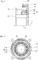
Fig. 2] Fig. 2 is an enlarged cross-sectional view illustrating part of a cross section along the X axis of the cam clutch shown inFig. 1 . - [
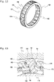
Fig. 3] Fig. 3 is a cross-sectional view of the cam clutch shown inFig. 1 cut along line A-A inFig. 2 . - [
Fig. 4] Fig. 4 is a perspective view illustrating a configuration of a cam in the cam clutch shown inFig. 1 . - [
Fig. 5] Fig. 5 is a perspective view illustrating a configuration of a cam cage in the cam clutch shown inFig. 1 . - [
Fig. 6] Fig. 6 is an illustrative operation diagram of the cam clutch shown inFig. 1 . - [
Fig. 7] Fig. 7 is a lateral cross-sectional view perpendicular to the X axis illustrating part of the configuration of one example of the cam clutch according to a second embodiment of the present invention. - [
Fig. 8] Fig. 8 is a perspective view illustrating a configuration of a cam cage in the cam clutch shown inFig. 7 . - [
Fig. 9] Fig. 9 is a lateral cross-sectional view perpendicular to the X axis illustrating part of the configuration of one example of the cam clutch according to a third embodiment of the present invention. - [
Fig. 10] Fig. 10 is a perspective view illustrating a configuration of a cam cage in the cam clutch shown inFig. 9 . - [
Fig. 11] Fig. 11 is a lateral cross-sectional view perpendicular to the X axis illustrating part of the configuration of one example of the cam clutch according to a fourth embodiment of the present invention. - [
Fig. 12] Fig. 12 is a perspective view illustrating a configuration of a cam cage in the cam clutch shown inFig. 11 . - [
Fig. 13] Fig. 13 is a lateral cross-sectional view perpendicular to the X axis illustrating part of the configuration of one example of the cam clutch according to a fifth embodiment of the present invention. - [
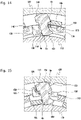
Fig. 14] Fig. 14 is a lateral cross-sectional view perpendicular to the X axis illustrating part of the configuration of one example of the cam clutch according to a sixth embodiment of the present invention. - [
Fig. 15] Fig. 15 is a lateral cross-sectional view perpendicular to the X axis illustrating part of the configuration of one example of the cam clutch according to a seventh embodiment of the present invention. - [
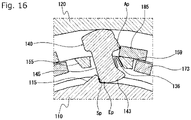
Fig. 16] Fig. 16 is a lateral cross-sectional view perpendicular to the X axis illustrating part of the configuration of one example of the cam clutch according to an eighth embodiment of the present invention. - Embodiments of the present invention are described with reference to
Fig. 1 to Fig. 16 . Note, however, the present invention is not limited to these embodiments. - The
cam clutch 100 according to a first embodiment of the present invention includes aninner race 110 and anouter race 120 that are rotatable relative to each other on the same X axis, and acam mechanism 130 that transmits and interrupts power between theinner race 110 and theouter race 120, as shown inFig. 1 to Fig. 3 . - The
cam mechanism 130 is made up of a plurality ofcams 140 arranged between theinner race 110 and theouter race 120, acam cage 150 holding each of the plurality ofcams 140 on the same circumference at predetermined circumferential intervals, and anannular garter spring 135 that is a biasing means that biases each of the plurality ofcams 140 to make contact with theinner race 110 and theouter race 120. - The
cam 140 includes, as shown inFig. 4 , ahead part 141 having a circumferential surface formed in an arcuate curved shape protruding radially outward and constituting a radiallyouter engagement surface 142 making contact with theouter race 120, aleg part 143 having a circumferential surface formed in an arcuate curved shape protruding radially inward and constituting a radiallyinner engagement surface 144 making contact with theinner race 110, and astrut part 145 connecting thehead part 141 and theleg part 143. Thehead part 141 extends out from thestrut part 145 in the circumferential direction. - The radially
outer engagement surface 142 of thecam 140 is formed with a garterspring mount groove 146 for receiving thegarter spring 135 fitted therein, in a central part in a direction perpendicular to the end face of the cam 140 (X-axis direction). The garterspring mount groove 146 is designed to impart a clockwise (inFig. 3 ) rotational moment to thecam 140 when it is biased by thegarter spring 135 radially inward. - The
cam cage 150 has circumferentially equally spacedpockets 160 as shown inFig. 5 . - This
cam cage 150 includes a pair ofannular plates columnar parts 155 axially extending at circumferentially equally spaced positions and connecting theannular plates columnar parts 155 forming thepockets 160. Oneannular plate 151 is designed to have larger outer dimensions than the otherannular plate 152 so that it is placed in contact with the bottom surface of a recess formed in one end face of theouter race 120. - Each of the
columnar parts 155 protrudes radially outward more than the outer peripheral edge of the otherannular plate 152, and is formed with a circumferentially extending garterspring mount groove 157 in an outer circumferential surface thereof. - The
cams 140 are inserted into thepockets 160 from theleg part 143 side such that thestrut parts 145 are positioned inside thepockets 160, and with thegarter spring 135 mounted, the cams are held on thecam cage 150. With thecams 140 held on thecam cage 150, a corner part on one side of thehead part 141 of thecam 140 abuts on a side face on the other side of thecolumnar part 155. This restricts the circumferential position of thecam 140, as well as the attitude of thecam 140, so that all thecams 140 are brought in contact with theinner race 110 andouter race 120 without variations in their attitude (inclination). - This
cam clutch 100 is provided with acage rotation stopper 170 that is fixed to theouter race 120 and prohibits relative rotation of thecam cage 150 relative to theinner race 110 andouter race 120. - The
cage rotation stopper 170 includes anannular plate part 171 that makes surface contact with oneannular plate 151 of thecam cage 150 and restricts axial movements of thecam mechanism 130, acircumferential wall part 172 fitted over theouter race 120 and axially extending from an outer peripheral edge on one side of theannular plate part 171, and a plurality ofstopper parts 173 axially extending at an inner peripheral edge of theannular plate part 171 to be inserted intogrooves 156 formed in the correspondingcolumnar parts 155 of thecam cage 150. Anengaging pawl 174 is formed on thecircumferential wall part 172, to make sliding engagement with an axially extendingrecessed groove 121 formed on the outer circumferential surface of theouter race 120. - The
cam clutch 100 according to this embodiment is provided with an operating mode switch means 180 for switching between a free state that allows relative rotation between theinner race 110 andouter race 120 and a locked state that prohibits relative rotation between theinner race 110 andouter race 120. - The operating mode switch means 180 of this embodiment includes an annular plate-like
end wall part 181, a plurality oftab members 185 axially extending from an inner peripheral edge on one side of theend wall part 181 and functioning as a cam attitude change part, and acircumferential wall part 182 axially extending from an outer peripheral edge on one side of theend wall part 181. The operating mode switch means 180 is provided such that itscircumferential wall part 182 is fitted over thecircumferential wall part 172 of thecage rotation stopper 170 via acylindrical bearing member 190, and the plurality oftab members 185 are located close to the outer circumferential surface of theinner race 110 between theleg parts 143 ofadjacent cams 140. - Hereinafter, the operation of the
cam clutch 100 according to the above first embodiment will be described. - The
cam clutch 100 is in the one-way lock mode in which rotation of theouter race 120 relative to theinner race 110 in the forward direction (clockwise inFig. 3 ) is prohibited when thetab members 185 constituting the cam attitude change part of thiscam clutch 100 are at the neutral position, and can be switched from the one-way lock mode to the two-way free mode in which theouter race 120 is allowed to rotate relative to theinner race 110 in forward and reverse directions by operation of the operating mode switch means 180. - Namely, when the operating mode switch means 180 is rotated in the forward direction, each of the plurality of
tab members 185 moves circumferentially in the forward direction relative to thecams 140, which causes thecams 140 to tilt around a load support point as the center of rotation in a direction in which they are disengaged from theinner race 110 andouter race 120. In thiscam clutch 100, thehead parts 141 of thecams 140 abut on thecolumnar parts 155 of thecam cage 150 such that, as shown inFig. 6 , the load support point Sp is located radially between a load application point Ap of thetab member 185 on thecam 140 and a distal contact point Ep between the cam and theouter race 120, or a contact point between the cam and a raceway positioned on the radially distal side relative to the load application point Ap on thecam 140. The radial distance d1 between the load application point Ap and the load support point Sp is larger than the radial distance d2 between the load support point Sp and the distal contact point Ep. Such a configuration allows the distance between the load application point Ap and the load support point Sp to be sufficiently large, and increases the moment that acts on thecams 140 when thetab members 185 move, meaning that the attitude of thecams 140 can be changed with a smaller force and with less influence of production variations of components. Since all thecams 140 are in contact with theinner race 110 andouter race 120 without variations in their attitude (inclination), behavioral variations of thecams 140 can be avoided. The stability of clutch operations can thus be improved and high responsiveness can be achieved. -
Fig. 7 is a lateral cross-sectional view perpendicular to the X axis illustrating part of the configuration of one example of the cam clutch according to a second embodiment of the present invention. - This cam clutch has a configuration similar to the
cam clutch 100 according to the first embodiment except that the operating mode switch means 180 is designed to have thetab members 185 as the cam attitude change part positioned between thehead parts 141 ofadjacent cams 140, while thecam cage 150 abuts on theleg parts 143 of thecams 140 to form the load support points Sp. - The
cam cage 150 includes, as shown inFig. 8 , a pair ofannular plates columnar parts 155 axially extending at circumferentially equally spaced positions and connecting theannular plates plates 159 provided at the outer peripheral edge in the circumferential middle position between adjacentcolumnar parts 155 and connecting theannular plates columnar parts 155 is provided, at one radially inner end thereof, with a protrudedportion 158 protruding in one circumferential direction. The spaces between thecolumnar parts 155 and the connectingplates 159 positioned on the side where thecolumnar parts 155 have their protrudedportions 158 form thepockets 160. - One
annular plate 151 is formed withnotches 153 that are in communication with the spaces formed between thepockets 160, for receiving thestopper parts 173 of thecage rotation stopper 170 inserted thereto. - In the cam clutch according to the above second embodiment, when the operating mode switch means 180 is rotated in the reverse direction (e.g., counterclockwise in
Fig. 7 ), for example, each of the plurality oftab members 185 moves circumferentially in the reverse direction relative to thecams 140, which causes thecams 140 to tilt around the load support points Sp as the center of rotation in a direction in which they are disengaged from theinner race 110 andouter race 120. Since the distance between the load application point Ap and the load support point Sp is sufficiently large, the moment that acts on thecams 140 when thetab members 185 move is larger, meaning that the attitude of thecams 140 can be changed with a smaller force and with less influence of production variations of components. Since all thecams 140 are in contact with theinner race 110 andouter race 120 without variations in their attitude (inclination), behavioral variations of thecams 140 can be avoided. The stability of clutch operations can thus be improved and high responsiveness can be achieved. - In the
cam clutch 100 according to the first embodiment, the cams are biased by thegarter spring 135 and the corner part on one side of thehead part 141 of thecam 140 abuts on the other side face of thecolumnar part 155, which restricts the circumferential position of thecam 140, as well as the attitude of thecam 140. In the cam clutch according to the second embodiment, the cams are biased by thegarter spring 135 such that theleg parts 143 of thecams 140 on the other side abut on the protrudedportions 158 of thecolumnar parts 155, to restrict the circumferential positions of thecams 140, as well as the attitude of thecams 140. Alternatively, a position restricting part that restricts the circumferential positions of thecams 140 and the attitude of thecams 140 may be separately provided. -
Fig. 9 is a lateral cross-sectional view perpendicular to the X axis illustrating part of the configuration of one example of the cam clutch according to a third embodiment of the present invention. - This cam clutch has a configuration similar to the
cam clutch 100 according to the first embodiment except thatposition restricting parts 125 are provided on the inner circumferential surface of theouter race 120, which is the raceway positioned on the radially distal side relative to thetab members 185 that form the cam attitude change part. - The
position restricting parts 125 are provided on the inner circumferential surface of theouter race 120 at circumferentially equally spaced positions such as to protrude radially inward. The position restricting parts need not be formed integrally with theouter race 120 and may be separately formed parts that are fixed to theouter race 120. - The
cam cage 150 includes, as shown inFig. 10 , a pair ofannular plates columnar parts 155 axially extending at circumferentially equally spaced positions and connecting theannular plates annular plate 151 is designed to have larger outer dimensions than the otherannular plate 152 so that it is placed in contact with the bottom surface of a recess formed in one end face of theouter race 120. Thecolumnar parts 155 are continuous with the inner edge of oneannular plate 151 at one end, and continuous with the outer edge of the otherannular plate 152 at the other end. - In this
cam cage 150, the spaces between adjacentcolumnar parts 155 form, circumferentially alternately, pockets 160 in which thecams 140 are disposed andstopper accommodating parts 161 in which thestopper parts 173 of thecage rotation stopper 170 are positioned. - In this cam clutch, the
cams 140 are biased by thegarter spring 135 and one side face of thehead parts 141 of thecams 140 abuts on theposition restricting parts 125 such that the load support point Sp is located radially between a load application point Ap of thetab member 185 on thecam 140 and a distal contact point Ep between the cam and theouter race 120, or a contact point between the cam and a raceway positioned on the radially distal side relative to the load application point Ap on thecam 140. The load support point Sp is located at such a radial position that the radial distance between the load application point Ap and the load support point Sp is larger than the radial distance between the load support point Sp and the distal contact point Ep. - In this cam clutch, when the operating mode switch means 180 is rotated in the forward direction (e.g., clockwise in
Fig. 9 ), each of the plurality oftab members 185 moves circumferentially in the forward direction relative to thecams 140, which causes thecams 140 to tilt around the load support points Sp as the center of rotation in a direction in which they are disengaged from theinner race 110 andouter race 120. Since the distance between the load application point Ap and the load support point Sp is sufficiently large, the moment that acts on thecams 140 when thetab members 185 move is larger, meaning that the attitude of thecams 140 can be changed with a smaller force and with less influence of production variations of components. Since theposition restricting parts 125 keep all thecams 140 in contact with theinner race 110 andouter race 120 without variations in their attitude (inclination), behavioral variations of thecams 140 can be avoided. The stability of clutch operations can thus be improved and high responsiveness can be achieved. - In the case where the operating mode switch means 180 is designed to have the
tab members 185 as the cam attitude change part positioned between thehead parts 141 ofadjacent cams 140, the position restricting parts may be formed on the outer circumferential surface of the inner race. -
Fig. 11 is a lateral cross-sectional view perpendicular to the X axis illustrating part of the configuration of one example of the cam clutch according to a fourth embodiment of the present invention. - This cam clutch has a basic configuration similar to the cam clutch according to the second embodiment except that
position restricting parts 115 are provided on the outer circumferential surface of theinner race 110, which is the raceway positioned on the radially distal side relative to thetab members 185 that form the cam attitude change part. - The
position restricting parts 115 are provided on the outer circumferential surface of theinner race 110 at circumferentially equally spaced positions such as to protrude radially outward. The position restricting parts need not be formed integrally with theinner race 110 and may be separately formed parts that are fixed to theinner race 110. - The
cam cage 150 includes, as shown inFig. 12 , a pair ofannular plates columnar parts 155 axially extending at circumferentially equally spaced positions and connecting theannular plates - In this
cam cage 150, the spaces between adjacentcolumnar parts 155 form, circumferentially alternately, pockets 160 in which thecams 140 are disposed andstopper accommodating parts 161 in which thestopper parts 173 of thecage rotation stopper 170 are positioned. - In this cam clutch, the
cams 140 are biased by thegarter spring 135 and the other side face of theleg parts 143 of thecams 140 abuts on theposition restricting parts 115 such that the load support point Sp is located radially between a load application point Ap of thetab member 185 on thecam 140 and a distal contact point Ep between the cam and theinner race 110, or a contact point between the cam and a raceway positioned on the radially distal side relative to the load application point Ap on thecam 140. The load support point Sp is located at such a radial position that the radial distance between the load application point Ap and the load support point Sp is larger than the radial distance between the load support point Sp and the distal contact point Ep. - In this cam clutch, when the operating mode switch means 180 is rotated in the reverse direction (e.g., counterclockwise in
Fig. 11 ), each of the plurality oftab members 185 moves circumferentially in the reverse direction relative to thecams 140, which causes thecams 140 to tilt around the load support points Sp as the center of rotation in a direction in which they are disengaged from theinner race 110 andouter race 120. Since the distance between the load application point Ap and the load support point Sp is sufficiently large, the moment that acts on thecams 140 when thetab members 185 move is larger, meaning that the attitude of thecams 140 can be changed with a smaller force and with less influence of production variations of components. Since the plate springs as the position restricting means act to keep all thecams 140 in contact with theinner race 110 andouter race 120 without variations in their attitude (inclination), behavioral variations of thecams 140 can be avoided. The stability of clutch operations can thus be improved and high responsiveness can be achieved. - While a garter spring is used as the biasing means to bias the cams radially inward in the configurations described above, the cam clutch of the present invention may be configured such that the cams are biased radially outward by a biasing means, or such that the cams are biased in a circumferential direction.
-
Fig. 13 is a lateral cross-sectional view perpendicular to the X axis illustrating part of the configuration of one example of the cam clutch according to a fifth embodiment of the present invention. - This cam clutch has a basic configuration similar to the
cam clutch 100 according to the first embodiment except that plate springs 136 are used instead of the garter spring as the biasing means for biasing thecams 140 in a circumferential direction. - The plate springs 136 are each provided between one side face of the
columnar parts 155 of thecam cage 150 and the other side face of thehead parts 141 of thecams 140 so as to impart a clockwise (inFig. 13 ) rotational moment to thecams 140 and also to function as position restricting means that restrict the circumferential positions of thecams 140 and the attitude of thecams 140. - In this cam clutch, the
cams 140 are circumferentially biased by the plate springs 136 and a corner part of thehead part 141 of thecam 140 on one side abuts on the other side face of thecolumnar part 155 such that the load support point Sp is located radially between a load application point Ap of thetab member 185 on thecam 140 and a distal contact point Ep between the cam and theouter race 120, or a contact point between the cam and a raceway positioned on the radially distal side relative to the load application point Ap on thecam 140. The load support point Sp is located at such a radial position that the radial distance between the load application point Ap and the load support point Sp is larger than the radial distance between the load support point Sp and the distal contact point Ep. - In this cam clutch, when the operating mode switch means 180 is rotated in the forward direction (clockwise in
Fig. 13 ), each of the plurality oftab members 185 moves circumferentially in the forward direction relative to thecams 140, which causes thecams 140 to tilt around the load support points Sp as the center of rotation in a direction in which they are disengaged from theinner race 110 andouter race 120. Since the distance between the load application point Ap and the load support point Sp is sufficiently large, the moment that acts on thecams 140 when thetab members 185 move is larger, meaning that the attitude of thecams 140 can be changed with a smaller force and with less influence of production variations of components. Since the plate springs 136 as the position restricting means act to keep all thecams 140 in contact with theinner race 110 andouter race 120 without variations in their attitude (inclination), behavioral variations of thecams 140 can be avoided. The stability of clutch operations can thus be improved and high responsiveness can be achieved. - The cam clutch according to the above second embodiment, the cam clutch according to the above third embodiment, and the cam clutch according to the above fourth embodiment may also be configured to use plate springs as biasing means for biasing the
cams 140 circumferentially instead of the garter spring. -
Fig. 14 is a lateral cross-sectional view perpendicular to the X axis illustrating part of the configuration of one example of the cam clutch according to a sixth embodiment of the present invention. - This cam clutch has a basic configuration similar to the cam clutch according to the above second embodiment except that plate springs are used instead of the garter spring as the biasing means for biasing the
cams 140 in a circumferential direction. - The plate springs 136 are each provided inside the pockets of the
cam cage 150 between one side face of thestrut parts 145 of thecams 140 and the other side face of the connectingplates 159 so as to impart a clockwise (inFig. 14 ) rotational moment to thecams 140 and also to function as position restricting means that cause the other side face of theleg parts 143 of thecams 140 to abut on the protrudedportions 158 of thecolumnar parts 155 of thecam cage 150 for restricting the circumferential positions of thecams 140 and the attitude of thecams 140. -
Fig. 15 is a lateral cross-sectional view perpendicular to the X axis illustrating part of the configuration of one example of the cam clutch according to a seventh embodiment of the present invention. - This cam clutch has a basic configuration similar to the cam clutch according to the above third embodiment except that plate springs are used instead of the garter spring as the biasing means for biasing the
cams 140 in a circumferential direction, and that the cam cage has a different configuration. - The
cam cage 150 has a configuration similar to thecam cage 150 of the cam clutch according to the third embodiment except that thecolumnar parts 155 positioned circumferentially on the other side of the pockets have a protrudedportion 158 that is formed such as to protrude radially outward from an outer peripheral edge of the other annular plate. - The plate springs 136 are each provided between one side face of the protruded
portions 158 of thecolumnar parts 155 of thecam cage 150 and the other side face of thehead parts 141 of thecams 140 so as to impart a clockwise (inFig. 15 ) rotational moment to thecams 140 and also to function as position restricting means that cause one side face of thehead parts 141 of thecams 140 to abut on theposition restricting parts 125 formed on theouter race 120 for restricting the circumferential positions of thecams 140 and the attitude of thecams 140. -
Fig. 16 is a lateral cross-sectional view perpendicular to the X axis illustrating part of the configuration of one example of the cam clutch according to an eighth embodiment of the present invention. - This cam clutch has a basic configuration similar to the cam clutch according to the above fourth embodiment except that plate springs are used instead of the garter spring as the biasing means for biasing the
cams 140 in a circumferential direction. - The plate springs 136 are each provided inside the pockets of the
cam cage 150 between one side face of thestrut parts 145 of thecams 140 and the other side face of the connectingplates 159 so as to impart a clockwise (inFig. 16 ) rotational moment to thecams 140 and also to function as position restricting means that cause one side face of theleg parts 143 of thecams 140 to abut on theposition restricting parts 115 formed on theinner race 110 for restricting the circumferential positions of thecams 140 and the attitude of thecams 140. - In the cam clutch according to the sixth embodiment and in the cam clutch according to the eighth embodiment, when the operating mode switch means 180 is rotated in the reverse direction, each of the plurality of
tab members 185 moves circumferentially in the reverse direction relative to thecams 140, which causes thecams 140 to tilt around the load support points Sp as the center of rotation in a direction in which they are disengaged from theinner race 110 andouter race 120. In the cam clutch according to the seventh embodiment, when the operating mode switch means 180 is rotated in the forward direction, each of the plurality oftab members 185 moves circumferentially in the forward direction relative to thecams 140, which causes thecams 140 to tilt around the load support points Sp as the center of rotation in a direction in which they are disengaged from theinner race 110 andouter race 120. - Since the distance between the load application point Ap and the load support point Sp is sufficiently large, the moment that acts on the
cams 140 when thetab members 185 move is larger, meaning that the attitude of thecams 140 can be changed with a smaller force and with less influence of production variations of components. Since the plate springs 136 as the position restricting means act to keep all thecams 140 in contact with theinner race 110 andouter race 120 without variations in their attitude (inclination), behavioral variations of thecams 140 can be avoided. The stability of clutch operations can thus be improved and high responsiveness can be achieved. - While embodiments of the present invention have been described above in detail, the present invention is not limited to the embodiments described above. Various design changes may be made without departing from the scope of the present invention set forth in the claims.
- The above embodiments featured configurations in which the cams are biased by the biasing means to make contact with the inner race and outer race and tilted by the operating mode switch means to disengage from the inner race and outer race. Alternatively, the cams may be biased by the biasing means to separate from the inner race or outer race and tilted by the operating mode switch means to engage with the inner race and outer race.
- The cams forming the cam mechanism may be designed to make frictional engagement with the inner race and outer race when rotated to either of the forward direction and reverse direction.
- Moreover, while the operating mode switch means described in the above embodiments is configured to move the cam attitude change part circumferentially independently of rotation of the inner race and outer race, the operating mode switch means may be configured to move the cam attitude change part radially or axially independently of rotation of the inner race and outer race.
- The cam cage and the cage rotation stopper may be integrally formed.
- The above embodiments featured configurations provided with a cam mechanism with a plurality of identical cams circumferentially arranged on the same circumference and imparted with a rotational moment in the same direction by the biasing means. Alternatively, the cam mechanism may be designed to include a first cam and a second cam imparted with a rotational moment in different directions by the biasing means. In such a design, the first cam would be configured to make frictional engagement with the inner race and outer race when the outer race rotates in one direction, for example, and be tilted in a direction in which it cancels the frictional engagement with the inner race and outer race when the outer race rotates in the other direction. The second cam would be configured to make frictional engagement with the inner race and outer race when the outer race rotates in the other direction, for example, and be tilted in a direction in which it cancels the frictional engagement with the inner race and outer race when the outer race rotates in one direction.
- The arrangement of the first cams and second cams is not limited to a particular layout. The first cams and second cams may be aligned on the same circumference, or a plurality of rows of a plurality of cams circumferentially aligned on the same circumference may be arranged side by side in the axial direction. In a configuration provided with a plurality of rows of cams, each row of cams may include only one of the first cam and second cam, or may include both of the first cam and second cam. The numbers of the first cams and second cams may be the same, or different.
- In a case where the first cams and second cams are aligned on the same circumference, the first cams and second cams may be circumferentially alternately arranged, or the first and second cams may not be alternately arranged.
- The operating mode switch means may be configured to be able to change the attitude of the first cam and the attitude of the second cam simultaneously, or to change the attitude of the first cam and the attitude of the second cam independently.
- Alternatively, the attitudes of the first cam and the second cam may be changed by different operating mode switch means. In this case, for example, the operating mode switch means is provided on both sides in the axial direction of the cam mechanism, one operating mode switch means being configured to change the attitude of the first cams, and another operating mode switch means being configured to change the attitude of the second cams. The cam clutch with such a configuration can switch among four operating modes, two-way lock mode, forward direction lock mode, reverse direction lock mode, and two-way free mode.
- One operating mode switch means and the other operating mode switch means may either have the same configuration, or different configurations. That is, in a case where one operating mode switch means is configured to move the cam attitude change part circumferentially, for example, the other operating mode switch means may either be configured to move the cam attitude change part circumferentially, or radially or axially. The same applies to cases where one operating mode switch means is configured to move the cam attitude change part radially or axially.
-
- 100
- Cam clutch
- 110
- Inner race
- 115
- Position restricting part
- 120
- Outer race
- 121
- Recessed groove
- 125
- Position restricting part
- 130
- Cam mechanism
- 135
- Garter spring
- 136
- Plate spring
- 140
- Cam
- 141
- Head part
- 142
- Radially outer engagement surface
- 143
- Leg part
- 144
- Radially inner engagement surface
- 145
- Strut part
- 146
- Garter spring mount groove
- 150
- Cam cage
- 151
- Annular plate
- 152
- Annular plate
- 153
- Notch
- 155
- Columnar part
- 156
- Groove
- 157
- Garter spring mount groove
- 158
- Protruded portion
- 159
- Connecting plate
- 160
- 161
- Stopper accommodating part
- 170
- Cage rotation stopper
- 171
- Annular plate part
- 172
- Circumferential wall part
- 173
- Stopper part
- 174
- Engaging pawl
- 180
- Operating mode switch means
- 181
- End wall part
- 182
- Circumferential wall part
- 185
- Tab member
- 190
- Bearing member
- Ap
- Load application point
- Ep
- Distal contact point
- Sp
- Load support point
Claims (5)
- A cam clutch comprising: an inner race and an outer race that are coaxial and rotatable relative to each other; a plurality of cams circumferentially arranged at intervals between the inner race and the outer race; a biasing means biasing each of the plurality of cams so that each of the plurality of cams makes contact with the inner race and the outer race; andan operating mode switch means including a cam attitude change part that is drivable independently of rotation of the inner race and the outer race to forcibly tilt the cams, whereina load support point is located radially between a load application point of the cam attitude change part on the cam and a distal contact point of the cam on a raceway that is one of the inner race and the outer race positioned on a radially distal side relative to the load application point, a radial distance between the load application point and the load support point being larger than a radial distance between the load support point and the distal contact point.
- The cam clutch according to claim 1, further comprising a position restricting part that restricts a circumferential position and an attitude of each of the plurality of cams.
- The cam clutch according to claim 2, wherein the position restricting part is formed on a raceway positioned on a radially distal side relative to the load application point.
- The cam clutch according to any one of claims 1 to 3, wherein the plurality of cams include a first cam and a second cam imparted with a moment in different directions by the biasing means,
the operating mode switch means being configured to be able to change an attitude of the first cam and an attitude of the second cam independently. - The cam clutch according to claim 4, further comprising a first operating mode switch means that changes the attitude of the first cam and a second operating mode switch means that changes the attitude of the second cam.
Applications Claiming Priority (2)
| Application Number | Priority Date | Filing Date | Title |
|---|---|---|---|
| JP2019094347A JP6882699B2 (en) | 2019-05-20 | 2019-05-20 | Cam clutch |
| PCT/JP2020/018667 WO2020235358A1 (en) | 2019-05-20 | 2020-05-08 | Cam clutch |
Publications (3)
| Publication Number | Publication Date |
|---|---|
| EP3974674A1 true EP3974674A1 (en) | 2022-03-30 |
| EP3974674A4 EP3974674A4 (en) | 2023-05-24 |
| EP3974674B1 EP3974674B1 (en) | 2024-09-18 |
Family
ID=82399626
Family Applications (1)
| Application Number | Title | Priority Date | Filing Date |
|---|---|---|---|
| EP20810038.8A Active EP3974674B1 (en) | 2019-05-20 | 2020-05-08 | Cam clutch |
Country Status (5)
| Country | Link |
|---|---|
| US (1) | US11808313B2 (en) |
| EP (1) | EP3974674B1 (en) |
| KR (1) | KR102667993B1 (en) |
| CN (1) | CN113840988A (en) |
| WO (1) | WO2020235358A1 (en) |
Families Citing this family (5)
| Publication number | Priority date | Publication date | Assignee | Title |
|---|---|---|---|---|
| JP7598023B2 (en) | 2021-06-08 | 2024-12-11 | 株式会社椿本チエイン | Cam clutch |
| JP7227515B2 (en) * | 2021-06-29 | 2023-02-22 | 株式会社椿本チエイン | cam clutch |
| JP7636675B2 (en) * | 2021-10-27 | 2025-02-27 | 株式会社椿本チエイン | Cam clutch |
| JP7709064B2 (en) * | 2023-07-11 | 2025-07-16 | 株式会社椿本チエイン | Cam clutch unit |
| JP2026029162A (en) * | 2024-08-08 | 2026-02-20 | 株式会社椿本チエイン | Cam clutch |
Family Cites Families (19)
| Publication number | Priority date | Publication date | Assignee | Title |
|---|---|---|---|---|
| US2721638A (en) * | 1953-01-08 | 1955-10-25 | Borg Warner | One-way clutch |
| US2973072A (en) * | 1956-06-18 | 1961-02-28 | Borg Warner | One-way clutch |
| SE450282B (en) | 1985-08-30 | 1987-06-15 | Skf Nova Ab | DOUBLE-OPENING WHEELS |
| JP3698743B2 (en) * | 1994-06-29 | 2005-09-21 | Ntn株式会社 | Rotation transmission device |
| JP2939134B2 (en) | 1994-08-03 | 1999-08-25 | 株式会社フジユニバンス | One-way clutch |
| JPH10323257A (en) * | 1997-03-24 | 1998-12-08 | Ntn Corp | Clutch device for seat, and seat back inclination adjusting device |
| JP3895024B2 (en) | 1997-12-24 | 2007-03-22 | Ntn株式会社 | 2-way simultaneous idle / lock switching clutch |
| CN2809322Y (en) * | 2005-01-21 | 2006-08-23 | 厦门恒耀金属有限公司 | Non-contact cam one-way clutch |
| JP2008075867A (en) | 2006-08-21 | 2008-04-03 | Ntn Corp | One-way clutch unit |
| DE102007015104A1 (en) * | 2007-03-29 | 2008-10-02 | Borg Warner Inc., Auburn Hills | Clutch device for transmitting torque between engine output shaft and clutch input shaft, has free-wheel arrangement with free-wheels that have inner and outer rings formed of one-piece with shafts |
| WO2008154830A1 (en) | 2007-06-19 | 2008-12-24 | Byd Company Limited | Tri-state overrunning clutch |
| JP5876410B2 (en) | 2010-02-17 | 2016-03-02 | 株式会社ユニバンス | Power transmission device |
| JP5282761B2 (en) | 2010-04-14 | 2013-09-04 | トヨタ自動車株式会社 | Two-way clutch and vehicle drive device |
| JP5735754B2 (en) | 2010-04-26 | 2015-06-17 | 株式会社ユニバンス | Power transmission device |
| EP2607735B1 (en) * | 2010-08-26 | 2015-03-18 | Univance Corporation | Power transmission device |
| WO2012026019A1 (en) | 2010-08-26 | 2012-03-01 | 株式会社ユニバンス | Clutch device |
| EP2705269A1 (en) | 2011-05-06 | 2014-03-12 | Aktiebolaget SKF | Pulley unit for bi-directional torque transfer |
| CN105830625B (en) * | 2015-01-30 | 2020-08-18 | 德昌电机(深圳)有限公司 | Mower and clutch thereof |
| CN110701210B (en) | 2019-10-23 | 2024-12-03 | 中南大学 | Controllable sprag clutch and its applied bidirectional overrunning clutch |
-
2020
- 2020-05-08 EP EP20810038.8A patent/EP3974674B1/en active Active
- 2020-05-08 WO PCT/JP2020/018667 patent/WO2020235358A1/en not_active Ceased
- 2020-05-08 KR KR1020217039406A patent/KR102667993B1/en active Active
- 2020-05-08 CN CN202080033896.7A patent/CN113840988A/en active Pending
-
2021
- 2021-11-05 US US17/520,434 patent/US11808313B2/en active Active
Also Published As
| Publication number | Publication date |
|---|---|
| KR20220008844A (en) | 2022-01-21 |
| EP3974674A4 (en) | 2023-05-24 |
| WO2020235358A1 (en) | 2020-11-26 |
| US20220056965A1 (en) | 2022-02-24 |
| KR102667993B1 (en) | 2024-05-23 |
| US11808313B2 (en) | 2023-11-07 |
| CN113840988A (en) | 2021-12-24 |
| EP3974674B1 (en) | 2024-09-18 |
Similar Documents
| Publication | Publication Date | Title |
|---|---|---|
| US11808313B2 (en) | Cam clutch | |
| EP3974673A1 (en) | Cam clutch | |
| US11761495B2 (en) | Cam clutch | |
| US11661979B2 (en) | Dog clutch with ratcheting one-way clutch | |
| WO2020159937A1 (en) | Four mode switchable one way clutch | |
| US12253121B2 (en) | Cam clutch | |
| US11365771B2 (en) | One-way clutch | |
| JP2021177091A (en) | Cam clutch | |
| US12442423B2 (en) | Cam clutch | |
| US12366269B2 (en) | Cam clutch | |
| US11802595B2 (en) | Cam clutch | |
| EP4265933A1 (en) | Cam clutch | |
| US12253122B2 (en) | Selectable clutch | |
| US12253123B1 (en) | Cam clutch | |
| JP7417155B1 (en) | cam clutch | |
| EP4382761B1 (en) | Clutch device | |
| JP2016169847A (en) | Constant velocity joint |
Legal Events
| Date | Code | Title | Description |
|---|---|---|---|
| STAA | Information on the status of an ep patent application or granted ep patent |
Free format text: STATUS: THE INTERNATIONAL PUBLICATION HAS BEEN MADE |
|
| PUAI | Public reference made under article 153(3) epc to a published international application that has entered the european phase |
Free format text: ORIGINAL CODE: 0009012 |
|
| STAA | Information on the status of an ep patent application or granted ep patent |
Free format text: STATUS: REQUEST FOR EXAMINATION WAS MADE |
|
| 17P | Request for examination filed |
Effective date: 20211207 |
|
| AK | Designated contracting states |
Kind code of ref document: A1 Designated state(s): AL AT BE BG CH CY CZ DE DK EE ES FI FR GB GR HR HU IE IS IT LI LT LU LV MC MK MT NL NO PL PT RO RS SE SI SK SM TR |
|
| DAV | Request for validation of the european patent (deleted) | ||
| DAX | Request for extension of the european patent (deleted) | ||
| A4 | Supplementary search report drawn up and despatched |
Effective date: 20230424 |
|
| RIC1 | Information provided on ipc code assigned before grant |
Ipc: F16D 41/08 20060101AFI20230418BHEP |
|
| REG | Reference to a national code |
Ref country code: DE Ref legal event code: R079 Ipc: F16D0041069000 Ref country code: DE Ref legal event code: R079 Ref document number: 602020038035 Country of ref document: DE Free format text: PREVIOUS MAIN CLASS: F16D0041080000 Ipc: F16D0041069000 |
|
| GRAP | Despatch of communication of intention to grant a patent |
Free format text: ORIGINAL CODE: EPIDOSNIGR1 |
|
| STAA | Information on the status of an ep patent application or granted ep patent |
Free format text: STATUS: GRANT OF PATENT IS INTENDED |
|
| RIC1 | Information provided on ipc code assigned before grant |
Ipc: F16D 41/07 20060101ALI20240409BHEP Ipc: F16D 41/069 20060101AFI20240409BHEP |
|
| INTG | Intention to grant announced |
Effective date: 20240513 |
|
| GRAS | Grant fee paid |
Free format text: ORIGINAL CODE: EPIDOSNIGR3 |
|
| GRAA | (expected) grant |
Free format text: ORIGINAL CODE: 0009210 |
|
| STAA | Information on the status of an ep patent application or granted ep patent |
Free format text: STATUS: THE PATENT HAS BEEN GRANTED |
|
| AK | Designated contracting states |
Kind code of ref document: B1 Designated state(s): AL AT BE BG CH CY CZ DE DK EE ES FI FR GB GR HR HU IE IS IT LI LT LU LV MC MK MT NL NO PL PT RO RS SE SI SK SM TR |
|
| REG | Reference to a national code |
Ref country code: GB Ref legal event code: FG4D |
|
| REG | Reference to a national code |
Ref country code: CH Ref legal event code: EP |
|
| REG | Reference to a national code |
Ref country code: IE Ref legal event code: FG4D |
|
| REG | Reference to a national code |
Ref country code: DE Ref legal event code: R096 Ref document number: 602020038035 Country of ref document: DE |
|
| REG | Reference to a national code |
Ref country code: LT Ref legal event code: MG9D |
|
| PG25 | Lapsed in a contracting state [announced via postgrant information from national office to epo] |
Ref country code: NO Free format text: LAPSE BECAUSE OF FAILURE TO SUBMIT A TRANSLATION OF THE DESCRIPTION OR TO PAY THE FEE WITHIN THE PRESCRIBED TIME-LIMIT Effective date: 20241218 |
|
| PG25 | Lapsed in a contracting state [announced via postgrant information from national office to epo] |
Ref country code: GR Free format text: LAPSE BECAUSE OF FAILURE TO SUBMIT A TRANSLATION OF THE DESCRIPTION OR TO PAY THE FEE WITHIN THE PRESCRIBED TIME-LIMIT Effective date: 20241219 Ref country code: FI Free format text: LAPSE BECAUSE OF FAILURE TO SUBMIT A TRANSLATION OF THE DESCRIPTION OR TO PAY THE FEE WITHIN THE PRESCRIBED TIME-LIMIT Effective date: 20240918 |
|
| PG25 | Lapsed in a contracting state [announced via postgrant information from national office to epo] |
Ref country code: BG Free format text: LAPSE BECAUSE OF FAILURE TO SUBMIT A TRANSLATION OF THE DESCRIPTION OR TO PAY THE FEE WITHIN THE PRESCRIBED TIME-LIMIT Effective date: 20240918 |
|
| PG25 | Lapsed in a contracting state [announced via postgrant information from national office to epo] |
Ref country code: LV Free format text: LAPSE BECAUSE OF FAILURE TO SUBMIT A TRANSLATION OF THE DESCRIPTION OR TO PAY THE FEE WITHIN THE PRESCRIBED TIME-LIMIT Effective date: 20240918 |
|
| PG25 | Lapsed in a contracting state [announced via postgrant information from national office to epo] |
Ref country code: HR Free format text: LAPSE BECAUSE OF FAILURE TO SUBMIT A TRANSLATION OF THE DESCRIPTION OR TO PAY THE FEE WITHIN THE PRESCRIBED TIME-LIMIT Effective date: 20240918 |
|
| REG | Reference to a national code |
Ref country code: NL Ref legal event code: MP Effective date: 20240918 |
|
| PG25 | Lapsed in a contracting state [announced via postgrant information from national office to epo] |
Ref country code: RS Free format text: LAPSE BECAUSE OF FAILURE TO SUBMIT A TRANSLATION OF THE DESCRIPTION OR TO PAY THE FEE WITHIN THE PRESCRIBED TIME-LIMIT Effective date: 20241218 |
|
| PG25 | Lapsed in a contracting state [announced via postgrant information from national office to epo] |
Ref country code: RS Free format text: LAPSE BECAUSE OF FAILURE TO SUBMIT A TRANSLATION OF THE DESCRIPTION OR TO PAY THE FEE WITHIN THE PRESCRIBED TIME-LIMIT Effective date: 20241218 Ref country code: NO Free format text: LAPSE BECAUSE OF FAILURE TO SUBMIT A TRANSLATION OF THE DESCRIPTION OR TO PAY THE FEE WITHIN THE PRESCRIBED TIME-LIMIT Effective date: 20241218 Ref country code: LV Free format text: LAPSE BECAUSE OF FAILURE TO SUBMIT A TRANSLATION OF THE DESCRIPTION OR TO PAY THE FEE WITHIN THE PRESCRIBED TIME-LIMIT Effective date: 20240918 Ref country code: HR Free format text: LAPSE BECAUSE OF FAILURE TO SUBMIT A TRANSLATION OF THE DESCRIPTION OR TO PAY THE FEE WITHIN THE PRESCRIBED TIME-LIMIT Effective date: 20240918 Ref country code: GR Free format text: LAPSE BECAUSE OF FAILURE TO SUBMIT A TRANSLATION OF THE DESCRIPTION OR TO PAY THE FEE WITHIN THE PRESCRIBED TIME-LIMIT Effective date: 20241219 Ref country code: FI Free format text: LAPSE BECAUSE OF FAILURE TO SUBMIT A TRANSLATION OF THE DESCRIPTION OR TO PAY THE FEE WITHIN THE PRESCRIBED TIME-LIMIT Effective date: 20240918 Ref country code: BG Free format text: LAPSE BECAUSE OF FAILURE TO SUBMIT A TRANSLATION OF THE DESCRIPTION OR TO PAY THE FEE WITHIN THE PRESCRIBED TIME-LIMIT Effective date: 20240918 |
|
| REG | Reference to a national code |
Ref country code: AT Ref legal event code: MK05 Ref document number: 1724924 Country of ref document: AT Kind code of ref document: T Effective date: 20240918 |
|
| PG25 | Lapsed in a contracting state [announced via postgrant information from national office to epo] |
Ref country code: NL Free format text: LAPSE BECAUSE OF FAILURE TO SUBMIT A TRANSLATION OF THE DESCRIPTION OR TO PAY THE FEE WITHIN THE PRESCRIBED TIME-LIMIT Effective date: 20240918 |
|
| PG25 | Lapsed in a contracting state [announced via postgrant information from national office to epo] |
Ref country code: IS Free format text: LAPSE BECAUSE OF FAILURE TO SUBMIT A TRANSLATION OF THE DESCRIPTION OR TO PAY THE FEE WITHIN THE PRESCRIBED TIME-LIMIT Effective date: 20250118 Ref country code: PT Free format text: LAPSE BECAUSE OF FAILURE TO SUBMIT A TRANSLATION OF THE DESCRIPTION OR TO PAY THE FEE WITHIN THE PRESCRIBED TIME-LIMIT Effective date: 20250120 |
|
| PG25 | Lapsed in a contracting state [announced via postgrant information from national office to epo] |
Ref country code: RO Free format text: LAPSE BECAUSE OF FAILURE TO SUBMIT A TRANSLATION OF THE DESCRIPTION OR TO PAY THE FEE WITHIN THE PRESCRIBED TIME-LIMIT Effective date: 20240918 Ref country code: SM Free format text: LAPSE BECAUSE OF FAILURE TO SUBMIT A TRANSLATION OF THE DESCRIPTION OR TO PAY THE FEE WITHIN THE PRESCRIBED TIME-LIMIT Effective date: 20240918 |
|
| PG25 | Lapsed in a contracting state [announced via postgrant information from national office to epo] |
Ref country code: ES Free format text: LAPSE BECAUSE OF FAILURE TO SUBMIT A TRANSLATION OF THE DESCRIPTION OR TO PAY THE FEE WITHIN THE PRESCRIBED TIME-LIMIT Effective date: 20240918 |
|
| PG25 | Lapsed in a contracting state [announced via postgrant information from national office to epo] |
Ref country code: AT Free format text: LAPSE BECAUSE OF FAILURE TO SUBMIT A TRANSLATION OF THE DESCRIPTION OR TO PAY THE FEE WITHIN THE PRESCRIBED TIME-LIMIT Effective date: 20240918 Ref country code: EE Free format text: LAPSE BECAUSE OF FAILURE TO SUBMIT A TRANSLATION OF THE DESCRIPTION OR TO PAY THE FEE WITHIN THE PRESCRIBED TIME-LIMIT Effective date: 20240918 |
|
| PG25 | Lapsed in a contracting state [announced via postgrant information from national office to epo] |
Ref country code: PL Free format text: LAPSE BECAUSE OF FAILURE TO SUBMIT A TRANSLATION OF THE DESCRIPTION OR TO PAY THE FEE WITHIN THE PRESCRIBED TIME-LIMIT Effective date: 20240918 Ref country code: CZ Free format text: LAPSE BECAUSE OF FAILURE TO SUBMIT A TRANSLATION OF THE DESCRIPTION OR TO PAY THE FEE WITHIN THE PRESCRIBED TIME-LIMIT Effective date: 20240918 |
|
| PG25 | Lapsed in a contracting state [announced via postgrant information from national office to epo] |
Ref country code: IT Free format text: LAPSE BECAUSE OF FAILURE TO SUBMIT A TRANSLATION OF THE DESCRIPTION OR TO PAY THE FEE WITHIN THE PRESCRIBED TIME-LIMIT Effective date: 20240918 Ref country code: SK Free format text: LAPSE BECAUSE OF FAILURE TO SUBMIT A TRANSLATION OF THE DESCRIPTION OR TO PAY THE FEE WITHIN THE PRESCRIBED TIME-LIMIT Effective date: 20240918 |
|
| REG | Reference to a national code |
Ref country code: DE Ref legal event code: R097 Ref document number: 602020038035 Country of ref document: DE |
|
| PGFP | Annual fee paid to national office [announced via postgrant information from national office to epo] |
Ref country code: DE Payment date: 20250402 Year of fee payment: 6 |
|
| PG25 | Lapsed in a contracting state [announced via postgrant information from national office to epo] |
Ref country code: DK Free format text: LAPSE BECAUSE OF FAILURE TO SUBMIT A TRANSLATION OF THE DESCRIPTION OR TO PAY THE FEE WITHIN THE PRESCRIBED TIME-LIMIT Effective date: 20240918 |
|
| PLBE | No opposition filed within time limit |
Free format text: ORIGINAL CODE: 0009261 |
|
| STAA | Information on the status of an ep patent application or granted ep patent |
Free format text: STATUS: NO OPPOSITION FILED WITHIN TIME LIMIT |
|
| 26N | No opposition filed |
Effective date: 20250619 |
|
| PG25 | Lapsed in a contracting state [announced via postgrant information from national office to epo] |
Ref country code: SE Free format text: LAPSE BECAUSE OF FAILURE TO SUBMIT A TRANSLATION OF THE DESCRIPTION OR TO PAY THE FEE WITHIN THE PRESCRIBED TIME-LIMIT Effective date: 20240918 |
|
| REG | Reference to a national code |
Ref country code: CH Ref legal event code: H13 Free format text: ST27 STATUS EVENT CODE: U-0-0-H10-H13 (AS PROVIDED BY THE NATIONAL OFFICE) Effective date: 20251223 |
|
| PG25 | Lapsed in a contracting state [announced via postgrant information from national office to epo] |
Ref country code: LU Free format text: LAPSE BECAUSE OF NON-PAYMENT OF DUE FEES Effective date: 20250508 |
|
| PG25 | Lapsed in a contracting state [announced via postgrant information from national office to epo] |
Ref country code: CH Free format text: LAPSE BECAUSE OF NON-PAYMENT OF DUE FEES Effective date: 20250531 |
|
| GBPC | Gb: european patent ceased through non-payment of renewal fee |
Effective date: 20250508 |
|
| REG | Reference to a national code |
Ref country code: BE Ref legal event code: MM Effective date: 20250531 |
|
| PG25 | Lapsed in a contracting state [announced via postgrant information from national office to epo] |
Ref country code: MC Free format text: LAPSE BECAUSE OF FAILURE TO SUBMIT A TRANSLATION OF THE DESCRIPTION OR TO PAY THE FEE WITHIN THE PRESCRIBED TIME-LIMIT Effective date: 20240918 |
|
| PG25 | Lapsed in a contracting state [announced via postgrant information from national office to epo] |
Ref country code: GB Free format text: LAPSE BECAUSE OF NON-PAYMENT OF DUE FEES Effective date: 20250508 |
|
| PG25 | Lapsed in a contracting state [announced via postgrant information from national office to epo] |
Ref country code: IE Free format text: LAPSE BECAUSE OF NON-PAYMENT OF DUE FEES Effective date: 20250508 |
|
| PG25 | Lapsed in a contracting state [announced via postgrant information from national office to epo] |
Ref country code: BE Free format text: LAPSE BECAUSE OF NON-PAYMENT OF DUE FEES Effective date: 20250531 |
|
| PG25 | Lapsed in a contracting state [announced via postgrant information from national office to epo] |
Ref country code: FR Free format text: LAPSE BECAUSE OF NON-PAYMENT OF DUE FEES Effective date: 20250531 |