EP3974658B1 - Fan lamp - Google Patents
Fan lamp Download PDFInfo
- Publication number
- EP3974658B1 EP3974658B1 EP20874884.8A EP20874884A EP3974658B1 EP 3974658 B1 EP3974658 B1 EP 3974658B1 EP 20874884 A EP20874884 A EP 20874884A EP 3974658 B1 EP3974658 B1 EP 3974658B1
- Authority
- EP
- European Patent Office
- Prior art keywords
- lower cover
- tenon
- turntable
- upper cover
- fan
- Prior art date
- Legal status (The legal status is an assumption and is not a legal conclusion. Google has not performed a legal analysis and makes no representation as to the accuracy of the status listed.)
- Active
Links
Images


Classifications
-
- F—MECHANICAL ENGINEERING; LIGHTING; HEATING; WEAPONS; BLASTING
- F04—POSITIVE - DISPLACEMENT MACHINES FOR LIQUIDS; PUMPS FOR LIQUIDS OR ELASTIC FLUIDS
- F04D—NON-POSITIVE-DISPLACEMENT PUMPS
- F04D25/00—Pumping installations or systems
- F04D25/02—Units comprising pumps and their driving means
- F04D25/08—Units comprising pumps and their driving means the working fluid being air, e.g. for ventilation
- F04D25/088—Ceiling fans
-
- F—MECHANICAL ENGINEERING; LIGHTING; HEATING; WEAPONS; BLASTING
- F04—POSITIVE - DISPLACEMENT MACHINES FOR LIQUIDS; PUMPS FOR LIQUIDS OR ELASTIC FLUIDS
- F04D—NON-POSITIVE-DISPLACEMENT PUMPS
- F04D29/00—Details, component parts, or accessories
- F04D29/06—Lubrication
- F04D29/063—Lubrication specially adapted for elastic fluid pumps
-
- F—MECHANICAL ENGINEERING; LIGHTING; HEATING; WEAPONS; BLASTING
- F04—POSITIVE - DISPLACEMENT MACHINES FOR LIQUIDS; PUMPS FOR LIQUIDS OR ELASTIC FLUIDS
- F04D—NON-POSITIVE-DISPLACEMENT PUMPS
- F04D29/00—Details, component parts, or accessories
- F04D29/26—Rotors specially for elastic fluids
- F04D29/32—Rotors specially for elastic fluids for axial flow pumps
- F04D29/34—Blade mountings
- F04D29/36—Blade mountings adjustable
- F04D29/362—Blade mountings adjustable during rotation
-
- F—MECHANICAL ENGINEERING; LIGHTING; HEATING; WEAPONS; BLASTING
- F21—LIGHTING
- F21V—FUNCTIONAL FEATURES OR DETAILS OF LIGHTING DEVICES OR SYSTEMS THEREOF; STRUCTURAL COMBINATIONS OF LIGHTING DEVICES WITH OTHER ARTICLES, NOT OTHERWISE PROVIDED FOR
- F21V33/00—Structural combinations of lighting devices with other articles, not otherwise provided for
- F21V33/0088—Ventilating systems
- F21V33/0096—Fans, e.g. ceiling fans
-
- F—MECHANICAL ENGINEERING; LIGHTING; HEATING; WEAPONS; BLASTING
- F05—INDEXING SCHEMES RELATING TO ENGINES OR PUMPS IN VARIOUS SUBCLASSES OF CLASSES F01-F04
- F05D—INDEXING SCHEME FOR ASPECTS RELATING TO NON-POSITIVE-DISPLACEMENT MACHINES OR ENGINES, GAS-TURBINES OR JET-PROPULSION PLANTS
- F05D2260/00—Function
- F05D2260/30—Retaining components in desired mutual position
- F05D2260/38—Retaining components in desired mutual position by a spring, i.e. spring loaded or biased towards a certain position
Definitions
- the present invention relates to the field of household appliances, and particularly to a fan lamp.
- Fan lamps may also provide a blowing function on the basis of an illuminating function, and are popular among consumers. Because the blowing function is a seasonal function, fan blades of a fan are often made into a folding type. Upon the fan being switched on, the fan blades are unfolded by a centrifugal force generated by the rotation of a central spindle of the fan, and upon the fan being switched off, the fan blades retract elastically.
- a mechanism that controls the elastic retraction of the fan blades may always be lubricated with lubricating oil, the lubricating oil may also be thrown out by the centrifugal force, so as to cause pollution.
- CN 107 355 395 A describes a ceiling fan, which includes: a hanging member, at least one blade holder, at least one blade, and a rotation limiting mechanism.
- the hanging member is fixed on a wall.
- the blade holder is configured in a manner of rotating relative to the hanging member.
- the blade is pivotly installed on the blade holder through the rotation limiting mechanism, so that the blade can be pivoted between a first position and a second position relative to the blade holder; when the blade holder is static relative to the hanging member, the blade is maintained at a first position; when the blade holder rotates relative to the hanging member, the blade is pivoted to a second position relative to the blade holder.
- the blade is arranged under the blade holder.
- the telescopic fan blade structure comprises a rotating frame, a rotating cover and fan blades, the rotating frame is in a hollow cylinder shape, a torsional spring is arranged in the rotating frame, a rotating shaft of the torsional spring coincides with a center shaft of the rotating frame, a first limiting groove is formed in the inner wall of the rotating frame, and one end of the torsional spring is arranged in the first limiting groove; the rotating cover is pivoted with the rotating frame, the rotating cover is provided with a second limiting groove, and the other end of the torsional spring is arranged in the second limiting groove; the fan blades are fixedly connected with the rotary cover; a connecting rod for connecting a motor is arranged on one side of the rotating frame, is perpendicular to a rotating shaft of the motor when connected with the motor and is positioned on the same plane with the motor.
- CN 207 935 902 U discloses a straight drum type purification fan lamp, which comprises a ceiling fan body, the ceiling fan body comprises a bell for seamlessly docking with the ceiling; a boom for fixing with the lifting ball in the bell; a connecting head for locking a motor, the upper end of the connecting head is fixed with the boom; and a rotating disk, the rotating disk is fixed below the motor, the rotating disc is remote from the outside of the motor for connecting a comma rotating assembly; a blade is fixed to the comma rotating assembly by screws; a pallet is located below the rotating disc, and the pallet is fixed on the motor, the pallet is coupled downwardly to a rotating decorative disc for balancing the rotating decorative disc; a purifying lamp assembly is fixed under the rotating decorative disc, and the purifying lamp assembly is provided with a lamp disc and a net active a carbon filter block, the lamp tray bracket connected to the straight drum light plate is fixed under the rotating decorative disk, the mesh activated carbon filter block is located in the lamp plate, and the side of the lamp plate is provided
- the lamp panel is in the shape of a straight drum.
- the purifying lamp assembly includes an LED color changing light source fixed in the lamp panel, the purifying lamp assembly further includes a lamp cover, the lamp cover is located under the LED color changing light source, and the lamp cover is cylindrically fixed to the lamp panel.
- the inner bottom of the lampshade is fixed with an air intake panel, and a display is fixed on the air intake panel for displaying various function data, and the air intake panel is further fixed with an inductor for sensing air quality in the environment.
- the invisible fan comprises a rotary disc assembly and a plurality of fan blade assemblies arranged on the rotary disc assembly.
- the turntable assembly is provided with a turntable and a limiting wheel rotating relative to the turntable; the turntable is provided with a plurality of fan blade fixing parts; the plurality of fan blade fixing parts are annularly arranged around the center of the turntable; each fan blade assembly is provided with a fan blade and a reset elastic piece, the fan blade is provided with a fixing part and a linkage part arranged on one side of the fixing part, the fixing part is arranged on the corresponding fan blade fixing part, the linkage part is connected with the limiting wheel, the reset elastic piece is arranged between the fixing part and the fan blade fixing part, and the two ends of the reset elastic piece are connected with the fixing part and the fan blade fixing part, respectively.
- Embodiments of the present application provide a fan lamp, to solve the above-mentioned problems.
- At least one embodiment of the present invention provides a fan lamp, including a turntable, an elastic restoring assembly and fan blades, the fan blades are connected with the turntable through the elastic restoring assembly, the elastic restoring assembly includes an upper cover, a lower cover and an elastic member, two ends of the elastic member are connected with the upper cover and the lower cover respectively, the upper cover can rotate relative to the lower cover and drives the elastic member to be deformed elastically, the fan blades are connected with the upper cover, and the turntable is connected with the lower cover; and the upper cover includes a connecting member, the lower cover includes a connection mating member, the upper cover and the lower cover have the same circumferential contour and are both circular, the upper cover and the lower cover are fastened through a mating action of the connecting member and the connection mating member to form a closed accommodating space, and the elastic member is arranged in the closed accommodating space.
- the upper cover includes a first through hole
- the lower cover includes a second through hole
- the elastic restoring assembly includes a central spindle
- the first through hole and the second through hole are both circular holes with the same circumferential size and both adopt the central spindle as a symmetric axis
- the first through hole and the second through hole can be matched to form a through cavity running through the elastic restoring assembly.
- the fan lamp further includes a connecting assembly, the fan blade includes a blade and a base, the blade is connected with the upper cover through the base, the base includes a third through hole corresponding to the through cavity, the turntable includes a fastener corresponding to the through cavity, the fan blade, the elastic restoring assembly and the turntable are connected sequentially in an extension direction of the central spindle through a mating action of the connecting assembly, the third through hole, the through cavity and the fastener.
- the turntable includes a lower cover connecting seat corresponding to the lower cover, the lower cover connecting seat includes an eccentric occlusion member, the eccentric occlusion member is arranged eccentrically at the lower cover connecting seat, the lower cover includes a first mating member corresponding to the eccentric occlusion member, and the lower cover and the lower cover connecting seat can be engaged with each other through a mating action of the eccentric occlusion member and the first mating member.
- the base includes a connecting tenon
- the connecting tenon includes tenon teeth protruding in a circumferential direction of the connecting tenon
- the upper cover includes a mortise corresponding to the connecting tenon
- the mortise includes tenon grooves corresponding to the tenon teeth
- the connecting assembly is a bolt assembly.
- the connecting tenon adopts the central spindle as a symmetric axis, and the third through hole runs through the connecting tenon.
- a circumferential size of at least one of the tenon teeth is different from circumferential sizes of other ones of the tenon teeth.
- the elastic member is a spring
- the spring is coaxial with the upper cover and/or the lower cover, one end of the spring is connected with the upper cover, and the other end of the spring is connected with the lower cover.
- the circumferential contour of the turntable is circular, and a plurality of elastic restoring assemblies are distributed uniformly on a periphery of the turntable.
- the fan lamp further includes an illuminating module, the fan blades are arranged at an upturned side of the turntable, the illuminating module is connected with the turntable, and an optical axis of the illuminating module extends downward.
- the upper cover and the lower cover are used to form a rotatable closed space
- the elastic member is received in the closed space
- the fan blades are connected with the turntable through the upper cover and the lower cover, so that the possibility that the lubricating oil is thrown out in the utilization process of the fan can be reduced.
- An embodiment of the present invention discloses a fan lamp, which includes a turntable 1, an elastic restoring assembly 2 and fan blades 3, the fan blades 3 are fixed at the turntable 1 through the elastic restoring assembly 2, and the turntable 1 is used to drive the elastic restoring assembly 2 and the fan blades 3 to rotate and provide a centrifugal force for the stretching of the fan blades 3.
- the elastic restoring assembly 2 includes an upper cover 20, a lower cover 22 and an elastic member 24, and two ends of the elastic member 24 are connected with the upper cover 20 and the lower cover 22 respectively.
- the elastic member 24 may be a spring, may also be elastic rubber, etc., can be deformed elastically along with the rotation of the upper cover 20 relative to the lower cover 22, and can make the upper cover and lower cover rotate relative to each other in an opposite direction through the elastic recovery.
- the fan blades 3 are connected with the upper cover 20, and the turntable 20 is connected with the lower cover 22, so that, upon the fan blades 3 being away from the turntable 20 due to the centrifugal force, the fan blades 3 drive the upper cover 20 to rotate relative to the lower cover 22, and make the elastic member 24 deformed elastically; and upon the centrifugal force disappearing, the elastic member 24 drives the fan blades 3 to rotate back to an original position through the elastic recovery.
- the upper cover 20 includes a connecting member 200
- the lower cover 22 has a connection mating member 220
- the upper cover 20 and the lower cover 22 are both arranged in a circular shape with the same circumferential contour
- the connecting member 200 and the mating member 220 may be concentric annular fasteners as illustrated by Fig. 1 , and may also be buckles or combinations of plugs and jacks, as long as the upper cover 20 and the lower cover 22 can be fastened with each other and can rotate freely relative to each other.
- the rotation requirement can be met, and a closed accommodating space may be formed between the upper cover 20 and the lower cover 22 at the same time.
- the closed accommodating space is used to accommodate the elastic member 24. In this way, liquid such as lubricating oil arranged on the elastic member 24 may be possibly limited in the closed accommodating space instead of being thrown out under the centrifugal force.
- the upper cover and the lower cover are used to form a rotatable closed space
- the elastic member is received in the closed space
- the fan blades are connected with the turntable through the upper cover and the lower cover, so that the possibility that the lubricating oil is thrown out in the utilization process of the fan can be reduced.
- the upper cover 20 includes a first through hole 202
- the lower cover 22 includes a second through hole 222.
- the elastic restoring assembly 2 has a central spindle a, and the elastic restoring assembly 2 is circumferentially symmetric around the central spindle a.
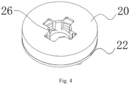
- the first through hole 202 and the second through hole 222 both adopt the central spindle a as a symmetric axis; and moreover, the first through hole 202 and the second through hole 222 are matched with each other to form a through cavity 26 running through the elastic restoring assembly 2, as illustrated by Fig. 4 .
- the fan blades 3 and the elastic restoring assembly 2 are fixed on the turntable 1 by a connecting assembly 4.
- the fan blade 3 includes a base 30 and a blade 32; and the base 30 is connected with the upper cover 20 and includes a third through hole 300 as illustrated by Fig.
- the turntable 1 has a fastener 10 corresponding to the through cavity 26.
- the connecting assembly 4 passes through the third through hole 300 and the through cavity 26 in sequence and is connected with the fastener 10, so that the turntable 1, the elastic restoring assembly 2 and the fan blade 3 are fixed in an extension direction of the central spindle a.
- the connecting assembly 4 may be a bolt assembly, a bolt passes through the through structure, and a nut is arranged in the fastener 10; and the connecting assembly may also be a tenon-and-mortise structure, as long as the turntable 1, the elastic restoring assembly 2 and the fan blade 3 can be fixed in sequence, and the above rotating action is allowed to occur.
- the turntable 1, the elastic restoring assembly 2 and the fan blades 3 are fixed by utilizing the above structure, which may easily cause the problem that the upper cover 20 cannot rotate with the fan blade 3 or the lower cover 2 cannot rotate with the turntable 1.
- the turntable 1 has a lower cover connecting seat 12 corresponding to the lower cover 22; the lower cover connecting seat 12 has an eccentric occlusion member 120 that is arranged eccentrically; the lower cover 22 has a first mating member 224 corresponding to the eccentric occlusion member 120; the eccentric occlusion member 120 may be configured as an eccentric hole on the lower cover connecting seat 12, and the first mating member 224 is arranged as a corresponding convex column, so that, upon the elastic restoring assembly 2 being fixed to the turntable 1 by the connecting assembly 4, the convex column stretches into the hole and prevents the lower cover 22 from rotating circumferentially; and the eccentric occlusion member 120 and the first mating member 224 may also be arranged as a pair of magnets,
- the base 30 includes a connecting tenon 302; in order to realize a similar effect for preventing the upper cover 20 from rotating relative to the base 30, the connecting tenon 302 has circumferentially-protruding tenon teeth 3020 as illustrated by Fig.
- the upper cover 20 has a mortise 204 corresponding to the connecting tenon 302; the mortise 204 has tenon grooves 2040 corresponding to the tenon teeth 3020; upon the connecting tenon 302 being inserted into the mortise 204, the tenon teeth 3020 are inserted into the mortise grooves 2040 and matched with the tenon grooves 2040 to prevent the relative rotation of the upper cover 20 and fan blades 32; and in the present embodiment, a component that prevents the relative rotation and corresponds to upper cover 20 or the lower cover 22 is not limited to the above eccentric occlusion member 120, the connecting tenon 302 or the magnet, etc., and may be any component that can prevent the relative rotation, which is not repeated herein.
- the connecting tenon 302 is arranged at the center of the base 30 and adopts the central spindle a as the symmetric axis; and the third through hole 300 runs through the connecting tenon 302, so that the concentric structure is convenient for the manufacturing, and especially the fan blade 3 that is made of a plastic material is easy to demold.
- a plurality of tenon teeth 3020 are circumferentially protruded out of the connecting tenon 302, and a circumferential size of at least one tenon tooth 3020 is different from the circumferential sizes of other ones of the tenon teeth 3020, so that during the installation, the connecting tenon 302 can only be inserted into the mortise 204 in a unique preset posture.
- the circumferential contour of the turntable 1 is arranged in a circular shape, and a plurality of elastic restoring assemblies 2 and corresponding fan blades 3 are uniformly distributed on the periphery of the turntable 1.
- the fan lamp according to the embodiments of the present invention also has an illuminating module 5, and the fan blades 3 are arranged at an upturned side of the turntable 1; the illuminating module 5 is connected with the turntable 1; and an optical axis b of the illuminating module extends downward, so that, upon the fan lamp being lifted, the fan blades 3 may not block the light emitted from the illuminating module 5.
- the upper cover and the lower cover are used to form the rotatable closed space, the elastic member is received in the closed space, and the fan blades are connected with the turntable through the upper cover and the lower cover, so that the possibility that the lubricating oil is thrown out in the utilization process of the fan can be reduced.
Landscapes
- Engineering & Computer Science (AREA)
- General Engineering & Computer Science (AREA)
- Mechanical Engineering (AREA)
- Structures Of Non-Positive Displacement Pumps (AREA)
Description
- The present invention relates to the field of household appliances, and particularly to a fan lamp.
- Fan lamps may also provide a blowing function on the basis of an illuminating function, and are popular among consumers. Because the blowing function is a seasonal function, fan blades of a fan are often made into a folding type. Upon the fan being switched on, the fan blades are unfolded by a centrifugal force generated by the rotation of a central spindle of the fan, and upon the fan being switched off, the fan blades retract elastically.
- Because a mechanism that controls the elastic retraction of the fan blades may always be lubricated with lubricating oil, the lubricating oil may also be thrown out by the centrifugal force, so as to cause pollution.
-
CN 107 355 395 A describes a ceiling fan, which includes: a hanging member, at least one blade holder, at least one blade, and a rotation limiting mechanism. The hanging member is fixed on a wall. The blade holder is configured in a manner of rotating relative to the hanging member. The blade is pivotly installed on the blade holder through the rotation limiting mechanism, so that the blade can be pivoted between a first position and a second position relative to the blade holder; when the blade holder is static relative to the hanging member, the blade is maintained at a first position; when the blade holder rotates relative to the hanging member, the blade is pivoted to a second position relative to the blade holder. The blade is arranged under the blade holder. -
CN 209 261 912 U describes a telescopic fan blade structure and a ceiling fan lamp. The telescopic fan blade structure comprises a rotating frame, a rotating cover and fan blades, the rotating frame is in a hollow cylinder shape, a torsional spring is arranged in the rotating frame, a rotating shaft of the torsional spring coincides with a center shaft of the rotating frame, a first limiting groove is formed in the inner wall of the rotating frame, and one end of the torsional spring is arranged in the first limiting groove; the rotating cover is pivoted with the rotating frame, the rotating cover is provided with a second limiting groove, and the other end of the torsional spring is arranged in the second limiting groove; the fan blades are fixedly connected with the rotary cover; a connecting rod for connecting a motor is arranged on one side of the rotating frame, is perpendicular to a rotating shaft of the motor when connected with the motor and is positioned on the same plane with the motor. -
CN 207 935 902 U discloses a straight drum type purification fan lamp, which comprises a ceiling fan body, the ceiling fan body comprises a bell for seamlessly docking with the ceiling; a boom for fixing with the lifting ball in the bell; a connecting head for locking a motor, the upper end of the connecting head is fixed with the boom; and a rotating disk, the rotating disk is fixed below the motor, the rotating disc is remote from the outside of the motor for connecting a comma rotating assembly; a blade is fixed to the comma rotating assembly by screws; a pallet is located below the rotating disc, and the pallet is fixed on the motor, the pallet is coupled downwardly to a rotating decorative disc for balancing the rotating decorative disc; a purifying lamp assembly is fixed under the rotating decorative disc, and the purifying lamp assembly is provided with a lamp disc and a net active a carbon filter block, the lamp tray bracket connected to the straight drum light plate is fixed under the rotating decorative disk, the mesh activated carbon filter block is located in the lamp plate, and the side of the lamp plate is provided with a vent hole. The lamp panel is in the shape of a straight drum. The purifying lamp assembly includes an LED color changing light source fixed in the lamp panel, the purifying lamp assembly further includes a lamp cover, the lamp cover is located under the LED color changing light source, and the lamp cover is cylindrically fixed to the lamp panel. The inner bottom of the lampshade is fixed with an air intake panel, and a display is fixed on the air intake panel for displaying various function data, and the air intake panel is further fixed with an inductor for sensing air quality in the environment. When the motor is not activated, the blade is gathered above the rotating decorative disk, and when the motor is started, the comma rotating component is rotated by the centrifugal force, so that the blade is ejected from the inside to the outside. After the motor is turned off, the comma rotating assembly rotates under the tension of a tension spring to retract the blade inwardly. -
CN 208 966 693 U describes an invisible fan and a fan lamp. The invisible fan comprises a rotary disc assembly and a plurality of fan blade assemblies arranged on the rotary disc assembly. The turntable assembly is provided with a turntable and a limiting wheel rotating relative to the turntable; the turntable is provided with a plurality of fan blade fixing parts; the plurality of fan blade fixing parts are annularly arranged around the center of the turntable; each fan blade assembly is provided with a fan blade and a reset elastic piece, the fan blade is provided with a fixing part and a linkage part arranged on one side of the fixing part, the fixing part is arranged on the corresponding fan blade fixing part, the linkage part is connected with the limiting wheel, the reset elastic piece is arranged between the fixing part and the fan blade fixing part, and the two ends of the reset elastic piece are connected with the fixing part and the fan blade fixing part, respectively. - The invention is set out in the claims. Embodiments of the present application provide a fan lamp, to solve the above-mentioned problems.
- Embodiments of the present application adopt the following technical solutions:
- At least one embodiment of the present invention provides a fan lamp, including a turntable, an elastic restoring assembly and fan blades, the fan blades are connected with the turntable through the elastic restoring assembly, the elastic restoring assembly includes an upper cover, a lower cover and an elastic member, two ends of the elastic member are connected with the upper cover and the lower cover respectively, the upper cover can rotate relative to the lower cover and drives the elastic member to be deformed elastically, the fan blades are connected with the upper cover, and the turntable is connected with the lower cover; and the upper cover includes a connecting member, the lower cover includes a connection mating member, the upper cover and the lower cover have the same circumferential contour and are both circular, the upper cover and the lower cover are fastened through a mating action of the connecting member and the connection mating member to form a closed accommodating space, and the elastic member is arranged in the closed accommodating space.
- The upper cover includes a first through hole, the lower cover includes a second through hole, the elastic restoring assembly includes a central spindle, the first through hole and the second through hole are both circular holes with the same circumferential size and both adopt the central spindle as a symmetric axis, and the first through hole and the second through hole can be matched to form a through cavity running through the elastic restoring assembly.
- The fan lamp further includes a connecting assembly, the fan blade includes a blade and a base, the blade is connected with the upper cover through the base, the base includes a third through hole corresponding to the through cavity, the turntable includes a fastener corresponding to the through cavity, the fan blade, the elastic restoring assembly and the turntable are connected sequentially in an extension direction of the central spindle through a mating action of the connecting assembly, the third through hole, the through cavity and the fastener.
- Preferably, the turntable includes a lower cover connecting seat corresponding to the lower cover, the lower cover connecting seat includes an eccentric occlusion member, the eccentric occlusion member is arranged eccentrically at the lower cover connecting seat, the lower cover includes a first mating member corresponding to the eccentric occlusion member, and the lower cover and the lower cover connecting seat can be engaged with each other through a mating action of the eccentric occlusion member and the first mating member.
- The base includes a connecting tenon, the connecting tenon includes tenon teeth protruding in a circumferential direction of the connecting tenon, the upper cover includes a mortise corresponding to the connecting tenon, the mortise includes tenon grooves corresponding to the tenon teeth, upon the connecting tenon being inserted into the tenon grooves, the blade can rotate with the upper cover through a mating action of the tenon teeth and the tenon grooves.
- Preferably, the connecting assembly is a bolt assembly.
- Preferably, the connecting tenon adopts the central spindle as a symmetric axis, and the third through hole runs through the connecting tenon.
- Preferably, a circumferential size of at least one of the tenon teeth is different from circumferential sizes of other ones of the tenon teeth.
- Preferably, the elastic member is a spring, the spring is coaxial with the upper cover and/or the lower cover, one end of the spring is connected with the upper cover, and the other end of the spring is connected with the lower cover.
- Preferably, the circumferential contour of the turntable is circular, and a plurality of elastic restoring assemblies are distributed uniformly on a periphery of the turntable.
- Preferably, the fan lamp further includes an illuminating module, the fan blades are arranged at an upturned side of the turntable, the illuminating module is connected with the turntable, and an optical axis of the illuminating module extends downward.
- According to an embodiment of the present invention, the upper cover and the lower cover are used to form a rotatable closed space, the elastic member is received in the closed space, and the fan blades are connected with the turntable through the upper cover and the lower cover, so that the possibility that the lubricating oil is thrown out in the utilization process of the fan can be reduced.
- The accompanying drawings described here are used for further understanding of the present invention and constitute one part of the present invention. Schematic embodiments of the present invention and the description thereof are used to explain the present invention, and do not constitute an improper limitation to the present invention. In the drawings:
-
Fig. 1 is a schematic diagram of a fan lamp disclosed by an embodiment of the present invention. -
Fig. 2 is a schematic diagram of components of an elastic restoring assembly disclosed by an embodiment of the present invention. -
Fig. 3 is a schematic diagram of a fan blade disclosed by an embodiment of the present invention. -
Fig. 4 is a schematic diagram of the elastic restoring assembly disclosed by an embodiment of the present invention. - 1-Turntable; 2-elastic restoring assembly; 3-fan blade; 4-connecting assembly; 5-illuminating module; 10-fastener; 12-lower cover connecting seat; 20-upper cover; 22-lower cover; 24-elastic member; 26-through cavity; 30-base; 32-blade; 120-eccentric occlusion member; 200-connecting member; 202-first through hole; 204-mortise; 220-connection mating member; 222-second through hole; 224-first mating member; 300-third through hole; 302-connecting tenon; 2040-tenon groove; 3020-tenon tooth; a-central spindle; b-optical axis.
- To make the purpose, technical solutions and advantages of the present invention clearer, the technical solutions of the present invention are described clearly and completely below in combination with specific embodiments of the present invention and corresponding accompanying drawings. Apparently, the described embodiments are only some embodiments of the present invention, but not all embodiments.
- Technical solutions provided by the embodiments of the present invention are described in detail below in conjunction with accompanying drawings.
- An embodiment of the present invention discloses a fan lamp, which includes a turntable 1, an
elastic restoring assembly 2 andfan blades 3, thefan blades 3 are fixed at the turntable 1 through theelastic restoring assembly 2, and the turntable 1 is used to drive theelastic restoring assembly 2 and thefan blades 3 to rotate and provide a centrifugal force for the stretching of thefan blades 3. In the present embodiment, theelastic restoring assembly 2 includes anupper cover 20, alower cover 22 and anelastic member 24, and two ends of theelastic member 24 are connected with theupper cover 20 and thelower cover 22 respectively. In the present embodiment, theelastic member 24 may be a spring, may also be elastic rubber, etc., can be deformed elastically along with the rotation of theupper cover 20 relative to thelower cover 22, and can make the upper cover and lower cover rotate relative to each other in an opposite direction through the elastic recovery. - As illustrated by
Fig. 1 , thefan blades 3 are connected with theupper cover 20, and theturntable 20 is connected with thelower cover 22, so that, upon thefan blades 3 being away from theturntable 20 due to the centrifugal force, thefan blades 3 drive theupper cover 20 to rotate relative to thelower cover 22, and make theelastic member 24 deformed elastically; and upon the centrifugal force disappearing, theelastic member 24 drives thefan blades 3 to rotate back to an original position through the elastic recovery. According to the present invention, theupper cover 20 includes a connectingmember 200, thelower cover 22 has aconnection mating member 220, and theupper cover 20 and thelower cover 22 are both arranged in a circular shape with the same circumferential contour; the connectingmember 200 and themating member 220 may be concentric annular fasteners as illustrated byFig. 1 , and may also be buckles or combinations of plugs and jacks, as long as theupper cover 20 and thelower cover 22 can be fastened with each other and can rotate freely relative to each other. By adopting the structure, the rotation requirement can be met, and a closed accommodating space may be formed between theupper cover 20 and thelower cover 22 at the same time. The closed accommodating space is used to accommodate theelastic member 24. In this way, liquid such as lubricating oil arranged on theelastic member 24 may be possibly limited in the closed accommodating space instead of being thrown out under the centrifugal force. - According to an embodiment of the present invention, the upper cover and the lower cover are used to form a rotatable closed space, the elastic member is received in the closed space, and the fan blades are connected with the turntable through the upper cover and the lower cover, so that the possibility that the lubricating oil is thrown out in the utilization process of the fan can be reduced.
- In order to facilitate the installation of the
fan blades 3 and turntable 1 to theelastic restoring assembly 2, according to the present invention, theupper cover 20 includes a first through hole 202, and thelower cover 22 includes a second throughhole 222. As illustrated byFig. 1 , theelastic restoring assembly 2 has a central spindle a, and theelastic restoring assembly 2 is circumferentially symmetric around the central spindle a. In order to make the first through hole 202 and the second throughhole 222 and internal structures thereof have small internal stress on theelastic restoring assembly 2, according to the present invention, the first through hole 202 and the second throughhole 222 both adopt the central spindle a as a symmetric axis; and moreover, the first through hole 202 and the second throughhole 222 are matched with each other to form a throughcavity 26 running through theelastic restoring assembly 2, as illustrated byFig. 4 . Thefan blades 3 and the elastic restoringassembly 2 are fixed on the turntable 1 by a connecting assembly 4. As illustrated byFig. 1 , thefan blade 3 includes abase 30 and ablade 32; and thebase 30 is connected with theupper cover 20 and includes a third throughhole 300 as illustrated byFig. 1 . The turntable 1 has afastener 10 corresponding to the throughcavity 26. The connecting assembly 4 passes through the third throughhole 300 and the throughcavity 26 in sequence and is connected with thefastener 10, so that the turntable 1, the elastic restoringassembly 2 and thefan blade 3 are fixed in an extension direction of the central spindle a. The connecting assembly 4 may be a bolt assembly, a bolt passes through the through structure, and a nut is arranged in thefastener 10; and the connecting assembly may also be a tenon-and-mortise structure, as long as the turntable 1, the elastic restoringassembly 2 and thefan blade 3 can be fixed in sequence, and the above rotating action is allowed to occur. - However, the turntable 1, the elastic restoring
assembly 2 and thefan blades 3 are fixed by utilizing the above structure, which may easily cause the problem that theupper cover 20 cannot rotate with thefan blade 3 or thelower cover 2 cannot rotate with the turntable 1. In order to avoid the problem, in the present embodiment, the turntable 1 has a lowercover connecting seat 12 corresponding to thelower cover 22; the lowercover connecting seat 12 has aneccentric occlusion member 120 that is arranged eccentrically; thelower cover 22 has afirst mating member 224 corresponding to theeccentric occlusion member 120; theeccentric occlusion member 120 may be configured as an eccentric hole on the lowercover connecting seat 12, and thefirst mating member 224 is arranged as a corresponding convex column, so that, upon the elastic restoringassembly 2 being fixed to the turntable 1 by the connecting assembly 4, the convex column stretches into the hole and prevents thelower cover 22 from rotating circumferentially; and theeccentric occlusion member 120 and thefirst mating member 224 may also be arranged as a pair of magnets, as long as the rotation of thelower cover 22 with respect to the turntable 1 can be prevented. Thebase 30 includes a connectingtenon 302; in order to realize a similar effect for preventing theupper cover 20 from rotating relative to thebase 30, the connectingtenon 302 has circumferentially-protrudingtenon teeth 3020 as illustrated byFig. 1 ; theupper cover 20 has amortise 204 corresponding to the connectingtenon 302; themortise 204 hastenon grooves 2040 corresponding to thetenon teeth 3020; upon the connectingtenon 302 being inserted into themortise 204, thetenon teeth 3020 are inserted into themortise grooves 2040 and matched with thetenon grooves 2040 to prevent the relative rotation of theupper cover 20 andfan blades 32; and in the present embodiment, a component that prevents the relative rotation and corresponds toupper cover 20 or thelower cover 22 is not limited to the aboveeccentric occlusion member 120, the connectingtenon 302 or the magnet, etc., and may be any component that can prevent the relative rotation, which is not repeated herein. - To facilitate the manufacturing, the connecting
tenon 302 is arranged at the center of thebase 30 and adopts the central spindle a as the symmetric axis; and the third throughhole 300 runs through the connectingtenon 302, so that the concentric structure is convenient for the manufacturing, and especially thefan blade 3 that is made of a plastic material is easy to demold. - In order to reduce the internal stress and losses caused by dislocation during the installation, in the present embodiment, as illustrated by
Fig. 1 , a plurality oftenon teeth 3020 are circumferentially protruded out of the connectingtenon 302, and a circumferential size of at least onetenon tooth 3020 is different from the circumferential sizes of other ones of thetenon teeth 3020, so that during the installation, the connectingtenon 302 can only be inserted into themortise 204 in a unique preset posture. - In the present embodiment, in order to facilitate the
fan blades 3 to extend out uniformly when rotating, as illustrated byFig. 1 , the circumferential contour of the turntable 1 is arranged in a circular shape, and a plurality of elastic restoringassemblies 2 andcorresponding fan blades 3 are uniformly distributed on the periphery of the turntable 1. - To realize the illuminating function, the fan lamp according to the embodiments of the present invention also has an illuminating
module 5, and thefan blades 3 are arranged at an upturned side of the turntable 1; the illuminatingmodule 5 is connected with the turntable 1; and an optical axis b of the illuminating module extends downward, so that, upon the fan lamp being lifted, thefan blades 3 may not block the light emitted from the illuminatingmodule 5. - In conclusion, according to the embodiments of the present invention, the upper cover and the lower cover are used to form the rotatable closed space, the elastic member is received in the closed space, and the fan blades are connected with the turntable through the upper cover and the lower cover, so that the possibility that the lubricating oil is thrown out in the utilization process of the fan can be reduced.
- The above embodiments of the present invention focus on differences among the various embodiments. As long as different optimization features among the various embodiments are not contradictory, the embodiments can be combined to form a better embodiment, which is not repeated here for brevity.
- The above description is only embodiments of the present invention and is not used to limit the present invention. For those skilled in the art, various changes and variations of the present invention can be made, as long as they are contained within the scope of the claims.
Claims (8)
- A fan lamp, comprising a turntable (1), an elastic restoring assembly (2) and fan blades (3), whereinthe fan blades (3) are connected with the turntable (1) through the elastic restoring assembly (2), the elastic restoring assembly (2) comprises an upper cover (20), a lower cover (22) and an elastic member (24), two ends of the elastic member (24) are connected with the upper cover (20) and the lower cover (22) respectively, the upper cover (20) can rotate relative to the lower cover (22) and drives the elastic member (24) to be deformed elastically, the fan blades (3) are connected with the upper cover (20), and the turntable (1) is connected with the lower cover (22); andthe upper cover (20) comprises a connecting member (200), the lower cover (22) comprises a connection mating member (220), the upper cover (20) and the lower cover (22) have the same circumferential contour and are both circular, the upper cover (20) and the lower cover (22) are fastened through a mating action of the connecting member (200) and the connection mating member (220) to form a closed accommodating space, and the elastic member (24) is arranged in the closed accommodating space;wherein the upper cover (20) comprises a first through hole (202), the lower cover (22) comprises a second through hole (222), the elastic restoring assembly (2) comprises a central spindle (a), the first through hole (202) and the second through hole (222) are both circular holes with the same circumferential size and both adopt the central spindle (a) as a symmetric axis, and the first through hole (202) and the second through hole (222) can be matched to form a through cavity (26) running through the elastic restoring assembly (2);wherein the fan lamp further comprises a connecting assembly (4), wherein the fan blade (3) comprises a blade (32) and a base (30), the blade (32) is connected with the upper cover (20) through the base (30), characterized in thatthe base (30) comprises a third through hole (300) corresponding to the through cavity (26), the turntable (1) comprises a fastener (10) corresponding to the through cavity (26), the fan blade (3), the elastic restoring assembly (2) and the turntable (1) are connected sequentially in an extension direction of the central spindle (a) through a mating action of the connecting assembly (4), the third through hole (300), the through cavity (26) and the fastener (10);and in that the base (30) comprises a connecting tenon (302), the connecting tenon (302) comprises tenon teeth (3020) protruding in a circumferential direction of the connecting tenon (302), the upper cover (20) comprises a mortise (204) corresponding to the connecting tenon (302), the mortise (204) comprises tenon grooves (2040) corresponding to the tenon teeth (3020), upon the connecting tenon (302) being inserted into the tenon grooves (2040), the blade (32) can rotate with the upper cover (20) through a mating action of the tenon teeth (3020) and the tenon grooves (2040).
- The fan lamp according to claim 1, wherein the turntable (1) comprises a lower cover connecting seat (12) corresponding to the lower cover (22), the lower cover connecting seat (12) comprises an eccentric occlusion member (120), the eccentric occlusion member (120) is arranged eccentrically at the lower cover connecting seat (12), the lower cover (22) comprises a first mating member (224) corresponding to the eccentric occlusion member (120), and the lower cover (22) and the lower cover connecting seat (12) can be engaged with each other through a mating action of the eccentric occlusion member (120) and the first mating member (224).
- The fan lamp according to claim 1, wherein the connecting assembly (4) is a bolt assembly.
- The fan lamp according to claim 1, wherein the connecting tenon (302) adopts the central spindle (a) as a symmetric axis, and the third through hole (300) runs through the connecting tenon (302).
- The fan lamp according to claim 1, wherein a circumferential size of at least one of the tenon teeth (3020) is different from circumferential sizes of other ones of the tenon teeth (3020).
- The fan lamp according to claim 1, wherein the elastic member (24) is a spring, the spring is coaxial with the upper cover (20) and/or the lower cover (22), one end of the spring is connected with the upper cover (20), and the other end of the spring is connected with the lower cover (22).
- The fan lamp according to any one of claims 1-5, wherein the circumferential contour of the turntable (1) is circular, and a plurality of elastic restoring assemblies (2) are distributed uniformly on a periphery of the turntable (1).
- The fan lamp according to any one of claims 1-6, further comprising an illuminating module (5), wherein the fan blades (3) are arranged at an upturned side of the turntable (1), the illuminating module (5) is connected with the turntable (1), and an optical axis (b) of the illuminating module (5) extends downward.
Applications Claiming Priority (2)
| Application Number | Priority Date | Filing Date | Title |
|---|---|---|---|
| CN201921677855.2U CN210769517U (en) | 2019-10-09 | 2019-10-09 | a fan light |
| PCT/CN2020/119240 WO2021068827A1 (en) | 2019-10-09 | 2020-09-30 | Fan lamp |
Publications (3)
| Publication Number | Publication Date |
|---|---|
| EP3974658A1 EP3974658A1 (en) | 2022-03-30 |
| EP3974658A4 EP3974658A4 (en) | 2022-11-02 |
| EP3974658B1 true EP3974658B1 (en) | 2024-11-20 |
Family
ID=71066135
Family Applications (1)
| Application Number | Title | Priority Date | Filing Date |
|---|---|---|---|
| EP20874884.8A Active EP3974658B1 (en) | 2019-10-09 | 2020-09-30 | Fan lamp |
Country Status (4)
| Country | Link |
|---|---|
| US (1) | US11879477B2 (en) |
| EP (1) | EP3974658B1 (en) |
| CN (1) | CN210769517U (en) |
| WO (1) | WO2021068827A1 (en) |
Families Citing this family (3)
| Publication number | Priority date | Publication date | Assignee | Title |
|---|---|---|---|---|
| CN210769517U (en) | 2019-10-09 | 2020-06-16 | 欧普照明股份有限公司 | a fan light |
| WO2024078459A1 (en) * | 2022-10-09 | 2024-04-18 | 苏州欧普照明有限公司 | Fan lamp |
| CN115654449A (en) * | 2022-10-09 | 2023-01-31 | 欧普照明股份有限公司 | fan light |
Family Cites Families (20)
| Publication number | Priority date | Publication date | Assignee | Title |
|---|---|---|---|---|
| US6158964A (en) * | 1997-03-24 | 2000-12-12 | Minka Lighting, Inc. | Downrod assembly for a ceiling fan and mounting system for same |
| US8790085B2 (en) * | 2005-07-13 | 2014-07-29 | Beacon Lighting International Limited | Combined ceiling fan and light fitting |
| WO2008144596A1 (en) * | 2007-05-18 | 2008-11-27 | Swiss Module Group, Llc | Fan with power adjustable housing |
| US8092180B2 (en) * | 2009-02-10 | 2012-01-10 | Pan Air Electric Co., Ltd | Blade assembly for a ceiling fan |
| CN202772705U (en) * | 2012-08-21 | 2013-03-06 | 简伟松 | Sealed oil storage structure motor and fan using same |
| TWI577931B (en) * | 2015-05-28 | 2017-04-11 | 建準電機工業股份有限公司 | Motor of ceiling fan with illuminating module |
| CN205173002U (en) * | 2015-11-20 | 2016-04-20 | 刘东北 | Stealthy ceiling fan lamp of decorating of enhancement mode fan leaf |
| TW201740024A (en) * | 2016-05-10 | 2017-11-16 | 巨鎧實業股份有限公司 | Ceiling fan structure having at least one blade which is expanded when being in rotation and collapsed when being not in rotation |
| CN106870415A (en) * | 2017-03-11 | 2017-06-20 | 周祖宏 | A kind of stealthy fan blade Lamp with ceiling fan |
| CN207935110U (en) * | 2017-10-18 | 2018-10-02 | 刘东北 | A kind of round drum type stealth fan Lamp with ceiling fan |
| US10851798B2 (en) * | 2017-10-23 | 2020-12-01 | Swiss Module Group Llc | Deployable fan with linear actuator |
| WO2019095470A1 (en) * | 2017-11-20 | 2019-05-23 | 中山市风美照明科技有限公司 | Light-emitting ceiling fan having hidden blades |
| CN207935902U (en) * | 2018-03-30 | 2018-10-02 | 刘东北 | A kind of straight drum type purification fan lamp |
| CN208950910U (en) * | 2018-08-06 | 2019-06-07 | 付小平 | A kind of fan lamp fan blade linkage structure |
| CN209261912U (en) * | 2018-09-03 | 2019-08-16 | 唐宁 | Retractable fan blade structure and ceiling fan light |
| CN208966693U (en) * | 2018-09-27 | 2019-06-11 | 欧普照明股份有限公司 | A kind of stealthy fan and fan lamp |
| WO2020063551A1 (en) * | 2018-09-27 | 2020-04-02 | 欧普照明股份有限公司 | Invisible fan and fan lamp |
| CN109114038A (en) * | 2018-09-27 | 2019-01-01 | 欧普照明股份有限公司 | A kind of stealthy fan and fan lamp |
| CN210769517U (en) * | 2019-10-09 | 2020-06-16 | 欧普照明股份有限公司 | a fan light |
| US10935043B1 (en) * | 2020-02-24 | 2021-03-02 | Pan Air Electric Co., Ltd. | Assembly of blade assembly bracket and blade of ceiling fan |
-
2019
- 2019-10-09 CN CN201921677855.2U patent/CN210769517U/en active Active
-
2020
- 2020-09-30 EP EP20874884.8A patent/EP3974658B1/en active Active
- 2020-09-30 WO PCT/CN2020/119240 patent/WO2021068827A1/en not_active Ceased
-
2021
- 2021-12-27 US US17/563,032 patent/US11879477B2/en active Active
Also Published As
| Publication number | Publication date |
|---|---|
| US20220120286A1 (en) | 2022-04-21 |
| EP3974658A4 (en) | 2022-11-02 |
| CN210769517U (en) | 2020-06-16 |
| WO2021068827A1 (en) | 2021-04-15 |
| EP3974658A1 (en) | 2022-03-30 |
| US11879477B2 (en) | 2024-01-23 |
Similar Documents
| Publication | Publication Date | Title |
|---|---|---|
| US11873823B1 (en) | Fan component of fan lamp and fan lamp assembly | |
| US8292585B2 (en) | Fan device having simultaneously foldable blades | |
| US12181143B2 (en) | Fan lamp | |
| US11879477B2 (en) | Fan lamp | |
| CN118934675A (en) | Fan Light | |
| CN105274783B (en) | A deceleration clutch clutch device and deceleration clutch | |
| EP4105494B1 (en) | Invisible fan and fan lamp | |
| WO2022184078A1 (en) | Fan assembly and fan lamp | |
| CN214247743U (en) | Fan lamp | |
| CN212296975U (en) | Fan lamp | |
| CN220268004U (en) | Fan blade opening and closing mechanism and fan lamp | |
| CA2704302C (en) | Fan device having simultaneously foldable blades | |
| CN219299582U (en) | Electric fan | |
| AU2010100481A4 (en) | Fan device having simultaneously foldable blades | |
| CN212407105U (en) | Fan lamp | |
| EP2388483A1 (en) | Fan device having simultaneously foldable blades | |
| CN208950910U (en) | A kind of fan lamp fan blade linkage structure | |
| CN216715983U (en) | Telescopic universal focusing lamp | |
| CN220337400U (en) | A synchronous pulley device and lamp | |
| CN217209232U (en) | Lampshade mounting structure and lamp | |
| CN115405900B (en) | An intelligent lighting control system | |
| CN205447646U (en) | Rotatory pattern dish of stage lighting | |
| CN219242252U (en) | Fan lamp with novel structure | |
| CN221279339U (en) | Lamp bracket and lighting device | |
| CN222142770U (en) | A multifunctional ceiling lamp |
Legal Events
| Date | Code | Title | Description |
|---|---|---|---|
| STAA | Information on the status of an ep patent application or granted ep patent |
Free format text: STATUS: THE INTERNATIONAL PUBLICATION HAS BEEN MADE |
|
| PUAI | Public reference made under article 153(3) epc to a published international application that has entered the european phase |
Free format text: ORIGINAL CODE: 0009012 |
|
| STAA | Information on the status of an ep patent application or granted ep patent |
Free format text: STATUS: REQUEST FOR EXAMINATION WAS MADE |
|
| 17P | Request for examination filed |
Effective date: 20211221 |
|
| AK | Designated contracting states |
Kind code of ref document: A1 Designated state(s): AL AT BE BG CH CY CZ DE DK EE ES FI FR GB GR HR HU IE IS IT LI LT LU LV MC MK MT NL NO PL PT RO RS SE SI SK SM TR |
|
| A4 | Supplementary search report drawn up and despatched |
Effective date: 20220929 |
|
| RIC1 | Information provided on ipc code assigned before grant |
Ipc: F04D 25/08 20060101ALI20220923BHEP Ipc: F21V 33/00 20060101ALI20220923BHEP Ipc: F04D 29/32 20060101ALI20220923BHEP Ipc: F04D 29/36 20060101ALI20220923BHEP Ipc: F04D 29/34 20060101AFI20220923BHEP |
|
| DAV | Request for validation of the european patent (deleted) | ||
| DAX | Request for extension of the european patent (deleted) | ||
| GRAP | Despatch of communication of intention to grant a patent |
Free format text: ORIGINAL CODE: EPIDOSNIGR1 |
|
| STAA | Information on the status of an ep patent application or granted ep patent |
Free format text: STATUS: GRANT OF PATENT IS INTENDED |
|
| INTG | Intention to grant announced |
Effective date: 20240612 |
|
| GRAS | Grant fee paid |
Free format text: ORIGINAL CODE: EPIDOSNIGR3 |
|
| GRAA | (expected) grant |
Free format text: ORIGINAL CODE: 0009210 |
|
| STAA | Information on the status of an ep patent application or granted ep patent |
Free format text: STATUS: THE PATENT HAS BEEN GRANTED |
|
| AK | Designated contracting states |
Kind code of ref document: B1 Designated state(s): AL AT BE BG CH CY CZ DE DK EE ES FI FR GB GR HR HU IE IS IT LI LT LU LV MC MK MT NL NO PL PT RO RS SE SI SK SM TR |
|
| REG | Reference to a national code |
Ref country code: GB Ref legal event code: FG4D |
|
| REG | Reference to a national code |
Ref country code: CH Ref legal event code: EP |
|
| REG | Reference to a national code |
Ref country code: DE Ref legal event code: R096 Ref document number: 602020041843 Country of ref document: DE |
|
| REG | Reference to a national code |
Ref country code: IE Ref legal event code: FG4D |
|
| REG | Reference to a national code |
Ref country code: NL Ref legal event code: FP |
|
| REG | Reference to a national code |
Ref country code: LT Ref legal event code: MG9D |
|
| PG25 | Lapsed in a contracting state [announced via postgrant information from national office to epo] |
Ref country code: IS Free format text: LAPSE BECAUSE OF FAILURE TO SUBMIT A TRANSLATION OF THE DESCRIPTION OR TO PAY THE FEE WITHIN THE PRESCRIBED TIME-LIMIT Effective date: 20250320 Ref country code: PT Free format text: LAPSE BECAUSE OF FAILURE TO SUBMIT A TRANSLATION OF THE DESCRIPTION OR TO PAY THE FEE WITHIN THE PRESCRIBED TIME-LIMIT Effective date: 20250320 Ref country code: HR Free format text: LAPSE BECAUSE OF FAILURE TO SUBMIT A TRANSLATION OF THE DESCRIPTION OR TO PAY THE FEE WITHIN THE PRESCRIBED TIME-LIMIT Effective date: 20241120 |
|
| PG25 | Lapsed in a contracting state [announced via postgrant information from national office to epo] |
Ref country code: FI Free format text: LAPSE BECAUSE OF FAILURE TO SUBMIT A TRANSLATION OF THE DESCRIPTION OR TO PAY THE FEE WITHIN THE PRESCRIBED TIME-LIMIT Effective date: 20241120 |
|
| REG | Reference to a national code |
Ref country code: AT Ref legal event code: MK05 Ref document number: 1743815 Country of ref document: AT Kind code of ref document: T Effective date: 20241120 |
|
| PG25 | Lapsed in a contracting state [announced via postgrant information from national office to epo] |
Ref country code: BG Free format text: LAPSE BECAUSE OF FAILURE TO SUBMIT A TRANSLATION OF THE DESCRIPTION OR TO PAY THE FEE WITHIN THE PRESCRIBED TIME-LIMIT Effective date: 20241120 |
|
| PG25 | Lapsed in a contracting state [announced via postgrant information from national office to epo] |
Ref country code: ES Free format text: LAPSE BECAUSE OF FAILURE TO SUBMIT A TRANSLATION OF THE DESCRIPTION OR TO PAY THE FEE WITHIN THE PRESCRIBED TIME-LIMIT Effective date: 20241120 |
|
| PG25 | Lapsed in a contracting state [announced via postgrant information from national office to epo] |
Ref country code: NO Free format text: LAPSE BECAUSE OF FAILURE TO SUBMIT A TRANSLATION OF THE DESCRIPTION OR TO PAY THE FEE WITHIN THE PRESCRIBED TIME-LIMIT Effective date: 20250220 |
|
| PG25 | Lapsed in a contracting state [announced via postgrant information from national office to epo] |
Ref country code: LV Free format text: LAPSE BECAUSE OF FAILURE TO SUBMIT A TRANSLATION OF THE DESCRIPTION OR TO PAY THE FEE WITHIN THE PRESCRIBED TIME-LIMIT Effective date: 20241120 Ref country code: GR Free format text: LAPSE BECAUSE OF FAILURE TO SUBMIT A TRANSLATION OF THE DESCRIPTION OR TO PAY THE FEE WITHIN THE PRESCRIBED TIME-LIMIT Effective date: 20250221 Ref country code: AT Free format text: LAPSE BECAUSE OF FAILURE TO SUBMIT A TRANSLATION OF THE DESCRIPTION OR TO PAY THE FEE WITHIN THE PRESCRIBED TIME-LIMIT Effective date: 20241120 |
|
| PG25 | Lapsed in a contracting state [announced via postgrant information from national office to epo] |
Ref country code: PL Free format text: LAPSE BECAUSE OF FAILURE TO SUBMIT A TRANSLATION OF THE DESCRIPTION OR TO PAY THE FEE WITHIN THE PRESCRIBED TIME-LIMIT Effective date: 20241120 |
|
| PG25 | Lapsed in a contracting state [announced via postgrant information from national office to epo] |
Ref country code: RS Free format text: LAPSE BECAUSE OF FAILURE TO SUBMIT A TRANSLATION OF THE DESCRIPTION OR TO PAY THE FEE WITHIN THE PRESCRIBED TIME-LIMIT Effective date: 20250220 |
|
| PG25 | Lapsed in a contracting state [announced via postgrant information from national office to epo] |
Ref country code: SM Free format text: LAPSE BECAUSE OF FAILURE TO SUBMIT A TRANSLATION OF THE DESCRIPTION OR TO PAY THE FEE WITHIN THE PRESCRIBED TIME-LIMIT Effective date: 20241120 |
|
| PG25 | Lapsed in a contracting state [announced via postgrant information from national office to epo] |
Ref country code: DK Free format text: LAPSE BECAUSE OF FAILURE TO SUBMIT A TRANSLATION OF THE DESCRIPTION OR TO PAY THE FEE WITHIN THE PRESCRIBED TIME-LIMIT Effective date: 20241120 |
|
| PG25 | Lapsed in a contracting state [announced via postgrant information from national office to epo] |
Ref country code: EE Free format text: LAPSE BECAUSE OF FAILURE TO SUBMIT A TRANSLATION OF THE DESCRIPTION OR TO PAY THE FEE WITHIN THE PRESCRIBED TIME-LIMIT Effective date: 20241120 |
|
| PG25 | Lapsed in a contracting state [announced via postgrant information from national office to epo] |
Ref country code: RO Free format text: LAPSE BECAUSE OF FAILURE TO SUBMIT A TRANSLATION OF THE DESCRIPTION OR TO PAY THE FEE WITHIN THE PRESCRIBED TIME-LIMIT Effective date: 20241120 |
|
| PG25 | Lapsed in a contracting state [announced via postgrant information from national office to epo] |
Ref country code: SK Free format text: LAPSE BECAUSE OF FAILURE TO SUBMIT A TRANSLATION OF THE DESCRIPTION OR TO PAY THE FEE WITHIN THE PRESCRIBED TIME-LIMIT Effective date: 20241120 |
|
| PG25 | Lapsed in a contracting state [announced via postgrant information from national office to epo] |
Ref country code: CZ Free format text: LAPSE BECAUSE OF FAILURE TO SUBMIT A TRANSLATION OF THE DESCRIPTION OR TO PAY THE FEE WITHIN THE PRESCRIBED TIME-LIMIT Effective date: 20241120 |
|
| PG25 | Lapsed in a contracting state [announced via postgrant information from national office to epo] |
Ref country code: IT Free format text: LAPSE BECAUSE OF FAILURE TO SUBMIT A TRANSLATION OF THE DESCRIPTION OR TO PAY THE FEE WITHIN THE PRESCRIBED TIME-LIMIT Effective date: 20241120 |
|
| REG | Reference to a national code |
Ref country code: DE Ref legal event code: R097 Ref document number: 602020041843 Country of ref document: DE |
|
| PG25 | Lapsed in a contracting state [announced via postgrant information from national office to epo] |
Ref country code: SE Free format text: LAPSE BECAUSE OF FAILURE TO SUBMIT A TRANSLATION OF THE DESCRIPTION OR TO PAY THE FEE WITHIN THE PRESCRIBED TIME-LIMIT Effective date: 20241120 |
|
| PLBE | No opposition filed within time limit |
Free format text: ORIGINAL CODE: 0009261 |
|
| STAA | Information on the status of an ep patent application or granted ep patent |
Free format text: STATUS: NO OPPOSITION FILED WITHIN TIME LIMIT |
|
| PGFP | Annual fee paid to national office [announced via postgrant information from national office to epo] |
Ref country code: DE Payment date: 20250916 Year of fee payment: 6 |
|
| PGFP | Annual fee paid to national office [announced via postgrant information from national office to epo] |
Ref country code: NL Payment date: 20250909 Year of fee payment: 6 |
|
| PGFP | Annual fee paid to national office [announced via postgrant information from national office to epo] |
Ref country code: BE Payment date: 20250919 Year of fee payment: 6 Ref country code: GB Payment date: 20250919 Year of fee payment: 6 |
|
| PGFP | Annual fee paid to national office [announced via postgrant information from national office to epo] |
Ref country code: FR Payment date: 20250929 Year of fee payment: 6 |
|
| 26N | No opposition filed |
Effective date: 20250821 |
|
| REG | Reference to a national code |
Ref country code: CH Ref legal event code: H13 Free format text: ST27 STATUS EVENT CODE: U-0-0-H10-H13 (AS PROVIDED BY THE NATIONAL OFFICE) Effective date: 20260504 |
|
| PG25 | Lapsed in a contracting state [announced via postgrant information from national office to epo] |
Ref country code: LU Free format text: LAPSE BECAUSE OF NON-PAYMENT OF DUE FEES Effective date: 20250930 |
|
| PG25 | Lapsed in a contracting state [announced via postgrant information from national office to epo] |
Ref country code: LT Free format text: LAPSE BECAUSE OF FAILURE TO SUBMIT A TRANSLATION OF THE DESCRIPTION OR TO PAY THE FEE WITHIN THE PRESCRIBED TIME-LIMIT Effective date: 20241120 |
|
| PG25 | Lapsed in a contracting state [announced via postgrant information from national office to epo] |
Ref country code: MC Free format text: LAPSE BECAUSE OF FAILURE TO SUBMIT A TRANSLATION OF THE DESCRIPTION OR TO PAY THE FEE WITHIN THE PRESCRIBED TIME-LIMIT Effective date: 20241120 |
|
| PG25 | Lapsed in a contracting state [announced via postgrant information from national office to epo] |
Ref country code: CH Free format text: LAPSE BECAUSE OF NON-PAYMENT OF DUE FEES Effective date: 20250930 Ref country code: IE Free format text: LAPSE BECAUSE OF NON-PAYMENT OF DUE FEES Effective date: 20250930 |