EP3974404A1 - Method for repairing composite components and associated infiltration systems and methods - Google Patents
Method for repairing composite components and associated infiltration systems and methods Download PDFInfo
- Publication number
- EP3974404A1 EP3974404A1 EP21193237.1A EP21193237A EP3974404A1 EP 3974404 A1 EP3974404 A1 EP 3974404A1 EP 21193237 A EP21193237 A EP 21193237A EP 3974404 A1 EP3974404 A1 EP 3974404A1
- Authority
- EP
- European Patent Office
- Prior art keywords
- heating
- temperature
- heating element
- composite component
- repair
- Prior art date
- Legal status (The legal status is an assumption and is not a legal conclusion. Google has not performed a legal analysis and makes no representation as to the accuracy of the status listed.)
- Pending
Links
Images



Classifications
-
- C—CHEMISTRY; METALLURGY
- C04—CEMENTS; CONCRETE; ARTIFICIAL STONE; CERAMICS; REFRACTORIES
- C04B—LIME, MAGNESIA; SLAG; CEMENTS; COMPOSITIONS THEREOF, e.g. MORTARS, CONCRETE OR LIKE BUILDING MATERIALS; ARTIFICIAL STONE; CERAMICS; REFRACTORIES; TREATMENT OF NATURAL STONE
- C04B35/00—Shaped ceramic products characterised by their composition; Ceramics compositions; Processing powders of inorganic compounds preparatory to the manufacturing of ceramic products
- C04B35/71—Ceramic products containing macroscopic reinforcing agents
- C04B35/78—Ceramic products containing macroscopic reinforcing agents containing non-metallic materials
- C04B35/80—Fibres, filaments, whiskers, platelets, or the like
-
- B—PERFORMING OPERATIONS; TRANSPORTING
- B29—WORKING OF PLASTICS; WORKING OF SUBSTANCES IN A PLASTIC STATE IN GENERAL
- B29C—SHAPING OR JOINING OF PLASTICS; SHAPING OF MATERIAL IN A PLASTIC STATE, NOT OTHERWISE PROVIDED FOR; AFTER-TREATMENT OF THE SHAPED PRODUCTS, e.g. REPAIRING
- B29C73/00—Repairing of articles made from plastics or substances in a plastic state, e.g. of articles shaped or produced by using techniques covered by this subclass or subclass B29D
- B29C73/02—Repairing of articles made from plastics or substances in a plastic state, e.g. of articles shaped or produced by using techniques covered by this subclass or subclass B29D using liquid or paste-like material
- B29C73/025—Repairing of articles made from plastics or substances in a plastic state, e.g. of articles shaped or produced by using techniques covered by this subclass or subclass B29D using liquid or paste-like material fed under pressure
-
- F—MECHANICAL ENGINEERING; LIGHTING; HEATING; WEAPONS; BLASTING
- F01—MACHINES OR ENGINES IN GENERAL; ENGINE PLANTS IN GENERAL; STEAM ENGINES
- F01D—NON-POSITIVE DISPLACEMENT MACHINES OR ENGINES, e.g. STEAM TURBINES
- F01D5/00—Blades; Blade-carrying members; Heating, heat-insulating, cooling or antivibration means on the blades or the members
- F01D5/005—Repairing methods or devices
-
- B—PERFORMING OPERATIONS; TRANSPORTING
- B29—WORKING OF PLASTICS; WORKING OF SUBSTANCES IN A PLASTIC STATE IN GENERAL
- B29C—SHAPING OR JOINING OF PLASTICS; SHAPING OF MATERIAL IN A PLASTIC STATE, NOT OTHERWISE PROVIDED FOR; AFTER-TREATMENT OF THE SHAPED PRODUCTS, e.g. REPAIRING
- B29C73/00—Repairing of articles made from plastics or substances in a plastic state, e.g. of articles shaped or produced by using techniques covered by this subclass or subclass B29D
- B29C73/04—Repairing of articles made from plastics or substances in a plastic state, e.g. of articles shaped or produced by using techniques covered by this subclass or subclass B29D using preformed elements
- B29C73/10—Repairing of articles made from plastics or substances in a plastic state, e.g. of articles shaped or produced by using techniques covered by this subclass or subclass B29D using preformed elements using patches sealing on the surface of the article
- B29C73/12—Apparatus therefor, e.g. for applying
-
- C—CHEMISTRY; METALLURGY
- C04—CEMENTS; CONCRETE; ARTIFICIAL STONE; CERAMICS; REFRACTORIES
- C04B—LIME, MAGNESIA; SLAG; CEMENTS; COMPOSITIONS THEREOF, e.g. MORTARS, CONCRETE OR LIKE BUILDING MATERIALS; ARTIFICIAL STONE; CERAMICS; REFRACTORIES; TREATMENT OF NATURAL STONE
- C04B35/00—Shaped ceramic products characterised by their composition; Ceramics compositions; Processing powders of inorganic compounds preparatory to the manufacturing of ceramic products
- C04B35/515—Shaped ceramic products characterised by their composition; Ceramics compositions; Processing powders of inorganic compounds preparatory to the manufacturing of ceramic products based on non-oxide ceramics
- C04B35/56—Shaped ceramic products characterised by their composition; Ceramics compositions; Processing powders of inorganic compounds preparatory to the manufacturing of ceramic products based on non-oxide ceramics based on carbides or oxycarbides
- C04B35/565—Shaped ceramic products characterised by their composition; Ceramics compositions; Processing powders of inorganic compounds preparatory to the manufacturing of ceramic products based on non-oxide ceramics based on carbides or oxycarbides based on silicon carbide
- C04B35/573—Shaped ceramic products characterised by their composition; Ceramics compositions; Processing powders of inorganic compounds preparatory to the manufacturing of ceramic products based on non-oxide ceramics based on carbides or oxycarbides based on silicon carbide obtained by reaction sintering or recrystallisation
-
- C—CHEMISTRY; METALLURGY
- C04—CEMENTS; CONCRETE; ARTIFICIAL STONE; CERAMICS; REFRACTORIES
- C04B—LIME, MAGNESIA; SLAG; CEMENTS; COMPOSITIONS THEREOF, e.g. MORTARS, CONCRETE OR LIKE BUILDING MATERIALS; ARTIFICIAL STONE; CERAMICS; REFRACTORIES; TREATMENT OF NATURAL STONE
- C04B37/00—Joining burned ceramic articles with other burned ceramic articles or other articles by heating
- C04B37/001—Joining burned ceramic articles with other burned ceramic articles or other articles by heating directly with other burned ceramic articles
-
- F—MECHANICAL ENGINEERING; LIGHTING; HEATING; WEAPONS; BLASTING
- F01—MACHINES OR ENGINES IN GENERAL; ENGINE PLANTS IN GENERAL; STEAM ENGINES
- F01D—NON-POSITIVE DISPLACEMENT MACHINES OR ENGINES, e.g. STEAM TURBINES
- F01D25/00—Component parts, details, or accessories, not provided for in, or of interest apart from, other groups
-
- F—MECHANICAL ENGINEERING; LIGHTING; HEATING; WEAPONS; BLASTING
- F01—MACHINES OR ENGINES IN GENERAL; ENGINE PLANTS IN GENERAL; STEAM ENGINES
- F01D—NON-POSITIVE DISPLACEMENT MACHINES OR ENGINES, e.g. STEAM TURBINES
- F01D25/00—Component parts, details, or accessories, not provided for in, or of interest apart from, other groups
- F01D25/005—Selecting particular materials
-
- F—MECHANICAL ENGINEERING; LIGHTING; HEATING; WEAPONS; BLASTING
- F01—MACHINES OR ENGINES IN GENERAL; ENGINE PLANTS IN GENERAL; STEAM ENGINES
- F01D—NON-POSITIVE DISPLACEMENT MACHINES OR ENGINES, e.g. STEAM TURBINES
- F01D5/00—Blades; Blade-carrying members; Heating, heat-insulating, cooling or antivibration means on the blades or the members
- F01D5/12—Blades
- F01D5/28—Selecting particular materials; Particular measures relating thereto; Measures against erosion or corrosion
-
- B—PERFORMING OPERATIONS; TRANSPORTING
- B29—WORKING OF PLASTICS; WORKING OF SUBSTANCES IN A PLASTIC STATE IN GENERAL
- B29L—INDEXING SCHEME ASSOCIATED WITH SUBCLASS B29C, RELATING TO PARTICULAR ARTICLES
- B29L2031/00—Other particular articles
- B29L2031/748—Machines or parts thereof not otherwise provided for
- B29L2031/7504—Turbines
-
- C—CHEMISTRY; METALLURGY
- C04—CEMENTS; CONCRETE; ARTIFICIAL STONE; CERAMICS; REFRACTORIES
- C04B—LIME, MAGNESIA; SLAG; CEMENTS; COMPOSITIONS THEREOF, e.g. MORTARS, CONCRETE OR LIKE BUILDING MATERIALS; ARTIFICIAL STONE; CERAMICS; REFRACTORIES; TREATMENT OF NATURAL STONE
- C04B2235/00—Aspects relating to ceramic starting mixtures or sintered ceramic products
- C04B2235/60—Aspects relating to the preparation, properties or mechanical treatment of green bodies or pre-forms
- C04B2235/616—Liquid infiltration of green bodies or pre-forms
-
- F—MECHANICAL ENGINEERING; LIGHTING; HEATING; WEAPONS; BLASTING
- F01—MACHINES OR ENGINES IN GENERAL; ENGINE PLANTS IN GENERAL; STEAM ENGINES
- F01D—NON-POSITIVE DISPLACEMENT MACHINES OR ENGINES, e.g. STEAM TURBINES
- F01D5/00—Blades; Blade-carrying members; Heating, heat-insulating, cooling or antivibration means on the blades or the members
- F01D5/12—Blades
- F01D5/28—Selecting particular materials; Particular measures relating thereto; Measures against erosion or corrosion
- F01D5/282—Selecting composite materials, e.g. blades with reinforcing filaments
Definitions
- the present disclosure generally pertains to methods for repairing composite components, such as turbomachine components, and, more specifically, to methods for repairing composite components and associated infiltration systems and methods.
- CMC ceramic matrix composite
- gas turbine components formed from CMC materials can be quite expensive.
- a CMC gas turbine component becomes worn or damaged, it is desirable to repair, rather than replace, the component.
- methods of repairing CMC components have been developed. Specifically, the worn or damaged portion(s) of a CMC component may be removed and replaced with new CMC material. In such methods, the entire CMC component is heated to the melting temperature of its matrix material, thereby allowing the new CMC material to fuse with the existing CMC material. Such heating may, however, cause the matrix material of portions of the CMC component not being repaired to liquify and flow out of the component. Conversely, heating only the portion of the CMC component adjacent to the new CMC material to the melting point of the matrix material may result the formation of stress cracks within the component.
- the present subject matter is directed to a method for repairing composite components.
- the method includes positioning repair material within a repair region of a composite component formed of a composite material. Furthermore, the method includes heating the repair region to a first temperature. Additionally, the method includes heating a remaining portion of the composite component to a second temperature. Moreover, the method includes melt infiltrating the repair region with an infiltrant to densify the repair material.
- the first temperature is at or above a melting point of the infiltrant and the second temperature is less than the melting point.
- the present subject matter is directed to a method of infiltrating composite components.
- the method includes heating a first portion of a composite component to a first temperature. Furthermore, the method includes heating a second portion of the composite component to a second temperature, with the second portion being adjacent to the first portion. Moreover, the method includes heating a third portion of the composite component to a third temperature. Additionally, the method includes melt infiltrating the composite component with an infiltrant to densify the first portion of the composite component.
- the first temperature is at or above a melting point of the infiltrant and the second and third temperatures are less than the melting point.
- the present subject matter is directed to a system for infiltrating composite components.
- the system includes a furnace defining a vacuum chamber and including a composite component holder positioned within the vacuum chamber, with the composite component holder configured to receive a composite component to be infiltrated with an infiltrant.
- the system includes one or more heating elements positioned within the vacuum chamber. The one or more heating elements are, in turn, configured to heat a first portion of the composite component to a first temperature and heat a second portion of the composite component to a second temperature.
- the first temperature is at or above a melting point of the infiltrant and the second temperature is less than the melting point.
- first, second, and third may be used interchangeably to distinguish one component from another and are not intended to signify location or importance of the individual components.
- upstream and downstream refer to the relative direction with respect to fluid flow in a fluid pathway.
- upstream refers to the direction from which the fluid flows
- downstream refers to the direction to which the fluid flows.
- the terms “low,” “high,” or their respective comparative degrees each refer to relative speeds within an engine, unless otherwise specified.
- a “low-pressure turbine” operates at a pressure generally lower than a “high-pressure turbine.”
- the aforementioned terms may be understood in their superlative degree.
- a “low-pressure turbine” may refer to the lowest maximum pressure turbine within a turbine section
- a “high-pressure turbine” may refer to the highest maximum pressure turbine within the turbine section.
- the present subject matter is directed to a method for repairing composite components and associated infiltration methods.
- the disclosed methods may be used to repair various turbomachine components, such as ceramic matrix composite (CMC) gas turbine engine blades, vanes, shroud blocks, and/or the like. More specifically, during operation, a composite component may become worn or damaged. As such, in accordance with the disclosed methods, new composite material is formed in place of the worn/damaged portion of the composite component.
- CMC ceramic matrix composite
- the present subject matter is directed to a system for infiltrating composite components.
- the disclosed system includes a furnace defining a vacuum chamber configured to receive a composite component to be infiltrated with an infiltrant.
- the system includes one or more heating elements positioned within the vacuum chamber.
- the heating element(s) are configured to heat a first portion of the composite component (e.g., a repair region of the component) to a first temperature at or above the melting point of the infiltrant.
- the heating element(s) are configured to heat a second portion of the composite component (e.g., the remaining portion of the composite component) to a second temperature below the melting point of the infiltrant, but significantly above the ambient temperature.
- the disclosed methods may be implemented using the disclosed system. More specifically, in one embodiment, the method includes positioning repair material (e.g., fiber plies or a fiber preform) within a repair region of a composite component and placing component within the vacuum chamber. Additionally, the method includes heating the repair region to the first temperature using the one or more heating elements. Moreover, the method includes heating a remaining portion of the composite component to the second temperature using the heating element(s). Thereafter, the method includes melt infiltrating the repair region with the infiltrant to densify the repair material, thereby forming the new composite material within the repair region.
- repair material e.g., fiber plies or a fiber preform
- Heating the repair region to the first temperature and the remaining portion of the composite component to the second temperature provides one or more technical advantages. More specifically, as mentioned above, when repairing a composite component, it is necessary to heat repair region to the melting temperature of the infiltrant/matrix material to allow the new composite material to fuse with the existing composite material. However, heating the entire composite component to the infiltrant melting point may cause infiltrant in the remaining portion to liquify and flow out of the component. Moreover, heating only the repair region may result in the formation of stress cracks within the composite component due to the large thermal gradients existing between the repair region and the remaining portion. In this respect, heating the repair region to the first temperature allows the new composite material to fuse with the existing composite material. Furthermore, heating the remaining portion of the composite component to the second temperature allows the existing composite material within the remaining portion to remain solid, but with smaller thermal gradients between the repair region and the remaining portion such that stress cracks do not form.
- FIG. 1 is a schematic cross-sectional view of one embodiment of a gas turbine engine 10.
- the engine 10 is configured as a high-bypass turbofan engine.
- the engine 10 may be configured as a propfan engine, a turbojet engine, a turboprop engine, a turboshaft gas turbine engine, or any other suitable type of gas turbine engine.
- the engine 10 defines a longitudinal direction L, a radial direction R, and a circumferential direction C.
- the longitudinal direction L extends parallel to an axial centerline 12 of the engine 10
- the radial direction R extends orthogonally outward from the axial centerline 12
- the circumferential direction C extends generally concentrically around the axial centerline 12.
- the engine 10 includes a fan 14, a low-pressure (LP) spool 16, and a high pressure (HP) spool 18 at least partially encased by an annular nacelle 20.
- the fan 14 may include a fan rotor 22 and a plurality of fan blades 24 (one is shown) coupled to the fan rotor 22.
- the fan blades 24 are spaced apart from each other along the circumferential direction C and extend outward from the fan rotor 22 along the radial direction R.
- the LP and HP spools 16, 18 are positioned downstream from the fan 14 along the axial centerline 12 (i.e., in the longitudinal direction L).
- the LP spool 16 is rotatably coupled to the fan rotor 22, thereby permitting the LP spool 16 to rotate the fan 14.
- a plurality of outlet guide vanes or struts 26 spaced apart from each other in the circumferential direction C extend between an outer casing 28 surrounding the LP and HP spools 16, 18 and the nacelle 20 along the radial direction R.
- the struts 26 support the nacelle 20 relative to the outer casing 28 such that the outer casing 28 and the nacelle 20 define a bypass airflow passage 30 positioned therebetween.
- the outer casing 28 generally surrounds or encases, in serial flow order, a compressor section 32, a combustion section 34, a turbine section 36, and an exhaust section 38.
- the compressor section 32 may include a low-pressure (LP) compressor 40 of the LP spool 16 and a high-pressure (HP) compressor 42 of the HP spool 18 positioned downstream from the LP compressor 40 along the axial centerline 12.
- LP low-pressure
- HP high-pressure
- Each compressor 40, 42 may, in turn, include one or more rows of stator vanes 44 interdigitated with one or more rows of compressor rotor blades 46.
- the turbine section 36 includes a high-pressure (HP) turbine 48 of the HP spool 18 and a low-pressure (LP) turbine 50 of the LP spool 16 positioned downstream from the HP turbine 48 along the axial centerline 12.
- HP high-pressure
- LP low-pressure
- Each turbine 48, 50 may, in turn, include one or more rows of stator vanes 52 interdigitated with one or more rows of turbine rotor blades 54.
- the LP spool 16 includes the low-pressure (LP) shaft 56 and the HP spool 18 includes a high pressure (HP) shaft 58 positioned concentrically around the LP shaft 56.
- the HP shaft 58 rotatably couples the rotor blades 54 of the HP turbine 48 and the rotor blades 46 of the HP compressor 42 such that rotation of the HP turbine rotor blades 54 rotatably drives HP compressor rotor blades 46.
- the LP shaft 56 is directly coupled to the rotor blades 54 of the LP turbine 50 and the rotor blades 46 of the LP compressor 40.
- the LP shaft 56 is coupled to the fan 14 via a gearbox 60. In this respect, the rotation of the LP turbine rotor blades 54 rotatably drives the LP compressor rotor blades 46 and the fan blades 24.
- the engine 10 may generate thrust to propel an aircraft. More specifically, during operation, air (indicated by arrow 62) enters an inlet portion 64 of the engine 10.
- the fan 14 supplies a first portion (indicated by arrow 66) of the air 62 to the bypass airflow passage 30 and a second portion (indicated by arrow 68) of the air 62 to the compressor section 32.
- the second portion 68 of the air 62 first flows through the LP compressor 40 in which the rotor blades 46 therein progressively compress the second portion 68 of the air 62.
- the second portion 68 of the air 62 flows through the HP compressor 42 in which the rotor blades 46 therein continue progressively compressing the second portion 68 of the air 62.
- the compressed second portion 68 of the air 62 is subsequently delivered to the combustion section 34.
- the combustion section 34 the second portion 68 of the air 62 mixes with fuel and burns to generate high-temperature and high-pressure combustion gases 70.
- the combustion gases 70 flow through the HP turbine 48 which the HP turbine rotor blades 54 extract a first portion of kinetic and/or thermal energy therefrom.
- This energy extraction rotates the HP shaft 58, thereby driving the HP compressor 42.
- the combustion gases 70 then flow through the LP turbine 50 in which the LP turbine rotor blades 54 extract a second portion of kinetic and/or thermal energy therefrom.
- This energy extraction rotates the LP shaft 56, thereby driving the LP compressor 40 and the fan 14 via the gearbox 60.
- the combustion gases 70 then exit the engine 10 through the exhaust section 38.
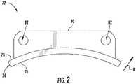
- FIG. 2 is a side view of one embodiment of a shroud block 72 of the gas turbine engine 10.
- several shroud blocks 72 are circumferentially arranged to form a shroud (not shown) enclosing or otherwise surrounding one of the rows of rotor blades 46 in the compressor section 32 or one of the rows of rotor blades 54 in the turbine section 36.
- the shroud block 72 includes an annular wall 74 extending between an inner surface 76 and an outer surface 78 in the radial direction R.
- the inner surface 76 is, in turn, positioned in close proximity to the tips of the corresponding blades 46, 54 to minimize the leakage of the air/combustion gases 68/70 past the blades 46, 54.
- the shroud 72 includes a pair of mounting rails 80 (one is shown).
- the rails 80 are spaced apart from each other in the longitudinal direction L and extend outward from the outer surface 78 of the annular wall 74 in the radial direction R.
- each rail 80 defines a pair of mounting holes 82 for coupling the shroud block 72 to the outer casing 28 of the engine 10.
- the shroud block 72 may have any other suitable configuration.
- one or more the components of the gas turbine engine 10 may be formed of a composite material, such as ceramic matrix composite (CMC) material.
- CMC ceramic matrix composite
- the compressor vanes 44, the compressor blades 46, the turbine vanes 52, the turbine blades 54, and shroud blocks 72 may be formed from CMC materials.
- any other suitable components of the engine 10 may be formed by composite materials.
- gas turbine engine 10 described above and shown in FIGS. 1 and 2 is provided only to place the present subject matter in an exemplary field of use.
- present subject matter may be readily adaptable to any manner of gas turbine engine configuration, including other types of aviation-based gas turbine engines, marine-based gas turbine engines, and/or land-based/industrial gas turbine engines.
- FIG. 3 is a cross-sectional view of one embodiment of a system 100 for infiltrating composite components.
- the system 100 includes a furnace 102 defining a vacuum chamber 104 therein.
- the vacuum chamber 104 is configured to receive a composite component 200 (or a precursor thereto, such as a fiber preform).
- a composite component holder 134 is positioned within the vacuum chamber 104 and configured to receive the composite component 200.
- the composite component holder 134 may be any suitable structure for supporting the composite component 200 during heating and infiltration, such as a platform with a clamping mechanism(s).
- the pressure within the vacuum chamber 104 may be below the ambient pressure (i.e., a vacuum is present within the chamber 104).
- the furnace 102 may be configured to heat the component 200 while the component 200 is under a vacuum pressure.
- the furnace 102 includes one or more heating elements positioned within the vacuum chamber 104 to heat the component 200.
- heating element(s) is configured to heat a first portion of the composite component 200, such as a repair region 202 of the component 200, to a first temperature (e.g., a temperature at or above the melting point of matrix material of the component 200).
- the repair region 202 of the component 200 is positioned on a first portion 136 of the composite component holder 134 such that the first portion 136 and the repair region 202 are heated to the first temperature.
- the heating element(s) is configured to heat a second portion of the composite component 200, such as a non-repair or remaining portion 204 of the component 200, to a different, second temperature (e.g., a lower temperature than the first temperature).
- the remaining portion 204 of the component 200 is positioned on a second portion 138 of the composite component holder 134 such that the second portion 138 and the remaining portion 204 are heated to the second temperature.
- the furnace 102 includes a heating element 106 that surrounds or encloses the component 200.
- the furnace 102 includes a shield 108 positioned between the heating element 106 and the remaining portion 204 of the component 200.
- heat from the heating element 106 is directly transferred (e.g., via radiation) from the heating element 106 to the repair region 202 of the component 200 such that the repair region 202 is heated to the first temperature.
- the shield 108 partially shields or otherwise reduces the amount of heat transferred (e.g., via radiation) from the heating element 108 to the remaining portion 204 of the component 200 such that the remaining portion 204 is heated to the second (e.g., lower) temperature.
- FIG. 4 is a cross-sectional view of another embodiment of a system 100 for infiltrating composite components.
- the system 100 of FIG. 4 includes a furnace 102 defining a vacuum chamber 104 therein, with one or more heating elements positioned within the vacuum chamber 104.
- the system 100 of FIG. 3 includes a heating element 110.
- the composite component 200 is positioned within the vacuum chamber 104 such that the heating element 110 is proximal to the repair region 202 and distal to the remaining portion 204.
- the smaller distance between the heating element 110 and the first portion 202 allows the heating element 110 to heat the repair region 202 to the first temperature.
- the greater distance between the heating element 110 and the remaining portion 204 allows the heating element 110 to heat the remaining portion 204 to the second (e.g., lower) temperature.
- FIG. 5 is a cross-sectional view of a further embodiment of a system 100 for infiltrating composite components.
- the system 100 of FIG. 5 includes a furnace 102 defining a vacuum chamber 104 therein, with one or more heating elements positioned within the vacuum chamber 104.
- the vacuum chamber 104 of the system 100 shown in FIG. 5 includes a plurality of zones. More specifically, as shown, in one embodiment, the vacuum chamber 104 includes first, second, third, and fourth zones 112, 114, 116, 118.
- the zones 112, 114, 116, 118 are separated by baffles or walls 120 such that a portion of the component 200 is exposed to each zone 112, 114, 116, 118.
- the repair region 202 of the component 200 is exposed to the first zone 112 and the remaining portion 204 of the component 200 is exposed to the second, third, and fourth zones 114, 118, 120.
- a heating element 122 is positioned within each zone 112, 114, 116, 118.
- each heating element 122 is of the same type or a mix of heating sources (e.g., resistive carbon heating element, infrared heating lamp element, radio frequency induction coil heating, or on-off gassing heating sources).
- the heating element 122 within the zone 112 operates at a higher power output to heat the repair region 202 of the component 200 to the first temperature.
- the heating elements 122 within the zones 114, 116, 118 operates at a lower power output to heat the remaining portion 204 of the component 200 to the second (e.g., lower) temperature.
- the vacuum chamber 104 may include any other suitable number of zones and/or heating elements with each zone.
- the heating element(s) within each zone may be configured to heat the various portions of the component 200 to any other suitable manner.
- FIG. 6 is a cross-sectional view of yet another embodiment of a system 100 for infiltrating composite components.
- the system 100 of FIG. 6 includes a furnace 102 defining a vacuum chamber 104 therein, with the vacuum chamber 104 including a plurality of zones 112, 114, 116, 118.
- the vacuum chamber 104 of the system 100 of FIG. 6 includes a single heating element 124 extending through each of the zones 112, 114, 116, 118.
- first, second, third, and fourth portions 126, 128, 130, 132 of the heating element 124 are respectively positioned within the first, second, third, and fourth zones 112, 114, 116, 118.
- the first portion 126 of the heating element 124 operates at a higher power output to heat the repair region 202 of the component 200 to the first temperature.
- the second, third, and fourth portions 128, 130, 132 of the heating element 124 operates at a higher power output to heat the remaining portion 204 of the component 200 to the second (e.g., lower) temperature.
- electric current may flow through the first portion 126 of the heating element 124 before flowing through the second, third, and fourth portions 128, 130, 132 of the heating element 124.
- the first portion 126 of the heating element 124 may receive a higher voltage than the second, third, and fourth portions 128, 130, 132 of the heating element 124.
- the heating elements 106, 110, 122, 124 described above may correspond to any suitable type of device for generating heat that can be transferred via radiation to the composite component 200.
- the heating elements 106, 110, 122, 124 are resistive carbon heating elements.
- an infrared heating lamp element generates heat that can heat component 200 via radiation or a radio frequency induction coil can heat component 200 through inductive electrical fields.
- the heating elements 106, 110, 122, 124 described above may heat the composite component 200 in any other suitable manner.
- the heating elements 106, 110, 122, 124 may be configured to heat three or more different portions of the component 200 to three or more different temperatures.
- FIG. 7 is a flow diagram of one embodiment of a method 300 for repairing composite components.
- FIG. 7 depicts steps performed in a particular order, the disclosed methods are not limited to any particular order or arrangement. As such, the various steps of the disclosed methods can be omitted, rearranged, combined, and/or adapted in various ways without deviating from the scope of the present disclosure.
- the composite component 200 may correspond to a composite component of the gas turbine engine 10.
- the composite component 200 may correspond to a compressor vane(s) 44, a compressor blade(s) 46, a turbine vane(s) 52, a turbine blade(s) 54, and/or a shroud block(s) 72 of the engine 10.
- the composite component 200 may correspond to any other suitable composite component.
- FIG. 8 is a perspective view of one embodiment of the composite component 200.
- the composite component 200 includes a repair region 202 and a remaining portion 204. More specifically, the repair region 202 corresponds to a portion of the component 200 that will be repaired in accordance with the methods disclosed herein. As such, the repair region 202 is portion of the component 200 that will be replaced with new composite material. The remaining portion 204 is the portion of the component 200 not being repaired.
- the component 200 shown in FIG. 1 only includes one repair region 202, the component 200 may, in other embodiments, include any other suitable number of repair regions 202.
- the composite component 200 may be formed from any suitable composite material.
- the composite material may be selected from the group consisting of, but not limited to, a ceramic matrix composite (CMC), a polymer matrix composite (PMC), a metal matrix composite (MMC), or a combination thereof.
- a ceramic matrix composite CMC
- PMC polymer matrix composite
- MMC metal matrix composite
- Suitable examples of matrix material for a CMC matrix is ceramic powder, including but not limited to, silicon carbide, aluminum-oxide, silicon oxide, and combinations thereof.
- Suitable examples of matrix material for a PMC include, but are not limited to, epoxy-based matrices, polyester-based matrices, and combinations thereof.
- Suitable examples of a MMC matrix material include, but are not limited to powder metals such as, but not limited to, aluminum or titanium capable of being melted into a continuous molten liquid metal which can encapsulate fibers present in the assembly, before being cooled into a solid ingot with incased fibers.
- the resulting MMC is a metal article with increased stiffness, and the metal portion (matrix) is the primary load caring element.
- the composite component 200 may be formed from a silicon carbide-silicon carbide (SiC-SiC) matrix composite.
- the method 300 includes preparing a repair region of a composite component for repair.
- the worn or damaged material within the repair region 202 that has not already broken off or separated from remaining portion 204 of the composite component 200 may be removed from the component 200 via machining, grinding, cutting, and/or the like.
- the repair region 202 may include an irregular surface 206 unsuitable for joining to the new composite material.
- material from the component 200 may be removed to form a suitable repair interface 208.
- the repair interface 208 is, in turn, the surface of the component 200 to which the new composite material will be joined.
- the worn/damaged material of the repair region 202 has been removed and the repair interface 208 has been formed.
- the method 300 includes positioning repair material within the repair region.
- repair material 210 is positioned within the repair region 202 such that repair material 210 is in contact with the repair interface 208.
- the repair material 210 occupies the space where the worn/damaged material was originally present.
- the repair material 210 will be melt infiltrated within an infiltrant to densify the repair material 210 such that new composite material is formed in the repair region 202, thereby repairing the component 200.
- the repair material 210 corresponds to a precursor material for the composite material from which the component 200 is formed.
- the repair material 210 may include a plurality of fibers defining voids that receive the infiltrant.
- the repair material 210 may correspond to a silicon carbide (SiC) fiber preform having the same shape and size as the void left in the repair region 202.
- the infiltrant may correspond to silicon.
- the repair material 210 may correspond to any other suitable composite precursor material, such as a fiber preform formed of another suitable material, fiber tapes, fiber mats, fiber plies, and the like.
- the method 300 includes placing the composite material within a vacuum chamber.
- the composite component 200 may be placed within the vacuum chamber 104 of the furnace 102.
- the method 300 includes heating the repair region to a first temperature.
- one or more heating elements within the vacuum chamber 104 may heat the repair region 202 of the composite component 200 to a first temperature at or above the melting point of the infiltrant that will densify the repair material 210 (i.e., the matrix material).
- the flow of electric current to the heating element(s) within the vacuum chamber 104 may be controlled (e.g., by an operator or a suitable controller/computing system) such that the heating element(s) heat the repair region 202 to the first temperature.
- the method 300 includes heating a remaining portion of the composite component to a second temperature.
- the heating element(s) within the vacuum chamber 104 e.g., any of the heating elements 106, 110, 122, 124 may heat the remaining portion 204 of the composite component 200 to a second temperature.
- the second temperature is less than the melting point of the infilitrant that will densify the repair material 210 (i.e., the matrix material), but substantially greater than the ambient temperature.
- the second temperature may be less than five hundred degrees Fahrenheit below than the infiltrant melting point, such as less than 250 degrees Fahrenheit or less than one hundred degrees Fahrenheit.
- the flow of electric current to the heating element(s) within the vacuum chamber 104 may be controlled (e.g., by an operator or a suitable controller/computing system) such that the heating element(s) heat the remaining portion 204 to the second temperature.
- Heating the repair region 202 to the first temperature and the remaining portion 204 of the composite component 200 to the second temperature provides one or more technical advantages. More specifically, heating the repair region 202 to the first temperature (i.e., a temperature at or above the melting point of the infiltrant/matrix material) allows the new composite material formed from the repair material 210 within the repair region 202 to fuse with the existing composite material of the component 200. Furthermore, heating the remaining portion 204 of the composite component 200 to the second temperature (i.e., a temperature below the melting point of the infiltrant/matrix material, but substantially above the ambient temperature) allows the existing composite material within the remaining portion 204 to remain solid. Moreover, such heating results in smaller thermal gradients between the repair region 202 and the remaining portion 204 such that stress cracks do not form.
- first temperature i.e., a temperature at or above the melting point of the infiltrant/matrix material
- the method 300 includes melt infiltrating the repair region with an infiltrant to densify the repair material.
- an infiltrant e.g., molten silicon
- FIG. 11 is a flow diagram of one embodiment of a method 400 for infiltrating composite components.
- FIG. 11 depicts steps performed in a particular order, the disclosed methods are not limited to any particular order or arrangement. As such, the various steps of the disclosed methods can be omitted, rearranged, combined, and/or adapted in various ways without deviating from the scope of the present disclosure.
- the method 400 may include heating a first portion of a composite component to a first temperature.
- one or more heating elements within the vacuum chamber 104 e.g., any of the heating elements 106, 110, 122, 124 may heat the repair region 202 of the composite component 200 to a first temperature at or above the melting point of the infiltrant that will densify the repair material 210 (i.e., the matrix material).
- the method 400 includes heating a second portion of the composite component to a second temperature.
- the heating element(s) within the vacuum chamber 104 e.g., any of the heating elements 106, 110, 122, 124) may heat a first section of the remaining portion 204 of the composite component 200 to a second temperature.
- the method 400 includes heating a third portion of the composite component to a third temperature.
- the heating element(s) within the vacuum chamber 104 e.g., any of the heating elements 106, 110, 122, 124) may heat a second section of the remaining portion 204 of the composite component 200 to a third temperature.
- the third temperature is generally below the melting point of infiltrant and may be the different than the second temperature.
- the method 400 includes melt infiltrating the composite component with an infiltrant to densify the first portion of the composite component.
- the repair material 210 is melt infiltrated with a suitable infiltrant (e.g., molten silicon).
- a method for repairing composite components comprising: positioning repair material within a repair region of a composite component formed of a composite material; heating the repair region to a first temperature; heating a remaining portion of the composite component to a second temperature; and melt infiltrating the repair region with an infiltrant to densify the repair material, wherein the first temperature is at or above a melting point of the infiltrant and the second temperature is less than the melting point.
- heating the repair region comprises heating the repair region to the first temperature using a heating element surrounding the composite component; and heating the remaining portion comprises partially shielding the remaining portion from the heating element such that the heating element heats the remaining portion to the second temperature.
- heating the repair region comprises heating the repair region to the first temperature using a heating element; and heating the remaining portion comprises heating the remaining portion to the second temperature using the heating element, the heating element being positioned proximal to the repair region and distal to the remaining portion.
- heating the repair region comprises heating the repair region to the first temperature using a first heating element; and heating the remaining portion comprises heating the remaining portion to the second temperature using a second heating element, the first and second heating elements being of a type of heating element.
- heating the repair region comprises heating the repair region to the first temperature using a first section of a heating element; and heating the remaining portion comprises heating the remaining portion to the second temperature using a second section of the heating element.
- heating the repair region comprises heating the repair region to the first temperature using a carbon heating element.
- repair material comprises silicon carbide and the infiltrant comprises silicon.
- heating the repair region comprises controlling a flow of electric current to one or more heating elements such that the one or more heating elements heat repair region to the first temperature; and heating a remaining portion of the composite component comprises controlling the flow of electric current to the one or more heating elements such that the one or more heating elements heat remaining portion to the second temperature.
- a method of infiltrating composite components comprising: a heating a first portion of a composite component to a first temperature; heating a second portion of the composite component to a second temperature, the second portion being adjacent to the first portion; heating a third portion of the composite component to a third temperature; and melt infiltrating the composite component with an infiltrant to densify the first portion of the composite component, wherein the first temperature is at or above a melting point of the infiltrant and the second and third temperatures are less than the melting point.
- heating the first portion comprises heating the first portion to the first temperature using a heating element surrounding the composite component; and heating the second portion comprises partially shielding the second portion from the heating element such that the heating element heats the second portion to the second temperature.
- heating the first portion comprises heating the first portion to the first temperature using a heating element
- heating the second portion comprises heating the second portion to the second temperature using the heating element, the heating element being positioned proximal to the first portion and distal to the second portion.
- heating the first portion comprises heating the first portion to the first temperature using a first heating element; and heating the second portion comprises heating the second portion to the second temperature using a second heating element, the first and second heating elements being of a type of heating element.
- a system for infiltrating composite components comprising: a furnace defining a vacuum chamber and including a composite component holder positioned within the vacuum chamber, the composite component holder configured to receive a composite component to be infiltrated with an infiltrant; and one or more heating elements positioned within the vacuum chamber, the one or more heating elements configured to heat a first portion of the composite component to a first temperature and heat a second portion of the composite component to a second temperature, wherein the first temperature is at or above a melting point of the infiltrant and the second temperature is less than the melting point.
- the one or more heating elements include a first heating element that surrounds the composite component, the system further comprising: a shield positioned between the first heating element and the second portion to reduce a transfer of heat from the first heating element to the second portion such that the first heating element heats the first portion to the first temperature and the second portion to the second temperature.
- the one or more heating elements include a first heating element positioned proximal to the first portion and distal to the second portion such that the first heating element heats the first portion to the first temperature and the second portion to the second temperature.
- the one or more heating elements include a first heating element configured to heat first portion to the first temperature and a second heating element configured to heat the second portion to the second temperature.
- the one or more heating elements include a first heating element having a first section and a second section, the first section configured to heat the first portion of the composite component to the first temperature and the second section configured to heat the second portion of the composite component to the second temperature.
- the one or more heating elements comprises one or more carbon heating elements.
Landscapes
- Engineering & Computer Science (AREA)
- Chemical & Material Sciences (AREA)
- Mechanical Engineering (AREA)
- Ceramic Engineering (AREA)
- Materials Engineering (AREA)
- General Engineering & Computer Science (AREA)
- Structural Engineering (AREA)
- Organic Chemistry (AREA)
- Chemical Kinetics & Catalysis (AREA)
- Manufacturing & Machinery (AREA)
- Turbine Rotor Nozzle Sealing (AREA)
Abstract
Description
- The present disclosure generally pertains to methods for repairing composite components, such as turbomachine components, and, more specifically, to methods for repairing composite components and associated infiltration systems and methods.
- In recent years, the use of non-traditional high temperature materials, such as ceramic matrix composite (CMC) materials, in gas turbine engines has grown dramatically. Specifically, there is strong interest in replacing metal alloy components within the combustion and turbine sections of a gas turbine engine with CMC components. CMC materials can withstand higher operating temperatures than metal alloys. Higher operating temperatures, in turn, increase the efficiency of the gas turbine engine. Moreover, CMC components require less cooling than metallic components. Additionally, CMC materials are lighter than metallic components and may reduce the structural demands on the engine.
- However, gas turbine components formed from CMC materials can be quite expensive. In this respect, when a CMC gas turbine component becomes worn or damaged, it is desirable to repair, rather than replace, the component. As such, methods of repairing CMC components have been developed. Specifically, the worn or damaged portion(s) of a CMC component may be removed and replaced with new CMC material. In such methods, the entire CMC component is heated to the melting temperature of its matrix material, thereby allowing the new CMC material to fuse with the existing CMC material. Such heating may, however, cause the matrix material of portions of the CMC component not being repaired to liquify and flow out of the component. Conversely, heating only the portion of the CMC component adjacent to the new CMC material to the melting point of the matrix material may result the formation of stress cracks within the component.
- Accordingly, an improved method for repairing composite components would be welcomed in the technology.
- Aspects and advantages of the invention will be set forth in part in the following description, or may be obvious from the description, or may be learned through practice of the invention.
- In one aspect, the present subject matter is directed to a method for repairing composite components. The method includes positioning repair material within a repair region of a composite component formed of a composite material. Furthermore, the method includes heating the repair region to a first temperature. Additionally, the method includes heating a remaining portion of the composite component to a second temperature. Moreover, the method includes melt infiltrating the repair region with an infiltrant to densify the repair material. The first temperature is at or above a melting point of the infiltrant and the second temperature is less than the melting point.
- In another aspect, the present subject matter is directed to a method of infiltrating composite components. The method includes heating a first portion of a composite component to a first temperature. Furthermore, the method includes heating a second portion of the composite component to a second temperature, with the second portion being adjacent to the first portion. Moreover, the method includes heating a third portion of the composite component to a third temperature. Additionally, the method includes melt infiltrating the composite component with an infiltrant to densify the first portion of the composite component. The first temperature is at or above a melting point of the infiltrant and the second and third temperatures are less than the melting point.
- In a further aspect, the present subject matter is directed to a system for infiltrating composite components. The system includes a furnace defining a vacuum chamber and including a composite component holder positioned within the vacuum chamber, with the composite component holder configured to receive a composite component to be infiltrated with an infiltrant. Moreover, the system includes one or more heating elements positioned within the vacuum chamber. The one or more heating elements are, in turn, configured to heat a first portion of the composite component to a first temperature and heat a second portion of the composite component to a second temperature. The first temperature is at or above a melting point of the infiltrant and the second temperature is less than the melting point.
- These and other features, aspects and advantages of the present invention will become better understood with reference to the following description and appended claims. The accompanying drawings, which are incorporated in and constitute a part of this specification, illustrate embodiments of the invention and, together with the description, serve to explain the principles of the invention.
- A full and enabling disclosure of the present invention, including the best mode thereof, directed to one of ordinary skill in the art, is set forth in the specification, which makes reference to the appended figures, in which:
-
FIG. 1 is a schematic cross-sectional view of one embodiment of a gas turbine engine; -
FIG. 2 is a side view of one embodiment of a shroud block of a gas turbine engine; -
FIG. 3 is a cross-sectional view of one embodiment of a system for infiltrating composite components; -
FIG. 4 is a cross-sectional view of another embodiment of a system for infiltrating composite components; -
FIG. 5 is a cross-sectional view of a further embodiment of a system for infiltrating composite components; -
FIG. 6 is a cross-sectional view of yet another embodiment of a system for infiltrating composite components; -
FIG. 7 is a flow diagram of one embodiment of a method for repairing composite components; -
FIG. 8 is a top view of one embodiment of a composite component, particularly illustrating the component prior to repair; -
FIG. 9 is top view of the composite component shown inFIG. 8 , particularly illustrating a repair region of the component after preparation for repair; -
FIG. 10 is a top view of the composite component shown inFIGS. 8 and 9 , particularly illustrating repair material positioned within the repair region; and -
FIG. 11 is a flow diagram of one embodiment of a method for infiltrating composite components. - Repeat use of reference characters in the present specification and drawings is intended to represent the same or analogous features or elements of the present invention.
- Reference now will be made in detail to exemplary embodiments of the presently disclosed subject matter, one or more examples of which are illustrated in the drawings. Each example is provided by way of explanation and should not be interpreted as limiting the present disclosure. In fact, it will be apparent to those skilled in the art that various modifications and variations can be made in the present disclosure without departing from the scope or spirit of the present disclosure. For instance, features illustrated or described as part of one embodiment can be used with another embodiment to yield a still further embodiment. Thus, it is intended that the present disclosure covers such modifications and variations as come within the scope of the appended claims and their equivalents.
- As used herein, the terms "first", "second", and "third" may be used interchangeably to distinguish one component from another and are not intended to signify location or importance of the individual components.
- Furthermore, the terms "upstream" and "downstream" refer to the relative direction with respect to fluid flow in a fluid pathway. For example, "upstream" refers to the direction from which the fluid flows, and "downstream" refers to the direction to which the fluid flows.
- Additionally, the terms "low," "high," or their respective comparative degrees (e.g., lower, higher, where applicable) each refer to relative speeds within an engine, unless otherwise specified. For example, a "low-pressure turbine" operates at a pressure generally lower than a "high-pressure turbine." Alternatively, unless otherwise specified, the aforementioned terms may be understood in their superlative degree. For example, a "low-pressure turbine" may refer to the lowest maximum pressure turbine within a turbine section, and a "high-pressure turbine" may refer to the highest maximum pressure turbine within the turbine section.
- In general, the present subject matter is directed to a method for repairing composite components and associated infiltration methods. In several embodiments, the disclosed methods may be used to repair various turbomachine components, such as ceramic matrix composite (CMC) gas turbine engine blades, vanes, shroud blocks, and/or the like. More specifically, during operation, a composite component may become worn or damaged. As such, in accordance with the disclosed methods, new composite material is formed in place of the worn/damaged portion of the composite component.
- Additionally, the present subject matter is directed to a system for infiltrating composite components. Specifically, in several embodiments, the disclosed system includes a furnace defining a vacuum chamber configured to receive a composite component to be infiltrated with an infiltrant. Furthermore, in such embodiments, the system includes one or more heating elements positioned within the vacuum chamber. The heating element(s), in turn, are configured to heat a first portion of the composite component (e.g., a repair region of the component) to a first temperature at or above the melting point of the infiltrant. Moreover, the heating element(s) are configured to heat a second portion of the composite component (e.g., the remaining portion of the composite component) to a second temperature below the melting point of the infiltrant, but significantly above the ambient temperature.
- In several embodiments, the disclosed methods may be implemented using the disclosed system. More specifically, in one embodiment, the method includes positioning repair material (e.g., fiber plies or a fiber preform) within a repair region of a composite component and placing component within the vacuum chamber. Additionally, the method includes heating the repair region to the first temperature using the one or more heating elements. Moreover, the method includes heating a remaining portion of the composite component to the second temperature using the heating element(s). Thereafter, the method includes melt infiltrating the repair region with the infiltrant to densify the repair material, thereby forming the new composite material within the repair region.
- Heating the repair region to the first temperature and the remaining portion of the composite component to the second temperature provides one or more technical advantages. More specifically, as mentioned above, when repairing a composite component, it is necessary to heat repair region to the melting temperature of the infiltrant/matrix material to allow the new composite material to fuse with the existing composite material. However, heating the entire composite component to the infiltrant melting point may cause infiltrant in the remaining portion to liquify and flow out of the component. Moreover, heating only the repair region may result in the formation of stress cracks within the composite component due to the large thermal gradients existing between the repair region and the remaining portion. In this respect, heating the repair region to the first temperature allows the new composite material to fuse with the existing composite material. Furthermore, heating the remaining portion of the composite component to the second temperature allows the existing composite material within the remaining portion to remain solid, but with smaller thermal gradients between the repair region and the remaining portion such that stress cracks do not form.
- Referring now to the drawings,
FIG. 1 is a schematic cross-sectional view of one embodiment of agas turbine engine 10. In the illustrated embodiment, theengine 10 is configured as a high-bypass turbofan engine. However, in alternative embodiments, theengine 10 may be configured as a propfan engine, a turbojet engine, a turboprop engine, a turboshaft gas turbine engine, or any other suitable type of gas turbine engine. - As shown in
FIG. 1 , theengine 10 defines a longitudinal direction L, a radial direction R, and a circumferential direction C. In general, the longitudinal direction L extends parallel to anaxial centerline 12 of theengine 10, the radial direction R extends orthogonally outward from theaxial centerline 12, and the circumferential direction C extends generally concentrically around theaxial centerline 12. - In general, the
engine 10 includes afan 14, a low-pressure (LP)spool 16, and a high pressure (HP)spool 18 at least partially encased by anannular nacelle 20. More specifically, thefan 14 may include afan rotor 22 and a plurality of fan blades 24 (one is shown) coupled to thefan rotor 22. In this respect, thefan blades 24 are spaced apart from each other along the circumferential direction C and extend outward from thefan rotor 22 along the radial direction R. Moreover, the LP and HP spools 16, 18 are positioned downstream from thefan 14 along the axial centerline 12 (i.e., in the longitudinal direction L). As shown, theLP spool 16 is rotatably coupled to thefan rotor 22, thereby permitting theLP spool 16 to rotate thefan 14. Additionally, a plurality of outlet guide vanes or struts 26 spaced apart from each other in the circumferential direction C extend between anouter casing 28 surrounding the LP and HP spools 16, 18 and thenacelle 20 along the radial direction R. As such, thestruts 26 support thenacelle 20 relative to theouter casing 28 such that theouter casing 28 and thenacelle 20 define abypass airflow passage 30 positioned therebetween. - The
outer casing 28 generally surrounds or encases, in serial flow order, acompressor section 32, acombustion section 34, aturbine section 36, and anexhaust section 38. For example, in some embodiments, thecompressor section 32 may include a low-pressure (LP)compressor 40 of theLP spool 16 and a high-pressure (HP)compressor 42 of theHP spool 18 positioned downstream from theLP compressor 40 along theaxial centerline 12. Eachcompressor stator vanes 44 interdigitated with one or more rows ofcompressor rotor blades 46. Moreover, in some embodiments, theturbine section 36 includes a high-pressure (HP)turbine 48 of theHP spool 18 and a low-pressure (LP)turbine 50 of theLP spool 16 positioned downstream from theHP turbine 48 along theaxial centerline 12. Eachturbine stator vanes 52 interdigitated with one or more rows ofturbine rotor blades 54. - Additionally, the
LP spool 16 includes the low-pressure (LP)shaft 56 and theHP spool 18 includes a high pressure (HP)shaft 58 positioned concentrically around theLP shaft 56. In such embodiments, theHP shaft 58 rotatably couples therotor blades 54 of theHP turbine 48 and therotor blades 46 of theHP compressor 42 such that rotation of the HPturbine rotor blades 54 rotatably drives HPcompressor rotor blades 46. As shown, theLP shaft 56 is directly coupled to therotor blades 54 of theLP turbine 50 and therotor blades 46 of theLP compressor 40. Furthermore, theLP shaft 56 is coupled to thefan 14 via agearbox 60. In this respect, the rotation of the LPturbine rotor blades 54 rotatably drives the LPcompressor rotor blades 46 and thefan blades 24. - In several embodiments, the
engine 10 may generate thrust to propel an aircraft. More specifically, during operation, air (indicated by arrow 62) enters aninlet portion 64 of theengine 10. Thefan 14 supplies a first portion (indicated by arrow 66) of theair 62 to thebypass airflow passage 30 and a second portion (indicated by arrow 68) of theair 62 to thecompressor section 32. Thesecond portion 68 of theair 62 first flows through theLP compressor 40 in which therotor blades 46 therein progressively compress thesecond portion 68 of theair 62. Next, thesecond portion 68 of theair 62 flows through theHP compressor 42 in which therotor blades 46 therein continue progressively compressing thesecond portion 68 of theair 62. The compressedsecond portion 68 of theair 62 is subsequently delivered to thecombustion section 34. In thecombustion section 34, thesecond portion 68 of theair 62 mixes with fuel and burns to generate high-temperature and high-pressure combustion gases 70. Thereafter, thecombustion gases 70 flow through theHP turbine 48 which the HPturbine rotor blades 54 extract a first portion of kinetic and/or thermal energy therefrom. This energy extraction rotates theHP shaft 58, thereby driving theHP compressor 42. Thecombustion gases 70 then flow through theLP turbine 50 in which the LPturbine rotor blades 54 extract a second portion of kinetic and/or thermal energy therefrom. This energy extraction rotates theLP shaft 56, thereby driving theLP compressor 40 and thefan 14 via thegearbox 60. Thecombustion gases 70 then exit theengine 10 through theexhaust section 38. -
FIG. 2 is a side view of one embodiment of ashroud block 72 of thegas turbine engine 10. In general, several shroud blocks 72 are circumferentially arranged to form a shroud (not shown) enclosing or otherwise surrounding one of the rows ofrotor blades 46 in thecompressor section 32 or one of the rows ofrotor blades 54 in theturbine section 36. As shown, theshroud block 72 includes anannular wall 74 extending between aninner surface 76 and anouter surface 78 in the radial direction R. Theinner surface 76 is, in turn, positioned in close proximity to the tips of thecorresponding blades combustion gases 68/70 past theblades shroud 72 includes a pair of mounting rails 80 (one is shown). Therails 80 are spaced apart from each other in the longitudinal direction L and extend outward from theouter surface 78 of theannular wall 74 in the radial direction R. Moreover, eachrail 80 defines a pair of mountingholes 82 for coupling theshroud block 72 to theouter casing 28 of theengine 10. However, in alternative embodiments, theshroud block 72 may have any other suitable configuration. - Additionally, one or more the components of the
gas turbine engine 10 may be formed of a composite material, such as ceramic matrix composite (CMC) material. For example, in several embodiments, thecompressor vanes 44, thecompressor blades 46, theturbine vanes 52, theturbine blades 54, and shroud blocks 72 may be formed from CMC materials. However, in alternative embodiments, any other suitable components of theengine 10 may be formed by composite materials. - The configuration of the
gas turbine engine 10 described above and shown inFIGS. 1 and2 is provided only to place the present subject matter in an exemplary field of use. Thus, the present subject matter may be readily adaptable to any manner of gas turbine engine configuration, including other types of aviation-based gas turbine engines, marine-based gas turbine engines, and/or land-based/industrial gas turbine engines. -
FIG. 3 is a cross-sectional view of one embodiment of asystem 100 for infiltrating composite components. As shown, thesystem 100 includes afurnace 102 defining avacuum chamber 104 therein. Thevacuum chamber 104, in turn, is configured to receive a composite component 200 (or a precursor thereto, such as a fiber preform). Specifically, in several embodiments, acomposite component holder 134 is positioned within thevacuum chamber 104 and configured to receive thecomposite component 200. As such, thecomposite component holder 134 may be any suitable structure for supporting thecomposite component 200 during heating and infiltration, such as a platform with a clamping mechanism(s). During operation of thefurnace 102, the pressure within thevacuum chamber 104 may be below the ambient pressure (i.e., a vacuum is present within the chamber 104). In this respect, thefurnace 102 may be configured to heat thecomponent 200 while thecomponent 200 is under a vacuum pressure. - In general, the
furnace 102 includes one or more heating elements positioned within thevacuum chamber 104 to heat thecomponent 200. Specifically, heating element(s) is configured to heat a first portion of thecomposite component 200, such as arepair region 202 of thecomponent 200, to a first temperature (e.g., a temperature at or above the melting point of matrix material of the component 200). In several embodiments, therepair region 202 of thecomponent 200 is positioned on afirst portion 136 of thecomposite component holder 134 such that thefirst portion 136 and therepair region 202 are heated to the first temperature. Moreover, the heating element(s) is configured to heat a second portion of thecomposite component 200, such as a non-repair or remainingportion 204 of thecomponent 200, to a different, second temperature (e.g., a lower temperature than the first temperature). In several embodiments, the remainingportion 204 of thecomponent 200 is positioned on asecond portion 138 of thecomposite component holder 134 such that thesecond portion 138 and the remainingportion 204 are heated to the second temperature. As such, in the illustrated embodiment, thefurnace 102 includes aheating element 106 that surrounds or encloses thecomponent 200. Furthermore, in the illustrated embodiment, thefurnace 102 includes ashield 108 positioned between theheating element 106 and the remainingportion 204 of thecomponent 200. In this respect, during operation, heat from theheating element 106 is directly transferred (e.g., via radiation) from theheating element 106 to therepair region 202 of thecomponent 200 such that therepair region 202 is heated to the first temperature. Additionally, theshield 108 partially shields or otherwise reduces the amount of heat transferred (e.g., via radiation) from theheating element 108 to the remainingportion 204 of thecomponent 200 such that the remainingportion 204 is heated to the second (e.g., lower) temperature. -
FIG. 4 is a cross-sectional view of another embodiment of asystem 100 for infiltrating composite components. Like the embodiment of thesystem 100 shown inFIG. 3 , thesystem 100 ofFIG. 4 includes afurnace 102 defining avacuum chamber 104 therein, with one or more heating elements positioned within thevacuum chamber 104. However, unlike the embodiment shown inFIG. 3 , thesystem 100 ofFIG. 3 includes aheating element 110. Specifically, during operation, thecomposite component 200 is positioned within thevacuum chamber 104 such that theheating element 110 is proximal to therepair region 202 and distal to the remainingportion 204. In this respect, the smaller distance between theheating element 110 and thefirst portion 202 allows theheating element 110 to heat therepair region 202 to the first temperature. Conversely, the greater distance between theheating element 110 and the remainingportion 204 allows theheating element 110 to heat the remainingportion 204 to the second (e.g., lower) temperature. -
FIG. 5 is a cross-sectional view of a further embodiment of asystem 100 for infiltrating composite components. Like the embodiments of thesystem 100 shown inFIGS. 3 and 4 , thesystem 100 ofFIG. 5 includes afurnace 102 defining avacuum chamber 104 therein, with one or more heating elements positioned within thevacuum chamber 104. However, unlike the embodiments shown inFIGS. 3 and 4 , thevacuum chamber 104 of thesystem 100 shown inFIG. 5 includes a plurality of zones. More specifically, as shown, in one embodiment, thevacuum chamber 104 includes first, second, third, andfourth zones zones walls 120 such that a portion of thecomponent 200 is exposed to eachzone repair region 202 of thecomponent 200 is exposed to thefirst zone 112 and the remainingportion 204 of thecomponent 200 is exposed to the second, third, andfourth zones heating element 122 is positioned within eachzone heating element 122 is of the same type or a mix of heating sources (e.g., resistive carbon heating element, infrared heating lamp element, radio frequency induction coil heating, or on-off gassing heating sources). During operation, theheating element 122 within thezone 112 operates at a higher power output to heat therepair region 202 of thecomponent 200 to the first temperature. Conversely, theheating elements 122 within thezones portion 204 of thecomponent 200 to the second (e.g., lower) temperature. However, in alternative embodiments, thevacuum chamber 104 may include any other suitable number of zones and/or heating elements with each zone. Furthermore, the heating element(s) within each zone may be configured to heat the various portions of thecomponent 200 to any other suitable manner. -
FIG. 6 is a cross-sectional view of yet another embodiment of asystem 100 for infiltrating composite components. Like the embodiments of thesystem 100 shown inFIG. 5 , thesystem 100 ofFIG. 6 includes afurnace 102 defining avacuum chamber 104 therein, with thevacuum chamber 104 including a plurality ofzones FIG. 5 , thevacuum chamber 104 of thesystem 100 ofFIG. 6 includes asingle heating element 124 extending through each of thezones fourth portions heating element 124 are respectively positioned within the first, second, third, andfourth zones first portion 126 of theheating element 124 operates at a higher power output to heat therepair region 202 of thecomponent 200 to the first temperature. Conversely, the second, third, andfourth portions heating element 124 operates at a higher power output to heat the remainingportion 204 of thecomponent 200 to the second (e.g., lower) temperature. For example, in such instances, electric current may flow through thefirst portion 126 of theheating element 124 before flowing through the second, third, andfourth portions heating element 124. As such, thefirst portion 126 of theheating element 124 may receive a higher voltage than the second, third, andfourth portions heating element 124. - The
heating elements composite component 200. For example, in several embodiments, theheating elements heating elements component 200. In other embodiments, an infrared heating lamp element generates heat that can heatcomponent 200 via radiation or a radio frequency induction coil can heatcomponent 200 through inductive electrical fields. - Additionally, the
heating elements composite component 200 in any other suitable manner. For example, in one embodiment, theheating elements component 200 to three or more different temperatures. - The configurations of the
system 100 described above and shown inFIG. 3-6 is provided only to place the present subject matter in an exemplary field of use. Thus, the present subject matter may be readily adaptable to any manner of system for infiltrating composite components. -
FIG. 7 is a flow diagram of one embodiment of amethod 300 for repairing composite components. AlthoughFIG. 7 depicts steps performed in a particular order, the disclosed methods are not limited to any particular order or arrangement. As such, the various steps of the disclosed methods can be omitted, rearranged, combined, and/or adapted in various ways without deviating from the scope of the present disclosure. - In general, the various steps of the
method 300 will be described below in the context of repairing acomposite component 200. For example, as will be described below, thecomposite component 200 may correspond to a composite component of thegas turbine engine 10. For example, in some embodiments, thecomposite component 200 may correspond to a compressor vane(s) 44, a compressor blade(s) 46, a turbine vane(s) 52, a turbine blade(s) 54, and/or a shroud block(s) 72 of theengine 10. However, in alternative embodiments, thecomposite component 200 may correspond to any other suitable composite component. -
FIG. 8 is a perspective view of one embodiment of thecomposite component 200. As shown, thecomposite component 200 includes arepair region 202 and a remainingportion 204. More specifically, therepair region 202 corresponds to a portion of thecomponent 200 that will be repaired in accordance with the methods disclosed herein. As such, therepair region 202 is portion of thecomponent 200 that will be replaced with new composite material. The remainingportion 204 is the portion of thecomponent 200 not being repaired. Although thecomponent 200 shown inFIG. 1 only includes onerepair region 202, thecomponent 200 may, in other embodiments, include any other suitable number ofrepair regions 202. - Moreover, the
composite component 200 may be formed from any suitable composite material. For example, the composite material may be selected from the group consisting of, but not limited to, a ceramic matrix composite (CMC), a polymer matrix composite (PMC), a metal matrix composite (MMC), or a combination thereof. Suitable examples of matrix material for a CMC matrix is ceramic powder, including but not limited to, silicon carbide, aluminum-oxide, silicon oxide, and combinations thereof. Suitable examples of matrix material for a PMC include, but are not limited to, epoxy-based matrices, polyester-based matrices, and combinations thereof. Suitable examples of a MMC matrix material include, but are not limited to powder metals such as, but not limited to, aluminum or titanium capable of being melted into a continuous molten liquid metal which can encapsulate fibers present in the assembly, before being cooled into a solid ingot with incased fibers. The resulting MMC is a metal article with increased stiffness, and the metal portion (matrix) is the primary load caring element. For example, in one embodiment, thecomposite component 200 may be formed from a silicon carbide-silicon carbide (SiC-SiC) matrix composite. - Referring again to
FIG. 7 , at (302), themethod 300 includes preparing a repair region of a composite component for repair. Specifically, in several embodiments, at (302), the worn or damaged material within therepair region 202 that has not already broken off or separated from remainingportion 204 of thecomposite component 200 may be removed from thecomponent 200 via machining, grinding, cutting, and/or the like. For example, in certain instances, as shown inFIG. 4 , therepair region 202 may include anirregular surface 206 unsuitable for joining to the new composite material. In such instances, at (302), material from thecomponent 200 may be removed to form asuitable repair interface 208. Therepair interface 208 is, in turn, the surface of thecomponent 200 to which the new composite material will be joined. As shown inFIG. 9 , upon completion of (302), the worn/damaged material of therepair region 202 has been removed and therepair interface 208 has been formed. - Additionally, as shown in
FIG. 7 , after preparing the repair region, at (304), themethod 300 includes positioning repair material within the repair region. For example, as shown inFIG. 10 ,repair material 210 is positioned within therepair region 202 such thatrepair material 210 is in contact with therepair interface 208. In this respect, therepair material 210 occupies the space where the worn/damaged material was originally present. As will be described below, therepair material 210 will be melt infiltrated within an infiltrant to densify therepair material 210 such that new composite material is formed in therepair region 202, thereby repairing thecomponent 200. - In general, the
repair material 210 corresponds to a precursor material for the composite material from which thecomponent 200 is formed. As such, therepair material 210 may include a plurality of fibers defining voids that receive the infiltrant. For example, in embodiments in which thecomponent 200 is formed from a SiC-SiC matrix composite, therepair material 210 may correspond to a silicon carbide (SiC) fiber preform having the same shape and size as the void left in therepair region 202. In such embodiments, the infiltrant may correspond to silicon. However, in alternative embodiments, therepair material 210 may correspond to any other suitable composite precursor material, such as a fiber preform formed of another suitable material, fiber tapes, fiber mats, fiber plies, and the like. - Furthermore, as shown in
FIG. 7 , at (306), themethod 300 includes placing the composite material within a vacuum chamber. For example, after positioning therepair material 210 within therepair region 202, thecomposite component 200 may be placed within thevacuum chamber 104 of thefurnace 102. - Moreover, at (308), the
method 300 includes heating the repair region to a first temperature. For example, one or more heating elements within the vacuum chamber 104 (e.g., any of theheating elements repair region 202 of thecomposite component 200 to a first temperature at or above the melting point of the infiltrant that will densify the repair material 210 (i.e., the matrix material). In several embodiments, the flow of electric current to the heating element(s) within thevacuum chamber 104 may be controlled (e.g., by an operator or a suitable controller/computing system) such that the heating element(s) heat therepair region 202 to the first temperature. - In addition, as shown in
FIG. 7 , at (310), themethod 300 includes heating a remaining portion of the composite component to a second temperature. For example, the heating element(s) within the vacuum chamber 104 (e.g., any of theheating elements portion 204 of thecomposite component 200 to a second temperature. The second temperature, in turn, is less than the melting point of the infilitrant that will densify the repair material 210 (i.e., the matrix material), but substantially greater than the ambient temperature. For example, the second temperature may be less than five hundred degrees Fahrenheit below than the infiltrant melting point, such as less than 250 degrees Fahrenheit or less than one hundred degrees Fahrenheit. In some embodiments, the flow of electric current to the heating element(s) within thevacuum chamber 104 may be controlled (e.g., by an operator or a suitable controller/computing system) such that the heating element(s) heat the remainingportion 204 to the second temperature. - Heating the
repair region 202 to the first temperature and the remainingportion 204 of thecomposite component 200 to the second temperature provides one or more technical advantages. More specifically, heating therepair region 202 to the first temperature (i.e., a temperature at or above the melting point of the infiltrant/matrix material) allows the new composite material formed from therepair material 210 within therepair region 202 to fuse with the existing composite material of thecomponent 200. Furthermore, heating the remainingportion 204 of thecomposite component 200 to the second temperature (i.e., a temperature below the melting point of the infiltrant/matrix material, but substantially above the ambient temperature) allows the existing composite material within the remainingportion 204 to remain solid. Moreover, such heating results in smaller thermal gradients between therepair region 202 and the remainingportion 204 such that stress cracks do not form. - Further, after heating the repair region to the first temperature and the remaining portion to the second temperature, at (312), the
method 300 includes melt infiltrating the repair region with an infiltrant to densify the repair material. For example, after therepair region 202 is heated to the first temperature and the remainingportion 204 is heated to the second temperature, therepair material 210 is melt infiltrated with a suitable infiltrant (e.g., molten silicon). -
FIG. 11 is a flow diagram of one embodiment of amethod 400 for infiltrating composite components. AlthoughFIG. 11 depicts steps performed in a particular order, the disclosed methods are not limited to any particular order or arrangement. As such, the various steps of the disclosed methods can be omitted, rearranged, combined, and/or adapted in various ways without deviating from the scope of the present disclosure. - As shown in
FIG. 11 , at (402), themethod 400 may include heating a first portion of a composite component to a first temperature. For example, as described above, one or more heating elements within the vacuum chamber 104 (e.g., any of theheating elements repair region 202 of thecomposite component 200 to a first temperature at or above the melting point of the infiltrant that will densify the repair material 210 (i.e., the matrix material). - Additionally, at (404), the
method 400 includes heating a second portion of the composite component to a second temperature. For example, the heating element(s) within the vacuum chamber 104 (e.g., any of theheating elements portion 204 of thecomposite component 200 to a second temperature. - Furthermore, at (406), the
method 400 includes heating a third portion of the composite component to a third temperature. For example, the heating element(s) within the vacuum chamber 104 (e.g., any of theheating elements portion 204 of thecomposite component 200 to a third temperature. The third temperature is generally below the melting point of infiltrant and may be the different than the second temperature. - Moreover, after heating the repair region to the first temperature and the remaining portion to the second temperature, at (408), the
method 400 includes melt infiltrating the composite component with an infiltrant to densify the first portion of the composite component. For example, after therepair region 202 is heated to the first temperature and the remainingportion 204 is heated to the second temperature, therepair material 210 is melt infiltrated with a suitable infiltrant (e.g., molten silicon). - This written description uses examples to disclose the invention, including the best mode, and also to enable any person skilled in the art to practice the invention, including making and using any devices or systems and performing any incorporated methods. The patentable scope of the invention is defined by the claims, and may include other examples that occur to those skilled in the art. Such other examples are intended to be within the scope of the claims if they include structural elements that do not differ from the literal language of the claims, or if they include equivalent structural elements with insubstantial differences from the literal language of the claims.
- Further aspects of the invention are provided by the subject matter of the following clauses:
- A method for repairing composite components, the method comprising: positioning repair material within a repair region of a composite component formed of a composite material; heating the repair region to a first temperature; heating a remaining portion of the composite component to a second temperature; and melt infiltrating the repair region with an infiltrant to densify the repair material, wherein the first temperature is at or above a melting point of the infiltrant and the second temperature is less than the melting point.
- The method of one or more of these clauses, wherein: heating the repair region comprises heating the repair region to the first temperature using a heating element surrounding the composite component; and heating the remaining portion comprises partially shielding the remaining portion from the heating element such that the heating element heats the remaining portion to the second temperature.
- The method of one or more of these clauses, wherein: heating the repair region comprises heating the repair region to the first temperature using a heating element; and heating the remaining portion comprises heating the remaining portion to the second temperature using the heating element, the heating element being positioned proximal to the repair region and distal to the remaining portion.
- The method of one or more of these clauses, wherein: heating the repair region comprises heating the repair region to the first temperature using a first heating element; and heating the remaining portion comprises heating the remaining portion to the second temperature using a second heating element, the first and second heating elements being of a type of heating element.
- The method of one or more of these clauses, wherein: heating the repair region comprises heating the repair region to the first temperature using a first section of a heating element; and heating the remaining portion comprises heating the remaining portion to the second temperature using a second section of the heating element.
- The method of one or more of these clauses, further comprising: placing the composite component within a vacuum chamber before heating the repair region and heating the remaining portion.
- The method of one or more of these clauses, wherein heating the repair region comprises heating the repair region to the first temperature using a carbon heating element.
- The method of one or more of these clauses, wherein the repair material comprises silicon carbide and the infiltrant comprises silicon.
- The method of one or more of these clauses, wherein: heating the repair region comprises controlling a flow of electric current to one or more heating elements such that the one or more heating elements heat repair region to the first temperature; and heating a remaining portion of the composite component comprises controlling the flow of electric current to the one or more heating elements such that the one or more heating elements heat remaining portion to the second temperature.
- A method of infiltrating composite components, the method comprising: a heating a first portion of a composite component to a first temperature; heating a second portion of the composite component to a second temperature, the second portion being adjacent to the first portion; heating a third portion of the composite component to a third temperature; and melt infiltrating the composite component with an infiltrant to densify the first portion of the composite component, wherein the first temperature is at or above a melting point of the infiltrant and the second and third temperatures are less than the melting point.
- The method of one or more of these clauses, wherein: heating the first portion comprises heating the first portion to the first temperature using a heating element surrounding the composite component; and heating the second portion comprises partially shielding the second portion from the heating element such that the heating element heats the second portion to the second temperature.
- The method of one or more of these clauses, wherein: heating the first portion comprises heating the first portion to the first temperature using a heating element; and heating the second portion comprises heating the second portion to the second temperature using the heating element, the heating element being positioned proximal to the first portion and distal to the second portion.
- The method of one or more of these clauses, wherein: heating the first portion comprises heating the first portion to the first temperature using a first heating element; and heating the second portion comprises heating the second portion to the second temperature using a second heating element, the first and second heating elements being of a type of heating element.
- A system for infiltrating composite components, the system comprising: a furnace defining a vacuum chamber and including a composite component holder positioned within the vacuum chamber, the composite component holder configured to receive a composite component to be infiltrated with an infiltrant; and one or more heating elements positioned within the vacuum chamber, the one or more heating elements configured to heat a first portion of the composite component to a first temperature and heat a second portion of the composite component to a second temperature, wherein the first temperature is at or above a melting point of the infiltrant and the second temperature is less than the melting point.
- The system of one or more of these clauses, wherein the one or more heating elements include a first heating element that surrounds the composite component, the system further comprising: a shield positioned between the first heating element and the second portion to reduce a transfer of heat from the first heating element to the second portion such that the first heating element heats the first portion to the first temperature and the second portion to the second temperature.
- The system of one or more of these clauses, wherein the one or more heating elements include a first heating element positioned proximal to the first portion and distal to the second portion such that the first heating element heats the first portion to the first temperature and the second portion to the second temperature.
- The system of one or more of these clauses, wherein the one or more heating elements include a first heating element configured to heat first portion to the first temperature and a second heating element configured to heat the second portion to the second temperature.
- The system of one or more of these clauses, wherein the first and second heating elements are of a same type of heating element.
- The system of one or more of these clauses, wherein the one or more heating elements include a first heating element having a first section and a second section, the first section configured to heat the first portion of the composite component to the first temperature and the second section configured to heat the second portion of the composite component to the second temperature.
- The system of one or more of these clauses, wherein the one or more heating elements comprises one or more carbon heating elements.
Claims (15)
- A method (300) for repairing composite components, the method (300) comprising:positioning repair material (210) within a repair region (202) of a composite component (200) formed of a composite material;heating the repair region (202) to a first temperature;heating a remaining portion (204) of the composite component (200) to a second temperature; andmelt infiltrating the repair region (202) with an infiltrant to densify the repair material (210),wherein the first temperature is at or above a melting point of the infiltrant and the second temperature is less than the melting point.
- The method (300) of any preceding claim, wherein:heating the repair region (202) comprises heating the repair region (202) to the first temperature using a heating element (106) surrounding the composite component (200); andheating the remaining portion (204) comprises partially shielding the remaining portion (204) from the heating element (106) such that the heating element (106) heats the remaining portion (204) to the second temperature.
- The method (300) of any preceding claim, wherein:heating the repair region (202) comprises heating the repair region (202) to the first temperature using a heating element (106); andheating the remaining portion (204) comprises heating the remaining portion (204) to the second temperature using the heating element (106), the heating element (106) being positioned proximal to the repair region (202) and distal to the remaining portion (204).
- The method (300) of any preceding claim, wherein:heating the repair region (202) comprises heating the repair region (202) to the first temperature using a first heating element (106); andheating the remaining portion (204) comprises heating the remaining portion (204) to the second temperature using a second heating element (106), the first and second heating elements (106) being of a type of heating element (106).
- The method (300) of any preceding claim, wherein:heating the repair region (202) comprises heating the repair region (202) to the first temperature using a first section of a heating element (106); andheating the remaining portion (204) comprises heating the remaining portion (204) to the second temperature using a second section of the heating element (106).
- The method (300) of any preceding claim, further comprising:
placing the composite component (200) within a vacuum chamber (104) before heating the repair region (202) and heating the remaining portion (204). - The method (300) of any preceding claim, wherein heating the repair region (202) comprises heating the repair region (202) to the first temperature using a carbon heating element (106).
- The method (300) of any preceding claim, wherein the repair material (210) comprises silicon carbide and the infiltrant comprises silicon.
- The method (300) of any preceding claim, further comprising:
preparing the repair region (202) for repair before positioning the repair material (210) within the repair region (202). - A method (300) of infiltrating composite components, the method (300) comprising:heating a first portion (126) of a composite component (200) to a first temperature;heating a second portion (68) of the composite component (200) to a second temperature; andmelt infiltrating the composite component (200) with an infiltrant to densify the first portion (126) of the composite component (200),wherein the first temperature is at or above a melting point of the infiltrant and the second temperature is less than the melting point.
- A system (100) for infiltrating composite components, the system (100) comprising:a furnace (102) defining a vacuum chamber (104) configured to receive a composite component (200) to be infiltrated with an infiltrant; andone or more heating elements (106) positioned within the vacuum chamber (104), the one or more heating elements (106) configured to heat a first portion (126) of the composite component (200) to a first temperature and heat a second portion (68) of the composite component (200) to a second temperature,wherein the first temperature is at or above a melting point of the infiltrant and the second temperature is less than the melting point.
- The system (100) of any preceding claim, wherein the one or more heating elements (106) include a first heating element (106) that surrounds the composite component (200), the system (100) further comprising:
a shield (108) positioned between the first heating element (106) and the second portion (68) to reduce a transfer of heat from the first heating element (106) to the second portion (68) such that the first heating element (106) heats the first portion (126) to the first temperature and the second portion (68) to the second temperature. - The system (100) of any preceding claim, wherein the one or more heating elements (106) include a first heating element (106) positioned proximal to the first portion (126) and distal to the second portion (68) such that the first heating element (106) heats the first portion (126) to the first temperature and the second portion (68) to the second temperature.
- The system (100) of any preceding claim, wherein the one or more heating elements (106) include a first heating element (106) configured to heat first portion (126) to the first temperature and a second heating element (106) configured to heat the second portion (68) to the second temperature.
- The system (100) of any preceding claim, wherein the one or more heating elements (106) include a first heating element (106) having a first section and a second section, the first section configured to heat the first portion (126) of the composite component (200) to the first temperature and the second section configured to heat the second portion (68) of the composite component (200) to the second temperature.
Applications Claiming Priority (1)
| Application Number | Priority Date | Filing Date | Title |
|---|---|---|---|
| US17/032,035 US11969962B2 (en) | 2020-09-25 | 2020-09-25 | Method for repairing composite components and associated infiltration systems and methods |
Publications (1)
| Publication Number | Publication Date |
|---|---|
| EP3974404A1 true EP3974404A1 (en) | 2022-03-30 |
Family
ID=77518995
Family Applications (1)
| Application Number | Title | Priority Date | Filing Date |
|---|---|---|---|
| EP21193237.1A Pending EP3974404A1 (en) | 2020-09-25 | 2021-08-26 | Method for repairing composite components and associated infiltration systems and methods |
Country Status (3)
| Country | Link |
|---|---|
| US (1) | US11969962B2 (en) |
| EP (1) | EP3974404A1 (en) |
| CN (1) | CN114251127B (en) |
Cited By (1)
| Publication number | Priority date | Publication date | Assignee | Title |
|---|---|---|---|---|
| CN117567168A (en) * | 2023-11-30 | 2024-02-20 | 郑州磨料磨具磨削研究所有限公司 | A method for connecting silicon carbide ceramic components and blanks |
Citations (5)
| Publication number | Priority date | Publication date | Assignee | Title |
|---|---|---|---|---|
| US20130022471A1 (en) * | 2011-07-22 | 2013-01-24 | General Electric Company | Methods for repairing a turbine airfoil constructed from cmc material |
| US9366140B2 (en) * | 2013-03-15 | 2016-06-14 | Rolls-Royce Corporation | Ceramic matrix composite repair by reactive processing and mechanical interlocking |
| US20160175960A1 (en) * | 2014-12-22 | 2016-06-23 | Rolls-Royce High Temperature Composites, Inc. | Method for making ceramic matrix composite articles with progressive melt infiltration |
| US20180094525A1 (en) * | 2016-10-04 | 2018-04-05 | General Electric Company | Methods and features for cmc component repairs |
| RU2682902C2 (en) * | 2014-03-14 | 2019-03-22 | Сафран Серамикс | Cvi densification equipment including high-capability preheating area |
Family Cites Families (22)
| Publication number | Priority date | Publication date | Assignee | Title |
|---|---|---|---|---|
| US1943802A (en) | 1930-03-18 | 1934-01-16 | Ajax Electrothermic Corp | Electric induction furnace |
| US4611744A (en) * | 1982-06-23 | 1986-09-16 | Refurbished Turbine Components Ltd. | Turbine blade repair |
| US4845332A (en) | 1987-09-16 | 1989-07-04 | National Steel Corp. | Galvanneal induction furnace temperature control system |
| US5266236A (en) | 1991-10-09 | 1993-11-30 | General Electric Company | Thermally stable dense electrically conductive diamond compacts |
| US6820334B2 (en) * | 2002-04-19 | 2004-11-23 | General Electric Company | Method for repairing articles of ceramic composites |
| US8884201B2 (en) | 2008-09-15 | 2014-11-11 | The Boeing Company | Systems and methods for fabrication of thermoplastic components |
| DE102010031795B4 (en) | 2010-07-20 | 2015-05-28 | Lufthansa Technik Ag | Method for repairing gas turbine components made of ceramic composite materials and apparatus for carrying out the method |
| WO2014150936A1 (en) | 2013-03-15 | 2014-09-25 | Lazur Andrew J | Melt infiltration apparatus and method for molten metal control |
| US9598321B2 (en) | 2013-03-15 | 2017-03-21 | Rolls-Royce Corporation | Melt infiltration wick attachment |
| US9512044B2 (en) | 2013-03-15 | 2016-12-06 | Rolls-Royce Corporation | Ceramic matrix composites and methods for producing ceramic matrix composites |
| WO2015148362A1 (en) * | 2014-03-24 | 2015-10-01 | Rtr Technologies, Inc. | Radiant heating system for a surface structure, and surface structure assembly with radiant heater |
| US9624138B2 (en) | 2014-04-08 | 2017-04-18 | United Technologies Corporation | Formation of voids within components formed from porous substrates |
| US20150291473A1 (en) | 2014-04-09 | 2015-10-15 | United Technologies Corporation | Energy preparation of ceramic fiber for coating |
| US10293424B2 (en) | 2015-05-05 | 2019-05-21 | Rolls-Royce Corporation | Braze for ceramic and ceramic matrix composite components |
| US10150708B2 (en) | 2015-05-08 | 2018-12-11 | Rolls-Royce High Temperature Composites Inc. | Surface-aided melt infiltration for producing a ceramic matrix composite |
| DE102016207233A1 (en) * | 2016-04-28 | 2017-11-02 | Fraunhofer-Gesellschaft zur Förderung der angewandten Forschung e.V. | A method for locally forming a smooth surface of a substrate made of glass or a glass ceramic as well as a control element produced by the method |
| US10144675B2 (en) | 2016-10-24 | 2018-12-04 | Honeywell International Inc. | Segmented carbon fiber preform |
| US10150188B1 (en) * | 2017-08-04 | 2018-12-11 | General Electric Company | Method of ceramic matrix composite repair |
| WO2019112662A1 (en) * | 2017-12-05 | 2019-06-13 | Siemens Aktiengesellschaft | Wall structure with three dimensional interface between metal and ceramic matrix composite portions |
| US12152500B2 (en) * | 2018-06-08 | 2024-11-26 | General Electric Company | Composite component modifications |
| US11459908B2 (en) * | 2018-08-31 | 2022-10-04 | General Electric Company | CMC component including directionally controllable CMC insert and method of fabrication |
| CN110480254B (en) * | 2019-08-03 | 2021-02-19 | 国营芜湖机械厂 | Method for repairing casting defects of aluminum-silicon alloy shell of aircraft fuel system |
-
2020
- 2020-09-25 US US17/032,035 patent/US11969962B2/en active Active
-
2021
- 2021-08-26 EP EP21193237.1A patent/EP3974404A1/en active Pending
- 2021-09-24 CN CN202111121761.9A patent/CN114251127B/en active Active
Patent Citations (5)
| Publication number | Priority date | Publication date | Assignee | Title |
|---|---|---|---|---|
| US20130022471A1 (en) * | 2011-07-22 | 2013-01-24 | General Electric Company | Methods for repairing a turbine airfoil constructed from cmc material |
| US9366140B2 (en) * | 2013-03-15 | 2016-06-14 | Rolls-Royce Corporation | Ceramic matrix composite repair by reactive processing and mechanical interlocking |
| RU2682902C2 (en) * | 2014-03-14 | 2019-03-22 | Сафран Серамикс | Cvi densification equipment including high-capability preheating area |
| US20160175960A1 (en) * | 2014-12-22 | 2016-06-23 | Rolls-Royce High Temperature Composites, Inc. | Method for making ceramic matrix composite articles with progressive melt infiltration |
| US20180094525A1 (en) * | 2016-10-04 | 2018-04-05 | General Electric Company | Methods and features for cmc component repairs |
Non-Patent Citations (1)
| Title |
|---|
| VINCENT CHOLET ET AL: "Chemical Vapor Infiltration of Boron Nitride Interphase in Ceramic Fiber Preforms: Discussion of Some Aspects of the Fundamentals of the Isothermal Chemical Vapor Infiltration Process", JOURNAL OF THE AMERICAN CERAMIC SOCIETY, vol. 76, no. 11, 1 November 1993 (1993-11-01), US, pages 2846 - 2858, XP055494908, ISSN: 0002-7820, DOI: 10.1111/j.1151-2916.1993.tb04026.x * |
Cited By (1)
| Publication number | Priority date | Publication date | Assignee | Title |
|---|---|---|---|---|
| CN117567168A (en) * | 2023-11-30 | 2024-02-20 | 郑州磨料磨具磨削研究所有限公司 | A method for connecting silicon carbide ceramic components and blanks |
Also Published As
| Publication number | Publication date |
|---|---|
| US11969962B2 (en) | 2024-04-30 |
| CN114251127A (en) | 2022-03-29 |
| CN114251127B (en) | 2024-09-17 |
| US20220097325A1 (en) | 2022-03-31 |
Similar Documents
| Publication | Publication Date | Title |
|---|---|---|
| US11306617B2 (en) | Shroud for a gas turbine engine | |
| US11111858B2 (en) | Cool core gas turbine engine | |
| CN108361112B (en) | Cooling core gas turbine engine | |
| EP3951136B1 (en) | Method for repairing composite turbomachine components using filler material | |
| EP1384858A2 (en) | Internal cooling of the case of a low pressure turbine | |
| EP3004559A1 (en) | Method of forming a ceramic matrix composite component with cooling features | |
| EP3176383A1 (en) | Ht enhancement bumps/features on cold side | |
| US11692444B2 (en) | Gas turbine engine rotor blade having a root section with composite and metallic portions | |
| US20180051880A1 (en) | Combustor assembly for a turbine engine | |
| US10934854B2 (en) | CMC component cooling cavities | |
| US11969962B2 (en) | Method for repairing composite components and associated infiltration systems and methods | |
| EP2189662A2 (en) | Vane with reduced stress | |
| US11548102B2 (en) | Method for repairing composite components using a plug | |
| EP4008537B1 (en) | Method for repairing composite components using a support member | |
| US11040915B2 (en) | Method of forming CMC component cooling cavities | |
| US11156110B1 (en) | Rotor assembly for a turbine section of a gas turbine engine | |
| US20250250913A1 (en) | System and method for assembling a fan case of a gas turbine engine | |
| EP4729747A1 (en) | Cmc component with cooling cavity cover plate |
Legal Events
| Date | Code | Title | Description |
|---|---|---|---|
| PUAI | Public reference made under article 153(3) epc to a published international application that has entered the european phase |
Free format text: ORIGINAL CODE: 0009012 |
|
| STAA | Information on the status of an ep patent application or granted ep patent |
Free format text: STATUS: THE APPLICATION HAS BEEN PUBLISHED |
|
| AK | Designated contracting states |
Kind code of ref document: A1 Designated state(s): AL AT BE BG CH CY CZ DE DK EE ES FI FR GB GR HR HU IE IS IT LI LT LU LV MC MK MT NL NO PL PT RO RS SE SI SK SM TR |
|
| STAA | Information on the status of an ep patent application or granted ep patent |
Free format text: STATUS: REQUEST FOR EXAMINATION WAS MADE |
|
| 17P | Request for examination filed |
Effective date: 20220927 |
|
| RBV | Designated contracting states (corrected) |
Designated state(s): AL AT BE BG CH CY CZ DE DK EE ES FI FR GB GR HR HU IE IS IT LI LT LU LV MC MK MT NL NO PL PT RO RS SE SI SK SM TR |
|
| STAA | Information on the status of an ep patent application or granted ep patent |
Free format text: STATUS: EXAMINATION IS IN PROGRESS |
|
| 17Q | First examination report despatched |
Effective date: 20240320 |