EP3974258B1 - Speaker disposition structure of vehicle - Google Patents
Speaker disposition structure of vehicle Download PDFInfo
- Publication number
- EP3974258B1 EP3974258B1 EP21195973.9A EP21195973A EP3974258B1 EP 3974258 B1 EP3974258 B1 EP 3974258B1 EP 21195973 A EP21195973 A EP 21195973A EP 3974258 B1 EP3974258 B1 EP 3974258B1
- Authority
- EP
- European Patent Office
- Prior art keywords
- wall
- vehicle
- speaker
- forming portion
- space forming
- Prior art date
- Legal status (The legal status is an assumption and is not a legal conclusion. Google has not performed a legal analysis and makes no representation as to the accuracy of the status listed.)
- Active
Links
Images


Classifications
-
- B—PERFORMING OPERATIONS; TRANSPORTING
- B60—VEHICLES IN GENERAL
- B60R—VEHICLES, VEHICLE FITTINGS, OR VEHICLE PARTS, NOT OTHERWISE PROVIDED FOR
- B60R11/00—Arrangements for holding or mounting articles, not otherwise provided for
- B60R11/02—Arrangements for holding or mounting articles, not otherwise provided for for radio sets, television sets, telephones, or the like; Arrangement of controls thereof
- B60R11/0217—Arrangements for holding or mounting articles, not otherwise provided for for radio sets, television sets, telephones, or the like; Arrangement of controls thereof for loud-speakers
-
- B—PERFORMING OPERATIONS; TRANSPORTING
- B60—VEHICLES IN GENERAL
- B60R—VEHICLES, VEHICLE FITTINGS, OR VEHICLE PARTS, NOT OTHERWISE PROVIDED FOR
- B60R11/00—Arrangements for holding or mounting articles, not otherwise provided for
-
- B—PERFORMING OPERATIONS; TRANSPORTING
- B62—LAND VEHICLES FOR TRAVELLING OTHERWISE THAN ON RAILS
- B62D—MOTOR VEHICLES; TRAILERS
- B62D25/00—Superstructure or monocoque structure sub-units; Parts or details thereof not otherwise provided for
- B62D25/02—Side panels
- B62D25/025—Side sills thereof
-
- B—PERFORMING OPERATIONS; TRANSPORTING
- B62—LAND VEHICLES FOR TRAVELLING OTHERWISE THAN ON RAILS
- B62D—MOTOR VEHICLES; TRAILERS
- B62D25/00—Superstructure or monocoque structure sub-units; Parts or details thereof not otherwise provided for
- B62D25/04—Door pillars ; windshield pillars
-
- B—PERFORMING OPERATIONS; TRANSPORTING
- B60—VEHICLES IN GENERAL
- B60R—VEHICLES, VEHICLE FITTINGS, OR VEHICLE PARTS, NOT OTHERWISE PROVIDED FOR
- B60R11/00—Arrangements for holding or mounting articles, not otherwise provided for
- B60R2011/0001—Arrangements for holding or mounting articles, not otherwise provided for characterised by position
- B60R2011/0003—Arrangements for holding or mounting articles, not otherwise provided for characterised by position inside the vehicle
- B60R2011/0019—Side or rear panels
- B60R2011/0022—Pillars
Definitions
- the present invention relates to a speaker disposition structure of a vehicle, more specifically to a speaker disposition structure of a vehicle, including: a hinge pillar extending in the vehicle up-down direction; a side sill fixed to a lower end of the hinge pillar and extending in the vehicle front-rear direction; a speaker box that holds a speaker and is fixed to the hinge pillar in the vicinity of the side sill; and a gap for arranging a vehicle component at an upper part of the vehicle-interior side of the side sill.
- the space in the vehicle cabin becomes narrower, and thus it is difficult to expand the speaker box inward in the vehicle width direction.
- JP 2018-167709 A discloses a structure in which a speaker box is mounted on a hinge pillar in the vicinity of a side sill.
- WO 2013/084324 A1 discloses a structure in which a wire harness as a vehicle component is arranged at an upper part of the vehicle-interior side of a side sill.
- JP 2018-167709 A and WO 2013/084324 A1 discloses a configuration suggesting the technical idea of the present invention.
- EP 3 587 189 A1 discloses a speaker disposition structure of a vehicle comprising a speaker box that holds and houses a speaker inside, formed by joining an outer box part and an inner box part together.
- the outer box part is arranged to cover an opening in the lower part of an hinge pillar.
- the inner box part is disposed more inward than the outer box part in the transverse direction of the vehicle and the hinge pillar has a second opening above the the opening covered by the box.
- an object of the present invention is to provide a speaker disposition structure of a vehicle that can secure a capacity of a speaker box without cramping a cabin, establish a layout of a vehicle component at a lower part of the vehicle-interior side of a hinge pillar, and improve the bass reproduction efficiency by a decrease in air flow resistance in the speaker box.
- the vehicle component may be a wire harness.
- the capacity of the speaker box can be secured without cramping the cabin, and a layout of the vehicle component can be secured by the gap.
- the vehicle-width-direction dimension of the extended space forming portion is smaller in the lower portion than in the upper portion, that is, the vehicle-width-direction dimension of the extended space forming portion is larger in the upper portion than in the lower portion, it is possible to prevent an increase in air flow resistance in the speaker box during sound reproduction from the speaker, and to reproduce expected bass.
- the extended space forming portion has an inner wall located on the inner side in the vehicle width direction, and an outer wall located on the outer side in the vehicle width direction, and the inner wall is arranged to be inclined inward of the vehicle cabin, toward the bottom.
- the inner wall is inclined inward of the vehicle cabin toward the bottom while securing a layout of the vehicle component by the extended space forming portion adjacent to the vehicle-width-direction inner side of the gap, it is possible to secure the capacity of the speaker box by the inclination toward the inside of the vehicle cabin.
- the extended space forming portion has the inner wall located on the inner side in the vehicle width direction and the outer wall located on the outer side in the vehicle width direction, and the outer wall has a step-down portion that is stepped down toward the inside of the vehicle cabin, at the lower portion of the gap.
- the extended space forming portion can be provided while avoiding interference with the vehicle component arranged in the gap and the side sill located immediately below the gap, and the capacity of the speaker box can be secured by the extended space forming portion.
- the upper space forming portion has an upper wall extending outward in the vehicle width direction from an upper end of a front face wall of the upper space forming portion, wherein the upper space forming portion has a rear face wall extending downward from a vehicle-width-direction outer end of the upper wall.
- the rear face wall forms an abutting part that abuts a hinge pillar inner through at least one flange of an outer-side box part of the speaker box.
- a communication opening is formed in the rear face wall that communicates a hollow portion on the outer-side box part side to the upper space forming portion on the inner-side box part side.
- the extended space forming portion comprises an upper vertical wall, a lower transverse wall, a lower vertical wall, these walls forming an outer wall located on an outer side in the vehicle width direction, a lower wall, and lower portions of a front face wall, a front wall and a rear wall corresponding to respective parts of the speaker box.
- the gap is at least partially surrounded by at least one out of an upper joined flange and an upper wall of a side sill inner of the side sill and at least partially surrounded by an upper transverse wall and an upper vertical wall of an inner-side box part of the speaker box, wherein the gap extends in the vehicle front-rear direction.
- a hinge pillar outer has a hat-shaped cross section in plan view.
- the hinge pillar outer is integrally formed by a front joined flange, a front wall, an outer wall, a rear wall, and a rear joined flange to have a hat-shaped cross section in plan view.
- a first opening is formed at an inner wall of an hinge pillar inner, preferably at a middle portion in the up-down direction of the hinge pillar inner, and a second opening for attaching an outer-side box part of the speaker box is formed at a lower portion of the inner wall below the first opening.
- the second opening is formed such that the outer-side box part of the speaker box can at least partially extend through the second opening.
- the vehicle-width-direction dimension of the extended space forming portion becomes smaller stepwise and/or becomes smaller continuously toward the bottom.
- a first gap is formed in the vehicle width direction between a lower vertical wall of an inner-side box part of the speaker box and the inner wall of a side sill inner.
- a second gap is formed in an up-down direction between a lower wall of the inner-side box part of the speaker box and a floor panel.
- a speaker disposition structure of a vehicle including: a hinge pillar extending in the vehicle up-down direction; a side sill fixed to a lower end of the hinge pillar and extending in a vehicle front-rear direction; a speaker box that holds a speaker, and is fixed to the hinge pillar in the vicinity of the side sill; and a gap for arranging a vehicle component at an upper part of the vehicle-interior side of the side sill, wherein the speaker box includes: an abutting part abutting the hinge pillar; an upper space forming portion that bulges inward in the vehicle width direction from the abutting part above the gap and that holds the speaker; and an extended space forming portion that extends downward from the upper space forming portion and is adjacent
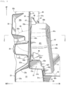
- FIG. 1 is a side view of the speaker disposition structure of the vehicle as viewed from the inside of a vehicle cabin
- FIG. 2 is a side view showing a state in which a speaker box has been removed from FIG. 1
- FIG. 3 is a side view of the speaker disposition structure of the vehicle as viewed from the inside and rear of the vehicle cabin.
- FIG. 4 is an arrow cross-sectional view taken along the A-A line in FIG. 1
- FIG. 5 is an arrow cross-sectional view of essential parts taken along the B-B line in FIG. 1
- FIG. 6 is an arrow cross-sectional view taken along the C-C line in FIG. 4 .
- a floor frame is omitted for convenience of illustration.
- a floor panel 10 that forms a floor surface of the vehicle cabin is mounted, and a bent piece 11 rising upward is integrally formed on a vehicle-width-direction end of the floor panel 10.
- a side sill 20 is joined and fixed to the bent piece 11 of the floor panel 10.
- the side sill 20 is a vehicle body strengthening member that has a side sill closed cross-section 23 extending in the vehicle front-rear direction by joining and fixing a side sill inner 21 and a side sill outer 22 together.
- the side sill inner 21 includes an upper joined flange 21a, an upper wall 21b extending inward in the vehicle width direction from the lower end of the joined flange 21a, an inner wall 21c extending downward from the vehicle-width-direction inner end of the upper wall 21b, a lower wall extending outward in the vehicle width direction from the lower end of the inner wall 21c, and a lower joined flange extending downward from the vehicle-width-direction outer end of the lower wall.
- the side sill outer 22 includes an upper joined flange 22a, an upper wall 22b extending outward in the vehicle width direction from the lower end of the joined flange 22a, an outer wall 22c extending downward from the vehicle-width-direction outer end of the upper wall 22b, a lower wall extending inward in the vehicle width direction from the lower end of the inner wall 22c, and a lower joined flange extending downward from the vehicle-width-direction inner end of the lower wall.
- the bent piece 11 of the floor panel 10 is joined and fixed to the inner wall 21c of the side sill inner 21.
- the upper joined flange 21a of the side sill inner 21 and the upper joined flange 22a of the side sill outer 22 are joined and fixed together.
- the lower joined flange of the side sill inner 21 and the lower joined flange of the side sill outer 22 are joined and fixed together.
- a floor frame 12 having a hat-shaped cross section is connected to the top face of the floor panel 10.
- the floor frame 12 has a floor frame front portion 13 and a floor frame rear portion 14, and extends in the vehicle front-rear direction, and the floor frame front portion 13 is attached across a lower portion of a later-described dash panel 37 and a front portion of the floor panel 10.
- a floor frame closed cross-section extending in the vehicle front-rear direction is formed between the floor frame rear portion 14 and the floor panel 10, thereby improving the lower vehicle body rigidity.
- a hinge pillar 30 that extends in the vehicle up-down direction between the side sill 20 extending in the vehicle front-rear direction at a vehicle lower portion and a front pillar 15 extending in a diagonal direction at a vehicle upper portion, and that connects the side sill 20 and the front pillar 15.
- the front pillar 15 extends diagonally upward and rearward from the front end to the rear end, and the front pillar 15 is a vehicle body strengthening member that has a front pillar closed cross-section extending in the longitudinal direction of the front pillar 15 by joining and fixing a front pillar inner and a front pillar outer together.
- the hinge pillar 30 is a vehicle body strengthening member that has a hinge pillar closed cross-section 33 extending in the vehicle up-down direction by joining and fixing a hinge pillar inner 31 and a hinge pillar outer 32 together, the upper end of the hinge pillar 30 is fixed to the diagonal lower end of the front pillar 15, and the lower end of the hinge pillar 30 is fixed to the side sill 20.
- the hinge pillar inner 31 has a front joined flange 31a, a front-side step portion 31b, an inner wall 31c, a rear-side step portion 31d, a rear joined flange 31e, and also includes a front extending portion 31f extending further forward from the front joined flange 31a.
- the hinge pillar outer 32 is produced by integrally forming a front joined flange 32a, a front wall 32b, an outer wall 32c, a rear wall 32d, and a rear joined flange 32e to have a hat-shaped cross section in plan view.
- the front wall 32b extends outward in the vehicle width direction from the rear end of the front joined flange 32a.
- the outer wall 32c extends from the vehicle-width-direction outer end of the front wall 32b toward the rear of the vehicle.
- the rear wall 32d extends inward in the vehicle width direction from the rear end of the outer wall 32c.
- the rear joined flange 32e extends from the vehicle-width-direction inner end of the rear wall 32d toward the rear of the vehicle.
- the front joined flange 31a of the hinge pillar inner 31 and the front joined flange 32a of the hinge pillar outer 32 are joined and fixed together, and the rear joined flange 31e of the hinge pillar inner 31 and the rear joined flange 32e of the hinge pillar outer 32 are joined and fixed together to form the hinge pillar 30.
- the second opening 35 is formed such that the outer-side box part 43 of the speaker box 40 can at least partially extend through the second opening 35.
- an opening 34 is formed at a middle portion in the up-down direction of the inner wall 31c of the hinge pillar inner 31, and an opening 35 for attaching an outer-side box part 43 of a later-described speaker box 40 is formed at a lower portion of the inner wall 31c below the opening 34.
- vehicle-exterior-side faces of the side sill 20, the front pillar 15 and the hinge pillar 30 are integrally covered with a cab side outer panel 16.
- a hinge reinforcement 36 is joined and fixed at a portion at which a body-side hinge bracket of a door hinge is attached.
- the side sill 20, the front pillar 15 and the hinge pillar 30 are formed on the right side and left side in a substantially symmetrical structure, and the dash panel 37 connecting front ends of a pair of left and right hinge pillars 30, 30 to each other in the vehicle width direction is mounted as shown in FIG. 1 and FIG. 2 .
- FIG. 17 in FIG. 1 and FIG. 2 represents an apron reinforcement
- 18 in FIG. 1 , FIG. 2 , FIG. 4 and FIG. 6 represents a connection reinforcement that diagonally connects the apron reinforcement 17 and the hinge pillar 30,
- 38 in FIG. 4 represents a gusset as a high-rigidity member that extends in the front-rear direction and connects a wheel arch for a front wheel and the hinge pillar 30.
- FIG. 7 is a perspective view showing an inner-side box part
- FIG. 8(a) is a perspective view of an outer-side box part as viewed from the front and the vehicle-width-direction outer side of the vehicle
- FIG. 8(b) is a perspective view of the outer-side box part as viewed from the front and the vehicle-width-direction inner side of the vehicle.
- a bass reflex type speaker box 40 is fixed to the hinge pillar 30 in the vicinity of the side sill 20.
- this speaker box 40 includes an inner-side box part 42 formed of a resin member that holds the speaker 41, and an outer-side box part 43 formed of a sheet metal, located on the vehicle-width direction outer side relative to the inner-side box part 42.
- the speaker 41 includes: a frame 41a having a damper, a cone, etc. therein; a yoke 41b located at a neck portion of the frame 41a; and a speaker grill 41c attached to the open side of the cone.
- a gap S1 in which a wire harness 39 as a vehicle component is to be placed is formed at a vehicle-interior-side upper part of the side sill 20, more specifically, above the upper wall 21b of the side sill inner 21.
- the outer-side box part 43 includes an upper-side flange 43a, a lower-side flange 43b, a front-side flange 43c, a rear-side flange 43d, and a bulge 43e bulging out from the respective flanges to the vicinity of the outer wall 32c of the hinge pillar outer 32.
- the bulge 43e is formed in a dorm shape, and a hollow portion S2 is formed inside the bulge 43e.
- the upper-side flange 43a, the front-side flange 43c and the rear-side flange 43d among the respective flanges 43a, 43b, 43c, 43d are fixed to a vehicle-width-direction inner-side face of the inner wall 31c of the hinge pillar inner 31, at the edge of the opening 35 shown in FIG. 2 , by joining means such as spot welding (see FIG. 5 and FIG. 6 ) .
- the lower-side flange 43b of the outer-side box part 43 is fixed to the side sill 20 that is a vehicle-body framework member. More specifically, the lower-side flange 43b is interposed and fixed between the upper joined flange 21a of the side sill inner 21 and the upper joined flange 22a of the side sill outer 22.
- the inner-side box part 42 includes a front face wall 42a, an upper wall 42b, a rear face wall 42c, an upper transverse wall 42d, an upper vertical wall 42e, a lower transverse wall 42f, a lower vertical wall 42g, a lower wall 42h, and a front wall 42i and a rear wall 42j shown in FIG. 6 .
- the front face wall 42a forms a front face on the vehicle-width-direction inner side of the speaker box 40.
- a cylindrical speaker support 42k extending toward the inside of a space portion inside the inner-side box part 42, that is, toward the vehicle-width-direction outer side, is integrally formed at an upper portion of the front face wall 42a, and the speaker 41 is supported by this support 42k.
- the upper wall 42b extends outward in the vehicle width direction from the upper end of the front face wall 42a.
- the rear face wall 42c extends downward from the vehicle-width-direction outer end of the upper wall 42b.
- the rear face wall 42c as a whole forms an abutting part 44 that abuts the hinge pillar inner 31 through the flanges 43a to 43d of the outer-side box part 43. Further, formed in the rear face wall 42c is a communication opening 45 that communicates the hollow portion S2 on the outer-side box part 43 side to an upper space forming portion S3 on the inner-side box part 42 side.
- the upper space forming portion S3 is a space portion that bulges inward in the vehicle width direction from the abutting part 44 above the gap S1, and holds the speaker 41 through the speaker support 42k.
- the gap S1 is surrounded by the upper joined flange 21a and the upper wall 21b of the side sill inner 21 and the upper transverse wall 42d and upper vertical wall 42e of the inner-side box part 42, and extending in the vehicle front-rear direction.
- the upper transverse wall 42d extends inward in the vehicle width direction from the lower end of the rear face wall 42c.
- the upper vertical wall 42e extends downward from the vehicle-width-direction inner end of the upper transverse wall 42d.
- the lower transverse wall 42f extends inward in the vehicle width direction from the lower end of the upper vertical wall 42e.
- the lower vertical wall 42g extends downward from the vehicle-width-direction inner end of the lower transverse wall 42f.
- the lower wall 42h extends inward in the vehicle width direction from the lower end of the lower vertical wall 42g, and connects the lower end of the lower vertical wall 42g to front face wall 42a.
- the front wall 42i closes the front of the inner-side box part 42 surrounded by the parts 42a to 42h.
- the rear wall 42j closes the rear of the inner-side box part 42 surrounded by the parts 42a to 42h.
- a port opening 46 is formed to open in a lower part of the front wall 42i of the inner-side box part 42.
- a pair of front and rear mounting seats 47, 47 are integrally formed at a top portion of the inner-side box part 42, and a flange 48 that protrudes rearward of the vehicle and extends in the up-down direction is integrally formed at a rear portion of the inner-side box part 42, on the upper side of the upper transverse wall 42d.
- the mounting seats 47 and the flange 48 are fastened and fixed to the hinge pillar inner 31 using fastening members 49 such as bolts and nuts.
- an extended space forming portion S4 that extends downward from the upper space forming portion S3 and is adjacent to the vehicle-width-direction inner side of the gap S1 is formed.
- This extended space forming portion S4 is a space portion surrounded by the upper vertical wall 42e, the lower transverse wall 42f, the lower vertical wall 42g, the lower wall 42h, and the lower portions of the front face wall 42a, the front wall 42i and the rear wall 42j corresponding to these parts 42e to 42h.
- the upper space forming portion (S3) and the extended space forming portion (S4) are arranged next to one another in an up-down direction and together confine a closed space S5.
- the extended space forming portion S4 is formed such that the vehicle-width-direction dimension in a cross section orthogonal to the vehicle front-rear direction (namely, a vehicle-width-direction cross section) is smaller in the lower portion than in the upper portion.
- the extended space forming portion S4 is formed such that, in the cross section orthogonal to the vehicle front-rear direction, the vehicle-width-direction dimension becomes smaller toward the bottom.
- the vehicle-width-direction dimension may become smaller stepwise or may become smaller continuously, and this embodiment adopts a structure in which the vehicle-width-direction dimension becomes smaller stepwise as shown in FIG. 5 .
- the extended space forming portion S4 is provided so as to secure the capacity of the speaker box 40 without cramping the cabin (driver room), and to secure a layout of the wire harness 39 as a vehicle component by the gap S1. Further, by forming the extended space forming portion S4 such the vehicle-width-direction dimension is smaller in the lower portion than in the upper portion, an increase in air flow resistance in the speaker box 40 during reproducing sound from the speaker 41 is prevented so as to reproduce expected bass.
- the extended space forming portion S4 has an inner wall 42m located on the vehicle-width-direction inner side (see the lower portion of the front face wall 42a corresponding to the region of the extended space forming portion S4), and an outer wall located on the vehicle-width-direction outer side (see each part of the upper vertical wall 42e, the lower transverse wall 42f, and the lower vertical wall 42g).
- the inner wall 42m is arranged to be inclined inward of the vehicle cabin (that is, inward in the vehicle width direction), towards the bottom.
- this configuration secures the capacity of the speaker box 40 as the inner wall 42m is inclined inward of the vehicle cabin, towards the bottom.
- a step-down portion (the lower transverse wall 42f) that is stepped down toward the inside of the vehicle cabin is provided at the lower portion of the gap S1.
- a first gap G1 in the vehicle width direction is formed between the lower vertical wall 42g of the inner-side box part 42 and the inner wall 21c of the side sill inner 21 and the bent piece 11 of the floor panel 10.
- a second gap G2 in the up-down direction is formed between the lower wall 42h of the inner-side box part 42 and the floor panel 10.
- the first gap G1 and the second gap G2 are formed so as to prevent occurrence of abnormal noise due to vibration when the vehicle is traveling.
- an arrow F indicates the direction toward the front of the vehicle
- an arrow R indicates the direction toward the rear of the vehicle
- an arrow IN indicates the direction toward the inner side in the vehicle width direction
- an arrow OUT indicates the direction toward the outer side in the vehicle width direction
- an arrow UP indicates the direction toward the upper side of the vehicle.
- the speaker disposition structure of the vehicle of the embodiment includes: the hinge pillar 30 extending in the vehicle up-down direction; the side sill 20 fixed to the lower end of the hinge pillar 30 and extending in the vehicle front-rear direction; the speaker box 40 that holds the speaker 41 and is fixed to the hinge pillar 30 in the vicinity of the side sill 20; and the gap S1 for arranging the vehicle component (see the wire harness 39) at the upper part of the vehicle-interior side of the side sill 20, wherein the speaker box 40 includes: the abutting part 44 abutting the hinge pillar 30; the upper space forming portion S3 that bulges inward in the vehicle width direction from the abutting part 44 above the gap S1 and that holds the speaker 41; and the extended space forming portion S4 that extends downward from the upper space forming portion S3 and is adjacent to the vehicle-width-direction inner side of the gap S1, wherein the upper space forming portion S3 and the extended space forming portion S4 are arranged next to one another in an up
- the extended space forming portion S4 is provided so as to secure the capacity of the speaker box 40 without cramping the cabin, and to secure a layout of the vehicle component (wire harness 39) by the gap S1.
- the vehicle-width-direction dimension of the extended space forming portion S4 is smaller in the lower portion than in the upper portion, it is possible to prevent an increase in air flow resistance in the speaker box 40 during reproducing sound from the speaker 41, and to reproduce expected bass.
- the extended space forming portion S4 has the inner wall 42m located on the vehicle-width-direction inner side, and the outer wall located on the vehicle-width-direction outer side (see the upper vertical wall 42e, the lower transverse wall 42f, and the lower vertical wall 42g), and the inner wall 42m is arranged to be inclined inward of the vehicle cabin, toward the bottom (see FIG. 5 ).
- the inner wall 42m is inclined inward of the vehicle cabin toward the bottom while securing a layout of the vehicle component (wire harness 39) by the extended space forming portion S4 adjacent to the vehicle-width-direction inner side of the gap S1, it is possible to secure the capacity of the speaker box 40 by the inclination toward the inside of the vehicle cabin.
- the extended space forming portion S4 has the inner wall 42m located on the vehicle-width-direction inner side and the outer wall located on the vehicle-width-direction outer side (the upper vertical wall 42e, the lower transverse wall 42f, and the lower vertical wall 42g), and the outer wall has a step-down portion (see the lower transverse wall 42f) that is stepped down toward the inside of the vehicle cabin, at the lower portion of the gap S1 (see FIG. 5 ).
- the extended space forming portion S4 can be provided while avoiding interference with the vehicle component (the wire harness 39) arranged in the gap S1 and the side sill 20 located immediately below the gap S1, and the capacity of the speaker box 40 can be secured by the extended space forming portion S4.
- the vehicle component of the present invention corresponds to the wire harness 39 of the embodiment
- the outer wall of the extended space forming portion S4 corresponds to the upper vertical wall 42e, the lower transverse wall 42f and the lower vertical wall 42g, and the step-down portion corresponds to the lower transverse wall 42f
- the present invention is not necessarily limited to only the configuration of the embodiment.
- the vehicle-width-direction dimension in the cross section orthogonal to the vehicle front-rear direction is smaller in the lower portion than in the upper portion
- the embodiment adopts a structure in which the vehicle-width-direction dimension becomes smaller stepwise
- the vehicle-width-direction dimension may become smaller continuously.
- the present invention is useful for a speaker disposition structure of a vehicle, including: a hinge pillar extending in the vehicle up-down direction; a side sill fixed to a lower end of the hinge pillar and extending in the vehicle front-rear direction; a speaker box that holds a speaker and is fixed to the hinge pillar in the vicinity of the side sill; and a gap for arranging a vehicle component at an upper part of the vehicle-interior side of the side sill.
Landscapes
- Engineering & Computer Science (AREA)
- Mechanical Engineering (AREA)
- Chemical & Material Sciences (AREA)
- Combustion & Propulsion (AREA)
- Transportation (AREA)
- Fittings On The Vehicle Exterior For Carrying Loads, And Devices For Holding Or Mounting Articles (AREA)
- Body Structure For Vehicles (AREA)
- Details Of Audible-Bandwidth Transducers (AREA)
Description
- The present invention relates to a speaker disposition structure of a vehicle, more specifically to a speaker disposition structure of a vehicle, including: a hinge pillar extending in the vehicle up-down direction; a side sill fixed to a lower end of the hinge pillar and extending in the vehicle front-rear direction; a speaker box that holds a speaker and is fixed to the hinge pillar in the vicinity of the side sill; and a gap for arranging a vehicle component at an upper part of the vehicle-interior side of the side sill.
- In general, when a sufficient capacity of a speaker box is secured, sufficient air compression and expansion can be obtained inside the speaker box, and expected sound can be output to the inside of a vehicle cabin.
- Therefore, for the speaker box fixed to a hinge pillar, expansion of the speaker box inward of the vehicle cabin is required for the purpose of securing the capacity of the speaker box and improving the bass reproduction efficiency.
- If the speaker box is expanded inward in the vehicle width direction, the space in the vehicle cabin becomes narrower, and thus it is difficult to expand the speaker box inward in the vehicle width direction.
- Hence, it is considered to expand the speaker box downward from the upper space forming portion, and to locate the speaker box adjacent, in the vehicle width direction, to a gap, above a side sill, for arranging a vehicle component (see a wire harness) therein.
- In this case, if the space inside the speaker box in a section adjacent to the gap is excessively narrowed, resistance that impedes the flow of air in the speaker box becomes larger, causing a problem of disabling reproduction of expected bass during sound reproduction from the speaker.
-
JP 2018-167709 A WO 2013/084324 A1 discloses a structure in which a wire harness as a vehicle component is arranged at an upper part of the vehicle-interior side of a side sill. - However, neither of
JP 2018-167709 A WO 2013/084324 A1 discloses a configuration suggesting the technical idea of the present invention. -
EP 3 587 189 A1 - Therefore, an object of the present invention is to provide a speaker disposition structure of a vehicle that can secure a capacity of a speaker box without cramping a cabin, establish a layout of a vehicle component at a lower part of the vehicle-interior side of a hinge pillar, and improve the bass reproduction efficiency by a decrease in air flow resistance in the speaker box.
- A speaker disposition structure of a vehicle according to
claim 1. - The vehicle component may be a wire harness.
- According to the configuration, by providing the extended space forming portion, the capacity of the speaker box can be secured without cramping the cabin, and a layout of the vehicle component can be secured by the gap.
- Further, since the vehicle-width-direction dimension of the extended space forming portion is smaller in the lower portion than in the upper portion, that is, the vehicle-width-direction dimension of the extended space forming portion is larger in the upper portion than in the lower portion, it is possible to prevent an increase in air flow resistance in the speaker box during sound reproduction from the speaker, and to reproduce expected bass.
- In one embodiment of the present invention, the extended space forming portion has an inner wall located on the inner side in the vehicle width direction, and an outer wall located on the outer side in the vehicle width direction, and the inner wall is arranged to be inclined inward of the vehicle cabin, toward the bottom.
- According to this configuration, since the inner wall is inclined inward of the vehicle cabin toward the bottom while securing a layout of the vehicle component by the extended space forming portion adjacent to the vehicle-width-direction inner side of the gap, it is possible to secure the capacity of the speaker box by the inclination toward the inside of the vehicle cabin.
- In one embodiment of the present invention, the extended space forming portion has the inner wall located on the inner side in the vehicle width direction and the outer wall located on the outer side in the vehicle width direction, and the outer wall has a step-down portion that is stepped down toward the inside of the vehicle cabin, at the lower portion of the gap.
- According to this configuration, the extended space forming portion can be provided while avoiding interference with the vehicle component arranged in the gap and the side sill located immediately below the gap, and the capacity of the speaker box can be secured by the extended space forming portion.
- In one embodiment of the present invention, the upper space forming portion has an upper wall extending outward in the vehicle width direction from an upper end of a front face wall of the upper space forming portion, wherein the upper space forming portion has a rear face wall extending downward from a vehicle-width-direction outer end of the upper wall.
- In one embodiment of the present invention, the rear face wall forms an abutting part that abuts a hinge pillar inner through at least one flange of an outer-side box part of the speaker box.
- In one embodiment of the present invention, a communication opening is formed in the rear face wall that communicates a hollow portion on the outer-side box part side to the upper space forming portion on the inner-side box part side.
- In one embodiment of the present invention, the extended space forming portion comprises an upper vertical wall, a lower transverse wall, a lower vertical wall, these walls forming an outer wall located on an outer side in the vehicle width direction, a lower wall, and lower portions of a front face wall, a front wall and a rear wall corresponding to respective parts of the speaker box.
- In one embodiment of the present invention, the gap is at least partially surrounded by at least one out of an upper joined flange and an upper wall of a side sill inner of the side sill and at least partially surrounded by an upper transverse wall and an upper vertical wall of an inner-side box part of the speaker box, wherein the gap extends in the vehicle front-rear direction.
- In one embodiment of the present invention, a hinge pillar outer has a hat-shaped cross section in plan view.
- In one embodiment of the present invention, the hinge pillar outer is integrally formed by a front joined flange, a front wall, an outer wall, a rear wall, and a rear joined flange to have a hat-shaped cross section in plan view.
- According to the present invention, a first opening is formed at an inner wall of an hinge pillar inner, preferably at a middle portion in the up-down direction of the hinge pillar inner, and a second opening for attaching an outer-side box part of the speaker box is formed at a lower portion of the inner wall below the first opening.
- In one embodiment of the present invention, the second opening is formed such that the outer-side box part of the speaker box can at least partially extend through the second opening.
- In one embodiment of the present invention, the vehicle-width-direction dimension of the extended space forming portion becomes smaller stepwise and/or becomes smaller continuously toward the bottom.
- In one embodiment of the present invention, a first gap is formed in the vehicle width direction between a lower vertical wall of an inner-side box part of the speaker box and the inner wall of a side sill inner.
- In one embodiment of the present invention, a second gap is formed in an up-down direction between a lower wall of the inner-side box part of the speaker box and a floor panel.
- According to the present invention, there are advantageous effects, such as making it possible to secure the capacity of the speaker box without cramping the cabin, establish a layout of the vehicle component at a lower part of the vehicle-interior side of the hinge pillar, and improve the bass reproduction efficiency by a decrease in air flow resistance in the speaker box.
-
-
FIG. 1 is a side view of a speaker disposition structure of a vehicle of the present invention as viewed from the inside of a vehicle cabin. -
FIG. 2 is a side view showing a state in which a speaker box has been removed fromFIG. 1 . -
FIG. 3 is a perspective view of the speaker disposition structure of the vehicle as viewed from the inside and rear of the vehicle cabin. -
FIG. 4 is an arrow cross-sectional view taken along the A-A line inFIG. 1 . -
FIG. 5 is an arrow cross-sectional view of essential parts taken along the B-B line inFIG. 1 . -
FIG. 6 is an arrow cross-sectional view taken along the C-C line inFIG. 4 . -
FIG. 7 is a perspective view showing an inner-side box part of the speaker box. -
FIG. 8(a) is a perspective view of an outer-side box part as viewed from the front and outside of the vehicle, andFIG. 8(b) is a perspective view of the outer-side box part as viewed from the front and inside of the vehicle. - The object of securing the capacity of the speaker box without cramping the cabin, establishing a layout of the vehicle component at a lower part of the vehicle-interior side of the hinge pillar, and improving the bass reproduction efficiency by a decrease in air flow resistance in the speaker box is realized by a speaker disposition structure of a vehicle, including: a hinge pillar extending in the vehicle up-down direction; a side sill fixed to a lower end of the hinge pillar and extending in a vehicle front-rear direction; a speaker box that holds a speaker, and is fixed to the hinge pillar in the vicinity of the side sill; and a gap for arranging a vehicle component at an upper part of the vehicle-interior side of the side sill, wherein the speaker box includes: an abutting part abutting the hinge pillar; an upper space forming portion that bulges inward in the vehicle width direction from the abutting part above the gap and that holds the speaker; and an extended space forming portion that extends downward from the upper space forming portion and is adjacent to the vehicle-width-direction inner side of the gap, wherein the upper space forming portion and the extended space forming portion are arranged next to one another in an up-down direction and together confine a closed space, and the extended space forming portion is formed such that a vehicle-width-direction dimension in a cross section orthogonal to the vehicle front-rear direction is smaller in a lower portion than in an upper portion.
- One embodiment of the present invention will be described in detail below based on the drawings.
- The drawings show a speaker disposition structure of a vehicle, wherein
FIG. 1 is a side view of the speaker disposition structure of the vehicle as viewed from the inside of a vehicle cabin,FIG. 2 is a side view showing a state in which a speaker box has been removed fromFIG. 1 , andFIG. 3 is a side view of the speaker disposition structure of the vehicle as viewed from the inside and rear of the vehicle cabin. -
FIG. 4 is an arrow cross-sectional view taken along the A-A line inFIG. 1 ,FIG. 5 is an arrow cross-sectional view of essential parts taken along the B-B line inFIG. 1 , andFIG. 6 is an arrow cross-sectional view taken along the C-C line inFIG. 4 . InFIG. 1 andFIG. 2 , a floor frame is omitted for convenience of illustration. - First, a front vehicle-body structure of the vehicle will be described before describing the speaker disposition structure.
- As shown in
FIG. 4 andFIG. 5 , afloor panel 10 that forms a floor surface of the vehicle cabin is mounted, and abent piece 11 rising upward is integrally formed on a vehicle-width-direction end of thefloor panel 10. - A
side sill 20 is joined and fixed to thebent piece 11 of thefloor panel 10. - The
side sill 20 is a vehicle body strengthening member that has a side sill closedcross-section 23 extending in the vehicle front-rear direction by joining and fixing a side sill inner 21 and a side sill outer 22 together. - As shown in
FIG. 4 andFIG. 5 , the side sill inner 21 includes an upper joinedflange 21a, anupper wall 21b extending inward in the vehicle width direction from the lower end of the joinedflange 21a, aninner wall 21c extending downward from the vehicle-width-direction inner end of theupper wall 21b, a lower wall extending outward in the vehicle width direction from the lower end of theinner wall 21c, and a lower joined flange extending downward from the vehicle-width-direction outer end of the lower wall. - As shown in
FIG. 4 andFIG. 5 , the side sill outer 22 includes an upper joinedflange 22a, anupper wall 22b extending outward in the vehicle width direction from the lower end of the joinedflange 22a, anouter wall 22c extending downward from the vehicle-width-direction outer end of theupper wall 22b, a lower wall extending inward in the vehicle width direction from the lower end of theinner wall 22c, and a lower joined flange extending downward from the vehicle-width-direction inner end of the lower wall. - The
bent piece 11 of thefloor panel 10 is joined and fixed to theinner wall 21c of the side sill inner 21. - Moreover, the upper joined
flange 21a of the side sill inner 21 and the upper joinedflange 22a of the side sill outer 22 are joined and fixed together. Similarly, the lower joined flange of the side sill inner 21 and the lower joined flange of the side sill outer 22 are joined and fixed together. - As shown in
FIG. 3 , afloor frame 12 having a hat-shaped cross section is connected to the top face of thefloor panel 10. Thefloor frame 12 has a floorframe front portion 13 and a floor framerear portion 14, and extends in the vehicle front-rear direction, and the floorframe front portion 13 is attached across a lower portion of a later-describeddash panel 37 and a front portion of thefloor panel 10. - A floor frame closed cross-section extending in the vehicle front-rear direction is formed between the floor frame
rear portion 14 and thefloor panel 10, thereby improving the lower vehicle body rigidity. - As shown in
FIG. 1 andFIG. 2 , provided is ahinge pillar 30 that extends in the vehicle up-down direction between theside sill 20 extending in the vehicle front-rear direction at a vehicle lower portion and afront pillar 15 extending in a diagonal direction at a vehicle upper portion, and that connects theside sill 20 and thefront pillar 15. - Here, the
front pillar 15 extends diagonally upward and rearward from the front end to the rear end, and thefront pillar 15 is a vehicle body strengthening member that has a front pillar closed cross-section extending in the longitudinal direction of thefront pillar 15 by joining and fixing a front pillar inner and a front pillar outer together. - As shown in
FIG. 1 to FIG. 6 , thehinge pillar 30 is a vehicle body strengthening member that has a hinge pillar closedcross-section 33 extending in the vehicle up-down direction by joining and fixing a hinge pillar inner 31 and a hinge pillar outer 32 together, the upper end of thehinge pillar 30 is fixed to the diagonal lower end of thefront pillar 15, and the lower end of thehinge pillar 30 is fixed to theside sill 20. - As shown in
FIG. 2 andFIG. 6 , the hinge pillar inner 31 has a front joinedflange 31a, a front-side step portion 31b, aninner wall 31c, a rear-side step portion 31d, a rear joinedflange 31e, and also includes a front extendingportion 31f extending further forward from the front joinedflange 31a. - As shown in
FIG. 6 , the hinge pillar outer 32 is produced by integrally forming a front joinedflange 32a, afront wall 32b, anouter wall 32c, arear wall 32d, and a rear joinedflange 32e to have a hat-shaped cross section in plan view. - The
front wall 32b extends outward in the vehicle width direction from the rear end of the front joinedflange 32a. Theouter wall 32c extends from the vehicle-width-direction outer end of thefront wall 32b toward the rear of the vehicle. Therear wall 32d extends inward in the vehicle width direction from the rear end of theouter wall 32c. Further, the rear joinedflange 32e extends from the vehicle-width-direction inner end of therear wall 32d toward the rear of the vehicle. - Furthermore, as shown in
FIG. 6 , the front joinedflange 31a of the hinge pillar inner 31 and the front joinedflange 32a of the hinge pillar outer 32 are joined and fixed together, and the rear joinedflange 31e of the hinge pillar inner 31 and the rear joinedflange 32e of the hinge pillar outer 32 are joined and fixed together to form thehinge pillar 30. Furthermore, as shown inFIG. 6 , thesecond opening 35 is formed such that the outer-side box part 43 of thespeaker box 40 can at least partially extend through thesecond opening 35. - As shown in
FIG. 2 , anopening 34 is formed at a middle portion in the up-down direction of theinner wall 31c of the hinge pillar inner 31, and anopening 35 for attaching an outer-side box part 43 of a later-describedspeaker box 40 is formed at a lower portion of theinner wall 31c below theopening 34. - As shown in
FIG. 3 ,FIG. 5 andFIG. 6 , vehicle-exterior-side faces of theside sill 20, thefront pillar 15 and thehinge pillar 30 are integrally covered with a cab sideouter panel 16. - As shown in
FIG. 6 , on the hinge pillar outer 32 of thehinge pillar 30, ahinge reinforcement 36 is joined and fixed at a portion at which a body-side hinge bracket of a door hinge is attached. - Although only the structure on the right side of the vehicle is shown in the drawings, the
side sill 20, thefront pillar 15 and thehinge pillar 30 are formed on the right side and left side in a substantially symmetrical structure, and thedash panel 37 connecting front ends of a pair of left andright hinge pillars FIG. 1 andFIG. 2 . - 17 in
FIG. 1 andFIG. 2 represents an apron reinforcement, 18 inFIG. 1 ,FIG. 2 ,FIG. 4 andFIG. 6 represents a connection reinforcement that diagonally connects theapron reinforcement 17 and thehinge pillar FIG. 4 represents a gusset as a high-rigidity member that extends in the front-rear direction and connects a wheel arch for a front wheel and thehinge pillar 30. - Next, the speaker disposition structure of the vehicle will be described in detail.
-
FIG. 7 is a perspective view showing an inner-side box part,FIG. 8(a) is a perspective view of an outer-side box part as viewed from the front and the vehicle-width-direction outer side of the vehicle, andFIG. 8(b) is a perspective view of the outer-side box part as viewed from the front and the vehicle-width-direction inner side of the vehicle. - As shown in
FIG. 1 andFIG. 3 , a bass reflextype speaker box 40 is fixed to thehinge pillar 30 in the vicinity of theside sill 20. - As shown in
FIG. 5 andFIG. 6 , thisspeaker box 40 includes an inner-side box part 42 formed of a resin member that holds thespeaker 41, and an outer-side box part 43 formed of a sheet metal, located on the vehicle-width direction outer side relative to the inner-side box part 42. - As shown in
FIG. 5 andFIG. 6 , thespeaker 41 includes: aframe 41a having a damper, a cone, etc. therein; ayoke 41b located at a neck portion of theframe 41a; and aspeaker grill 41c attached to the open side of the cone. - Meanwhile, as shown in
FIG. 5 , a gap S1 in which awire harness 39 as a vehicle component is to be placed is formed at a vehicle-interior-side upper part of theside sill 20, more specifically, above theupper wall 21b of the side sill inner 21. - As shown in
FIG. 5 ,FIG. 6 andFIG. 8 , the outer-side box part 43 includes an upper-side flange 43a, a lower-side flange 43b, a front-side flange 43c, a rear-side flange 43d, and abulge 43e bulging out from the respective flanges to the vicinity of theouter wall 32c of the hinge pillar outer 32. - The
bulge 43e is formed in a dorm shape, and a hollow portion S2 is formed inside thebulge 43e. - The upper-
side flange 43a, the front-side flange 43c and the rear-side flange 43d among therespective flanges inner wall 31c of the hinge pillar inner 31, at the edge of theopening 35 shown inFIG. 2 , by joining means such as spot welding (seeFIG. 5 andFIG. 6 ) . - As shown in
FIG. 5 , the lower-side flange 43b of the outer-side box part 43 is fixed to theside sill 20 that is a vehicle-body framework member. More specifically, the lower-side flange 43b is interposed and fixed between the upper joinedflange 21a of the side sill inner 21 and the upper joinedflange 22a of the side sill outer 22. - As shown in
FIG. 1 ,FIG. 3 to FIG. 7 , particularly inFIG. 5 , the inner-side box part 42 includes afront face wall 42a, anupper wall 42b, arear face wall 42c, an uppertransverse wall 42d, an uppervertical wall 42e, a lowertransverse wall 42f, a lowervertical wall 42g, alower wall 42h, and afront wall 42i and arear wall 42j shown inFIG. 6 . - As shown in
FIG. 5 , thefront face wall 42a forms a front face on the vehicle-width-direction inner side of thespeaker box 40. Acylindrical speaker support 42k extending toward the inside of a space portion inside the inner-side box part 42, that is, toward the vehicle-width-direction outer side, is integrally formed at an upper portion of thefront face wall 42a, and thespeaker 41 is supported by thissupport 42k. - The
upper wall 42b extends outward in the vehicle width direction from the upper end of thefront face wall 42a. Therear face wall 42c extends downward from the vehicle-width-direction outer end of theupper wall 42b. - The
rear face wall 42c as a whole forms anabutting part 44 that abuts the hinge pillar inner 31 through theflanges 43a to 43d of the outer-side box part 43. Further, formed in therear face wall 42c is acommunication opening 45 that communicates the hollow portion S2 on the outer-side box part 43 side to an upper space forming portion S3 on the inner-side box part 42 side. - Here, the upper space forming portion S3 is a space portion that bulges inward in the vehicle width direction from the abutting
part 44 above the gap S1, and holds thespeaker 41 through thespeaker support 42k. - The gap S1 is surrounded by the upper joined
flange 21a and theupper wall 21b of the side sill inner 21 and the uppertransverse wall 42d and uppervertical wall 42e of the inner-side box part 42, and extending in the vehicle front-rear direction. - As shown in
FIG. 5 , the uppertransverse wall 42d extends inward in the vehicle width direction from the lower end of therear face wall 42c. Moreover, the uppervertical wall 42e extends downward from the vehicle-width-direction inner end of the uppertransverse wall 42d. Further, the lowertransverse wall 42f extends inward in the vehicle width direction from the lower end of the uppervertical wall 42e. Furthermore, the lowervertical wall 42g extends downward from the vehicle-width-direction inner end of the lowertransverse wall 42f. Additionally, thelower wall 42h extends inward in the vehicle width direction from the lower end of the lowervertical wall 42g, and connects the lower end of the lowervertical wall 42g tofront face wall 42a. - As shown in
FIG. 6 andFIG. 7 , thefront wall 42i closes the front of the inner-side box part 42 surrounded by theparts 42a to 42h. As shown inFIG. 3 andFIG. 6 , therear wall 42j closes the rear of the inner-side box part 42 surrounded by theparts 42a to 42h. - As shown in
FIG. 4 andFIG. 7 , since thespeaker box 40 of this embodiment is a bass reflex type enclosure, aport opening 46 is formed to open in a lower part of thefront wall 42i of the inner-side box part 42. - As shown in
FIG. 3 , a pair of front and rear mountingseats side box part 42, and aflange 48 that protrudes rearward of the vehicle and extends in the up-down direction is integrally formed at a rear portion of the inner-side box part 42, on the upper side of the uppertransverse wall 42d. Moreover, the mountingseats 47 and theflange 48 are fastened and fixed to the hinge pillar inner 31 usingfastening members 49 such as bolts and nuts. - As shown in
FIG. 5 , on the lower side of the inner-side box part 42 relative to the uppertransverse wall 42d, an extended space forming portion S4 that extends downward from the upper space forming portion S3 and is adjacent to the vehicle-width-direction inner side of the gap S1 is formed. - This extended space forming portion S4 is a space portion surrounded by the upper
vertical wall 42e, the lowertransverse wall 42f, the lowervertical wall 42g, thelower wall 42h, and the lower portions of thefront face wall 42a, thefront wall 42i and therear wall 42j corresponding to theseparts 42e to 42h. - As shown in
FIG. 5 , the upper space forming portion (S3) and the extended space forming portion (S4) are arranged next to one another in an up-down direction and together confine a closed space S5. - Moreover, as shown in
FIG. 5 , the extended space forming portion S4 is formed such that the vehicle-width-direction dimension in a cross section orthogonal to the vehicle front-rear direction (namely, a vehicle-width-direction cross section) is smaller in the lower portion than in the upper portion. In other words, the extended space forming portion S4 is formed such that, in the cross section orthogonal to the vehicle front-rear direction, the vehicle-width-direction dimension becomes smaller toward the bottom. - For the structure in which the vehicle-width-direction dimension is smaller in the lower portion than in the upper portion, the vehicle-width-direction dimension may become smaller stepwise or may become smaller continuously, and this embodiment adopts a structure in which the vehicle-width-direction dimension becomes smaller stepwise as shown in
FIG. 5 . - The extended space forming portion S4 is provided so as to secure the capacity of the
speaker box 40 without cramping the cabin (driver room), and to secure a layout of thewire harness 39 as a vehicle component by the gap S1. Further, by forming the extended space forming portion S4 such the vehicle-width-direction dimension is smaller in the lower portion than in the upper portion, an increase in air flow resistance in thespeaker box 40 during reproducing sound from thespeaker 41 is prevented so as to reproduce expected bass. - As shown in
FIG. 5 , the extended space forming portion S4 has aninner wall 42m located on the vehicle-width-direction inner side (see the lower portion of thefront face wall 42a corresponding to the region of the extended space forming portion S4), and an outer wall located on the vehicle-width-direction outer side (see each part of the uppervertical wall 42e, the lowertransverse wall 42f, and the lowervertical wall 42g). - As shown in
FIG. 5 , theinner wall 42m is arranged to be inclined inward of the vehicle cabin (that is, inward in the vehicle width direction), towards the bottom. Thus, this configuration secures the capacity of thespeaker box 40 as theinner wall 42m is inclined inward of the vehicle cabin, towards the bottom. - Furthermore, as shown in
FIG. 5 , in the outer wall (the uppervertical wall 42e, the lowertransverse wall 42f, the lowervertical wall 42g) of the extended space forming portion S4, a step-down portion (the lowertransverse wall 42f) that is stepped down toward the inside of the vehicle cabin is provided at the lower portion of the gap S1. Thus, this configuration provides the extended space forming portion S4 while avoiding interference with the side sill 20 (more specifically, the side sill inner 21) located immediately below the gap S1, and secures the capacity of thespeaker box 40 by the extended space forming portion S4. - As shown in
FIG. 5 , a first gap G1 in the vehicle width direction is formed between the lowervertical wall 42g of the inner-side box part 42 and theinner wall 21c of the side sill inner 21 and thebent piece 11 of thefloor panel 10. - Furthermore, as shown in
FIG. 5 , a second gap G2 in the up-down direction is formed between thelower wall 42h of the inner-side box part 42 and thefloor panel 10. - The first gap G1 and the second gap G2 are formed so as to prevent occurrence of abnormal noise due to vibration when the vehicle is traveling.
- In the drawings, an arrow F indicates the direction toward the front of the vehicle, an arrow R indicates the direction toward the rear of the vehicle, an arrow IN indicates the direction toward the inner side in the vehicle width direction, an arrow OUT indicates the direction toward the outer side in the vehicle width direction, and an arrow UP indicates the direction toward the upper side of the vehicle.
- Thus, the speaker disposition structure of the vehicle of the embodiment includes: the hinge pillar 30 extending in the vehicle up-down direction; the side sill 20 fixed to the lower end of the hinge pillar 30 and extending in the vehicle front-rear direction; the speaker box 40 that holds the speaker 41 and is fixed to the hinge pillar 30 in the vicinity of the side sill 20; and the gap S1 for arranging the vehicle component (see the wire harness 39) at the upper part of the vehicle-interior side of the side sill 20, wherein the speaker box 40 includes: the abutting part 44 abutting the hinge pillar 30; the upper space forming portion S3 that bulges inward in the vehicle width direction from the abutting part 44 above the gap S1 and that holds the speaker 41; and the extended space forming portion S4 that extends downward from the upper space forming portion S3 and is adjacent to the vehicle-width-direction inner side of the gap S1, wherein the upper space forming portion S3 and the extended space forming portion S4 are arranged next to one another in an up-down direction and together confine the closed space S5, and the extended space forming portion S4 is formed such that the vehicle-width-direction dimension in a cross section orthogonal to the vehicle front-rear direction is smaller in the lower portion than in the upper portion (see
FIG. 1 andFIG. 5 ). - According to this configuration, the extended space forming portion S4 is provided so as to secure the capacity of the
speaker box 40 without cramping the cabin, and to secure a layout of the vehicle component (wire harness 39) by the gap S1. - Moreover, since the vehicle-width-direction dimension of the extended space forming portion S4 is smaller in the lower portion than in the upper portion, it is possible to prevent an increase in air flow resistance in the
speaker box 40 during reproducing sound from thespeaker 41, and to reproduce expected bass. - Further, in one embodiment of the present invention, the extended space forming portion S4 has the
inner wall 42m located on the vehicle-width-direction inner side, and the outer wall located on the vehicle-width-direction outer side (see the uppervertical wall 42e, the lowertransverse wall 42f, and the lowervertical wall 42g), and theinner wall 42m is arranged to be inclined inward of the vehicle cabin, toward the bottom (seeFIG. 5 ). - According to this configuration, since the
inner wall 42m is inclined inward of the vehicle cabin toward the bottom while securing a layout of the vehicle component (wire harness 39) by the extended space forming portion S4 adjacent to the vehicle-width-direction inner side of the gap S1, it is possible to secure the capacity of thespeaker box 40 by the inclination toward the inside of the vehicle cabin. - Furthermore, in one embodiment of the present invention, the extended space forming portion S4 has the
inner wall 42m located on the vehicle-width-direction inner side and the outer wall located on the vehicle-width-direction outer side (the uppervertical wall 42e, the lowertransverse wall 42f, and the lowervertical wall 42g), and the outer wall has a step-down portion (see the lowertransverse wall 42f) that is stepped down toward the inside of the vehicle cabin, at the lower portion of the gap S1 (seeFIG. 5 ). - Thus, according to this configuration, the extended space forming portion S4 can be provided while avoiding interference with the vehicle component (the wire harness 39) arranged in the gap S1 and the
side sill 20 located immediately below the gap S1, and the capacity of thespeaker box 40 can be secured by the extended space forming portion S4. - For correspondence between the configuration of the present invention and the embodiment, the vehicle component of the present invention corresponds to the
wire harness 39 of the embodiment, and similarly the outer wall of the extended space forming portion S4 corresponds to the uppervertical wall 42e, the lowertransverse wall 42f and the lowervertical wall 42g, and the step-down portion corresponds to the lowertransverse wall 42f, but the present invention is not necessarily limited to only the configuration of the embodiment. - For example, as the structure of the extended space forming portion S4 in which the vehicle-width-direction dimension in the cross section orthogonal to the vehicle front-rear direction is smaller in the lower portion than in the upper portion, although the embodiment adopts a structure in which the vehicle-width-direction dimension becomes smaller stepwise, the vehicle-width-direction dimension may become smaller continuously.
- As described above, the present invention is useful for a speaker disposition structure of a vehicle, including: a hinge pillar extending in the vehicle up-down direction; a side sill fixed to a lower end of the hinge pillar and extending in the vehicle front-rear direction; a speaker box that holds a speaker and is fixed to the hinge pillar in the vicinity of the side sill; and a gap for arranging a vehicle component at an upper part of the vehicle-interior side of the side sill.
-
- 20
- Side sill
- 30
- Hinge pillar
- 39
- Wire harness (vehicle component)
- 40
- Speaker box
- 41
- Speaker
- 42e
- Upper vertical wall (outer wall)
- 42f
- Lower transverse wall (outer wall, step-down portion)
- 42g
- Lower vertical wall (outer wall)
- 42m
- Inner wall
- 44
- Abutting part
- S1
- Gap
- S3
- Upper space forming portion
- S4
- Extended space forming portion
- S5
- Closed space
Claims (9)
- A speaker disposition structure of a vehicle, the speaker disposition structure comprising:a hinge pillar (30) extending in a vehicle up-down direction;a side sill (20) fixed to a lower end of the hinge pillar (30) and extending in a vehicle front-rear direction;a speaker box (40) that holds a speaker (41) and is fixed to the hinge pillar (30) in a vicinity of the side sill (20); anda gap (S1) for arranging a vehicle component (39) at an upper part of a vehicle-interior side of the side sill (20),the speaker box (40) includes:an outer-box part (43);an abutting part (44) abutting the hinge pillar (30);an upper space forming portion (S3) that bulges inward in a vehicle width direction from the abutting part (44) above the gap (S1) and that holds the speaker (41); andan extended space forming portion (S4) that extends downward from the upper space forming portion (S3) and is adjacent to a vehicle-width-direction inner side of the gap (S1),wherein the upper space forming portion (S3) and the extended space forming portion (S4) are arranged next to one another in an up-down direction and together confine a closed space (S5), andthe extended space forming portion (S4) is formed such that a vehicle-width-direction dimension in a cross section orthogonal to the vehicle front-rear direction is smaller in a lower portion of the extended space forming portion (S4) than in an upper space forming portion (S3) of the extended space forming portion (S4),a first opening (34) is formed at an inner wall (31c) of an hinge pillar inner (31), preferably at a middle portion in the up-down direction of the hinge pillar inner (31), anda second opening (35) for attaching the outer-side box part (43) of the speaker box (40) is formed at a lower portion of the inner wall (31c) below the first opening (34) .
- The speaker disposition structure of a vehicle according to claim 1,wherein the extended space forming portion (S4) has an inner wall (42m) located on an inner side in the vehicle width direction, and an outer wall (42e, 42f, 42g) located on an outer side in the vehicle width direction, andthe inner wall (42m) is arranged to be inclined inward of a vehicle cabin, toward a bottom.
- The speaker disposition structure of a vehicle according to claim 1 or 2,wherein the extended space forming portion (S4) has an inner wall (42m) located on an inner side in the vehicle width direction, and an outer wall (42e, 42f, 42g) located on an outer side in the vehicle width direction, andthe outer wall (42e, 42f, 42g) has a step-down portion (42f) that is stepped down toward an inside of a vehicle cabin, at a lower portion of the gap (S1).
- The speaker disposition structure of a vehicle according to any of claims 1 to 3,wherein the upper space forming portion (S3) has an upper wall (42b) extending outward in the vehicle width direction from an upper end of a front face wall (42a) of the upper space forming portion (S3), wherein the upper space forming portion (S3) has a rear face wall (42c) extending downward from a vehicle-width-direction outer end of the upper wall (42b),wherein the rear face wall (42c) forms an abutting part (44) that abuts a hinge pillar inner (31) through at least one flange (43a to 43d) of an outer-side box part (43) of the speaker box (40), and/ora communication opening (45) is formed in the rear face wall (42c) that communicates a hollow portion (S2) on the outer-side box part (43) side to the upper space forming portion (S3) on the inner-side box part (42) side.
- The speaker disposition structure of a vehicle according to any of claims 1 to 4,
wherein the extended space forming portion (S4) comprises an upper vertical wall (42e), a lower transverse wall (42f), a lower vertical wall (42g), these walls (42e, 42f, 42g) forming an outer wall (42e, 42f, 42g) located on an outer side in the vehicle width direction, a lower wall (42h), and lower portions of a front face wall (42a), a front wall (42i) and a rear wall (42j) corresponding to respective parts of the speaker box (40). - The speaker disposition structure of a vehicle according to any of claims 1 to 5,
wherein the gap (S1) is at least partially surrounded by at least one out of an upper joined flange (21a) and an upper wall (21b) of a side sill inner (21) of the side sill (20) and at least partially surrounded by an upper transverse wall (42d) and an upper vertical wall (42e) of an inner-side box part (42) of the speaker box (40), wherein the gap (S1) extends in the vehicle front-rear direction. - The speaker disposition structure of a vehicle according to any of claims 1 to 6,wherein a hinge pillar outer (32) has a hat-shaped cross section in plan view, and/orwherein the hinge pillar outer (32) is integrally formed by a front joined flange (32a), a front wall (32b), an outer wall (32c), a rear wall (32d), and a rear joined flange (32e) to have a hat-shaped cross section in plan view.
- The speaker disposition structure of a vehicle according to any of claims 1 to 7,
wherein the vehicle-width-direction dimension of the extended space forming portion (S4) becomes smaller stepwise and/or becomes smaller continuously toward the bottom. - The speaker disposition structure of a vehicle according to any of claims 1 to 8,wherein a first gap (G1) is formed in the vehicle width direction between a lower vertical wall (42g) of an inner-side box part (42) of the speaker box (40) and the inner wall (21c) of a side sill inner (21), and/orwherein a second gap (G2) is formed in an up-down direction between a lower wall (42h) of the inner-side box part (42) of the speaker box (40) and a floor panel (10).
Applications Claiming Priority (1)
| Application Number | Priority Date | Filing Date | Title |
|---|---|---|---|
| JP2020158369A JP7413961B2 (en) | 2020-09-23 | 2020-09-23 | Vehicle speaker arrangement structure |
Publications (2)
| Publication Number | Publication Date |
|---|---|
| EP3974258A1 EP3974258A1 (en) | 2022-03-30 |
| EP3974258B1 true EP3974258B1 (en) | 2024-03-13 |
Family
ID=77710643
Family Applications (1)
| Application Number | Title | Priority Date | Filing Date |
|---|---|---|---|
| EP21195973.9A Active EP3974258B1 (en) | 2020-09-23 | 2021-09-10 | Speaker disposition structure of vehicle |
Country Status (4)
| Country | Link |
|---|---|
| US (1) | US11535171B2 (en) |
| EP (1) | EP3974258B1 (en) |
| JP (1) | JP7413961B2 (en) |
| CN (1) | CN114248697B (en) |
Families Citing this family (1)
| Publication number | Priority date | Publication date | Assignee | Title |
|---|---|---|---|---|
| FR3137653B1 (en) * | 2022-07-05 | 2024-07-05 | Renault Sas | Front structure of electric motor vehicle equipped with a sound generator |
Family Cites Families (5)
| Publication number | Priority date | Publication date | Assignee | Title |
|---|---|---|---|---|
| JPS61132443A (en) * | 1984-12-01 | 1986-06-19 | Nissan Motor Co Ltd | Loudspeaker mounting structure for vehicle |
| JP4661515B2 (en) * | 2005-10-14 | 2011-03-30 | 三菱自動車工業株式会社 | Vehicle door structure |
| US9290208B2 (en) | 2011-12-07 | 2016-03-22 | Toyota Jidosha Kabushiki Kaisha | Vehicle body lower portion structure |
| JP6468308B2 (en) * | 2017-03-30 | 2019-02-13 | マツダ株式会社 | Vehicle speaker arrangement structure |
| JP6544377B2 (en) * | 2017-03-30 | 2019-07-17 | マツダ株式会社 | Speaker arrangement structure of vehicle |
-
2020
- 2020-09-23 JP JP2020158369A patent/JP7413961B2/en active Active
-
2021
- 2021-08-27 CN CN202110995152.XA patent/CN114248697B/en active Active
- 2021-09-10 EP EP21195973.9A patent/EP3974258B1/en active Active
- 2021-09-23 US US17/482,451 patent/US11535171B2/en active Active
Also Published As
| Publication number | Publication date |
|---|---|
| EP3974258A1 (en) | 2022-03-30 |
| JP2022052159A (en) | 2022-04-04 |
| US20220089099A1 (en) | 2022-03-24 |
| CN114248697B (en) | 2023-11-03 |
| US11535171B2 (en) | 2022-12-27 |
| CN114248697A (en) | 2022-03-29 |
| JP7413961B2 (en) | 2024-01-16 |
Similar Documents
| Publication | Publication Date | Title |
|---|---|---|
| US9248865B2 (en) | Vehicle body front structure | |
| JP5982843B2 (en) | Lower body structure of the vehicle | |
| EP3974259B1 (en) | Speaker disposition structure of vehicle | |
| US7040639B2 (en) | Vehicle body structure employing gussets fastened to cross member portion between damper bases | |
| JP2019217812A (en) | Lower part vehicle body structure | |
| JP5515760B2 (en) | Rear body structure of the vehicle | |
| JP2019217813A (en) | Lower part vehicle body structure | |
| JP2019217814A (en) | Lower vehicular body structure | |
| EP3808636B1 (en) | Front vehicle-body structure of vehicle and vehicle | |
| JP2009248805A (en) | Vehicle front body structure of automobile | |
| JP4822191B2 (en) | Body front structure | |
| EP3974258B1 (en) | Speaker disposition structure of vehicle | |
| EP3632778B1 (en) | Front vehicle-body structure and vehicle | |
| JP6652848B2 (en) | Body front structure | |
| JP6128324B2 (en) | Lower body structure of the vehicle | |
| JP2006111162A (en) | Vehicle front structure | |
| US20220073144A1 (en) | Vehicle | |
| JP7456339B2 (en) | Vehicle front body structure | |
| JP7413963B2 (en) | Vehicle speaker arrangement structure | |
| JP2022097815A (en) | Structure of vehicular battery pack | |
| JP6061906B2 (en) | Car body rear structure | |
| US11420682B2 (en) | Vehicle-body structure of vehicle | |
| JP2002104248A (en) | Seat support part reinforcement structure in automobile body | |
| CN118850196A (en) | Front enclosure sound cavity structure and vehicle having the same | |
| JP2008296846A (en) | Reinforcement structure of vehicle cross section |
Legal Events
| Date | Code | Title | Description |
|---|---|---|---|
| PUAI | Public reference made under article 153(3) epc to a published international application that has entered the european phase |
Free format text: ORIGINAL CODE: 0009012 |
|
| STAA | Information on the status of an ep patent application or granted ep patent |
Free format text: STATUS: THE APPLICATION HAS BEEN PUBLISHED |
|
| AK | Designated contracting states |
Kind code of ref document: A1 Designated state(s): AL AT BE BG CH CY CZ DE DK EE ES FI FR GB GR HR HU IE IS IT LI LT LU LV MC MK MT NL NO PL PT RO RS SE SI SK SM TR |
|
| STAA | Information on the status of an ep patent application or granted ep patent |
Free format text: STATUS: REQUEST FOR EXAMINATION WAS MADE |
|
| 17P | Request for examination filed |
Effective date: 20220804 |
|
| RBV | Designated contracting states (corrected) |
Designated state(s): AL AT BE BG CH CY CZ DE DK EE ES FI FR GB GR HR HU IE IS IT LI LT LU LV MC MK MT NL NO PL PT RO RS SE SI SK SM TR |
|
| GRAP | Despatch of communication of intention to grant a patent |
Free format text: ORIGINAL CODE: EPIDOSNIGR1 |
|
| STAA | Information on the status of an ep patent application or granted ep patent |
Free format text: STATUS: GRANT OF PATENT IS INTENDED |
|
| INTG | Intention to grant announced |
Effective date: 20231214 |
|
| GRAS | Grant fee paid |
Free format text: ORIGINAL CODE: EPIDOSNIGR3 |
|
| GRAA | (expected) grant |
Free format text: ORIGINAL CODE: 0009210 |
|
| STAA | Information on the status of an ep patent application or granted ep patent |
Free format text: STATUS: THE PATENT HAS BEEN GRANTED |
|
| AK | Designated contracting states |
Kind code of ref document: B1 Designated state(s): AL AT BE BG CH CY CZ DE DK EE ES FI FR GB GR HR HU IE IS IT LI LT LU LV MC MK MT NL NO PL PT RO RS SE SI SK SM TR |
|
| REG | Reference to a national code |
Ref country code: GB Ref legal event code: FG4D |
|
| REG | Reference to a national code |
Ref country code: CH Ref legal event code: EP |
|
| REG | Reference to a national code |
Ref country code: DE Ref legal event code: R096 Ref document number: 602021010324 Country of ref document: DE |
|
| REG | Reference to a national code |
Ref country code: IE Ref legal event code: FG4D |
|
| PG25 | Lapsed in a contracting state [announced via postgrant information from national office to epo] |
Ref country code: LT Free format text: LAPSE BECAUSE OF FAILURE TO SUBMIT A TRANSLATION OF THE DESCRIPTION OR TO PAY THE FEE WITHIN THE PRESCRIBED TIME-LIMIT Effective date: 20240313 |
|
| REG | Reference to a national code |
Ref country code: LT Ref legal event code: MG9D |
|
| PG25 | Lapsed in a contracting state [announced via postgrant information from national office to epo] |
Ref country code: GR Free format text: LAPSE BECAUSE OF FAILURE TO SUBMIT A TRANSLATION OF THE DESCRIPTION OR TO PAY THE FEE WITHIN THE PRESCRIBED TIME-LIMIT Effective date: 20240614 |
|
| REG | Reference to a national code |
Ref country code: NL Ref legal event code: MP Effective date: 20240313 |
|
| PG25 | Lapsed in a contracting state [announced via postgrant information from national office to epo] |
Ref country code: HR Free format text: LAPSE BECAUSE OF FAILURE TO SUBMIT A TRANSLATION OF THE DESCRIPTION OR TO PAY THE FEE WITHIN THE PRESCRIBED TIME-LIMIT Effective date: 20240313 Ref country code: RS Free format text: LAPSE BECAUSE OF FAILURE TO SUBMIT A TRANSLATION OF THE DESCRIPTION OR TO PAY THE FEE WITHIN THE PRESCRIBED TIME-LIMIT Effective date: 20240613 |
|
| PG25 | Lapsed in a contracting state [announced via postgrant information from national office to epo] |
Ref country code: ES Free format text: LAPSE BECAUSE OF FAILURE TO SUBMIT A TRANSLATION OF THE DESCRIPTION OR TO PAY THE FEE WITHIN THE PRESCRIBED TIME-LIMIT Effective date: 20240313 |
|
| PG25 | Lapsed in a contracting state [announced via postgrant information from national office to epo] |
Ref country code: RS Free format text: LAPSE BECAUSE OF FAILURE TO SUBMIT A TRANSLATION OF THE DESCRIPTION OR TO PAY THE FEE WITHIN THE PRESCRIBED TIME-LIMIT Effective date: 20240613 Ref country code: NO Free format text: LAPSE BECAUSE OF FAILURE TO SUBMIT A TRANSLATION OF THE DESCRIPTION OR TO PAY THE FEE WITHIN THE PRESCRIBED TIME-LIMIT Effective date: 20240613 Ref country code: LT Free format text: LAPSE BECAUSE OF FAILURE TO SUBMIT A TRANSLATION OF THE DESCRIPTION OR TO PAY THE FEE WITHIN THE PRESCRIBED TIME-LIMIT Effective date: 20240313 Ref country code: HR Free format text: LAPSE BECAUSE OF FAILURE TO SUBMIT A TRANSLATION OF THE DESCRIPTION OR TO PAY THE FEE WITHIN THE PRESCRIBED TIME-LIMIT Effective date: 20240313 Ref country code: GR Free format text: LAPSE BECAUSE OF FAILURE TO SUBMIT A TRANSLATION OF THE DESCRIPTION OR TO PAY THE FEE WITHIN THE PRESCRIBED TIME-LIMIT Effective date: 20240614 Ref country code: FI Free format text: LAPSE BECAUSE OF FAILURE TO SUBMIT A TRANSLATION OF THE DESCRIPTION OR TO PAY THE FEE WITHIN THE PRESCRIBED TIME-LIMIT Effective date: 20240313 Ref country code: ES Free format text: LAPSE BECAUSE OF FAILURE TO SUBMIT A TRANSLATION OF THE DESCRIPTION OR TO PAY THE FEE WITHIN THE PRESCRIBED TIME-LIMIT Effective date: 20240313 Ref country code: BG Free format text: LAPSE BECAUSE OF FAILURE TO SUBMIT A TRANSLATION OF THE DESCRIPTION OR TO PAY THE FEE WITHIN THE PRESCRIBED TIME-LIMIT Effective date: 20240313 |
|
| REG | Reference to a national code |
Ref country code: AT Ref legal event code: MK05 Ref document number: 1665473 Country of ref document: AT Kind code of ref document: T Effective date: 20240313 |
|
| PG25 | Lapsed in a contracting state [announced via postgrant information from national office to epo] |
Ref country code: SE Free format text: LAPSE BECAUSE OF FAILURE TO SUBMIT A TRANSLATION OF THE DESCRIPTION OR TO PAY THE FEE WITHIN THE PRESCRIBED TIME-LIMIT Effective date: 20240313 Ref country code: LV Free format text: LAPSE BECAUSE OF FAILURE TO SUBMIT A TRANSLATION OF THE DESCRIPTION OR TO PAY THE FEE WITHIN THE PRESCRIBED TIME-LIMIT Effective date: 20240313 |
|
| PG25 | Lapsed in a contracting state [announced via postgrant information from national office to epo] |
Ref country code: NL Free format text: LAPSE BECAUSE OF FAILURE TO SUBMIT A TRANSLATION OF THE DESCRIPTION OR TO PAY THE FEE WITHIN THE PRESCRIBED TIME-LIMIT Effective date: 20240313 |
|
| PG25 | Lapsed in a contracting state [announced via postgrant information from national office to epo] |
Ref country code: NL Free format text: LAPSE BECAUSE OF FAILURE TO SUBMIT A TRANSLATION OF THE DESCRIPTION OR TO PAY THE FEE WITHIN THE PRESCRIBED TIME-LIMIT Effective date: 20240313 |
|
| PG25 | Lapsed in a contracting state [announced via postgrant information from national office to epo] |
Ref country code: IS Free format text: LAPSE BECAUSE OF FAILURE TO SUBMIT A TRANSLATION OF THE DESCRIPTION OR TO PAY THE FEE WITHIN THE PRESCRIBED TIME-LIMIT Effective date: 20240713 |
|
| PG25 | Lapsed in a contracting state [announced via postgrant information from national office to epo] |
Ref country code: PT Free format text: LAPSE BECAUSE OF FAILURE TO SUBMIT A TRANSLATION OF THE DESCRIPTION OR TO PAY THE FEE WITHIN THE PRESCRIBED TIME-LIMIT Effective date: 20240715 Ref country code: SM Free format text: LAPSE BECAUSE OF FAILURE TO SUBMIT A TRANSLATION OF THE DESCRIPTION OR TO PAY THE FEE WITHIN THE PRESCRIBED TIME-LIMIT Effective date: 20240313 |
|
| PG25 | Lapsed in a contracting state [announced via postgrant information from national office to epo] |
Ref country code: CZ Free format text: LAPSE BECAUSE OF FAILURE TO SUBMIT A TRANSLATION OF THE DESCRIPTION OR TO PAY THE FEE WITHIN THE PRESCRIBED TIME-LIMIT Effective date: 20240313 Ref country code: EE Free format text: LAPSE BECAUSE OF FAILURE TO SUBMIT A TRANSLATION OF THE DESCRIPTION OR TO PAY THE FEE WITHIN THE PRESCRIBED TIME-LIMIT Effective date: 20240313 |
|
| PG25 | Lapsed in a contracting state [announced via postgrant information from national office to epo] |
Ref country code: AT Free format text: LAPSE BECAUSE OF FAILURE TO SUBMIT A TRANSLATION OF THE DESCRIPTION OR TO PAY THE FEE WITHIN THE PRESCRIBED TIME-LIMIT Effective date: 20240313 |
|
| PG25 | Lapsed in a contracting state [announced via postgrant information from national office to epo] |
Ref country code: PL Free format text: LAPSE BECAUSE OF FAILURE TO SUBMIT A TRANSLATION OF THE DESCRIPTION OR TO PAY THE FEE WITHIN THE PRESCRIBED TIME-LIMIT Effective date: 20240313 |
|
| PG25 | Lapsed in a contracting state [announced via postgrant information from national office to epo] |
Ref country code: SK Free format text: LAPSE BECAUSE OF FAILURE TO SUBMIT A TRANSLATION OF THE DESCRIPTION OR TO PAY THE FEE WITHIN THE PRESCRIBED TIME-LIMIT Effective date: 20240313 |
|
| PG25 | Lapsed in a contracting state [announced via postgrant information from national office to epo] |
Ref country code: SM Free format text: LAPSE BECAUSE OF FAILURE TO SUBMIT A TRANSLATION OF THE DESCRIPTION OR TO PAY THE FEE WITHIN THE PRESCRIBED TIME-LIMIT Effective date: 20240313 Ref country code: SK Free format text: LAPSE BECAUSE OF FAILURE TO SUBMIT A TRANSLATION OF THE DESCRIPTION OR TO PAY THE FEE WITHIN THE PRESCRIBED TIME-LIMIT Effective date: 20240313 Ref country code: RO Free format text: LAPSE BECAUSE OF FAILURE TO SUBMIT A TRANSLATION OF THE DESCRIPTION OR TO PAY THE FEE WITHIN THE PRESCRIBED TIME-LIMIT Effective date: 20240313 Ref country code: PT Free format text: LAPSE BECAUSE OF FAILURE TO SUBMIT A TRANSLATION OF THE DESCRIPTION OR TO PAY THE FEE WITHIN THE PRESCRIBED TIME-LIMIT Effective date: 20240715 Ref country code: PL Free format text: LAPSE BECAUSE OF FAILURE TO SUBMIT A TRANSLATION OF THE DESCRIPTION OR TO PAY THE FEE WITHIN THE PRESCRIBED TIME-LIMIT Effective date: 20240313 Ref country code: IS Free format text: LAPSE BECAUSE OF FAILURE TO SUBMIT A TRANSLATION OF THE DESCRIPTION OR TO PAY THE FEE WITHIN THE PRESCRIBED TIME-LIMIT Effective date: 20240713 Ref country code: EE Free format text: LAPSE BECAUSE OF FAILURE TO SUBMIT A TRANSLATION OF THE DESCRIPTION OR TO PAY THE FEE WITHIN THE PRESCRIBED TIME-LIMIT Effective date: 20240313 Ref country code: CZ Free format text: LAPSE BECAUSE OF FAILURE TO SUBMIT A TRANSLATION OF THE DESCRIPTION OR TO PAY THE FEE WITHIN THE PRESCRIBED TIME-LIMIT Effective date: 20240313 Ref country code: AT Free format text: LAPSE BECAUSE OF FAILURE TO SUBMIT A TRANSLATION OF THE DESCRIPTION OR TO PAY THE FEE WITHIN THE PRESCRIBED TIME-LIMIT Effective date: 20240313 |
|
| PG25 | Lapsed in a contracting state [announced via postgrant information from national office to epo] |
Ref country code: IT Free format text: LAPSE BECAUSE OF FAILURE TO SUBMIT A TRANSLATION OF THE DESCRIPTION OR TO PAY THE FEE WITHIN THE PRESCRIBED TIME-LIMIT Effective date: 20240313 |
|
| REG | Reference to a national code |
Ref country code: DE Ref legal event code: R097 Ref document number: 602021010324 Country of ref document: DE |
|
| PG25 | Lapsed in a contracting state [announced via postgrant information from national office to epo] |
Ref country code: IT Free format text: LAPSE BECAUSE OF FAILURE TO SUBMIT A TRANSLATION OF THE DESCRIPTION OR TO PAY THE FEE WITHIN THE PRESCRIBED TIME-LIMIT Effective date: 20240313 |
|
| PG25 | Lapsed in a contracting state [announced via postgrant information from national office to epo] |
Ref country code: DK Free format text: LAPSE BECAUSE OF FAILURE TO SUBMIT A TRANSLATION OF THE DESCRIPTION OR TO PAY THE FEE WITHIN THE PRESCRIBED TIME-LIMIT Effective date: 20240313 |
|
| PLBE | No opposition filed within time limit |
Free format text: ORIGINAL CODE: 0009261 |
|
| STAA | Information on the status of an ep patent application or granted ep patent |
Free format text: STATUS: NO OPPOSITION FILED WITHIN TIME LIMIT |
|
| PG25 | Lapsed in a contracting state [announced via postgrant information from national office to epo] |
Ref country code: DK Free format text: LAPSE BECAUSE OF FAILURE TO SUBMIT A TRANSLATION OF THE DESCRIPTION OR TO PAY THE FEE WITHIN THE PRESCRIBED TIME-LIMIT Effective date: 20240313 |
|
| 26N | No opposition filed |
Effective date: 20241216 |
|
| PG25 | Lapsed in a contracting state [announced via postgrant information from national office to epo] |
Ref country code: SI Free format text: LAPSE BECAUSE OF FAILURE TO SUBMIT A TRANSLATION OF THE DESCRIPTION OR TO PAY THE FEE WITHIN THE PRESCRIBED TIME-LIMIT Effective date: 20240313 Ref country code: MC Free format text: LAPSE BECAUSE OF FAILURE TO SUBMIT A TRANSLATION OF THE DESCRIPTION OR TO PAY THE FEE WITHIN THE PRESCRIBED TIME-LIMIT Effective date: 20240313 |
|
| REG | Reference to a national code |
Ref country code: CH Ref legal event code: PL |
|
| PG25 | Lapsed in a contracting state [announced via postgrant information from national office to epo] |
Ref country code: LU Free format text: LAPSE BECAUSE OF NON-PAYMENT OF DUE FEES Effective date: 20240910 |
|
| REG | Reference to a national code |
Ref country code: BE Ref legal event code: MM Effective date: 20240930 |
|
| PG25 | Lapsed in a contracting state [announced via postgrant information from national office to epo] |
Ref country code: BE Free format text: LAPSE BECAUSE OF NON-PAYMENT OF DUE FEES Effective date: 20240930 |
|
| PG25 | Lapsed in a contracting state [announced via postgrant information from national office to epo] |
Ref country code: FR Free format text: LAPSE BECAUSE OF NON-PAYMENT OF DUE FEES Effective date: 20240930 |
|
| PG25 | Lapsed in a contracting state [announced via postgrant information from national office to epo] |
Ref country code: CH Free format text: LAPSE BECAUSE OF NON-PAYMENT OF DUE FEES Effective date: 20240930 |
|
| PG25 | Lapsed in a contracting state [announced via postgrant information from national office to epo] |
Ref country code: IE Free format text: LAPSE BECAUSE OF NON-PAYMENT OF DUE FEES Effective date: 20240910 |
|
| PGFP | Annual fee paid to national office [announced via postgrant information from national office to epo] |
Ref country code: DE Payment date: 20250730 Year of fee payment: 5 |
|
| PG25 | Lapsed in a contracting state [announced via postgrant information from national office to epo] |
Ref country code: CY Free format text: LAPSE BECAUSE OF FAILURE TO SUBMIT A TRANSLATION OF THE DESCRIPTION OR TO PAY THE FEE WITHIN THE PRESCRIBED TIME-LIMIT; INVALID AB INITIO Effective date: 20210910 |
|
| PG25 | Lapsed in a contracting state [announced via postgrant information from national office to epo] |
Ref country code: HU Free format text: LAPSE BECAUSE OF FAILURE TO SUBMIT A TRANSLATION OF THE DESCRIPTION OR TO PAY THE FEE WITHIN THE PRESCRIBED TIME-LIMIT; INVALID AB INITIO Effective date: 20210910 |