EP3974224A1 - Automatic transmission control device - Google Patents
Automatic transmission control device Download PDFInfo
- Publication number
- EP3974224A1 EP3974224A1 EP21194406.1A EP21194406A EP3974224A1 EP 3974224 A1 EP3974224 A1 EP 3974224A1 EP 21194406 A EP21194406 A EP 21194406A EP 3974224 A1 EP3974224 A1 EP 3974224A1
- Authority
- EP
- European Patent Office
- Prior art keywords
- torque
- clutch
- speed
- motor
- output
- Prior art date
- Legal status (The legal status is an assumption and is not a legal conclusion. Google has not performed a legal analysis and makes no representation as to the accuracy of the status listed.)
- Granted
Links
Images


Classifications
-
- B—PERFORMING OPERATIONS; TRANSPORTING
- B60—VEHICLES IN GENERAL
- B60K—ARRANGEMENT OR MOUNTING OF PROPULSION UNITS OR OF TRANSMISSIONS IN VEHICLES; ARRANGEMENT OR MOUNTING OF PLURAL DIVERSE PRIME-MOVERS IN VEHICLES; AUXILIARY DRIVES FOR VEHICLES; INSTRUMENTATION OR DASHBOARDS FOR VEHICLES; ARRANGEMENTS IN CONNECTION WITH COOLING, AIR INTAKE, GAS EXHAUST OR FUEL SUPPLY OF PROPULSION UNITS IN VEHICLES
- B60K6/00—Arrangement or mounting of plural diverse prime-movers for mutual or common propulsion, e.g. hybrid propulsion systems comprising electric motors and internal combustion engines
- B60K6/20—Arrangement or mounting of plural diverse prime-movers for mutual or common propulsion, e.g. hybrid propulsion systems comprising electric motors and internal combustion engines the prime-movers consisting of electric motors and internal combustion engines, e.g. HEVs
- B60K6/22—Arrangement or mounting of plural diverse prime-movers for mutual or common propulsion, e.g. hybrid propulsion systems comprising electric motors and internal combustion engines the prime-movers consisting of electric motors and internal combustion engines, e.g. HEVs characterised by apparatus, components or means specially adapted for HEVs
- B60K6/38—Arrangement or mounting of plural diverse prime-movers for mutual or common propulsion, e.g. hybrid propulsion systems comprising electric motors and internal combustion engines the prime-movers consisting of electric motors and internal combustion engines, e.g. HEVs characterised by apparatus, components or means specially adapted for HEVs characterised by the driveline clutches
- B60K6/387—Actuated clutches, i.e. clutches engaged or disengaged by electric, hydraulic or mechanical actuating means
-
- B—PERFORMING OPERATIONS; TRANSPORTING
- B60—VEHICLES IN GENERAL
- B60K—ARRANGEMENT OR MOUNTING OF PROPULSION UNITS OR OF TRANSMISSIONS IN VEHICLES; ARRANGEMENT OR MOUNTING OF PLURAL DIVERSE PRIME-MOVERS IN VEHICLES; AUXILIARY DRIVES FOR VEHICLES; INSTRUMENTATION OR DASHBOARDS FOR VEHICLES; ARRANGEMENTS IN CONNECTION WITH COOLING, AIR INTAKE, GAS EXHAUST OR FUEL SUPPLY OF PROPULSION UNITS IN VEHICLES
- B60K6/00—Arrangement or mounting of plural diverse prime-movers for mutual or common propulsion, e.g. hybrid propulsion systems comprising electric motors and internal combustion engines
- B60K6/20—Arrangement or mounting of plural diverse prime-movers for mutual or common propulsion, e.g. hybrid propulsion systems comprising electric motors and internal combustion engines the prime-movers consisting of electric motors and internal combustion engines, e.g. HEVs
- B60K6/42—Arrangement or mounting of plural diverse prime-movers for mutual or common propulsion, e.g. hybrid propulsion systems comprising electric motors and internal combustion engines the prime-movers consisting of electric motors and internal combustion engines, e.g. HEVs characterised by the architecture of the hybrid electric vehicle
- B60K6/48—Parallel type
-
- B—PERFORMING OPERATIONS; TRANSPORTING
- B60—VEHICLES IN GENERAL
- B60K—ARRANGEMENT OR MOUNTING OF PROPULSION UNITS OR OF TRANSMISSIONS IN VEHICLES; ARRANGEMENT OR MOUNTING OF PLURAL DIVERSE PRIME-MOVERS IN VEHICLES; AUXILIARY DRIVES FOR VEHICLES; INSTRUMENTATION OR DASHBOARDS FOR VEHICLES; ARRANGEMENTS IN CONNECTION WITH COOLING, AIR INTAKE, GAS EXHAUST OR FUEL SUPPLY OF PROPULSION UNITS IN VEHICLES
- B60K6/00—Arrangement or mounting of plural diverse prime-movers for mutual or common propulsion, e.g. hybrid propulsion systems comprising electric motors and internal combustion engines
- B60K6/20—Arrangement or mounting of plural diverse prime-movers for mutual or common propulsion, e.g. hybrid propulsion systems comprising electric motors and internal combustion engines the prime-movers consisting of electric motors and internal combustion engines, e.g. HEVs
- B60K6/50—Architecture of the driveline characterised by arrangement or kind of transmission units
- B60K6/54—Transmission for changing ratio
- B60K6/547—Transmission for changing ratio the transmission being a stepped gearing
-
- B—PERFORMING OPERATIONS; TRANSPORTING
- B60—VEHICLES IN GENERAL
- B60W—CONJOINT CONTROL OF VEHICLE SUB-UNITS OF DIFFERENT TYPE OR DIFFERENT FUNCTION; CONTROL SYSTEMS SPECIALLY ADAPTED FOR HYBRID VEHICLES; ROAD VEHICLE DRIVE CONTROL SYSTEMS FOR PURPOSES NOT RELATED TO THE CONTROL OF A PARTICULAR SUB-UNIT
- B60W10/00—Conjoint control of vehicle sub-units of different type or different function
- B60W10/02—Conjoint control of vehicle sub-units of different type or different function including control of driveline clutches
-
- B—PERFORMING OPERATIONS; TRANSPORTING
- B60—VEHICLES IN GENERAL
- B60W—CONJOINT CONTROL OF VEHICLE SUB-UNITS OF DIFFERENT TYPE OR DIFFERENT FUNCTION; CONTROL SYSTEMS SPECIALLY ADAPTED FOR HYBRID VEHICLES; ROAD VEHICLE DRIVE CONTROL SYSTEMS FOR PURPOSES NOT RELATED TO THE CONTROL OF A PARTICULAR SUB-UNIT
- B60W10/00—Conjoint control of vehicle sub-units of different type or different function
- B60W10/04—Conjoint control of vehicle sub-units of different type or different function including control of propulsion units
- B60W10/06—Conjoint control of vehicle sub-units of different type or different function including control of propulsion units including control of combustion engines
-
- B—PERFORMING OPERATIONS; TRANSPORTING
- B60—VEHICLES IN GENERAL
- B60W—CONJOINT CONTROL OF VEHICLE SUB-UNITS OF DIFFERENT TYPE OR DIFFERENT FUNCTION; CONTROL SYSTEMS SPECIALLY ADAPTED FOR HYBRID VEHICLES; ROAD VEHICLE DRIVE CONTROL SYSTEMS FOR PURPOSES NOT RELATED TO THE CONTROL OF A PARTICULAR SUB-UNIT
- B60W10/00—Conjoint control of vehicle sub-units of different type or different function
- B60W10/04—Conjoint control of vehicle sub-units of different type or different function including control of propulsion units
- B60W10/08—Conjoint control of vehicle sub-units of different type or different function including control of propulsion units including control of electric propulsion units, e.g. motors or generators
-
- B—PERFORMING OPERATIONS; TRANSPORTING
- B60—VEHICLES IN GENERAL
- B60W—CONJOINT CONTROL OF VEHICLE SUB-UNITS OF DIFFERENT TYPE OR DIFFERENT FUNCTION; CONTROL SYSTEMS SPECIALLY ADAPTED FOR HYBRID VEHICLES; ROAD VEHICLE DRIVE CONTROL SYSTEMS FOR PURPOSES NOT RELATED TO THE CONTROL OF A PARTICULAR SUB-UNIT
- B60W10/00—Conjoint control of vehicle sub-units of different type or different function
- B60W10/10—Conjoint control of vehicle sub-units of different type or different function including control of change-speed gearings
- B60W10/11—Stepped gearings
-
- B—PERFORMING OPERATIONS; TRANSPORTING
- B60—VEHICLES IN GENERAL
- B60W—CONJOINT CONTROL OF VEHICLE SUB-UNITS OF DIFFERENT TYPE OR DIFFERENT FUNCTION; CONTROL SYSTEMS SPECIALLY ADAPTED FOR HYBRID VEHICLES; ROAD VEHICLE DRIVE CONTROL SYSTEMS FOR PURPOSES NOT RELATED TO THE CONTROL OF A PARTICULAR SUB-UNIT
- B60W20/00—Control systems specially adapted for hybrid vehicles
- B60W20/10—Controlling the power contribution of each of the prime movers to meet required power demand
- B60W20/11—Controlling the power contribution of each of the prime movers to meet required power demand using model predictive control [MPC] strategies, i.e. control methods based on models predicting performance
-
- B—PERFORMING OPERATIONS; TRANSPORTING
- B60—VEHICLES IN GENERAL
- B60W—CONJOINT CONTROL OF VEHICLE SUB-UNITS OF DIFFERENT TYPE OR DIFFERENT FUNCTION; CONTROL SYSTEMS SPECIALLY ADAPTED FOR HYBRID VEHICLES; ROAD VEHICLE DRIVE CONTROL SYSTEMS FOR PURPOSES NOT RELATED TO THE CONTROL OF A PARTICULAR SUB-UNIT
- B60W20/00—Control systems specially adapted for hybrid vehicles
- B60W20/10—Controlling the power contribution of each of the prime movers to meet required power demand
- B60W20/13—Controlling the power contribution of each of the prime movers to meet required power demand in order to stay within battery power input or output limits; in order to prevent overcharging or battery depletion
- B60W20/14—Controlling the power contribution of each of the prime movers to meet required power demand in order to stay within battery power input or output limits; in order to prevent overcharging or battery depletion in conjunction with braking regeneration
-
- B—PERFORMING OPERATIONS; TRANSPORTING
- B60—VEHICLES IN GENERAL
- B60W—CONJOINT CONTROL OF VEHICLE SUB-UNITS OF DIFFERENT TYPE OR DIFFERENT FUNCTION; CONTROL SYSTEMS SPECIALLY ADAPTED FOR HYBRID VEHICLES; ROAD VEHICLE DRIVE CONTROL SYSTEMS FOR PURPOSES NOT RELATED TO THE CONTROL OF A PARTICULAR SUB-UNIT
- B60W20/00—Control systems specially adapted for hybrid vehicles
- B60W20/10—Controlling the power contribution of each of the prime movers to meet required power demand
- B60W20/15—Control strategies specially adapted for achieving a particular effect
-
- B—PERFORMING OPERATIONS; TRANSPORTING
- B60—VEHICLES IN GENERAL
- B60W—CONJOINT CONTROL OF VEHICLE SUB-UNITS OF DIFFERENT TYPE OR DIFFERENT FUNCTION; CONTROL SYSTEMS SPECIALLY ADAPTED FOR HYBRID VEHICLES; ROAD VEHICLE DRIVE CONTROL SYSTEMS FOR PURPOSES NOT RELATED TO THE CONTROL OF A PARTICULAR SUB-UNIT
- B60W20/00—Control systems specially adapted for hybrid vehicles
- B60W20/30—Control strategies involving selection of transmission gear ratio
-
- B—PERFORMING OPERATIONS; TRANSPORTING
- B60—VEHICLES IN GENERAL
- B60W—CONJOINT CONTROL OF VEHICLE SUB-UNITS OF DIFFERENT TYPE OR DIFFERENT FUNCTION; CONTROL SYSTEMS SPECIALLY ADAPTED FOR HYBRID VEHICLES; ROAD VEHICLE DRIVE CONTROL SYSTEMS FOR PURPOSES NOT RELATED TO THE CONTROL OF A PARTICULAR SUB-UNIT
- B60W30/00—Purposes of road vehicle drive control systems not related to the control of a particular sub-unit, e.g. of systems using conjoint control of vehicle sub-units
- B60W30/18—Propelling the vehicle
- B60W30/18009—Propelling the vehicle related to particular drive situations
- B60W30/18109—Braking
- B60W30/18127—Regenerative braking
-
- B—PERFORMING OPERATIONS; TRANSPORTING
- B60—VEHICLES IN GENERAL
- B60W—CONJOINT CONTROL OF VEHICLE SUB-UNITS OF DIFFERENT TYPE OR DIFFERENT FUNCTION; CONTROL SYSTEMS SPECIALLY ADAPTED FOR HYBRID VEHICLES; ROAD VEHICLE DRIVE CONTROL SYSTEMS FOR PURPOSES NOT RELATED TO THE CONTROL OF A PARTICULAR SUB-UNIT
- B60W30/00—Purposes of road vehicle drive control systems not related to the control of a particular sub-unit, e.g. of systems using conjoint control of vehicle sub-units
- B60W30/18—Propelling the vehicle
- B60W30/19—Improvement of gear change, e.g. by synchronisation or smoothing gear shift
-
- B—PERFORMING OPERATIONS; TRANSPORTING
- B60—VEHICLES IN GENERAL
- B60K—ARRANGEMENT OR MOUNTING OF PROPULSION UNITS OR OF TRANSMISSIONS IN VEHICLES; ARRANGEMENT OR MOUNTING OF PLURAL DIVERSE PRIME-MOVERS IN VEHICLES; AUXILIARY DRIVES FOR VEHICLES; INSTRUMENTATION OR DASHBOARDS FOR VEHICLES; ARRANGEMENTS IN CONNECTION WITH COOLING, AIR INTAKE, GAS EXHAUST OR FUEL SUPPLY OF PROPULSION UNITS IN VEHICLES
- B60K6/00—Arrangement or mounting of plural diverse prime-movers for mutual or common propulsion, e.g. hybrid propulsion systems comprising electric motors and internal combustion engines
- B60K6/20—Arrangement or mounting of plural diverse prime-movers for mutual or common propulsion, e.g. hybrid propulsion systems comprising electric motors and internal combustion engines the prime-movers consisting of electric motors and internal combustion engines, e.g. HEVs
- B60K6/42—Arrangement or mounting of plural diverse prime-movers for mutual or common propulsion, e.g. hybrid propulsion systems comprising electric motors and internal combustion engines the prime-movers consisting of electric motors and internal combustion engines, e.g. HEVs characterised by the architecture of the hybrid electric vehicle
- B60K6/48—Parallel type
- B60K2006/4808—Electric machine connected or connectable to gearbox output shaft
-
- B—PERFORMING OPERATIONS; TRANSPORTING
- B60—VEHICLES IN GENERAL
- B60W—CONJOINT CONTROL OF VEHICLE SUB-UNITS OF DIFFERENT TYPE OR DIFFERENT FUNCTION; CONTROL SYSTEMS SPECIALLY ADAPTED FOR HYBRID VEHICLES; ROAD VEHICLE DRIVE CONTROL SYSTEMS FOR PURPOSES NOT RELATED TO THE CONTROL OF A PARTICULAR SUB-UNIT
- B60W2510/00—Input parameters relating to a particular sub-units
- B60W2510/02—Clutches
- B60W2510/0208—Clutch engagement state, e.g. engaged or disengaged
- B60W2510/0216—Clutch engagement rate
-
- B—PERFORMING OPERATIONS; TRANSPORTING
- B60—VEHICLES IN GENERAL
- B60W—CONJOINT CONTROL OF VEHICLE SUB-UNITS OF DIFFERENT TYPE OR DIFFERENT FUNCTION; CONTROL SYSTEMS SPECIALLY ADAPTED FOR HYBRID VEHICLES; ROAD VEHICLE DRIVE CONTROL SYSTEMS FOR PURPOSES NOT RELATED TO THE CONTROL OF A PARTICULAR SUB-UNIT
- B60W2510/00—Input parameters relating to a particular sub-units
- B60W2510/02—Clutches
- B60W2510/0208—Clutch engagement state, e.g. engaged or disengaged
- B60W2510/0225—Clutch actuator position
-
- B—PERFORMING OPERATIONS; TRANSPORTING
- B60—VEHICLES IN GENERAL
- B60W—CONJOINT CONTROL OF VEHICLE SUB-UNITS OF DIFFERENT TYPE OR DIFFERENT FUNCTION; CONTROL SYSTEMS SPECIALLY ADAPTED FOR HYBRID VEHICLES; ROAD VEHICLE DRIVE CONTROL SYSTEMS FOR PURPOSES NOT RELATED TO THE CONTROL OF A PARTICULAR SUB-UNIT
- B60W2510/00—Input parameters relating to a particular sub-units
- B60W2510/08—Electric propulsion units
- B60W2510/087—Temperature
-
- B—PERFORMING OPERATIONS; TRANSPORTING
- B60—VEHICLES IN GENERAL
- B60W—CONJOINT CONTROL OF VEHICLE SUB-UNITS OF DIFFERENT TYPE OR DIFFERENT FUNCTION; CONTROL SYSTEMS SPECIALLY ADAPTED FOR HYBRID VEHICLES; ROAD VEHICLE DRIVE CONTROL SYSTEMS FOR PURPOSES NOT RELATED TO THE CONTROL OF A PARTICULAR SUB-UNIT
- B60W2510/00—Input parameters relating to a particular sub-units
- B60W2510/24—Energy storage means
- B60W2510/242—Energy storage means for electrical energy
- B60W2510/244—Charge state
-
- B—PERFORMING OPERATIONS; TRANSPORTING
- B60—VEHICLES IN GENERAL
- B60W—CONJOINT CONTROL OF VEHICLE SUB-UNITS OF DIFFERENT TYPE OR DIFFERENT FUNCTION; CONTROL SYSTEMS SPECIALLY ADAPTED FOR HYBRID VEHICLES; ROAD VEHICLE DRIVE CONTROL SYSTEMS FOR PURPOSES NOT RELATED TO THE CONTROL OF A PARTICULAR SUB-UNIT
- B60W2540/00—Input parameters relating to occupants
- B60W2540/10—Accelerator pedal position
-
- B—PERFORMING OPERATIONS; TRANSPORTING
- B60—VEHICLES IN GENERAL
- B60W—CONJOINT CONTROL OF VEHICLE SUB-UNITS OF DIFFERENT TYPE OR DIFFERENT FUNCTION; CONTROL SYSTEMS SPECIALLY ADAPTED FOR HYBRID VEHICLES; ROAD VEHICLE DRIVE CONTROL SYSTEMS FOR PURPOSES NOT RELATED TO THE CONTROL OF A PARTICULAR SUB-UNIT
- B60W2540/00—Input parameters relating to occupants
- B60W2540/14—Clutch pedal position
-
- B—PERFORMING OPERATIONS; TRANSPORTING
- B60—VEHICLES IN GENERAL
- B60W—CONJOINT CONTROL OF VEHICLE SUB-UNITS OF DIFFERENT TYPE OR DIFFERENT FUNCTION; CONTROL SYSTEMS SPECIALLY ADAPTED FOR HYBRID VEHICLES; ROAD VEHICLE DRIVE CONTROL SYSTEMS FOR PURPOSES NOT RELATED TO THE CONTROL OF A PARTICULAR SUB-UNIT
- B60W2710/00—Output or target parameters relating to a particular sub-units
- B60W2710/02—Clutches
- B60W2710/021—Clutch engagement state
- B60W2710/022—Clutch actuator position
-
- B—PERFORMING OPERATIONS; TRANSPORTING
- B60—VEHICLES IN GENERAL
- B60W—CONJOINT CONTROL OF VEHICLE SUB-UNITS OF DIFFERENT TYPE OR DIFFERENT FUNCTION; CONTROL SYSTEMS SPECIALLY ADAPTED FOR HYBRID VEHICLES; ROAD VEHICLE DRIVE CONTROL SYSTEMS FOR PURPOSES NOT RELATED TO THE CONTROL OF A PARTICULAR SUB-UNIT
- B60W2710/00—Output or target parameters relating to a particular sub-units
- B60W2710/02—Clutches
- B60W2710/021—Clutch engagement state
- B60W2710/023—Clutch engagement rate
-
- B—PERFORMING OPERATIONS; TRANSPORTING
- B60—VEHICLES IN GENERAL
- B60W—CONJOINT CONTROL OF VEHICLE SUB-UNITS OF DIFFERENT TYPE OR DIFFERENT FUNCTION; CONTROL SYSTEMS SPECIALLY ADAPTED FOR HYBRID VEHICLES; ROAD VEHICLE DRIVE CONTROL SYSTEMS FOR PURPOSES NOT RELATED TO THE CONTROL OF A PARTICULAR SUB-UNIT
- B60W2710/00—Output or target parameters relating to a particular sub-units
- B60W2710/02—Clutches
- B60W2710/027—Clutch torque
-
- B—PERFORMING OPERATIONS; TRANSPORTING
- B60—VEHICLES IN GENERAL
- B60W—CONJOINT CONTROL OF VEHICLE SUB-UNITS OF DIFFERENT TYPE OR DIFFERENT FUNCTION; CONTROL SYSTEMS SPECIALLY ADAPTED FOR HYBRID VEHICLES; ROAD VEHICLE DRIVE CONTROL SYSTEMS FOR PURPOSES NOT RELATED TO THE CONTROL OF A PARTICULAR SUB-UNIT
- B60W2710/00—Output or target parameters relating to a particular sub-units
- B60W2710/08—Electric propulsion units
- B60W2710/083—Torque
-
- Y—GENERAL TAGGING OF NEW TECHNOLOGICAL DEVELOPMENTS; GENERAL TAGGING OF CROSS-SECTIONAL TECHNOLOGIES SPANNING OVER SEVERAL SECTIONS OF THE IPC; TECHNICAL SUBJECTS COVERED BY FORMER USPC CROSS-REFERENCE ART COLLECTIONS [XRACs] AND DIGESTS
- Y02—TECHNOLOGIES OR APPLICATIONS FOR MITIGATION OR ADAPTATION AGAINST CLIMATE CHANGE
- Y02T—CLIMATE CHANGE MITIGATION TECHNOLOGIES RELATED TO TRANSPORTATION
- Y02T10/00—Road transport of goods or passengers
- Y02T10/60—Other road transportation technologies with climate change mitigation effect
- Y02T10/62—Hybrid vehicles
-
- Y—GENERAL TAGGING OF NEW TECHNOLOGICAL DEVELOPMENTS; GENERAL TAGGING OF CROSS-SECTIONAL TECHNOLOGIES SPANNING OVER SEVERAL SECTIONS OF THE IPC; TECHNICAL SUBJECTS COVERED BY FORMER USPC CROSS-REFERENCE ART COLLECTIONS [XRACs] AND DIGESTS
- Y02—TECHNOLOGIES OR APPLICATIONS FOR MITIGATION OR ADAPTATION AGAINST CLIMATE CHANGE
- Y02T—CLIMATE CHANGE MITIGATION TECHNOLOGIES RELATED TO TRANSPORTATION
- Y02T10/00—Road transport of goods or passengers
- Y02T10/60—Other road transportation technologies with climate change mitigation effect
- Y02T10/72—Electric energy management in electromobility
Definitions
- the present invention relates to an automatic transmission control device.
- JP 2019-55771 A discloses that, in order to minimize the deceleration of a vehicle perceived by an occupant of the vehicle during a gear shift phase and, at the same time, reduce energy consumption of an electric motor, when a maximum torque value that can be transmitted by the electric motor is lower than an initial torque value transmitted to the wheels by a heat engine immediately before the start of the gear shift phase, a friction clutch is gradually disengaged in a period of time until the torque transmitted to the wheels by the heat engine reaches a decreased torque value substantially equal to the maximum torque value that can be transmitted by the electric motor, the friction clutch is gradually engaged in a period of time until the torque transmitted to the wheels by the heat engine changes from the decreased torque value to the initial torque value, and the electric motor transmits no torque in each period of time.
- JP 2019-55771 A discloses control in the state where the electric motor transmits no torque at the start of the gear shift phase, during actual travel of the vehicle, the gear shift phase may be started while the electric motor performs power generation.
- the present invention is an automatic transmission control device provided to a hybrid vehicle including an engine, a motor, an automatic transmission that changes a speed of rotation of the engine and transmits the rotation to a drive shaft, and a clutch that releases or connects power transmission between the engine and the drive shaft
- the automatic transmission control device including a control unit that controls the automatic transmission and the clutch to switch gear stages of the automatic transmission, wherein the control unit, in a clutch releasing process during a speed change of the automatic transmission, changes a releasing speed of the clutch and causes the motor to output a speed-change assist torque, at a timing according to an output state of torque of the motor at a start of the speed change of the automatic transmission.
- An automatic transmission control device of an embodiment of the present invention is configured to: be provided to a hybrid vehicle including an engine, a motor, an automatic transmission that changes a speed of rotation of the engine and transmits the rotation to a drive shaft, and a clutch that releases or connects power transmission between the engine and the drive shaft; and include a control unit that controls the automatic transmission and the clutch to switch gear stages of the automatic transmission, the control unit, in a clutch releasing process during a speed change of the automatic transmission, changing a releasing speed of the clutch and causing the motor to output speed-change assist torque, at a timing according to an output state of torque of the motor at a start of the speed change of the automatic transmission.
- the automatic transmission control device can reduce variation in torque during a speed change and reduce a lag feeling of the speed change perceived by the driver.
- a hybrid vehicle 1 includes an engine 2 as an internal combustion engine, a transmission 3 as an automatic transmission, a motor 4, an inverter 5, a high-voltage battery 6, a low-voltage battery 7, and a control unit 8.
- a plurality of cylinders are formed in the engine 2.
- the engine 2 is configured to perform a series of four processes composed of an intake process, a compression process, an expansion process and an exhaust process for each cylinder.
- a starting device 21 is connected to the engine 2.
- the starting device 21 is connected to a crankshaft of the engine 2 via a belt (not shown).
- the starting device 21 rotates by being supplied with electric power to rotate the crankshaft and provide starting rotational force to the engine 2.
- the starting device 21 includes a starter or an integrated starter generator (ISG).
- the ISG has an electric motor function of rotating by being supplied with electric power to rotationally drive the engine 2 and an electric generator function of converting rotational force input from the crankshaft of the engine 2 into electric power. Both the starter and the ISG may be provided as the starting device 21.
- the transmission 3 changes the speed of rotation output from the engine 2 and drives driving wheels 10 via drive shafts 11.
- the transmission 3 includes a constant-mesh transmission mechanism (not shown) composed of a paralleled gear mechanism, and an actuator (not shown).
- a dry-type single-plate clutch 31 is provided between the engine 2 and the transmission 3, and the clutch 31 connects and disconnects the power transmission between the engine 2 and the transmission 3.
- the transmission 3 is configured as what is called an automated manual transmission (AMT), and the switching of the gear stages in the transmission mechanism and the connection and disconnection of the clutch 31 are performed by the actuator (not shown).
- AMT automated manual transmission
- a differential mechanism 32 is provided between the transmission 3 and the driving wheels 10.
- the differential mechanism 32 and the driving wheels 10 are connected by drive shafts 11.
- the motor 4 is connected to the differential mechanism 32 via a reducer (not shown) such as a chain.
- the motor 4 functions as an electric motor.
- the motor 4 also functions as an electric generator and performs power generation as the hybrid vehicle 1 travels.
- the motor 4 is provided with a temperature sensor 41 for detecting the temperature of the motor 4.
- the temperature sensor 41 is connected to the control unit 8.
- the inverter 5 converts direct-current electric power supplied from the high-voltage battery 6 or the like into three-phase alternating-current electric power and supplies it to the motor 4.
- the inverter 5 converts three-phase alternating-current electric power generated by the motor 4 into direct-current electric power. This direct-current electric power charges the high-voltage battery 6, for example.
- the high-voltage battery 6 is composed of a lithium-ion storage battery, for example.
- the high-voltage battery 6 supplies electric power to the inverter 5.
- the high-voltage battery 6 is provided with a battery state sensor 61.
- the battery state sensor 61 detects charge/discharge current, voltage, and battery temperature of the high-voltage battery 6.
- the battery state sensor 61 is connected to the control unit 8.
- the control unit 8 can detect the amount of charge of the high-voltage battery 6 based on an output of the battery state sensor 61.
- the low-voltage battery 7 is composed of a lead-acid battery, for example.
- the low-voltage battery 7 supplies electric power to an electrical load of the hybrid vehicle 1 such as the starting device 21.
- the hybrid vehicle 1 forms a parallel hybrid system capable of using power from both of the engine 2 and the motor 4 for driving the vehicle, and travels by means of power output by at least one of the engine 2 and the motor 4.
- the control unit 8 is composed of a computer unit including a central processing unit (CPU), a random access memory (RAM), a read only memory (ROM), a flash memory for storing backup data or the like, an input port, and an output port.
- CPU central processing unit
- RAM random access memory
- ROM read only memory
- flash memory for storing backup data or the like
- the ROM of this computer unit stores a program for causing the computer unit to function as the control unit 8, in addition to various constants, various maps and the like.
- the CPU executes the program stored in the ROM by using the RAM as a workspace, so that the computer unit functions as the control unit 8 in the present embodiment.
- various sensors including an accelerator position sensor 81 and a clutch stroke sensor 82 are connected to the input port of the control unit 8.
- the accelerator position sensor 81 detects the amount by which an accelerator pedal (not shown) is operated as an accelerator position.
- the clutch stroke sensor 82 detects the degree of engagement of the clutch 31.
- control unit 8 calculates a driver-required torque required by the driver based on the accelerator position and the like.
- the control unit 8 controls the engine 2, the transmission 3, the clutch 31, and the motor 4 such that the driver-required torque is output to the driving wheels 10.
- control unit 8 controls the transmission 3 and the clutch 31, based on a gear shift map for determining the gear stage of the transmission 3 from the accelerator position and the vehicle speed, such that the gear stage of the transmission 3 is changed when a shift line, which is a boundary line between adjacent gear stages, is crossed by a point obtained from the accelerator position and the vehicle speed.
- control unit 8 causes the motor 4 to output regeneration torque and perform power generation during, for example, a deceleration of the hybrid vehicle 1.
- control unit 8 causes the ISG of the starting device 21 to perform power generation during, for example, a deceleration of the hybrid vehicle 1. Torque used for such power generation is referred to as power generation torque.
- control unit 8 is configured to perform speed-change assist control of outputting assist torque from the motor 4 to the driving wheels 10 in a period of time where the clutch 31 is released during a speed change.
- the "period of time where the clutch 31 is released” refers to a period of time where complete engagement of the clutch 31 is removed (this period of time will hereinafter be referred to as an "incomplete engagement period"), and the incomplete engagement period includes what is called a half-clutch state.
- the half-clutch state refers to a state where friction members of the clutch 31 engage with each other in a slipping manner to transmit power.
- the speed-change assist control is to avoid the occurrence of the free-running feeling due to torque loss by outputting assist torque from the motor 4 to the driving wheels 10 in the incomplete engagement period of the clutch 31 during a speed change.
- the control unit 8 increases the releasing speed of the clutch 31 in a clutch releasing process during a speed change of the transmission 3 and causes speed-change assist torque to be output from the motor 4 at a timing according to the output state of torque of the motor 4 at the start of the speed change.
- control unit 8 increases the releasing speed of the clutch 31 in the clutch releasing process during the speed change of the transmission 3 and causes the speed-change assist torque to be output from the motor 4 at a timing according to the output state of power generation torque at the start of the speed change.
- the control unit 8 sets the releasing speed of the clutch 31 at the start of the speed change to a first speed, and sets the releasing speed of the clutch 31 to a second speed faster than the first speed at a timing according to the output state of regeneration torque of the motor 4 at the start of the speed change of the transmission 3.
- the power generation torque at the start of the speed change is power generation torque output at a predetermined timing after the control unit 8 determines to perform the speed change and before the release of the clutch 31 is started, for example. Note that, in the present embodiment, the power generation torque at the start of the speed change is maintained even after the speed change starts, and the power generation torque at the start of the speed change is output even after the speed change ends.
- the clutch releasing process refers to a period of time from when complete engagement of the clutch 31 starts to be removed to when the clutch 31 is completely released.
- the control unit 8 increases the releasing speed of the clutch 31 and causes the speed-change assist torque to be output from the motor 4 when the clutch torque is decreased to predetermined torque in the clutch releasing process during the speed change.
- the control unit 8 increases the releasing speed of the clutch 31 and causes the speed-change assist torque to be output from the motor 4 when the clutch torque is decreased to GF torque, for example, which is torque obtained by summing maximum motor output torque, which is the maximum torque that can be output by the motor 4 at the start of the speed change, and the power generation torque output by the motor 4 at the start of the speed change, in the clutch releasing process during the speed change.
- GF torque for example, which is torque obtained by summing maximum motor output torque, which is the maximum torque that can be output by the motor 4 at the start of the speed change, and the power generation torque output by the motor 4 at the start of the speed change, in the clutch releasing process during the speed change.
- the clutch torque refers to the torque of an output shaft of the transmission 3, which is output to the differential mechanism 32.
- the power generation torque output by the motor 4 refers to the regeneration torque output by the motor 4.
- the summation of the maximum motor output torque and the power generation torque output by the motor 4 is the addition of the absolute value of the regeneration torque output by the motor 4 to the maximum motor output torque.
- torque of the motor 4 for driving the hybrid vehicle 1 is defined as positive torque
- the regeneration torque output by the motor 4 is considered to be an opposite, that is negative torque, and therefore torque obtained by subtracting the regeneration torque output by the motor 4 at the start of the speed change from the maximum motor output torque is the GF torque.
- the control unit 8 calculates the maximum motor output torque based on the amount of charge of the high-voltage battery 6 or the state of heat generation of the motor 4.
- control unit 8 may calculate the maximum motor output torque at a predetermined period, and increase the clutch releasing speed and cause the speed-change assist torque to be output from the motor 4 at a point of time when the difference between the output torque of the motor 4 at the start of the speed change and the maximum motor output torque becomes equal to the clutch torque.
- the control unit 8 may increase the clutch releasing speed and cause the speed-change assist torque to be output from the motor 4 at a point of time when total torque becomes equal to the maximum motor output torque in the clutch releasing process during the speed change.
- the total torque is the torque output to the drive shafts 11, and the sum of the clutch torque and the motor torque.
- the control unit 8 causes the motor 4 to output, as the speed-change assist torque, torque obtained by subtracting the clutch torque from the maximum motor output torque, after starting to increase the releasing speed of the clutch 31 in the clutch releasing process during the speed change.
- the control unit 8 causes the motor 4 to output, as the speed-change assist torque (regeneration torque), negative torque obtained by subtracting the clutch torque from the maximum motor output torque while the clutch torque is larger than the maximum motor output torque, and causes the motor 4 to output, as the speed-change assist torque, positive torque obtained by subtracting the clutch torque from the maximum motor output torque when the clutch torque becomes smaller than the maximum motor output torque.
- the control unit 8 sets the connecting speed of the clutch 31 to be faster than that of the clutch 31 after the clutch torque becomes greater than or equal to the GF torque until the clutch torque becomes equal to the GF torque, in a clutch connecting process during the speed change.
- the clutch connecting process refers to a period of time from when the engagement of the clutch 31 starts after the switching of the gear stages of the transmission mechanism of the transmission 3 to when the clutch 31 is completely engaged.
- the control unit 8 sets the third speed to be faster than the fourth speed in the clutch connecting process during the speed change.
- the control unit 8 in the clutch connecting process during the speed change, causes the motor 4 to output, as the speed-change assist torque, torque obtained by subtracting the clutch torque from the maximum motor output torque, after starting the engagement of the clutch 31. Then, after the clutch torque becomes equal to the GF torque and the connecting speed of the clutch is decreased, the regeneration torque output by the motor 4 at the start of the speed change is output by the motor 4.
- control unit 8 causes the motor 4 to output, as the speed-change assist torque, positive torque obtained by subtracting the clutch torque from the maximum motor output torque while the clutch torque is smaller than the maximum motor output torque, and causes the motor 4 to output, as the speed-change assist torque (regeneration torque), negative torque obtained by subtracting the clutch torque from the total torque when the clutch torque becomes larger than the maximum motor output torque.
- a speed-change assist control process performed by the automatic transmission control device according to the present embodiment configured as described above will be described with reference to Figure 2 .
- Note that the speed-change assist control process described below is started when the control unit 8 starts operation, and is performed at a preset time interval.
- step S1 the control unit 8 detects the amount of charge of the high-voltage battery 6. After performing the process of step S1, the control unit 8 performs the process of step S2.
- step S2 the control unit 8 determines whether to perform a speed change. For example, the control unit 8 determines whether to perform a speed change based on the vehicle speed, the engine rotation rate, and the like.
- control unit 8 When determining to perform a speed change, the control unit 8 performs the process of step S3. When determining not to perform a speed change, the control unit 8 ends the speed-change assist control process.
- step S3 the control unit 8 determines whether regeneration by the motor 4 is currently performed.
- control unit 8 When determining that regeneration by the motor 4 is being performed, the control unit 8 performs the process of step S4. When determining that regeneration by the motor 4 is not being performed, the control unit 8 ends the speed-change assist control process.
- step S4 the control unit 8 calculates the maximum motor output torque from the amount of charge of the high-voltage battery 6. After performing the process of step S4, the control unit 8 performs the process of step S5.
- step S5 the control unit 8 subtracts the current regeneration torque from the maximum motor output torque in order to calculate the GF torque. After performing the process of step S5, the control unit 8 performs the process of step S6.
- step S6 the control unit 8 starts to release the clutch 31 at the first speed. After performing the process of step S6, the control unit 8 performs the process of step S7.
- step S7 the control unit 8 determines whether the clutch torque is equal to the GF torque.
- step S8 When determining that the clutch torque is equal to the GF torque, the control unit 8 performs the process of step S8. When determining that the clutch torque is not equal to the GF torque, the control unit 8 repeats the process of step S7.
- step S8 the control unit 8 starts to release the clutch 31 at the second speed. After performing the process of step S8, the control unit 8 performs the process of step S9.
- step S9 the control unit 8 determines whether switching of the gear stages is completed. When determining that the switching of the gear stages is completed, the control unit 8 performs the process of step S10. When determining that the switching of the gear stages is not completed, the control unit 8 repeats the process of step S9.
- step S10 the control unit 8 starts to engage the clutch 31 at the third speed. After performing the process of step S10, the control unit 8 performs the process of step S11.
- step S11 the control unit 8 determines whether the clutch torque is equal to the GF torque.
- step S12 When determining that the clutch torque is equal to the GF torque, the control unit 8 performs the process of step S12. When determining that the clutch torque is not equal to the GF torque, the control unit 8 repeats the process of step S11.
- step S12 the control unit 8 starts to engage the clutch 31 at the fourth speed. After performing the process of step S12, the control unit 8 ends the speed-change assist control process.
- the releasing speed of the clutch 31 is increased to the second speed, which is faster than the first speed, and torque obtained by subtracting the clutch torque from the maximum motor output torque is output from the motor 4 as the speed-change assist torque.
- control unit 8 increases the releasing speed of the clutch 31 in a clutch releasing process during a speed change of the transmission 3 and causes the motor 4 to output the speed-change assist torque, at a timing according to the output state of torque of the motor 4 at the start of the speed change.
- the timing for increasing the releasing speed of the clutch 31 in the clutch releasing process is changed according to the output state of torque of the motor 4 at the start of the speed change.
- control unit 8 increases the releasing speed of the clutch 31 in a clutch releasing process during a speed change of the transmission 3 and causes the motor 4 to output the speed-change assist torque, at a timing according to the output state of power generation torque of the motor 4 at the start of the speed change.
- the timing for increasing the releasing speed of the clutch 31 in the clutch releasing process is changed according to the output state of power generation torque of the motor 4 at the start of the speed change.
- control unit 8 increases the releasing speed of the clutch 31 and causes the speed-change assist torque to be output from the motor 4 when the clutch torque is decreased to predetermined torque in the clutch releasing process during the speed change of the transmission 3.
- control unit 8 increases the releasing speed of the clutch 31 and causes the speed-change assist torque to be output from the motor 4 when the clutch torque is decreased to the GF torque in the clutch releasing process during the speed change of the transmission 3.
- control unit 8 increases the releasing speed of the clutch 31 and causes the speed-change assist torque to be output from the motor 4 when the total torque is decreased to the maximum motor output torque in the clutch releasing process during the speed change of the transmission 3.
- the releasing speed of the clutch 31 is increased to a speed faster than the first speed and slower than the second speed.
- the releasing speed of the clutch 31 is increased to the second speed, which is faster than the first speed, and torque obtained by subtracting the clutch torque from the maximum motor output torque is output from the motor 4 as the speed-change assist torque.
- the connecting speed of the clutch 31 is decreased to a speed slower than the third speed and faster than the fourth speed, and the assist torque from the motor 4 is maintained at the regeneration torque output by the motor 4 at the start of the speed change.
- the hybrid vehicle 1 may include a communication unit capable of communicating with an external device such as an external server so that the various determinations and calculations are performed by the external device based on detection information of various sensors transmitted from the communication unit, the communication unit receives those determination and calculation results, and various control operations are performed by using those received determination and calculation results.
- an external device such as an external server
Landscapes
- Engineering & Computer Science (AREA)
- Transportation (AREA)
- Mechanical Engineering (AREA)
- Chemical & Material Sciences (AREA)
- Combustion & Propulsion (AREA)
- Automation & Control Theory (AREA)
- Electric Propulsion And Braking For Vehicles (AREA)
- Hybrid Electric Vehicles (AREA)
- Control Of Driving Devices And Active Controlling Of Vehicle (AREA)
- Control Of Vehicle Engines Or Engines For Specific Uses (AREA)
- Hydraulic Clutches, Magnetic Clutches, Fluid Clutches, And Fluid Joints (AREA)
- Control Of Transmission Device (AREA)
Abstract
Description
- The present invention relates to an automatic transmission control device.
-
JP 2019-55771 A - [Patent Literature 1]
JP 2019-55771 A - However, although
JP 2019-55771 A - In such a case, in the method disclosed in
JP 2019-55771 A - Thus, it is an objective of the present invention to provide an automatic transmission control device that can reduce variation in torque during a speed change and reduce a lag feeling of the speed change perceived by the driver.
- In order to solve the above-mentioned problem, the present invention is an automatic transmission control device provided to a hybrid vehicle including an engine, a motor, an automatic transmission that changes a speed of rotation of the engine and transmits the rotation to a drive shaft, and a clutch that releases or connects power transmission between the engine and the drive shaft, the automatic transmission control device including a control unit that controls the automatic transmission and the clutch to switch gear stages of the automatic transmission, wherein the control unit, in a clutch releasing process during a speed change of the automatic transmission, changes a releasing speed of the clutch and causes the motor to output a speed-change assist torque, at a timing according to an output state of torque of the motor at a start of the speed change of the automatic transmission.
- Thus, according to the present invention, it is possible to reduce variation in torque during a speed change and reduce a lag feeling of the speed change perceived by the driver.
-
-
Figure 1 is a schematic configurational diagram of a hybrid vehicle according to an embodiment of the present invention. -
Figure 2 is a flow chart showing procedures of a speed-change assist control process of the automatic transmission control device according to the embodiment of the present invention. -
Figure 3 is a time chart showing changes in torque in the speed-change assist control process of the automatic transmission control device according to the embodiment of the present invention. -
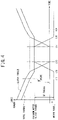
Figure 4 is a time chart showing changes in torque when clutch releasing and connecting speeds are changed in three steps in the speed-change assist control process of the automatic transmission control device according to the embodiment of the present invention. - An automatic transmission control device of an embodiment of the present invention is configured to: be provided to a hybrid vehicle including an engine, a motor, an automatic transmission that changes a speed of rotation of the engine and transmits the rotation to a drive shaft, and a clutch that releases or connects power transmission between the engine and the drive shaft; and include a control unit that controls the automatic transmission and the clutch to switch gear stages of the automatic transmission, the control unit, in a clutch releasing process during a speed change of the automatic transmission, changing a releasing speed of the clutch and causing the motor to output speed-change assist torque, at a timing according to an output state of torque of the motor at a start of the speed change of the automatic transmission.
- Thus, the automatic transmission control device according to the embodiment of the present invention can reduce variation in torque during a speed change and reduce a lag feeling of the speed change perceived by the driver.
- A hybrid vehicle provided with an automatic transmission control device according to an embodiment of the present invention will be described in detail below with reference to the drawings.
- In
Figure 1 , a hybrid vehicle 1 according to an embodiment of the present invention includes anengine 2 as an internal combustion engine, atransmission 3 as an automatic transmission, amotor 4, aninverter 5, a high-voltage battery 6, a low-voltage battery 7, and acontrol unit 8. - A plurality of cylinders are formed in the
engine 2. In the present embodiment, theengine 2 is configured to perform a series of four processes composed of an intake process, a compression process, an expansion process and an exhaust process for each cylinder. - A
starting device 21 is connected to theengine 2. Thestarting device 21 is connected to a crankshaft of theengine 2 via a belt (not shown). Thestarting device 21 rotates by being supplied with electric power to rotate the crankshaft and provide starting rotational force to theengine 2. - The
starting device 21 includes a starter or an integrated starter generator (ISG). The ISG has an electric motor function of rotating by being supplied with electric power to rotationally drive theengine 2 and an electric generator function of converting rotational force input from the crankshaft of theengine 2 into electric power. Both the starter and the ISG may be provided as thestarting device 21. - The
transmission 3 changes the speed of rotation output from theengine 2 and drivesdriving wheels 10 viadrive shafts 11. Thetransmission 3 includes a constant-mesh transmission mechanism (not shown) composed of a paralleled gear mechanism, and an actuator (not shown). - A dry-type single-
plate clutch 31 is provided between theengine 2 and thetransmission 3, and theclutch 31 connects and disconnects the power transmission between theengine 2 and thetransmission 3. - The
transmission 3 is configured as what is called an automated manual transmission (AMT), and the switching of the gear stages in the transmission mechanism and the connection and disconnection of theclutch 31 are performed by the actuator (not shown). - A
differential mechanism 32 is provided between thetransmission 3 and thedriving wheels 10. Thedifferential mechanism 32 and thedriving wheels 10 are connected bydrive shafts 11. - The
motor 4 is connected to thedifferential mechanism 32 via a reducer (not shown) such as a chain. Themotor 4 functions as an electric motor. Themotor 4 also functions as an electric generator and performs power generation as the hybrid vehicle 1 travels. - The
motor 4 is provided with atemperature sensor 41 for detecting the temperature of themotor 4. Thetemperature sensor 41 is connected to thecontrol unit 8. - Under control of the
control unit 8, theinverter 5 converts direct-current electric power supplied from the high-voltage battery 6 or the like into three-phase alternating-current electric power and supplies it to themotor 4. - Under control of the
control unit 8, theinverter 5 converts three-phase alternating-current electric power generated by themotor 4 into direct-current electric power. This direct-current electric power charges the high-voltage battery 6, for example. - The high-
voltage battery 6 is composed of a lithium-ion storage battery, for example. The high-voltage battery 6 supplies electric power to theinverter 5. - The high-
voltage battery 6 is provided with abattery state sensor 61. Thebattery state sensor 61 detects charge/discharge current, voltage, and battery temperature of the high-voltage battery 6. Thebattery state sensor 61 is connected to thecontrol unit 8. Thecontrol unit 8 can detect the amount of charge of the high-voltage battery 6 based on an output of thebattery state sensor 61. - The low-
voltage battery 7 is composed of a lead-acid battery, for example. The low-voltage battery 7 supplies electric power to an electrical load of the hybrid vehicle 1 such as thestarting device 21. - Thus, the hybrid vehicle 1 forms a parallel hybrid system capable of using power from both of the
engine 2 and themotor 4 for driving the vehicle, and travels by means of power output by at least one of theengine 2 and themotor 4. - The
control unit 8 is composed of a computer unit including a central processing unit (CPU), a random access memory (RAM), a read only memory (ROM), a flash memory for storing backup data or the like, an input port, and an output port. - The ROM of this computer unit stores a program for causing the computer unit to function as the
control unit 8, in addition to various constants, various maps and the like. - In other words, the CPU executes the program stored in the ROM by using the RAM as a workspace, so that the computer unit functions as the
control unit 8 in the present embodiment. - In addition to the
temperature sensor 41 and thebattery state sensor 61 mentioned above, various sensors including anaccelerator position sensor 81 and aclutch stroke sensor 82 are connected to the input port of thecontrol unit 8. - The
accelerator position sensor 81 detects the amount by which an accelerator pedal (not shown) is operated as an accelerator position. Theclutch stroke sensor 82 detects the degree of engagement of theclutch 31. - On the other hand, in addition to the
starting device 21, the actuator of thetransmission 3, and theinverter 5 mentioned above, various control objects including an injector (not shown) are connected to the output port of thecontrol unit 8. - In the present embodiment, the
control unit 8 calculates a driver-required torque required by the driver based on the accelerator position and the like. Thecontrol unit 8 controls theengine 2, thetransmission 3, theclutch 31, and themotor 4 such that the driver-required torque is output to thedriving wheels 10. - In addition, for example, the
control unit 8 controls thetransmission 3 and the clutch 31, based on a gear shift map for determining the gear stage of thetransmission 3 from the accelerator position and the vehicle speed, such that the gear stage of thetransmission 3 is changed when a shift line, which is a boundary line between adjacent gear stages, is crossed by a point obtained from the accelerator position and the vehicle speed. - In addition, the
control unit 8 causes themotor 4 to output regeneration torque and perform power generation during, for example, a deceleration of the hybrid vehicle 1. In addition, thecontrol unit 8 causes the ISG of the startingdevice 21 to perform power generation during, for example, a deceleration of the hybrid vehicle 1. Torque used for such power generation is referred to as power generation torque. - In addition, the
control unit 8 is configured to perform speed-change assist control of outputting assist torque from themotor 4 to the drivingwheels 10 in a period of time where the clutch 31 is released during a speed change. - The "period of time where the clutch 31 is released" refers to a period of time where complete engagement of the clutch 31 is removed (this period of time will hereinafter be referred to as an "incomplete engagement period"), and the incomplete engagement period includes what is called a half-clutch state. The half-clutch state refers to a state where friction members of the clutch 31 engage with each other in a slipping manner to transmit power.
- In a vehicle in which the clutch is provided in the power transmission path between the transmission mechanism and the engine, since no torque from the engine is transmitted to the driving wheels in the incomplete engagement period of the clutch during a speed change, loss of acceleration/deceleration feeling, i.e. what is called torque loss occurs, and a free-running feeling is caused by this torque loss.
- The speed-change assist control is to avoid the occurrence of the free-running feeling due to torque loss by outputting assist torque from the
motor 4 to the drivingwheels 10 in the incomplete engagement period of the clutch 31 during a speed change. - The
control unit 8 increases the releasing speed of the clutch 31 in a clutch releasing process during a speed change of thetransmission 3 and causes speed-change assist torque to be output from themotor 4 at a timing according to the output state of torque of themotor 4 at the start of the speed change. - For example, the
control unit 8 increases the releasing speed of the clutch 31 in the clutch releasing process during the speed change of thetransmission 3 and causes the speed-change assist torque to be output from themotor 4 at a timing according to the output state of power generation torque at the start of the speed change. Thecontrol unit 8 sets the releasing speed of the clutch 31 at the start of the speed change to a first speed, and sets the releasing speed of the clutch 31 to a second speed faster than the first speed at a timing according to the output state of regeneration torque of themotor 4 at the start of the speed change of thetransmission 3. - The power generation torque at the start of the speed change is power generation torque output at a predetermined timing after the
control unit 8 determines to perform the speed change and before the release of the clutch 31 is started, for example. Note that, in the present embodiment, the power generation torque at the start of the speed change is maintained even after the speed change starts, and the power generation torque at the start of the speed change is output even after the speed change ends. - The clutch releasing process refers to a period of time from when complete engagement of the clutch 31 starts to be removed to when the clutch 31 is completely released.
- The
control unit 8 increases the releasing speed of the clutch 31 and causes the speed-change assist torque to be output from themotor 4 when the clutch torque is decreased to predetermined torque in the clutch releasing process during the speed change. - The
control unit 8 increases the releasing speed of the clutch 31 and causes the speed-change assist torque to be output from themotor 4 when the clutch torque is decreased to GF torque, for example, which is torque obtained by summing maximum motor output torque, which is the maximum torque that can be output by themotor 4 at the start of the speed change, and the power generation torque output by themotor 4 at the start of the speed change, in the clutch releasing process during the speed change. - The clutch torque refers to the torque of an output shaft of the
transmission 3, which is output to thedifferential mechanism 32. - The power generation torque output by the
motor 4 refers to the regeneration torque output by themotor 4. The summation of the maximum motor output torque and the power generation torque output by themotor 4 is the addition of the absolute value of the regeneration torque output by themotor 4 to the maximum motor output torque. Alternatively, if torque of themotor 4 for driving the hybrid vehicle 1 is defined as positive torque, the regeneration torque output by themotor 4 is considered to be an opposite, that is negative torque, and therefore torque obtained by subtracting the regeneration torque output by themotor 4 at the start of the speed change from the maximum motor output torque is the GF torque. - The
control unit 8 calculates the maximum motor output torque based on the amount of charge of the high-voltage battery 6 or the state of heat generation of themotor 4. - For example, the
control unit 8 may calculate the maximum motor output torque at a predetermined period, and increase the clutch releasing speed and cause the speed-change assist torque to be output from themotor 4 at a point of time when the difference between the output torque of themotor 4 at the start of the speed change and the maximum motor output torque becomes equal to the clutch torque. - The
control unit 8 may increase the clutch releasing speed and cause the speed-change assist torque to be output from themotor 4 at a point of time when total torque becomes equal to the maximum motor output torque in the clutch releasing process during the speed change. - The total torque is the torque output to the
drive shafts 11, and the sum of the clutch torque and the motor torque. - The
control unit 8 causes themotor 4 to output, as the speed-change assist torque, torque obtained by subtracting the clutch torque from the maximum motor output torque, after starting to increase the releasing speed of the clutch 31 in the clutch releasing process during the speed change. In other words, thecontrol unit 8 causes themotor 4 to output, as the speed-change assist torque (regeneration torque), negative torque obtained by subtracting the clutch torque from the maximum motor output torque while the clutch torque is larger than the maximum motor output torque, and causes themotor 4 to output, as the speed-change assist torque, positive torque obtained by subtracting the clutch torque from the maximum motor output torque when the clutch torque becomes smaller than the maximum motor output torque. - The
control unit 8 sets the connecting speed of the clutch 31 to be faster than that of the clutch 31 after the clutch torque becomes greater than or equal to the GF torque until the clutch torque becomes equal to the GF torque, in a clutch connecting process during the speed change. - The clutch connecting process refers to a period of time from when the engagement of the clutch 31 starts after the switching of the gear stages of the transmission mechanism of the
transmission 3 to when the clutch 31 is completely engaged. - When the connecting speed of the clutch 31 until the clutch torque becomes equal to the GF torque is defined as a third speed and the connecting speed of the clutch 31 after the clutch torque becomes greater than or equal to the GF torque is defined as a fourth speed, the
control unit 8 sets the third speed to be faster than the fourth speed in the clutch connecting process during the speed change. - The
control unit 8, in the clutch connecting process during the speed change, causes themotor 4 to output, as the speed-change assist torque, torque obtained by subtracting the clutch torque from the maximum motor output torque, after starting the engagement of the clutch 31. Then, after the clutch torque becomes equal to the GF torque and the connecting speed of the clutch is decreased, the regeneration torque output by themotor 4 at the start of the speed change is output by themotor 4. In other words, thecontrol unit 8 causes themotor 4 to output, as the speed-change assist torque, positive torque obtained by subtracting the clutch torque from the maximum motor output torque while the clutch torque is smaller than the maximum motor output torque, and causes themotor 4 to output, as the speed-change assist torque (regeneration torque), negative torque obtained by subtracting the clutch torque from the total torque when the clutch torque becomes larger than the maximum motor output torque. - A speed-change assist control process performed by the automatic transmission control device according to the present embodiment configured as described above will be described with reference to
Figure 2 . Note that the speed-change assist control process described below is started when thecontrol unit 8 starts operation, and is performed at a preset time interval. - In step S1, the
control unit 8 detects the amount of charge of the high-voltage battery 6. After performing the process of step S1, thecontrol unit 8 performs the process of step S2. - In step S2, the
control unit 8 determines whether to perform a speed change. For example, thecontrol unit 8 determines whether to perform a speed change based on the vehicle speed, the engine rotation rate, and the like. - When determining to perform a speed change, the
control unit 8 performs the process of step S3. When determining not to perform a speed change, thecontrol unit 8 ends the speed-change assist control process. - In step S3, the
control unit 8 determines whether regeneration by themotor 4 is currently performed. - When determining that regeneration by the
motor 4 is being performed, thecontrol unit 8 performs the process of step S4. When determining that regeneration by themotor 4 is not being performed, thecontrol unit 8 ends the speed-change assist control process. - In step S4, the
control unit 8 calculates the maximum motor output torque from the amount of charge of the high-voltage battery 6. After performing the process of step S4, thecontrol unit 8 performs the process of step S5. - In step S5, the
control unit 8 subtracts the current regeneration torque from the maximum motor output torque in order to calculate the GF torque. After performing the process of step S5, thecontrol unit 8 performs the process of step S6. - In step S6, the
control unit 8 starts to release the clutch 31 at the first speed. After performing the process of step S6, thecontrol unit 8 performs the process of step S7. - In step S7, the
control unit 8 determines whether the clutch torque is equal to the GF torque. - When determining that the clutch torque is equal to the GF torque, the
control unit 8 performs the process of step S8. When determining that the clutch torque is not equal to the GF torque, thecontrol unit 8 repeats the process of step S7. - In step S8, the
control unit 8 starts to release the clutch 31 at the second speed. After performing the process of step S8, thecontrol unit 8 performs the process of step S9. - In step S9, the
control unit 8 determines whether switching of the gear stages is completed. When determining that the switching of the gear stages is completed, thecontrol unit 8 performs the process of step S10. When determining that the switching of the gear stages is not completed, thecontrol unit 8 repeats the process of step S9. - In step S10, the
control unit 8 starts to engage the clutch 31 at the third speed. After performing the process of step S10, thecontrol unit 8 performs the process of step S11. - In step S11, the
control unit 8 determines whether the clutch torque is equal to the GF torque. - When determining that the clutch torque is equal to the GF torque, the
control unit 8 performs the process of step S12. When determining that the clutch torque is not equal to the GF torque, thecontrol unit 8 repeats the process of step S11. - In step S12, the
control unit 8 starts to engage the clutch 31 at the fourth speed. After performing the process of step S12, thecontrol unit 8 ends the speed-change assist control process. - Operations in this speed-change assist control process will be described with reference to
Figure 3 . - When a speed change process is started and removal of complete engagement of the clutch 31 is started, the clutch 31 is released at the first speed, the clutch torque decreases, and the total torque transmitted to the
drive shafts 11 also decreases. At this time, since the clutch torque is larger than the GF torque, the output of the speed-change assist torque by themotor 4 is not performed, and the regeneration torque at the start of the speed change continues to be output. - When the clutch torque becomes equal to the GF torque at time t1, the releasing speed of the clutch 31 is increased to the second speed, which is faster than the first speed, and torque obtained by subtracting the clutch torque from the maximum motor output torque is output from the
motor 4 as the speed-change assist torque. - When the clutch 31 is completely released at time t2, switching of the gear stages of the transmission mechanism of the
transmission 3 is started, during which motor assist by themotor 4 at the maximum motor output torque is performed. - When the switching of the gear stages of the transmission mechanism of the
transmission 3 is completed at time t3, engagement of the clutch 31 is started at the third speed, which is substantially equal to the second speed, for example, and the assist torque from themotor 4 is decreased such that its sum with the clutch torque becomes equal to the maximum motor output torque. - When the clutch torque becomes equal to the GF torque at time t4, the connecting speed of the clutch 31 is decreased to the fourth speed, and the output of the
motor 4 is maintained at the regeneration torque output by themotor 4 at the start of the speed change. - Thus, in the present embodiment, the
control unit 8 increases the releasing speed of the clutch 31 in a clutch releasing process during a speed change of thetransmission 3 and causes themotor 4 to output the speed-change assist torque, at a timing according to the output state of torque of themotor 4 at the start of the speed change. - In this manner, the timing for increasing the releasing speed of the clutch 31 in the clutch releasing process is changed according to the output state of torque of the
motor 4 at the start of the speed change. Thus, it is possible to suppress vibration of the vehicle at the start of the speed change by switching between the clutch torque and the motor torque while the torque that can be output by themotor 4 is available. - In addition, the
control unit 8 increases the releasing speed of the clutch 31 in a clutch releasing process during a speed change of thetransmission 3 and causes themotor 4 to output the speed-change assist torque, at a timing according to the output state of power generation torque of themotor 4 at the start of the speed change. - In this manner, the timing for increasing the releasing speed of the clutch 31 in the clutch releasing process is changed according to the output state of power generation torque of the
motor 4 at the start of the speed change. Thus, it is possible to increase the releasing speed of the clutch 31 at a timing suitable to the power generation torque of themotor 4 at the start of the speed change, and reduce variation in torque during the speed change. - In addition, since the releasing speed of the clutch 31 is increased, it is possible to shorten the speed change time.
- Since the speed change time can be shortened, it is possible to reduce the lag feeling during the speed change.
- In addition, since the releasing speed of the clutch 31 is increased, it is possible to shorten assist time of the
motor 4 during the speed change and reduce energy consumption of themotor 4. - In addition, the
control unit 8 increases the releasing speed of the clutch 31 and causes the speed-change assist torque to be output from themotor 4 when the clutch torque is decreased to predetermined torque in the clutch releasing process during the speed change of thetransmission 3. - In this manner, when the clutch torque is decreased to the predetermined torque, the releasing speed of the clutch 31 is increased, and the speed-change assist torque is output from the
motor 4. Thus, it is possible to increase the releasing speed of the clutch 31 at a timing when the clutch torque is decreased to the predetermined torque, reduce variation in torque during the speed change, and reduce energy consumption of themotor 4. - In addition, the
control unit 8 increases the releasing speed of the clutch 31 and causes the speed-change assist torque to be output from themotor 4 when the clutch torque is decreased to the GF torque in the clutch releasing process during the speed change of thetransmission 3. - In this manner, when the clutch torque is decreased to the GF torque, the releasing speed of the clutch 31 is increased, and the speed-change assist torque is output from the
motor 4. Thus, it is possible to shorten the speed change time as compared to the case of increasing the releasing speed of the clutch 31 after the clutch torque is decreased to the maximum motor output torque, and reduce the lag feeling during the speed change. In addition, since the releasing speed of the clutch 31 is increased at a timing when themotor 4 can output the assist torque, it is possible to reduce variation in torque during the speed change. In addition, it is possible to shorten assist time of themotor 4 and reduce energy consumption of themotor 4. - In addition, the
control unit 8 increases the releasing speed of the clutch 31 and causes the speed-change assist torque to be output from themotor 4 when the total torque is decreased to the maximum motor output torque in the clutch releasing process during the speed change of thetransmission 3. - In this manner, when the total torque is decreased to the maximum motor output torque, the releasing speed of the clutch 31 is increased, and the speed-change assist torque is output from the
motor 4. Thus, it is possible to shorten the speed change time as compared to the case of increasing the releasing speed of the clutch 31 after the clutch torque is decreased to the maximum motor output torque, and reduce the lag feeling during the speed change. In addition, since the releasing speed of the clutch 31 is increased at a timing when the assist torque that can be output by themotor 4 is available, it is possible to reduce variation in torque during the speed change. In addition, it is possible to shorten assist time of themotor 4 and reduce energy consumption of themotor 4. - Note that, although the releasing speed of the clutch 31 and the connecting speed of the clutch 31 are changed in two steps in the present embodiment, they may be changed in more than two steps.
Figure 4 shows a case of changing the releasing and connecting speeds of the clutch 31 in three steps. - In
Figure 4 , when a speed change process is started and removal of complete engagement of the clutch 31 is started, the clutch 31 is released at the first speed, the clutch torque decreases, and the torque transmitted to thedrive shafts 11 also decreases. At this time, since the clutch torque is larger than the GF torque, the output of the assist torque by themotor 4 is not performed, and the regeneration torque at the start of the speed change continues to be output. - When the total torque becomes equal to the GF torque at time t11, the releasing speed of the clutch 31 is increased to a speed faster than the first speed and slower than the second speed.
- When the clutch torque becomes equal to the GF torque at time t12, the releasing speed of the clutch 31 is increased to the second speed, which is faster than the first speed, and torque obtained by subtracting the clutch torque from the maximum motor output torque is output from the
motor 4 as the speed-change assist torque. - When the clutch 31 is completely released at time t13, switching of the gear stages of the transmission mechanism of the
transmission 3 is started, during which motor assist by themotor 4 at the maximum motor output torque is performed. - When the switching of the gear stages of the transmission mechanism of the
transmission 3 is completed at time t14, engagement of the clutch 31 is started at the third speed, which is substantially equal to the second speed, for example, and the assist torque from themotor 4 is decreased such that its sum with the clutch torque becomes equal to the maximum motor output torque. - When the clutch torque becomes equal to the GF torque at time t15, the connecting speed of the clutch 31 is decreased to a speed slower than the third speed and faster than the fourth speed, and the assist torque from the
motor 4 is maintained at the regeneration torque output by themotor 4 at the start of the speed change. - When the total torque becomes equal to the GF torque at time t16, the connecting speed of the clutch 31 is decreased to the fourth speed.
- In this manner, it is possible to shorten the speed change time, and reduce the lag feeling during the speed change while reducing variation in torque during the speed change.
- Although an example where the
control unit 8 performs various determinations and calculations based on various pieces of sensor information has been described in the present embodiment, there is no limitation thereto, and the hybrid vehicle 1 may include a communication unit capable of communicating with an external device such as an external server so that the various determinations and calculations are performed by the external device based on detection information of various sensors transmitted from the communication unit, the communication unit receives those determination and calculation results, and various control operations are performed by using those received determination and calculation results. - Although the embodiment of the present invention has been disclosed, it is obvious that those skilled in the art can make changes without departing from the scope of the present invention. It is intended that all such modifications and equivalents are encompassed by the following claims.
- 1...hybrid vehicle, 2...engine, 3...transmission (automatic transmission), 4...motor, 6...high-voltage battery (battery), 8... control unit, 11... drive shaft, 31... clutch, 41...temperature sensor, 61...battery state sensor, 81...accelerator position sensor, 82...clutch stroke sensor
Claims (5)
- An automatic transmission control device provided to a hybrid vehicle (1) including an engine (2), a motor (4), an automatic transmission (3) that changes a speed of rotation of the engine (2) and transmits the rotation to a drive shaft (11), and a clutch (31) that releases or connects power transmission between the engine (2) and the drive shaft (11),the automatic transmission control device comprising a control unit (8) that controls the automatic transmission (3) and the clutch (31) to switch gear stages of the automatic transmission (3), whereinthe control unit (8), in a clutch releasing process during a speed change of the automatic transmission (3), changes a releasing speed of the clutch (31) and causes the motor (4) to output a speed-change assist torque, at a timing according to an output state of torque of the motor (4) at a start of the speed change of the automatic transmission (3).
- The automatic transmission control device as claimed in claim 1, wherein the control unit (8) changes the releasing speed of the clutch (31) and causes the motor (4) to output the speed-change assist torque, at a timing according to an output state of power generation torque of the motor (4) at the start of the speed change.
- The automatic transmission control device as claimed in claim 1 or 2, wherein the control unit (8), in the clutch releasing process, increases the releasing speed of the clutch (31) and causes the motor (4) to output the speed-change assist torque when a clutch torque output from the automatic transmission (3) decreases to a predetermined torque.
- The automatic transmission control device as claimed in claim 3, wherein the control unit (8), in the clutch releasing process, increases the releasing speed of the clutch (31) and causes the motor (4) to output the speed-change assist torque when the clutch torque decreases to a torque obtained by summing a maximum motor output torque and the power generation torque.
- The automatic transmission control device as claimed in claim 1 or 2, wherein the control unit (8), in the clutch releasing process, increases the releasing speed of the clutch (31) and causes the motor (4) to output the speed-change assist torque when a torque output to the drive shaft (11) decreases to a maximum motor output torque.
Applications Claiming Priority (1)
| Application Number | Priority Date | Filing Date | Title |
|---|---|---|---|
| JP2020159784A JP7559465B2 (en) | 2020-09-24 | 2020-09-24 | Automatic transmission control device |
Publications (2)
| Publication Number | Publication Date |
|---|---|
| EP3974224A1 true EP3974224A1 (en) | 2022-03-30 |
| EP3974224B1 EP3974224B1 (en) | 2025-01-01 |
Family
ID=77595468
Family Applications (1)
| Application Number | Title | Priority Date | Filing Date |
|---|---|---|---|
| EP21194406.1A Active EP3974224B1 (en) | 2020-09-24 | 2021-09-01 | Automatic transmission control device |
Country Status (3)
| Country | Link |
|---|---|
| EP (1) | EP3974224B1 (en) |
| JP (1) | JP7559465B2 (en) |
| HU (1) | HUE070791T2 (en) |
Citations (3)
| Publication number | Priority date | Publication date | Assignee | Title |
|---|---|---|---|---|
| US20160137188A1 (en) * | 2014-11-18 | 2016-05-19 | Saic Motor Corporation Limited | Control systems and methods for transmission of hybrid power vehicle |
| DE102017114999A1 (en) * | 2016-07-07 | 2018-01-11 | Suzuki Motor Corporation | Gear change control for vehicles |
| JP2019055771A (en) | 2017-09-07 | 2019-04-11 | マニェティ・マレリ・ソシエタ・ペル・アチオニMAGNETI MARELLI S.p.A. | Method for controlling gear shift phase in hybrid vehicle provided with automated manual transmission, and corresponding transmission system for hybrid vehicle |
-
2020
- 2020-09-24 JP JP2020159784A patent/JP7559465B2/en active Active
-
2021
- 2021-09-01 EP EP21194406.1A patent/EP3974224B1/en active Active
- 2021-09-01 HU HUE21194406A patent/HUE070791T2/en unknown
Patent Citations (3)
| Publication number | Priority date | Publication date | Assignee | Title |
|---|---|---|---|---|
| US20160137188A1 (en) * | 2014-11-18 | 2016-05-19 | Saic Motor Corporation Limited | Control systems and methods for transmission of hybrid power vehicle |
| DE102017114999A1 (en) * | 2016-07-07 | 2018-01-11 | Suzuki Motor Corporation | Gear change control for vehicles |
| JP2019055771A (en) | 2017-09-07 | 2019-04-11 | マニェティ・マレリ・ソシエタ・ペル・アチオニMAGNETI MARELLI S.p.A. | Method for controlling gear shift phase in hybrid vehicle provided with automated manual transmission, and corresponding transmission system for hybrid vehicle |
Also Published As
| Publication number | Publication date |
|---|---|
| JP7559465B2 (en) | 2024-10-02 |
| JP2022053143A (en) | 2022-04-05 |
| HUE070791T2 (en) | 2025-07-28 |
| EP3974224B1 (en) | 2025-01-01 |
Similar Documents
| Publication | Publication Date | Title |
|---|---|---|
| RU2663260C2 (en) | Clutch control device for hybrid vehicle | |
| EP2018305B1 (en) | Driving system for hybrid vehicle | |
| CN105579269B (en) | The start-control device and method for starting-controlling of hybrid vehicle | |
| RU2653656C2 (en) | Failure determination device of hybrid vehicle and failure determination method thereof | |
| EP3045364B1 (en) | Controller for hybrid vehicle | |
| US10336314B2 (en) | Hybrid powertrain system | |
| JP2000125414A (en) | Hybrid vehicle control device | |
| US9180877B2 (en) | Control device | |
| EP4242496A1 (en) | Control device of vehicle | |
| JP4707750B2 (en) | Vehicle transmission control device | |
| JP6561490B2 (en) | Drive control device | |
| EP3974224B1 (en) | Automatic transmission control device | |
| EP3974226B1 (en) | A hybrid vehicle comprising an automatic transmission control device | |
| EP4227133B1 (en) | Control device of hybrid vehicle | |
| EP3974225B1 (en) | Control device for hybrid vehicle | |
| JP7334493B2 (en) | Drive system for hybrid vehicle | |
| JP7513882B2 (en) | Automatic transmission control device | |
| JP7513881B2 (en) | Automatic transmission control device | |
| JP2018069947A (en) | Drive control device of hybrid vehicle | |
| JP7791644B2 (en) | Motor assist control device for hybrid vehicles | |
| EP4234985A1 (en) | System and method for shifting gears in a gearbox of a drivetrain in a vehicle | |
| JP2025033343A (en) | Transmission control device for hybrid vehicle | |
| JP7338553B2 (en) | Hybrid vehicle control device | |
| JP2025086158A (en) | Vehicle control device | |
| JP2024085020A (en) | Hybrid vehicle control device |
Legal Events
| Date | Code | Title | Description |
|---|---|---|---|
| PUAI | Public reference made under article 153(3) epc to a published international application that has entered the european phase |
Free format text: ORIGINAL CODE: 0009012 |
|
| STAA | Information on the status of an ep patent application or granted ep patent |
Free format text: STATUS: REQUEST FOR EXAMINATION WAS MADE |
|
| 17P | Request for examination filed |
Effective date: 20210901 |
|
| AK | Designated contracting states |
Kind code of ref document: A1 Designated state(s): AL AT BE BG CH CY CZ DE DK EE ES FI FR GB GR HR HU IE IS IT LI LT LU LV MC MK MT NL NO PL PT RO RS SE SI SK SM TR |
|
| REG | Reference to a national code |
Ref country code: DE Ref legal event code: R079 Free format text: PREVIOUS MAIN CLASS: B60K0006387000 Ipc: B60K0001000000 Ref country code: DE Ref legal event code: R079 Ref document number: 602021024137 Country of ref document: DE Free format text: PREVIOUS MAIN CLASS: B60K0006387000 Ipc: B60K0001000000 |
|
| RIC1 | Information provided on ipc code assigned before grant |
Ipc: B60K 6/547 20071001ALI20240626BHEP Ipc: B60K 6/48 20071001ALI20240626BHEP Ipc: B60K 6/387 20071001ALI20240626BHEP Ipc: B60W 20/10 20160101ALI20240626BHEP Ipc: B60W 10/11 20120101ALI20240626BHEP Ipc: B60W 10/08 20060101ALI20240626BHEP Ipc: B60W 10/06 20060101ALI20240626BHEP Ipc: B60W 10/02 20060101ALI20240626BHEP Ipc: B60W 20/30 20160101ALI20240626BHEP Ipc: B60W 30/19 20120101ALI20240626BHEP Ipc: B60W 30/18 20120101ALI20240626BHEP Ipc: B60W 20/15 20160101ALI20240626BHEP Ipc: B60W 20/14 20160101ALI20240626BHEP Ipc: B60W 20/11 20160101ALI20240626BHEP Ipc: B60K 1/00 20060101AFI20240626BHEP |
|
| GRAP | Despatch of communication of intention to grant a patent |
Free format text: ORIGINAL CODE: EPIDOSNIGR1 |
|
| STAA | Information on the status of an ep patent application or granted ep patent |
Free format text: STATUS: GRANT OF PATENT IS INTENDED |
|
| INTG | Intention to grant announced |
Effective date: 20240903 |
|
| GRAS | Grant fee paid |
Free format text: ORIGINAL CODE: EPIDOSNIGR3 |
|
| GRAA | (expected) grant |
Free format text: ORIGINAL CODE: 0009210 |
|
| STAA | Information on the status of an ep patent application or granted ep patent |
Free format text: STATUS: THE PATENT HAS BEEN GRANTED |
|
| AK | Designated contracting states |
Kind code of ref document: B1 Designated state(s): AL AT BE BG CH CY CZ DE DK EE ES FI FR GB GR HR HU IE IS IT LI LT LU LV MC MK MT NL NO PL PT RO RS SE SI SK SM TR |
|
| REG | Reference to a national code |
Ref country code: GB Ref legal event code: FG4D |
|
| REG | Reference to a national code |
Ref country code: CH Ref legal event code: EP |
|
| REG | Reference to a national code |
Ref country code: DE Ref legal event code: R096 Ref document number: 602021024137 Country of ref document: DE |
|
| REG | Reference to a national code |
Ref country code: IE Ref legal event code: FG4D |
|
| REG | Reference to a national code |
Ref country code: LT Ref legal event code: MG9D |
|
| REG | Reference to a national code |
Ref country code: NL Ref legal event code: MP Effective date: 20250101 |
|
| REG | Reference to a national code |
Ref country code: AT Ref legal event code: MK05 Ref document number: 1755899 Country of ref document: AT Kind code of ref document: T Effective date: 20250101 |
|
| PG25 | Lapsed in a contracting state [announced via postgrant information from national office to epo] |
Ref country code: NL Free format text: LAPSE BECAUSE OF FAILURE TO SUBMIT A TRANSLATION OF THE DESCRIPTION OR TO PAY THE FEE WITHIN THE PRESCRIBED TIME-LIMIT Effective date: 20250101 |
|
| PG25 | Lapsed in a contracting state [announced via postgrant information from national office to epo] |
Ref country code: FI Free format text: LAPSE BECAUSE OF FAILURE TO SUBMIT A TRANSLATION OF THE DESCRIPTION OR TO PAY THE FEE WITHIN THE PRESCRIBED TIME-LIMIT Effective date: 20250101 |
|
| PG25 | Lapsed in a contracting state [announced via postgrant information from national office to epo] |
Ref country code: PL Free format text: LAPSE BECAUSE OF FAILURE TO SUBMIT A TRANSLATION OF THE DESCRIPTION OR TO PAY THE FEE WITHIN THE PRESCRIBED TIME-LIMIT Effective date: 20250101 |
|
| PG25 | Lapsed in a contracting state [announced via postgrant information from national office to epo] |
Ref country code: ES Free format text: LAPSE BECAUSE OF FAILURE TO SUBMIT A TRANSLATION OF THE DESCRIPTION OR TO PAY THE FEE WITHIN THE PRESCRIBED TIME-LIMIT Effective date: 20250101 |
|
| PG25 | Lapsed in a contracting state [announced via postgrant information from national office to epo] |
Ref country code: NO Free format text: LAPSE BECAUSE OF FAILURE TO SUBMIT A TRANSLATION OF THE DESCRIPTION OR TO PAY THE FEE WITHIN THE PRESCRIBED TIME-LIMIT Effective date: 20250401 Ref country code: IS Free format text: LAPSE BECAUSE OF FAILURE TO SUBMIT A TRANSLATION OF THE DESCRIPTION OR TO PAY THE FEE WITHIN THE PRESCRIBED TIME-LIMIT Effective date: 20250501 |
|
| PG25 | Lapsed in a contracting state [announced via postgrant information from national office to epo] |
Ref country code: HR Free format text: LAPSE BECAUSE OF FAILURE TO SUBMIT A TRANSLATION OF THE DESCRIPTION OR TO PAY THE FEE WITHIN THE PRESCRIBED TIME-LIMIT Effective date: 20250101 |
|
| PG25 | Lapsed in a contracting state [announced via postgrant information from national office to epo] |
Ref country code: LV Free format text: LAPSE BECAUSE OF FAILURE TO SUBMIT A TRANSLATION OF THE DESCRIPTION OR TO PAY THE FEE WITHIN THE PRESCRIBED TIME-LIMIT Effective date: 20250101 Ref country code: PT Free format text: LAPSE BECAUSE OF FAILURE TO SUBMIT A TRANSLATION OF THE DESCRIPTION OR TO PAY THE FEE WITHIN THE PRESCRIBED TIME-LIMIT Effective date: 20250502 |
|
| PG25 | Lapsed in a contracting state [announced via postgrant information from national office to epo] |
Ref country code: GR Free format text: LAPSE BECAUSE OF FAILURE TO SUBMIT A TRANSLATION OF THE DESCRIPTION OR TO PAY THE FEE WITHIN THE PRESCRIBED TIME-LIMIT Effective date: 20250402 Ref country code: BG Free format text: LAPSE BECAUSE OF FAILURE TO SUBMIT A TRANSLATION OF THE DESCRIPTION OR TO PAY THE FEE WITHIN THE PRESCRIBED TIME-LIMIT Effective date: 20250101 |
|
| PG25 | Lapsed in a contracting state [announced via postgrant information from national office to epo] |
Ref country code: AT Free format text: LAPSE BECAUSE OF FAILURE TO SUBMIT A TRANSLATION OF THE DESCRIPTION OR TO PAY THE FEE WITHIN THE PRESCRIBED TIME-LIMIT Effective date: 20250101 |
|
| PG25 | Lapsed in a contracting state [announced via postgrant information from national office to epo] |
Ref country code: CZ Free format text: LAPSE BECAUSE OF FAILURE TO SUBMIT A TRANSLATION OF THE DESCRIPTION OR TO PAY THE FEE WITHIN THE PRESCRIBED TIME-LIMIT Effective date: 20250101 |
|
| REG | Reference to a national code |
Ref country code: HU Ref legal event code: AG4A Ref document number: E070791 Country of ref document: HU |
|
| PG25 | Lapsed in a contracting state [announced via postgrant information from national office to epo] |
Ref country code: SE Free format text: LAPSE BECAUSE OF FAILURE TO SUBMIT A TRANSLATION OF THE DESCRIPTION OR TO PAY THE FEE WITHIN THE PRESCRIBED TIME-LIMIT Effective date: 20250101 |
|
| REG | Reference to a national code |
Ref country code: DE Ref legal event code: R097 Ref document number: 602021024137 Country of ref document: DE |
|
| PG25 | Lapsed in a contracting state [announced via postgrant information from national office to epo] |
Ref country code: SM Free format text: LAPSE BECAUSE OF FAILURE TO SUBMIT A TRANSLATION OF THE DESCRIPTION OR TO PAY THE FEE WITHIN THE PRESCRIBED TIME-LIMIT Effective date: 20250101 |
|
| PG25 | Lapsed in a contracting state [announced via postgrant information from national office to epo] |
Ref country code: DK Free format text: LAPSE BECAUSE OF FAILURE TO SUBMIT A TRANSLATION OF THE DESCRIPTION OR TO PAY THE FEE WITHIN THE PRESCRIBED TIME-LIMIT Effective date: 20250101 |
|
| PGFP | Annual fee paid to national office [announced via postgrant information from national office to epo] |
Ref country code: DE Payment date: 20250814 Year of fee payment: 5 |
|
| PG25 | Lapsed in a contracting state [announced via postgrant information from national office to epo] |
Ref country code: IT Free format text: LAPSE BECAUSE OF FAILURE TO SUBMIT A TRANSLATION OF THE DESCRIPTION OR TO PAY THE FEE WITHIN THE PRESCRIBED TIME-LIMIT Effective date: 20250101 |
|
| PGFP | Annual fee paid to national office [announced via postgrant information from national office to epo] |
Ref country code: HU Payment date: 20250827 Year of fee payment: 5 |
|
| PGFP | Annual fee paid to national office [announced via postgrant information from national office to epo] |
Ref country code: FR Payment date: 20250925 Year of fee payment: 5 |
|
| PG25 | Lapsed in a contracting state [announced via postgrant information from national office to epo] |
Ref country code: EE Free format text: LAPSE BECAUSE OF FAILURE TO SUBMIT A TRANSLATION OF THE DESCRIPTION OR TO PAY THE FEE WITHIN THE PRESCRIBED TIME-LIMIT Effective date: 20250101 |
|
| PG25 | Lapsed in a contracting state [announced via postgrant information from national office to epo] |
Ref country code: RO Free format text: LAPSE BECAUSE OF FAILURE TO SUBMIT A TRANSLATION OF THE DESCRIPTION OR TO PAY THE FEE WITHIN THE PRESCRIBED TIME-LIMIT Effective date: 20250101 |
|
| PG25 | Lapsed in a contracting state [announced via postgrant information from national office to epo] |
Ref country code: SK Free format text: LAPSE BECAUSE OF FAILURE TO SUBMIT A TRANSLATION OF THE DESCRIPTION OR TO PAY THE FEE WITHIN THE PRESCRIBED TIME-LIMIT Effective date: 20250101 |
|
| PLBE | No opposition filed within time limit |
Free format text: ORIGINAL CODE: 0009261 |
|
| STAA | Information on the status of an ep patent application or granted ep patent |
Free format text: STATUS: NO OPPOSITION FILED WITHIN TIME LIMIT |
|
| REG | Reference to a national code |
Ref country code: CH Ref legal event code: L10 Free format text: ST27 STATUS EVENT CODE: U-0-0-L10-L00 (AS PROVIDED BY THE NATIONAL OFFICE) Effective date: 20251112 |
|
| 26N | No opposition filed |
Effective date: 20251002 |
|
| REG | Reference to a national code |
Ref country code: CH Ref legal event code: H13 Free format text: ST27 STATUS EVENT CODE: U-0-0-H10-H13 (AS PROVIDED BY THE NATIONAL OFFICE) Effective date: 20260425 |