EP3974191A1 - Liquid discharge head, liquid discharge device, and liquid discharge apparatus - Google Patents
Liquid discharge head, liquid discharge device, and liquid discharge apparatus Download PDFInfo
- Publication number
- EP3974191A1 EP3974191A1 EP21197164.3A EP21197164A EP3974191A1 EP 3974191 A1 EP3974191 A1 EP 3974191A1 EP 21197164 A EP21197164 A EP 21197164A EP 3974191 A1 EP3974191 A1 EP 3974191A1
- Authority
- EP
- European Patent Office
- Prior art keywords
- liquid discharge
- liquid
- oxide film
- silicon layer
- silicon
- Prior art date
- Legal status (The legal status is an assumption and is not a legal conclusion. Google has not performed a legal analysis and makes no representation as to the accuracy of the status listed.)
- Granted
Links
Images





Classifications
-
- B—PERFORMING OPERATIONS; TRANSPORTING
- B41—PRINTING; LINING MACHINES; TYPEWRITERS; STAMPS
- B41J—TYPEWRITERS; SELECTIVE PRINTING MECHANISMS, i.e. MECHANISMS PRINTING OTHERWISE THAN FROM A FORME; CORRECTION OF TYPOGRAPHICAL ERRORS
- B41J2/00—Typewriters or selective printing mechanisms characterised by the printing or marking process for which they are designed
- B41J2/005—Typewriters or selective printing mechanisms characterised by the printing or marking process for which they are designed characterised by bringing liquid or particles selectively into contact with a printing material
- B41J2/01—Ink jet
- B41J2/135—Nozzles
- B41J2/14—Structure thereof only for on-demand ink jet heads
- B41J2/1433—Structure of nozzle plates
-
- B—PERFORMING OPERATIONS; TRANSPORTING
- B41—PRINTING; LINING MACHINES; TYPEWRITERS; STAMPS
- B41J—TYPEWRITERS; SELECTIVE PRINTING MECHANISMS, i.e. MECHANISMS PRINTING OTHERWISE THAN FROM A FORME; CORRECTION OF TYPOGRAPHICAL ERRORS
- B41J2/00—Typewriters or selective printing mechanisms characterised by the printing or marking process for which they are designed
- B41J2/005—Typewriters or selective printing mechanisms characterised by the printing or marking process for which they are designed characterised by bringing liquid or particles selectively into contact with a printing material
- B41J2/01—Ink jet
-
- B—PERFORMING OPERATIONS; TRANSPORTING
- B41—PRINTING; LINING MACHINES; TYPEWRITERS; STAMPS
- B41J—TYPEWRITERS; SELECTIVE PRINTING MECHANISMS, i.e. MECHANISMS PRINTING OTHERWISE THAN FROM A FORME; CORRECTION OF TYPOGRAPHICAL ERRORS
- B41J2/00—Typewriters or selective printing mechanisms characterised by the printing or marking process for which they are designed
- B41J2/005—Typewriters or selective printing mechanisms characterised by the printing or marking process for which they are designed characterised by bringing liquid or particles selectively into contact with a printing material
- B41J2/01—Ink jet
- B41J2/135—Nozzles
- B41J2/16—Production of nozzles
- B41J2/1607—Production of print heads with piezoelectric elements
- B41J2/1612—Production of print heads with piezoelectric elements of stacked structure type, deformed by compression/extension and disposed on a diaphragm
-
- B—PERFORMING OPERATIONS; TRANSPORTING
- B41—PRINTING; LINING MACHINES; TYPEWRITERS; STAMPS
- B41J—TYPEWRITERS; SELECTIVE PRINTING MECHANISMS, i.e. MECHANISMS PRINTING OTHERWISE THAN FROM A FORME; CORRECTION OF TYPOGRAPHICAL ERRORS
- B41J2/00—Typewriters or selective printing mechanisms characterised by the printing or marking process for which they are designed
- B41J2/005—Typewriters or selective printing mechanisms characterised by the printing or marking process for which they are designed characterised by bringing liquid or particles selectively into contact with a printing material
- B41J2/01—Ink jet
- B41J2/135—Nozzles
- B41J2/14—Structure thereof only for on-demand ink jet heads
- B41J2/14201—Structure of print heads with piezoelectric elements
- B41J2/14233—Structure of print heads with piezoelectric elements of film type, deformed by bending and disposed on a diaphragm
-
- B—PERFORMING OPERATIONS; TRANSPORTING
- B41—PRINTING; LINING MACHINES; TYPEWRITERS; STAMPS
- B41J—TYPEWRITERS; SELECTIVE PRINTING MECHANISMS, i.e. MECHANISMS PRINTING OTHERWISE THAN FROM A FORME; CORRECTION OF TYPOGRAPHICAL ERRORS
- B41J2/00—Typewriters or selective printing mechanisms characterised by the printing or marking process for which they are designed
- B41J2/005—Typewriters or selective printing mechanisms characterised by the printing or marking process for which they are designed characterised by bringing liquid or particles selectively into contact with a printing material
- B41J2/01—Ink jet
- B41J2/135—Nozzles
- B41J2/14—Structure thereof only for on-demand ink jet heads
- B41J2/14201—Structure of print heads with piezoelectric elements
- B41J2/14274—Structure of print heads with piezoelectric elements of stacked structure type, deformed by compression/extension and disposed on a diaphragm
-
- B—PERFORMING OPERATIONS; TRANSPORTING
- B41—PRINTING; LINING MACHINES; TYPEWRITERS; STAMPS
- B41J—TYPEWRITERS; SELECTIVE PRINTING MECHANISMS, i.e. MECHANISMS PRINTING OTHERWISE THAN FROM A FORME; CORRECTION OF TYPOGRAPHICAL ERRORS
- B41J2/00—Typewriters or selective printing mechanisms characterised by the printing or marking process for which they are designed
- B41J2/005—Typewriters or selective printing mechanisms characterised by the printing or marking process for which they are designed characterised by bringing liquid or particles selectively into contact with a printing material
- B41J2/01—Ink jet
- B41J2/135—Nozzles
- B41J2/16—Production of nozzles
- B41J2/162—Manufacturing of the nozzle plates
-
- B—PERFORMING OPERATIONS; TRANSPORTING
- B41—PRINTING; LINING MACHINES; TYPEWRITERS; STAMPS
- B41J—TYPEWRITERS; SELECTIVE PRINTING MECHANISMS, i.e. MECHANISMS PRINTING OTHERWISE THAN FROM A FORME; CORRECTION OF TYPOGRAPHICAL ERRORS
- B41J2/00—Typewriters or selective printing mechanisms characterised by the printing or marking process for which they are designed
- B41J2/005—Typewriters or selective printing mechanisms characterised by the printing or marking process for which they are designed characterised by bringing liquid or particles selectively into contact with a printing material
- B41J2/01—Ink jet
- B41J2/135—Nozzles
- B41J2/16—Production of nozzles
- B41J2/1621—Manufacturing processes
- B41J2/1623—Manufacturing processes bonding and adhesion
-
- B—PERFORMING OPERATIONS; TRANSPORTING
- B41—PRINTING; LINING MACHINES; TYPEWRITERS; STAMPS
- B41J—TYPEWRITERS; SELECTIVE PRINTING MECHANISMS, i.e. MECHANISMS PRINTING OTHERWISE THAN FROM A FORME; CORRECTION OF TYPOGRAPHICAL ERRORS
- B41J2/00—Typewriters or selective printing mechanisms characterised by the printing or marking process for which they are designed
- B41J2/005—Typewriters or selective printing mechanisms characterised by the printing or marking process for which they are designed characterised by bringing liquid or particles selectively into contact with a printing material
- B41J2/01—Ink jet
- B41J2/135—Nozzles
- B41J2/16—Production of nozzles
- B41J2/1621—Manufacturing processes
- B41J2/1626—Manufacturing processes etching
- B41J2/1628—Manufacturing processes etching dry etching
-
- B—PERFORMING OPERATIONS; TRANSPORTING
- B41—PRINTING; LINING MACHINES; TYPEWRITERS; STAMPS
- B41J—TYPEWRITERS; SELECTIVE PRINTING MECHANISMS, i.e. MECHANISMS PRINTING OTHERWISE THAN FROM A FORME; CORRECTION OF TYPOGRAPHICAL ERRORS
- B41J2/00—Typewriters or selective printing mechanisms characterised by the printing or marking process for which they are designed
- B41J2/005—Typewriters or selective printing mechanisms characterised by the printing or marking process for which they are designed characterised by bringing liquid or particles selectively into contact with a printing material
- B41J2/01—Ink jet
- B41J2/135—Nozzles
- B41J2/16—Production of nozzles
- B41J2/1621—Manufacturing processes
- B41J2/1632—Manufacturing processes machining
-
- B—PERFORMING OPERATIONS; TRANSPORTING
- B41—PRINTING; LINING MACHINES; TYPEWRITERS; STAMPS
- B41J—TYPEWRITERS; SELECTIVE PRINTING MECHANISMS, i.e. MECHANISMS PRINTING OTHERWISE THAN FROM A FORME; CORRECTION OF TYPOGRAPHICAL ERRORS
- B41J2/00—Typewriters or selective printing mechanisms characterised by the printing or marking process for which they are designed
- B41J2/005—Typewriters or selective printing mechanisms characterised by the printing or marking process for which they are designed characterised by bringing liquid or particles selectively into contact with a printing material
- B41J2/01—Ink jet
- B41J2/17—Ink jet characterised by ink handling
- B41J2/175—Ink supply systems ; Circuit parts therefor
-
- B—PERFORMING OPERATIONS; TRANSPORTING
- B41—PRINTING; LINING MACHINES; TYPEWRITERS; STAMPS
- B41J—TYPEWRITERS; SELECTIVE PRINTING MECHANISMS, i.e. MECHANISMS PRINTING OTHERWISE THAN FROM A FORME; CORRECTION OF TYPOGRAPHICAL ERRORS
- B41J2/00—Typewriters or selective printing mechanisms characterised by the printing or marking process for which they are designed
- B41J2/005—Typewriters or selective printing mechanisms characterised by the printing or marking process for which they are designed characterised by bringing liquid or particles selectively into contact with a printing material
- B41J2/01—Ink jet
- B41J2/17—Ink jet characterised by ink handling
- B41J2/18—Ink recirculation systems
-
- B—PERFORMING OPERATIONS; TRANSPORTING
- B41—PRINTING; LINING MACHINES; TYPEWRITERS; STAMPS
- B41J—TYPEWRITERS; SELECTIVE PRINTING MECHANISMS, i.e. MECHANISMS PRINTING OTHERWISE THAN FROM A FORME; CORRECTION OF TYPOGRAPHICAL ERRORS
- B41J2/00—Typewriters or selective printing mechanisms characterised by the printing or marking process for which they are designed
- B41J2/005—Typewriters or selective printing mechanisms characterised by the printing or marking process for which they are designed characterised by bringing liquid or particles selectively into contact with a printing material
- B41J2/01—Ink jet
- B41J2/135—Nozzles
- B41J2/14—Structure thereof only for on-demand ink jet heads
- B41J2/14201—Structure of print heads with piezoelectric elements
- B41J2/14233—Structure of print heads with piezoelectric elements of film type, deformed by bending and disposed on a diaphragm
- B41J2002/14258—Multi layer thin film type piezoelectric element
-
- B—PERFORMING OPERATIONS; TRANSPORTING
- B41—PRINTING; LINING MACHINES; TYPEWRITERS; STAMPS
- B41J—TYPEWRITERS; SELECTIVE PRINTING MECHANISMS, i.e. MECHANISMS PRINTING OTHERWISE THAN FROM A FORME; CORRECTION OF TYPOGRAPHICAL ERRORS
- B41J2202/00—Embodiments of or processes related to ink-jet or thermal heads
- B41J2202/01—Embodiments of or processes related to ink-jet heads
- B41J2202/11—Embodiments of or processes related to ink-jet heads characterised by specific geometrical characteristics
-
- B—PERFORMING OPERATIONS; TRANSPORTING
- B41—PRINTING; LINING MACHINES; TYPEWRITERS; STAMPS
- B41J—TYPEWRITERS; SELECTIVE PRINTING MECHANISMS, i.e. MECHANISMS PRINTING OTHERWISE THAN FROM A FORME; CORRECTION OF TYPOGRAPHICAL ERRORS
- B41J2202/00—Embodiments of or processes related to ink-jet or thermal heads
- B41J2202/01—Embodiments of or processes related to ink-jet heads
- B41J2202/12—Embodiments of or processes related to ink-jet heads with ink circulating through the whole print head
-
- B—PERFORMING OPERATIONS; TRANSPORTING
- B41—PRINTING; LINING MACHINES; TYPEWRITERS; STAMPS
- B41J—TYPEWRITERS; SELECTIVE PRINTING MECHANISMS, i.e. MECHANISMS PRINTING OTHERWISE THAN FROM A FORME; CORRECTION OF TYPOGRAPHICAL ERRORS
- B41J2202/00—Embodiments of or processes related to ink-jet or thermal heads
- B41J2202/01—Embodiments of or processes related to ink-jet heads
- B41J2202/20—Modules
Definitions
- aspects of the present disclosure relate to a liquid discharge head, a liquid discharge device, and a liquid discharge apparatus.
- Inkjet recording apparatuses have many advantages, such as extremely noiseless operation, high-speed printing, a high degree of flexibility in ink, i.e., liquid for image formation, and availability of low-cost plain paper. Accordingly, the inkjet recording apparatuses are widely used as image recording apparatuses or image forming apparatuses, such as printers, facsimile machines, and copiers.
- the basic function of an inkjet head used in the inkjet recording apparatus is to discharge ink droplets perpendicularly to the surface of a sheet. If the inkjet head discharges ink droplets obliquely, a streak may appear in an image formed on the sheet, thereby impairing the quality of the image.
- the key configuration of the inkjet head includes the shape of a nozzle from which ink is discharged.
- the nozzle is formed on a nozzle plate.
- a technique for manufacturing a two stage nozzle plate using silicon (Si) etching and silicon dioxide (SiO 2 ) etching on a silicon on insulator (SOI) substrate has a structure in which a silicon oxide film layer is sandwiched between one silicon layer and the other silicon layer, and is generally used for manufacturing a large scale integration (LSI).
- LSI large scale integration
- an SOI wafer is ground and thinned, and the front and back surface of the SOI wafer are patterned and etched.
- This manufacturing process uses the property of a silicon oxide film layer having a high etching selectivity with respect to silicon.
- Japanese Unexamined Patent Application Publication No. 2010-142991 discloses a method of forming a droplet protective film (silicon oxide film) on the surface of a two stage nozzle.
- Japanese Unexamined Patent Application Publication No. 2010-142991 aims to prevent the droplet protective film formed on a droplet discharge surface of a nozzle substrate from peeling or being damaged.
- Japanese Unexamined Patent Application Publication No. 2010-142991 a single crystal silicon substrate or a polycrystalline silicon substrate is used as the nozzle substrate. That is, the nozzle substrate in Japanese Unexamined Patent Application Publication No. 2010-142991 does not correspond to the two stage nozzle plate including the SOI substrate and may not be warped unlike the two stage nozzle plate including the SOI substrate. However, a situation in which the nozzle plate including the SOI substrate is warped has not yet been solved.
- an object of the present disclosure is to provide a liquid discharge head that can prevent a nozzle plate, the nozzle plate including an SOI substrate in particular, from being warped.
- Embodiments of the present disclosure describe an improved liquid discharge head that includes a nozzle plate, an individual liquid chamber, and an actuator.
- the nozzle plate has a nozzle on a liquid discharge face and a through hole communicating with the nozzle and penetrating the nozzle plate.
- the nozzle plate includes a substrate including a first silicon layer on a side of the liquid discharge face, a second silicon layer, a first silicon oxide film layer between the first silicon layer and the second silicon layer, and a second silicon oxide film layer on a surface of the second silicon layer different from a surface of the second silicon layer in contact with the first silicon oxide film layer.
- the individual liquid chamber communicates with the nozzle via the through hole.
- the actuator pressurizes a liquid in the individual liquid chamber to discharge the liquid from the nozzle.
- a thickness of the first silicon layer is smaller than a thickness of the second silicon layer.
- a portion of the through hole penetrating the first silicon layer has a smaller diameter than a portion of the through hole penetrating the second silicon
- the nozzle plate, the nozzle plate including the SOI substrate in particular can be prevented from being warped.
- a liquid discharge head includes a nozzle plate, an individual liquid chamber, and an actuator.
- the nozzle plate has a nozzle on a liquid discharge face and a through hole communicating with the nozzle and penetrating the nozzle plate.
- the nozzle plate includes a substrate including a first silicon oxide film layer, a first silicon layer on a side of the liquid discharge face, and a second silicon layer.
- the second silicon layer includes a second silicon oxide film layer on a surface of the second silicon layer different from a surface of the second silicon layer in contact with the first silicon oxide film layer.
- the first silicon layer and the second silicon layer sandwich the first silicon oxide film layer.
- the individual liquid chamber communicates with the nozzle via the through hole.
- the actuator pressurizes a liquid in the individual liquid chamber to discharge the liquid from the nozzle.
- a thickness of the first silicon layer is smaller than a thickness of the second silicon layer.
- a portion of the through hole penetrating the first silicon layer has a smaller diameter than a portion of the through hole penetrating the second silicon layer.
- a nozzle plate according to the present embodiment includes a silicon on insulator (SOI) substrate.
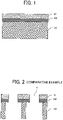
- FIG. 1 is a schematic cross-sectional view illustrating a configuration of the SOI substrate.
- the SOI substrate includes a first silicon layer 101, a second silicon layer 103, and a first silicon oxide film layer 102 sandwiched between the first silicon layer 101 and the second silicon layer 103.
- the SOI substrate has a structure in which a silicon oxide film layer having a high etching selectivity with respect to silicon is sandwiched between one silicon layer and the other silicon layer.
- a surface of a silicon substrate is oxidized, and another silicon substrate is attached to one surface of the silicon substrate to manufacture an SOI wafer. Accordingly, the variation in the thickness of the SOI wafer falls within a range of several hundreds nm.
- the SOI substrate is used in a two stage nozzle plate because the height of a small-diameter cylindrical portion serving as a nozzle hole of an inkjet head can be controlled with high accuracy.
- the SOI wafer is ground and thinned, and the front and back surface of the SOI wafer are patterned and etched. This manufacturing process uses the property of a silicon oxide film layer having a high etching selectivity with respect to silicon.
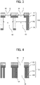
- FIG. 2 is a schematic cross-sectional view of a comparative two stage nozzle plate including the SOI substrate.
- the two stage nozzle plate according to the comparative example has a nozzle 4 and includes the SOI substrate including the first silicon layer 101, the second silicon layer 103, and the first silicon oxide film layer 102 sandwiched between the first silicon layer 101 and the second silicon layer 103.
- the wafer when the wafer is thinned in the above-described manufacturing process, the wafer is significantly warped toward the first silicon layer 101 due to the residual stress of the first silicon oxide film layer 102.
- the amount of warpage of the wafer varies in the plane thereof. Therefore, the visual inspection of the wafer may require a large number of focus points, thereby increasing the inspection time.
- FIG. 3 is a schematic cross-sectional view of the two stage nozzle plate including the SOI substrate according to the present embodiment.
- the two stage nozzle plate illustrated in FIG. 3 is different from the two stage nozzle plate in FIG. 2 in that a second silicon oxide film layer 104 is formed.
- a nozzle plate 110 includes the second silicon oxide film layer 104 on a surface of the second silicon layer 103 different from a surface of the second silicon layer 103 in contact with the first silicon oxide film layer 102.
- the surface different from the surface in contact with the first silicon oxide film layer 102 includes a surface opposite to the surface in contact with the first silicon oxide film layer 102.
- the nozzle plate 110 includes the second silicon oxide film layer 104 on the surface of the second silicon layer 103 opposite to the surface of the second silicon layer 103 in contact with the first silicon oxide film layer 102.
- the second silicon oxide film layer 104 Since the second silicon oxide film layer 104 is formed, the residual stress of the second silicon oxide film layer 104 can cancel the residual stress generated from the first silicon oxide film layer 102, thereby reducing the warpage of the wafer. As the warpage of the wafer is reduced, the amount of warpage of the wafer is prevented from varying in the plane thereof. Therefore, the focus points in the visual inspection does not increase, and thus the inspection time does not increase.
- the nozzle plate 110 has the nozzle 4 and includes the SOI substrate including the first silicon layer 101, the second silicon layer 103, and the first silicon oxide film layer 102 between the first silicon layer 101 and the second silicon layer 103.
- the nozzle plate 110 further includes the second silicon oxide film layer 104.
- the first silicon layer 101 is disposed on a side of a liquid discharge face of the liquid discharge head. In FIG. 3 , the upper side of the drawing corresponds to the liquid discharge face from which liquid is discharged.
- the thickness of the first silicon layer 101 is preferably about 15 ⁇ m or less.
- the total thickness of the first silicon layer 101 and the second silicon layer 103 is preferably 50 ⁇ m or more. As a result, the thickness of the first silicon layer 101 is smaller than the thickness of the second silicon layer 103.
- the SOI substrate in the nozzle plate 110 has a through hole 80 communicating with the nozzle 4.
- a diameter a of a portion of the through hole 80 penetrating the first silicon layer 101 is smaller than a diameter b of a portion of the through hole 80 penetrating the second silicon layer 103 (i.e., a ⁇ b).
- the nozzle plate 110 including the SOI substrate is referred to as the two stage nozzle plate.
- the nozzle plate 110 As a diameter of an outlet of the nozzle 4 is small, minute ink droplets can be discharged from the nozzle 4. As a result, the resolution of images is improved, and high-quality images can be formed.
- the diameter of the outlet of the nozzle 4 is small, and the nozzle 4 has the two stage shape to reduce the fluid resistance.
- the through hole 80 extends in a direction perpendicular to the substrate as illustrated in the present embodiment. In this case, liquid droplets can be discharged from the nozzle 4 with high accuracy.
- a depth of the small-diameter portion of the through hole 80 in other words, the total thickness of the first silicon layer 101 and the first silicon oxide film layer 102 is determined in consideration of discharge characteristics. Specifically, the total thickness of the first silicon layer 101 and the first silicon oxide film layer 102 is preferably smaller than the thickness of the second silicon layer 103. If the depth of the small-diameter portion of the through hole 80 is too large, the fluid resistance may increase and the discharge characteristics may be impaired. Therefore, by satisfying the above-described relation, the fluid resistance can be prevented from increasing, thereby improving the discharge characteristics.
- the total thickness of the first silicon layer 101 and the first silicon oxide film layer 102 is preferably 50 ⁇ m or more. In this case, the liquid level of the ink is likely to remain at the position corresponding to the first silicon layer 101 or the first silicon oxide film layer 102, thereby preventing the discharge characteristics from being impaired.
- the center of rigidity in the direction perpendicular to the substrate is within the second silicon layer 103.
- the second silicon oxide film layer 104 is closer to the center of rigidity than the first silicon oxide film layer 102. Therefore, the thickness of the first silicon oxide film layer 102 is preferably larger than the thickness of the second silicon oxide film layer 104 to balance the stresses of the first silicon oxide film layer 102 and the second silicon oxide film layer 104.
- the method of manufacturing the nozzle plate in the present embodiment can be appropriately selected and changed.
- Examples of the method of manufacturing the nozzle plate include a press method in which a metal plate is pressed to form a hole and a dry etching method in which a hole is etched on the silicon substrate.
- a dry etching method is preferable from the viewpoint of high controllability of the shape.
- the silicon layer of the SOI substrate illustrated in FIG. 1 is dry-etched.
- the silicon etching in the depth direction stops. Since the thickness of the SOI substrate can be controlled in the unit of several hundreds nm, the depth of the outlet small-diameter portion can be easily controlled.
- the comparative two stage nozzle plate there is widely known an example of manufacturing process in which, after the outlet small-diameter portion is formed, the opposite surface is ground to form a thin film. Then, the large-diameter portion is formed from the ground surface, and finally the silicon oxide film layer is removed.
- the second silicon oxide film layer 104 and an oxide film layer on the nozzle outlet side are formed by a thermal oxidation processed on the SOI substrate, for example.
- the oxide film layer on the nozzle outlet side is removed by etching.
- the nozzle 4 are formed by dry etching on the liquid discharge face of the SOI substrate.
- a polishing process is performed to adjust the thickness of the wafer to, for example, 50 ⁇ m, and finally the through hole 80 is formed by dry etching.
- the two stage nozzle plate including the SOI substrate according to the present embodiment is manufactured. Accordingly, the residual stress of the second silicon oxide film layer 104 can cancel the residual stress generated from the first silicon oxide film layer 102, thereby reducing the warpage of the wafer.
- FIG. 4 is a schematic cross-sectional view illustrating a nozzle plate 110 according to another embodiment.
- FIG. 4 is the cross-sectional view similar to FIG. 3 .
- the nozzle plate 110 includes the second silicon oxide film layer 104 on a surface of the second silicon layer 103 different from the surface of the second silicon layer 103 in contact with the first silicon oxide film layer 102. That is, a place where the second silicon oxide film layer 104 is formed is not limited to the place illustrated in FIG. 3 , and can be appropriately changed as long as the residual stress generated from the first silicon oxide film layer 102 can be canceled.
- the second silicon oxide film layer 104 may be formed on a surface of the second silicon layer 103 facing the through hole 80.
- the place where the second silicon oxide film layer 104 is formed can be appropriately changed. As illustrated in FIG. 4 , even if the second silicon oxide film layer 104 is formed only on the surface of the second silicon layer 103 facing the through hole 80, the residual stress generated from the first silicon oxide film layer 102 can be canceled, thereby obtaining the effect of the present disclosure. On the other hand, from the viewpoint of canceling the residual stress generated from the first silicon oxide film layer 102, it is more preferable that the second silicon oxide film layer 104 is formed on the surface of the second silicon layer 103 opposite to the surface in contact with the first silicon oxide film layer 102 and on the surface of the second silicon layer 103 facing the through hole 80.
- the residual stress generated from the first silicon oxide film layer 102 can be more surely canceled.
- the second silicon oxide film layer 104 is formed only on the surface of the second silicon layer 103 opposite to the surface in contact with the first silicon oxide film layer 102 as illustrated in FIG. 3 .
- FIG. 5 is a cross-sectional view illustrating an example of a liquid discharge head 100 in a direction (pressure-chamber longitudinal direction) perpendicular to a nozzle arrangement direction of the liquid discharge head 100 according to the embodiments.
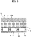
- FIG. 6 is a cross-sectional view of the liquid discharge head 100 in the nozzle arrangement direction along line A-A in FIG. 5 .
- the liquid discharge head 100 includes the nozzle plate 110, a channel plate 2 as an individual channel member, and a diaphragm 3 as a wall member that are laminated one on another and bonded to each other.
- the liquid discharge head 100 further includes a piezoelectric actuator 11 as an actuator to displace a vibration portion (vibration plate) 30 of the diaphragm 3 and a common channel member 20 also serving as a frame of the liquid discharge head 100.
- an individual liquid chamber is also referred to as a pressure chamber 6.
- the nozzle plate 110 includes a plurality of nozzles 4 to discharge liquid.
- FIGS. 5 and 6 and FIG. 8
- the nozzle plate 110 has the two stage shape as illustrated in FIGS. 3 and 4 .
- the channel plate 2 defines a plurality of pressure chambers 6 communicating with the plurality of nozzles 4 via the through holes 80, a plurality of individual supply channels 7 that are individual channels communicating with the respective pressure chambers 6, and a plurality of intermediate supply channels 8 that are liquid introduction portions each communicating with one or the plurality of individual supply channels 7 (e.g., one individual supply channel in the present embodiment).
- the diaphragm 3 includes a plurality of displaceable vibration portions (vibration plates) 30 that defines walls of the pressure chambers 6 of the channel plate 2.
- the diaphragm 3 has a two-layer structure (not limited), and is constructed of a first layer 3A forming a thin portion and a second layer 3B forming a thick portion from the channel plate 2 side.
- the displaceable vibration portion 30 is formed in a portion corresponding to the pressure chamber 6 in the first layer 3A that is the thin portion.
- a projection 30a is formed as the thick portion joined to the piezoelectric actuator 11 in the second layer 3B.
- the piezoelectric actuator 11 including an electromechanical transducer element serving as a driving device (an actuator device or a pressure generator device) to deform the vibration portion 30 of the diaphragm 3 is disposed on a side of the diaphragm 3 opposite a side facing the pressure chamber 6.
- a piezoelectric member bonded on a base 13 is grooved by half-cut dicing, to form a desired number of columnar piezoelectric elements 12 at predetermined intervals in a comb shape in the nozzle arrangement direction as illustrated in FIG. 6 .
- the piezoelectric element 12 is bonded to the projection 30a that is the thick portion in the vibration portion 30 of the diaphragm 3.
- the piezoelectric element 12 includes piezoelectric layers and internal electrodes alternately laminated on each other. Each internal electrode is led out to an end face and connected to an external electrode (end face electrode). The external electrode is connected to a flexible wiring 15.
- the common channel member 20 defines a common supply channel 10 communicating with the plurality of pressure chambers 6.
- the common supply channel 10 communicates with the intermediate supply channel 8 as the liquid introduction portion via an opening 9 provided in the diaphragm 3 and communicates with the individual supply channel 7 via the intermediate supply channel 8.
- the voltage to be applied to the piezoelectric element 12 is lowered from a reference potential (intermediate potential) so that the piezoelectric element 12 contracts to pull the vibration portion 30 of the diaphragm 3 to increase the volume of the pressure chamber 6.
- a reference potential intermediate potential
- the voltage to be applied to the piezoelectric element 12 is increased to expand the piezoelectric element 12 in the direction of lamination, and the vibration portion 30 of the diaphragm 3 is deformed in a direction toward the nozzle 4 to reduce the volume of the pressure chamber 6.
- the liquid in the pressure chamber 6 is pressurized and discharged from the nozzle 4.
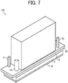
- FIG. 7 is a perspective view illustrating another example of the liquid discharge head 100 according to the embodiments of the present disclosure.
- FIG. 8 is a cross-sectional view illustrating the example of the liquid discharge head 100 in FIG. 7 according to the embodiments of the present disclosure in a direction (pressure-chamber longitudinal direction) perpendicular to the nozzle arrangement direction of the liquid discharge head 100.
- the liquid discharge head 100 according to the present embodiment is a circulation type liquid discharge head, and includes the nozzle plate 110, the channel plate 2, and the diaphragm 3 as a wall member, which are laminated one on another and bonded to each other.
- the liquid discharge head 100 further includes the piezoelectric actuator 11 to displace the vibration portion (vibration plate) 30 of the diaphragm 3 and the common channel member 20 that also serves as the frame of the liquid discharge head 100.
- the channel plate 2 defines the plurality of pressure chambers 6 communicating with the plurality of nozzles 4 via nozzle communication passages 5, the individual supply channels 7 also serving as a plurality of fluid restrictors communicating with the plurality of pressure chambers 6, and the intermediate supply channels 8 serving as one or a plurality of liquid introduction portions communicating with two or more individual supply channels 7.
- the individual supply channel 7 includes two channel portions, i.e., a first channel portion 7A and a second channel portion 7B having a higher fluid resistance than the pressure chamber 6, and a third channel portion 7C disposed between the first channel portion 7A and the second channel portion 7B and having a lower fluid resistance than each of the first channel portion 7A and the second channel portion 7B.
- the channel plate 2 has a configuration in which a plurality of plate members 2A to 2E are laminated one on another.
- the configuration of the channel plate is not limited thereto.
- the channel plate 2 further defines a plurality of individual collection channels 57 and a plurality of intermediate collection channels 58.
- the individual collection channels 57 are formed along the surface direction of the channel plate 2 that respectively communicate with the plurality of pressure chambers 6 via the nozzle communication passages 5.
- the intermediate collection channels 58 serves as one or a plurality of liquid lead-out portions that communicates with two or more individual collection channels 57.
- the individual collection channel 57 includes two channel portions, i.e., a first channel portion 57A and a second channel portion 57B having a higher fluid resistance than the pressure chamber 6, and a third channel portion 57C disposed between the first channel portion 57A and the second channel portion 57B and having a lower fluid resistance than each of the first channel portion 57A and the second channel portion 57B.
- the individual collection channel 57 further includes a channel portion 57D downstream from the second channel portion 57B in the direction of circulation of the liquid.
- the channel portion 57D has the same channel width as the third channel portion 57C.
- the common channel member 20 defines the common supply channel 10 and a common collection channel 50.
- the common supply channel 10 includes a channel portion 10A that is disposed side by side with the common collection channel 50 in the nozzle arrangement direction and a channel portion 10B that is not disposed side by side with the common collection channel 50.
- the common supply channel 10 communicates with the intermediate supply channel 8 as the liquid introduction portion via the opening 9 provided in the diaphragm 3 and communicates with the individual supply channel 7 via the intermediate supply channel 8.
- the common collection channel 50 communicates with the intermediate collection channel 58 as the liquid lead-out portion via an opening 59 provided in the diaphragm 3 and communicates with the individual collection channel 57 via the intermediate collection channel 58.
- the common supply channel 10 communicates with a supply port 71.
- the common collection channel 50 communicates with a collection port 72.
- the other configurations such as layer configuration of the diaphragm 3 and the configuration of the piezoelectric actuator 11 are the same as the configurations in the above-described example.
- the piezoelectric element 12 is expanded in the direction of lamination, and the vibration portion 30 of the diaphragm 3 is deformed in the direction toward the nozzle 4 to reduce the volume of the pressure chamber 6.
- liquid in the pressure chamber 6 is pressurized and discharged from the nozzle 4.
- the liquid not discharged from the nozzle 4 passes the nozzle 4, is collected from the individual collection channel 57 to the common collection channel 50, and is supplied again to the common supply channel 10 through an external circulation passage from the common collection channel 50.
- the liquid circulates from the common supply channel 10 to the common collection channel 50 through the pressure chamber 6 and is supplied again to the common supply channel 10 through the external circulation passage.
- the pressure fluctuation accompanying liquid discharge can be attenuated with a simple configuration, thus restraining propagation of the pressure fluctuation to the common supply channel 10 and the common collection channel 50.
- FIG. 9 is a schematic view of the liquid discharge apparatus.
- FIG. 10 is a plan view of a head unit of the liquid discharge apparatus in FIG. 9 .
- a printing apparatus 500 serving as the liquid discharge apparatus includes, e.g., a feeder 501, a guide conveyor 503, a printer 505, a drier 507, and a carrier 509.
- the feeder 501 feeds a continuous medium 510 inward.
- the guide conveyor 503 guides and conveys the continuous medium 510 such as a continuous sheet of paper or a sheet medium fed inward from the feeder 501.
- the printer 505 performs printing by discharging liquid onto the continuous medium 510 to form an image.
- the drier 507 dries the continuous medium 510 with the image formed.
- the carrier 509 feeds the dried continuous medium 510 outward.
- the continuous medium 510 is fed from a winding roller 511 of the feeder 501, guided and conveyed with rollers of the feeder 501, the guide conveyor 503, the drier 507, and the carrier 509, and wound around a take-up roller 591 of the carrier 509.
- the continuous medium 510 is conveyed on a conveyance guide so as to face a head unit 550 and a head unit 555.
- An image is formed with liquid discharged from the head unit 550, and post-treatment is performed with treatment liquid discharged from the head unit 555.
- the head unit 550 includes, for example, full-line head arrays 551A, 551B, 551C, and 551D for four colors from the upstream side in a conveyance direction of the continuous medium 510 indicated by arrow CD in FIG. 10 .
- the full-line head arrays 551A, 551B, 551C, and 551D are simply referred to as the "head array 551" when colors are not distinguished.
- Each of the head arrays 551 is a liquid discharger to discharge liquid of black (K), cyan (C), magenta (M), or yellow (Y) onto the continuous medium 510 conveyed along the conveyance direction of the continuous medium 510.
- K black
- C cyan
- M magenta
- Y yellow
- the number and types of colors are not limited to the above-described four colors of K, C, M, and Y and may be any other suitable number and types.
- liquid discharge heads 100 according to the present embodiment are disposed in a staggered arrangement on a base 552 to form the head array 551.
- the configuration of the head array 551 is not limited to such a configuration.
- the liquid discharge head 100 is also simply referred to as the "head 100."
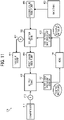
- FIG. 11 illustrates an example of a liquid circulation device 600 employed in the printing apparatus 500 according to the present embodiment.
- FIG. 11 is a block diagram of the liquid circulation device 600.
- a plurality of supply-side flow paths and a plurality of collection-side flow paths are respectively connected via manifolds or the like to the supply sides and collection sides of the plurality of heads 100.
- the liquid circulation device 600 includes a supply tank 601, a collection tank 602, a main tank 603, a first liquid feed pump 604, a second liquid feed pump 605, a compressor 611, a regulator 612, a vacuum pump 621, a regulator 622, a supply-side pressure sensor 631, a collection-side pressure sensor 632, and the like.
- the compressor 611 and the vacuum pump 621 together generate a difference between the pressure in the supply tank 601 and the pressure in the collection tank 602.
- the supply-side pressure sensor 631 is disposed between the supply tank 601 and the head 100 and coupled to the supply-side flow path connected to the supply port 71 (see FIG. 7 ) of the head 100.
- the collection-side pressure sensor 632 is disposed between the head 100 and the collection tank 602 and coupled to the collection-side flow path connected to the collection port 72 (see FIG. 7 ) of the head 100.
- One end of the collection tank 602 is coupled to the supply tank 601 via the first liquid feed pump 604, and another end of the collection tank 602 is coupled to the main tank 603 via the second liquid feed pump 605. Accordingly, liquid flows from the supply tank 601 into the head 100 through the supply port 71. Then, the liquid is collected from the collection port 72 to the collection tank 602 and is sent from the collection tank 602 to the supply tank 601 by the first liquid feed pump 604, thereby forming a circulation path through which the liquid circulates.
- the compressor 611 is coupled to the supply tank 601 and is controlled so that a predetermined positive pressure is detected by the supply-side pressure sensor 631.
- the vacuum pump 621 is coupled to the collection tank 602 and is controlled so that a predetermined negative pressure is detected by the collection-side pressure sensor 632.
- the second liquid feed pump 605 appropriately replenishes liquid from the main tank 603 to the collection tank 602.
- the timing of liquid replenishment from the main tank 603 to the collection tank 602 can be controlled based on, for example, the detection result of a liquid level sensor provided in the collection tank 602. In such a case, for example, the liquid replenishment may be performed when the liquid level of the liquid in the collection tank 602 falls below a predetermined height.
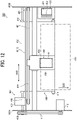
- FIG. 12 is a plan view of a part of the printing apparatus 500.
- FIG. 13 is a side view of the part of the printing apparatus 500 in FIG. 12 .
- the printing apparatus 500 is a serial type apparatus, and a main-scanning moving mechanism 493 reciprocally moves a carriage 403 in a main scanning direction indicated by arrow MSD in FIG. 12 .
- the main-scanning moving mechanism 493 includes, e.g., a guide 401, a main-scanning motor 405, and a timing belt 408.
- the guide 401 is bridged between left and right side plates 491A and 491B to moveably hold the carriage 403.
- the main-scanning motor 405 reciprocates the carriage 403 in the main scanning direction via the timing belt 408 looped around a drive pulley 406 and a driven pulley 407.
- the carriage 403 mounts a liquid discharge device 440 including the liquid discharge head 100 according to the present embodiment and a head tank 441 as a single integrated unit.
- the head tank 441 stores liquid to be supplied to the liquid discharge heard 100.
- the liquid discharge head 100 of the liquid discharge device 440 discharges color liquid of, for example, yellow (Y), cyan (C), magenta (M), or black (K).
- the liquid discharge head 100 includes a nozzle array including the plurality of nozzles 4 arrayed in row in the sub-scanning direction indicated by arrow SSD perpendicular to the main scanning direction indicated by arrow MSD in FIG. 12 .
- the liquid discharge head 100 is mounted to the carriage 403 so that liquid is discharged downward from the nozzles 4.
- the liquid discharge head 100 is coupled to the liquid circulation device 600 described above so that liquid of a required color is circulated and supplied.
- the printing apparatus 500 includes a conveyance mechanism 495 to convey a sheet 410.
- the conveyance mechanism 495 includes a conveyance belt 412 as a conveyor and a sub-scanning motor 416 to drive the conveyance belt 412.
- the conveyance belt 412 attracts the sheet 410 and conveys the sheet 410 at a position facing the liquid discharge head 100.
- the conveyance belt 412 is an endless belt stretched between a conveyance roller 413 and a tension roller 414.
- the sheet 410 can be attracted to the conveyance belt 412 by electrostatic attraction, air suction, or the like.
- the conveyance belt 412 circumferentially moves in the sub-scanning direction as the conveyance roller 413 is rotationally driven by the sub-scanning motor 416 via a timing belt 417 and a timing pulley 418.
- a maintenance mechanism 420 that maintains and recovers the liquid discharge head 100 is disposed lateral to the conveyance belt 412.
- the maintenance mechanism 420 includes, for example, a cap 421 to cap a nozzle face (i.e., a face on which nozzles are formed, that is, the liquid discharge face) of the liquid discharge head 100 and a wiper 422 to wipe the nozzle face.
- the main-scanning moving mechanism 493, the maintenance mechanism 420, and the conveyance mechanism 495 are mounted onto a housing including the side plates 491A and 491B and a back plate 491C.
- the sheet 410 is fed and attracted onto the conveyance belt 412 and conveyed in the sub-scanning direction by the circumferential movement of the conveyance belt 412.
- the liquid discharge head 100 is driven in response to image signals while the carriage 403 moves in the main scanning direction to discharge liquid to the sheet 410 not in motion, thus forming an image on the sheet 410.
- FIG. 14 is a plan view of the liquid discharge device 440.
- the liquid discharge device 440 includes a housing, the main-scanning moving mechanism 493, the carriage 403, and the liquid discharge head 100 among components of the liquid discharge apparatus described above.
- the side plates 491A and 491B, and the back plate 491C constitute the housing.
- the maintenance mechanism 420 described above may be mounted on, for example, the side plate 491B.
- FIG. 15 is a front view of the liquid discharge device 440.
- the liquid discharge device 440 includes the liquid discharge head 100 to which a channel component 444 is attached, and a tube 456 connected to the channel component 444.
- the tube 456 serves as a supply mechanism to supply liquid to the liquid discharge head 100.
- the channel component 444 is disposed inside a cover 442.
- the liquid discharge device 440 may include the head tank 441 instead of the channel component 444.
- a connector 443 for electrically connecting to the liquid discharge head 100 is provided on an upper portion of the channel component 444.
- the liquid to be discharged is not limited to a particular liquid as long as the liquid has a viscosity or surface tension to be discharged from a head (liquid discharge head).
- the viscosity of the liquid is not greater than 30 mPa ⁇ s under ordinary temperature and ordinary pressure or by heating or cooling.
- the liquid include a solution, a suspension, or an emulsion including, for example, a solvent, such as water or an organic solvent, a colorant, such as dye or pigment, a functional material, such as a polymerizable compound, a resin, a surfactant, a biocompatible material, such as DNA, amino acid, protein, or calcium, and an edible material, such as a natural colorant.
- Such a solution, a suspension, or an emulsion can be used for, e.g., inkjet ink; surface treatment liquid; a liquid for forming an electronic element component, a light-emitting element component, or an electronic circuit resist pattern; or a material solution for three-dimensional fabrication.
- Examples of an energy source for generating energy to discharge liquid include a piezoelectric actuator (a laminated piezoelectric element or a thin-film piezoelectric element), a thermal actuator that employs a thermoelectric conversion element, such as a thermal resistor, and an electrostatic actuator including a diaphragm and a counter electrode.
- a piezoelectric actuator a laminated piezoelectric element or a thin-film piezoelectric element
- a thermal actuator that employs a thermoelectric conversion element, such as a thermal resistor
- an electrostatic actuator including a diaphragm and a counter electrode.
- liquid discharge device is an assembly of parts relating to liquid discharge.
- the term “liquid discharge device” represents a structure including the liquid discharge head and a functional part(s) or unit(s) combined with the liquid discharge head as a single unit.
- the “liquid discharge device” includes a combination of the liquid discharge head with at least one of a head tank, a carriage, a supply mechanism, a maintenance mechanism, a main-scanning moving mechanism, and a liquid circulation device.
- the terms “integrated” and “combined” mean attaching the liquid discharge head and the functional components (or mechanisms) to each other by fastening, screwing, binding, or engaging and movably holding one of the liquid discharge head and the functional components relative to the other.
- the liquid discharge head, the functional components, and the mechanisms may also be detachably attached to one another.
- the liquid discharge head and the head tank are integrated as the liquid discharge unit.
- the liquid discharge head and the head tank coupled (connected) to each other via a tube or the like may form the liquid discharge unit as a single unit.
- a unit including a filter may further be added to a portion between the head tank and the liquid discharge head.
- the liquid discharge unit may include the liquid discharge head integrated with the carriage as a single unit.
- the liquid discharge unit is a unit in which the liquid discharge head and the main-scanning moving mechanism are combined into a single unit.
- the liquid discharge head is movably held by a guide that is a part of the main-scanning moving mechanism.
- the liquid discharge unit may include the liquid discharge head, the carriage, and the main-scanning moving mechanism that are integrated as a single unit.
- a cap that is a part of the maintenance mechanism may be secured to the carriage mounting the liquid discharge head so that the liquid discharge head, the carriage, and the maintenance mechanism are combined into a single unit to form the liquid discharge unit.
- the liquid discharge unit includes tubes connected to the liquid discharge head mounting the head tank or the channel component so that the liquid discharge head and the supply mechanism are integrated as a single unit. Through the tubes, the liquid in a liquid storage source is supplied to the liquid discharge head.
- the main-scanning moving mechanism may be a guide only.
- the supply mechanism may be a tube(s) only or a loading device only.
- liquid discharge apparatus also represents an apparatus including the liquid discharge head or the liquid discharge device to drive the liquid discharge head to discharge liquid.
- the liquid discharge apparatus may be, for example, an apparatus capable of discharging liquid to a material onto which liquid can adhere or an apparatus to discharge liquid toward gas or into liquid.
- the "liquid discharge apparatus” may include devices relating to feeding, conveyance, and ejection of the material to which the liquid can adhere and also include a pretreatment device and a post-processing device.
- the “liquid discharge apparatus” may be, for example, an image forming apparatus to form an image on a sheet by discharging ink, or a three-dimensional apparatus to discharge a fabrication liquid to a powder layer in which powder material is formed in layers, so as to form a three-dimensional object.
- the “liquid discharge apparatus” is not limited to an apparatus that discharges liquid to visualize meaningful images such as letters or figures.
- the liquid discharge apparatus may be an apparatus that forms meaningless images such as meaningless patterns or an apparatus that fabricates three-dimensional images.
- material to which liquid can adhere denotes, for example, a material to which liquid can adhere at least temporarily, a material to which liquid can attach and firmly adhere, or a material to which liquid can adhere and into which the liquid permeates.
- Specific examples of the "material to which liquid can adhere” include, but are not limited to, a recording medium such as a paper sheet, recording paper, a recording sheet of paper, a film, or cloth, an electronic component such as an electronic substrate or a piezoelectric element, and a medium such as layered powder, an organ model, or a testing cell.
- the "material to which liquid is adhere” includes any material to which liquid can adhere, unless particularly limited.
- Examples of the "material to which liquid can adhere” include any materials to which liquid can adhere even temporarily, such as paper, thread, fiber, fabric, leather, metal, plastic, glass, wood, and ceramic.
- liquid discharge apparatus may be an apparatus to relatively move the liquid discharge head and the material to which liquid can adhere.
- the liquid discharge apparatus is not limited to such an apparatus.
- Examples of the liquid discharge apparatus include a serial type apparatus which moves the liquid discharge head, and a line type apparatus which does not move the liquid discharge head.
- Examples of the liquid discharge apparatus further include: a treatment liquid applying apparatus that discharges a treatment liquid onto a paper sheet to apply the treatment liquid to the surface of the paper sheet, for reforming the surface of the paper sheet; and an injection granulation apparatus that injects a composition liquid, in which a raw material is dispersed in a solution, through a nozzle to granulate fine particle of the raw material.
- a treatment liquid applying apparatus that discharges a treatment liquid onto a paper sheet to apply the treatment liquid to the surface of the paper sheet, for reforming the surface of the paper sheet
- an injection granulation apparatus that injects a composition liquid, in which a raw material is dispersed in a solution, through a nozzle to granulate fine particle of the raw material.
- image formation means “image formation,” “recording,” “printing,” “image printing,” and “fabricating” used in the embodiments of the present disclosure may be used synonymously with each other.
Landscapes
- Engineering & Computer Science (AREA)
- Manufacturing & Machinery (AREA)
- Particle Formation And Scattering Control In Inkjet Printers (AREA)
- Ink Jet (AREA)
Abstract
Description
- Aspects of the present disclosure relate to a liquid discharge head, a liquid discharge device, and a liquid discharge apparatus.
- Inkjet recording apparatuses have many advantages, such as extremely noiseless operation, high-speed printing, a high degree of flexibility in ink, i.e., liquid for image formation, and availability of low-cost plain paper. Accordingly, the inkjet recording apparatuses are widely used as image recording apparatuses or image forming apparatuses, such as printers, facsimile machines, and copiers.
- The basic function of an inkjet head used in the inkjet recording apparatus is to discharge ink droplets perpendicularly to the surface of a sheet. If the inkjet head discharges ink droplets obliquely, a streak may appear in an image formed on the sheet, thereby impairing the quality of the image. To avoid such a situation, the key configuration of the inkjet head includes the shape of a nozzle from which ink is discharged.
- The nozzle is formed on a nozzle plate. There is known a technique for manufacturing a two stage nozzle plate using silicon (Si) etching and silicon dioxide (SiO2) etching on a silicon on insulator (SOI) substrate. The SOI substrate has a structure in which a silicon oxide film layer is sandwiched between one silicon layer and the other silicon layer, and is generally used for manufacturing a large scale integration (LSI). When such a two stage nozzle plate is manufactured, for example, an SOI wafer is ground and thinned, and the front and back surface of the SOI wafer are patterned and etched. This manufacturing process uses the property of a silicon oxide film layer having a high etching selectivity with respect to silicon.
- However, such a two stage nozzle plate including the SOI substrate is warped in a direction toward one of the silicon layers due to residual stress of the silicon oxide film layer. When the wafer is thinned in the above-described manufacturing process, the warpage of the wafer becomes significant due to the residual stress of the silicon oxide film layer, and the amount of warpage of the wafer varies in the plane thereof. Therefore, the visual inspection of the wafer may require a large number of focus points, thereby increasing the inspection time.
-
Japanese Unexamined Patent Application Publication No. 2010-142991 Japanese Unexamined Patent Application Publication No. 2010-142991 - In
Japanese Unexamined Patent Application Publication No. 2010-142991 Japanese Unexamined Patent Application Publication No. 2010-142991 - To solve such a situation described above, an object of the present disclosure is to provide a liquid discharge head that can prevent a nozzle plate, the nozzle plate including an SOI substrate in particular, from being warped.
- Embodiments of the present disclosure describe an improved liquid discharge head that includes a nozzle plate, an individual liquid chamber, and an actuator. The nozzle plate has a nozzle on a liquid discharge face and a through hole communicating with the nozzle and penetrating the nozzle plate. The nozzle plate includes a substrate including a first silicon layer on a side of the liquid discharge face, a second silicon layer, a first silicon oxide film layer between the first silicon layer and the second silicon layer, and a second silicon oxide film layer on a surface of the second silicon layer different from a surface of the second silicon layer in contact with the first silicon oxide film layer. The individual liquid chamber communicates with the nozzle via the through hole. The actuator pressurizes a liquid in the individual liquid chamber to discharge the liquid from the nozzle. A thickness of the first silicon layer is smaller than a thickness of the second silicon layer. A portion of the through hole penetrating the first silicon layer has a smaller diameter than a portion of the through hole penetrating the second silicon layer.
- As a result, according to the present disclosure, the nozzle plate, the nozzle plate including the SOI substrate in particular, can be prevented from being warped.
- A more complete appreciation of the disclosure and many of the attendant advantages thereof will be readily obtained as the same becomes better understood by reference to the following detailed description when considered in connection with the accompanying drawings, wherein:
-
FIG. 1 is a schematic cross-sectional view illustrating a configuration of a silicon on insulator) SOI substrate; -
FIG. 2 is a schematic cross-sectional view of a nozzle plate of a liquid discharge head according to a comparative example; -
FIG. 3 is a schematic cross-sectional view of a nozzle plate of a liquid discharge head according to an embodiment of the present disclosure; -
FIG. 4 is a schematic cross-sectional view of a nozzle plate of a liquid discharge head according to another embodiment of the present disclosure; -
FIG. 5 is a schematic cross-sectional view illustrating an example of the liquid discharge head according to embodiments of the present disclosure; -
FIG. 6 is another schematic cross-sectional view illustrating the example of the liquid discharge head inFIG. 5 according to embodiments of the present disclosure; -
FIG. 7 is a schematic perspective view illustrating another example of the liquid discharge head according to embodiments of the present disclosure; -
FIG. 8 is a schematic cross-sectional view illustrating the example of the liquid discharge head inFIG. 7 according to embodiments of the present disclosure; -
FIG. 9 is a schematic view illustrating an example of a liquid discharge apparatus according to embodiments of the present disclosure; -
FIG. 10 is a schematic plan view illustrating an example of a head unit of the liquid discharge apparatus inFIG. 9 ; -
FIG. 11 is a block diagram of a liquid circulation device according to embodiments of the present disclosure; -
FIG. 12 is a schematic view illustrating another example of the liquid discharge apparatus according to embodiments of the present disclosure; -
FIG. 13 is a schematic view of the liquid discharge apparatus inFIG. 12 according to embodiments of the present disclosure; -
FIG. 14 is a schematic view illustrating an example of a liquid discharge device according to embodiments of the present disclosure; and -
FIG. 15 is a schematic view illustrating another example of the liquid discharge device according to embodiments of the present disclosure. - The accompanying drawings are intended to depict embodiments of the present disclosure and should not be interpreted to limit the scope thereof. The accompanying drawings are not to be considered as drawn to scale unless explicitly noted. In addition, identical or similar reference numerals designate identical or similar components throughout the several views.
- In describing embodiments illustrated in the drawings, specific terminology is employed for the sake of clarity. However, the disclosure of this patent specification is not intended to be limited to the specific terminology so selected, and it is to be understood that each specific element includes all technical equivalents that have the same function, operate in a similar manner, and achieve a similar result.
- As used herein, the singular forms "a," "an," and "the" are intended to include the plural forms as well, unless the context clearly indicates otherwise.
- Hereinafter, a liquid discharge head, a liquid discharge device, and a liquid discharge apparatus according to embodiments of the present disclosure is described with reference to the drawings. It is to be noted that the following embodiments are not limiting the present disclosure and any deletion, addition, modification, change, etc. can be made within a scope in which person skilled in the art can conceive including other embodiments, and any of which is included within the scope of the present disclosure as long as the effect and feature of the present disclosure are demonstrated.
- According to embodiments of the present disclosure, a liquid discharge head includes a nozzle plate, an individual liquid chamber, and an actuator. The nozzle plate has a nozzle on a liquid discharge face and a through hole communicating with the nozzle and penetrating the nozzle plate. The nozzle plate includes a substrate including a first silicon oxide film layer, a first silicon layer on a side of the liquid discharge face, and a second silicon layer. The second silicon layer includes a second silicon oxide film layer on a surface of the second silicon layer different from a surface of the second silicon layer in contact with the first silicon oxide film layer. The first silicon layer and the second silicon layer sandwich the first silicon oxide film layer. The individual liquid chamber communicates with the nozzle via the through hole. The actuator pressurizes a liquid in the individual liquid chamber to discharge the liquid from the nozzle. A thickness of the first silicon layer is smaller than a thickness of the second silicon layer. A portion of the through hole penetrating the first silicon layer has a smaller diameter than a portion of the through hole penetrating the second silicon layer.
- A nozzle plate according to the present embodiment includes a silicon on insulator (SOI) substrate.
FIG. 1 is a schematic cross-sectional view illustrating a configuration of the SOI substrate. The SOI substrate includes afirst silicon layer 101, asecond silicon layer 103, and a first siliconoxide film layer 102 sandwiched between thefirst silicon layer 101 and thesecond silicon layer 103. The SOI substrate has a structure in which a silicon oxide film layer having a high etching selectivity with respect to silicon is sandwiched between one silicon layer and the other silicon layer. - A surface of a silicon substrate is oxidized, and another silicon substrate is attached to one surface of the silicon substrate to manufacture an SOI wafer. Accordingly, the variation in the thickness of the SOI wafer falls within a range of several hundreds nm. In view of such a point, the SOI substrate is used in a two stage nozzle plate because the height of a small-diameter cylindrical portion serving as a nozzle hole of an inkjet head can be controlled with high accuracy. When the two stage nozzle plate including the SOI substrate is manufactured, for example, the SOI wafer is ground and thinned, and the front and back surface of the SOI wafer are patterned and etched. This manufacturing process uses the property of a silicon oxide film layer having a high etching selectivity with respect to silicon.
-
FIG. 2 is a schematic cross-sectional view of a comparative two stage nozzle plate including the SOI substrate. The two stage nozzle plate according to the comparative example has anozzle 4 and includes the SOI substrate including thefirst silicon layer 101, thesecond silicon layer 103, and the first siliconoxide film layer 102 sandwiched between thefirst silicon layer 101 and thesecond silicon layer 103. - In a comparative technique, when the wafer is thinned in the above-described manufacturing process, the wafer is significantly warped toward the
first silicon layer 101 due to the residual stress of the first siliconoxide film layer 102. When the wafer is warped, the amount of warpage of the wafer varies in the plane thereof. Therefore, the visual inspection of the wafer may require a large number of focus points, thereby increasing the inspection time. -
FIG. 3 is a schematic cross-sectional view of the two stage nozzle plate including the SOI substrate according to the present embodiment. The two stage nozzle plate illustrated inFIG. 3 is different from the two stage nozzle plate inFIG. 2 in that a second siliconoxide film layer 104 is formed. In the present embodiment, anozzle plate 110 includes the second siliconoxide film layer 104 on a surface of thesecond silicon layer 103 different from a surface of thesecond silicon layer 103 in contact with the first siliconoxide film layer 102. The surface different from the surface in contact with the first siliconoxide film layer 102 includes a surface opposite to the surface in contact with the first siliconoxide film layer 102. In the present embodiment, thenozzle plate 110 includes the second siliconoxide film layer 104 on the surface of thesecond silicon layer 103 opposite to the surface of thesecond silicon layer 103 in contact with the first siliconoxide film layer 102. - Since the second silicon
oxide film layer 104 is formed, the residual stress of the second siliconoxide film layer 104 can cancel the residual stress generated from the first siliconoxide film layer 102, thereby reducing the warpage of the wafer. As the warpage of the wafer is reduced, the amount of warpage of the wafer is prevented from varying in the plane thereof. Therefore, the focus points in the visual inspection does not increase, and thus the inspection time does not increase. - Next, details of the present embodiment are described with reference to
FIG. 3 . Thenozzle plate 110 according to the present embodiment has thenozzle 4 and includes the SOI substrate including thefirst silicon layer 101, thesecond silicon layer 103, and the first siliconoxide film layer 102 between thefirst silicon layer 101 and thesecond silicon layer 103. Thenozzle plate 110 further includes the second siliconoxide film layer 104. In thenozzle plate 110, thefirst silicon layer 101 is disposed on a side of a liquid discharge face of the liquid discharge head. InFIG. 3 , the upper side of the drawing corresponds to the liquid discharge face from which liquid is discharged. - To prevent the liquid from being obliquely discharged, the thickness of the
first silicon layer 101 is preferably about 15 µm or less. To secure rigidity of the wafer, the total thickness of thefirst silicon layer 101 and thesecond silicon layer 103 is preferably 50 µm or more. As a result, the thickness of thefirst silicon layer 101 is smaller than the thickness of thesecond silicon layer 103. - The SOI substrate in the
nozzle plate 110 has a throughhole 80 communicating with thenozzle 4. In the present embodiment, as illustrated inFIG. 3 , a diameter a of a portion of the throughhole 80 penetrating thefirst silicon layer 101 is smaller than a diameter b of a portion of the throughhole 80 penetrating the second silicon layer 103 (i.e., a < b). When this relation of a < b is satisfied, thenozzle plate 110 including the SOI substrate is referred to as the two stage nozzle plate. - In the
nozzle plate 110, as a diameter of an outlet of thenozzle 4 is small, minute ink droplets can be discharged from thenozzle 4. As a result, the resolution of images is improved, and high-quality images can be formed. On the other hand, as a volume of thenozzle 4 or the throughhole 80 communicating with thenozzle 4 is small, the fluid resistance increases, and the flexibility in discharge control is impaired. Therefore, preferably, the diameter of the outlet of thenozzle 4 is small, and thenozzle 4 has the two stage shape to reduce the fluid resistance. In addition, preferably, the throughhole 80 extends in a direction perpendicular to the substrate as illustrated in the present embodiment. In this case, liquid droplets can be discharged from thenozzle 4 with high accuracy. - In the two stage nozzle plate, preferably, a depth of the small-diameter portion of the through
hole 80, in other words, the total thickness of thefirst silicon layer 101 and the first siliconoxide film layer 102 is determined in consideration of discharge characteristics. Specifically, the total thickness of thefirst silicon layer 101 and the first siliconoxide film layer 102 is preferably smaller than the thickness of thesecond silicon layer 103. If the depth of the small-diameter portion of the throughhole 80 is too large, the fluid resistance may increase and the discharge characteristics may be impaired. Therefore, by satisfying the above-described relation, the fluid resistance can be prevented from increasing, thereby improving the discharge characteristics. - In addition, when ink is discharged, a liquid level of the ink is required to remain in a nozzle outlet cylinder (i.e., the small-diameter portion of the through hole 80). If the liquid level reaches a large-diameter portion of the through
hole 80, the discharge characteristics may be impaired. Therefore, the total thickness of thefirst silicon layer 101 and the first siliconoxide film layer 102 is preferably 50 µm or more. In this case, the liquid level of the ink is likely to remain at the position corresponding to thefirst silicon layer 101 or the first siliconoxide film layer 102, thereby preventing the discharge characteristics from being impaired. - In the present embodiment, the center of rigidity in the direction perpendicular to the substrate is within the
second silicon layer 103. The second siliconoxide film layer 104 is closer to the center of rigidity than the first siliconoxide film layer 102. Therefore, the thickness of the first siliconoxide film layer 102 is preferably larger than the thickness of the second siliconoxide film layer 104 to balance the stresses of the first siliconoxide film layer 102 and the second siliconoxide film layer 104. - The method of manufacturing the nozzle plate in the present embodiment can be appropriately selected and changed. Examples of the method of manufacturing the nozzle plate include a press method in which a metal plate is pressed to form a hole and a dry etching method in which a hole is etched on the silicon substrate. A dry etching method is preferable from the viewpoint of high controllability of the shape.
- For example, the silicon layer of the SOI substrate illustrated in
FIG. 1 is dry-etched. When the silicon of the SOI substrate is etched up to the silicon oxide film layer, the silicon etching in the depth direction stops. Since the thickness of the SOI substrate can be controlled in the unit of several hundreds nm, the depth of the outlet small-diameter portion can be easily controlled. - In the comparative two stage nozzle plate, there is widely known an example of manufacturing process in which, after the outlet small-diameter portion is formed, the opposite surface is ground to form a thin film. Then, the large-diameter portion is formed from the ground surface, and finally the silicon oxide film layer is removed.
- On the other hand, in the present embodiment, the second silicon
oxide film layer 104 and an oxide film layer on the nozzle outlet side are formed by a thermal oxidation processed on the SOI substrate, for example. After that, the oxide film layer on the nozzle outlet side is removed by etching. Next, thenozzle 4 are formed by dry etching on the liquid discharge face of the SOI substrate. Then, a polishing process is performed to adjust the thickness of the wafer to, for example, 50 µm, and finally the throughhole 80 is formed by dry etching. Thus, the two stage nozzle plate including the SOI substrate according to the present embodiment is manufactured. Accordingly, the residual stress of the second siliconoxide film layer 104 can cancel the residual stress generated from the first siliconoxide film layer 102, thereby reducing the warpage of the wafer. - Next, another embodiment is described.
FIG. 4 is a schematic cross-sectional view illustrating anozzle plate 110 according to another embodiment.FIG. 4 is the cross-sectional view similar toFIG. 3 . In the present embodiment, thenozzle plate 110 includes the second siliconoxide film layer 104 on a surface of thesecond silicon layer 103 different from the surface of thesecond silicon layer 103 in contact with the first siliconoxide film layer 102. That is, a place where the second siliconoxide film layer 104 is formed is not limited to the place illustrated inFIG. 3 , and can be appropriately changed as long as the residual stress generated from the first siliconoxide film layer 102 can be canceled. As illustrated in the present embodiment, the second siliconoxide film layer 104 may be formed on a surface of thesecond silicon layer 103 facing the throughhole 80. - As described above, the place where the second silicon
oxide film layer 104 is formed can be appropriately changed. As illustrated inFIG. 4 , even if the second siliconoxide film layer 104 is formed only on the surface of thesecond silicon layer 103 facing the throughhole 80, the residual stress generated from the first siliconoxide film layer 102 can be canceled, thereby obtaining the effect of the present disclosure. On the other hand, from the viewpoint of canceling the residual stress generated from the first siliconoxide film layer 102, it is more preferable that the second siliconoxide film layer 104 is formed on the surface of thesecond silicon layer 103 opposite to the surface in contact with the first siliconoxide film layer 102 and on the surface of thesecond silicon layer 103 facing the throughhole 80. In this case, the residual stress generated from the first siliconoxide film layer 102 can be more surely canceled. In consideration of the manufacturing process, it is more preferable that the second siliconoxide film layer 104 is formed only on the surface of thesecond silicon layer 103 opposite to the surface in contact with the first siliconoxide film layer 102 as illustrated inFIG. 3 . - A basic configuration according to the embodiments of the present disclosure is described below, with reference to the accompanying drawings.
FIG. 5 is a cross-sectional view illustrating an example of aliquid discharge head 100 in a direction (pressure-chamber longitudinal direction) perpendicular to a nozzle arrangement direction of theliquid discharge head 100 according to the embodiments.FIG. 6 is a cross-sectional view of theliquid discharge head 100 in the nozzle arrangement direction along line A-A inFIG. 5 . - The
liquid discharge head 100 according to the present embodiment includes thenozzle plate 110, achannel plate 2 as an individual channel member, and adiaphragm 3 as a wall member that are laminated one on another and bonded to each other. Theliquid discharge head 100 further includes apiezoelectric actuator 11 as an actuator to displace a vibration portion (vibration plate) 30 of thediaphragm 3 and acommon channel member 20 also serving as a frame of theliquid discharge head 100. Note that an individual liquid chamber is also referred to as apressure chamber 6. - The
nozzle plate 110 includes a plurality ofnozzles 4 to discharge liquid. InFIGS. 5 and6 (andFIG. 8 ), although thenozzle 4 is simply depicted, thenozzle plate 110 has the two stage shape as illustrated inFIGS. 3 and 4 . - The
channel plate 2 defines a plurality ofpressure chambers 6 communicating with the plurality ofnozzles 4 via the throughholes 80, a plurality ofindividual supply channels 7 that are individual channels communicating with therespective pressure chambers 6, and a plurality ofintermediate supply channels 8 that are liquid introduction portions each communicating with one or the plurality of individual supply channels 7 (e.g., one individual supply channel in the present embodiment). - The
diaphragm 3 includes a plurality of displaceable vibration portions (vibration plates) 30 that defines walls of thepressure chambers 6 of thechannel plate 2. Thediaphragm 3 has a two-layer structure (not limited), and is constructed of afirst layer 3A forming a thin portion and asecond layer 3B forming a thick portion from thechannel plate 2 side. Thedisplaceable vibration portion 30 is formed in a portion corresponding to thepressure chamber 6 in thefirst layer 3A that is the thin portion. In thevibration portion 30, aprojection 30a is formed as the thick portion joined to thepiezoelectric actuator 11 in thesecond layer 3B. - The
piezoelectric actuator 11 including an electromechanical transducer element serving as a driving device (an actuator device or a pressure generator device) to deform thevibration portion 30 of thediaphragm 3 is disposed on a side of thediaphragm 3 opposite a side facing thepressure chamber 6. - In the
piezoelectric actuator 11, a piezoelectric member bonded on abase 13 is grooved by half-cut dicing, to form a desired number of columnarpiezoelectric elements 12 at predetermined intervals in a comb shape in the nozzle arrangement direction as illustrated inFIG. 6 . Thepiezoelectric element 12 is bonded to theprojection 30a that is the thick portion in thevibration portion 30 of thediaphragm 3. Thepiezoelectric element 12 includes piezoelectric layers and internal electrodes alternately laminated on each other. Each internal electrode is led out to an end face and connected to an external electrode (end face electrode). The external electrode is connected to aflexible wiring 15. - The
common channel member 20 defines acommon supply channel 10 communicating with the plurality ofpressure chambers 6. Thecommon supply channel 10 communicates with theintermediate supply channel 8 as the liquid introduction portion via anopening 9 provided in thediaphragm 3 and communicates with theindividual supply channel 7 via theintermediate supply channel 8. - In the
liquid discharge head 100, for example, the voltage to be applied to thepiezoelectric element 12 is lowered from a reference potential (intermediate potential) so that thepiezoelectric element 12 contracts to pull thevibration portion 30 of thediaphragm 3 to increase the volume of thepressure chamber 6. As a result, liquid flows into thepressure chamber 6. - Then, the voltage to be applied to the
piezoelectric element 12 is increased to expand thepiezoelectric element 12 in the direction of lamination, and thevibration portion 30 of thediaphragm 3 is deformed in a direction toward thenozzle 4 to reduce the volume of thepressure chamber 6. As a result, the liquid in thepressure chamber 6 is pressurized and discharged from thenozzle 4. -
FIG. 7 is a perspective view illustrating another example of theliquid discharge head 100 according to the embodiments of the present disclosure.FIG. 8 is a cross-sectional view illustrating the example of theliquid discharge head 100 inFIG. 7 according to the embodiments of the present disclosure in a direction (pressure-chamber longitudinal direction) perpendicular to the nozzle arrangement direction of theliquid discharge head 100. Theliquid discharge head 100 according to the present embodiment is a circulation type liquid discharge head, and includes thenozzle plate 110, thechannel plate 2, and thediaphragm 3 as a wall member, which are laminated one on another and bonded to each other. Theliquid discharge head 100 further includes thepiezoelectric actuator 11 to displace the vibration portion (vibration plate) 30 of thediaphragm 3 and thecommon channel member 20 that also serves as the frame of theliquid discharge head 100. - The
channel plate 2 defines the plurality ofpressure chambers 6 communicating with the plurality ofnozzles 4 vianozzle communication passages 5, theindividual supply channels 7 also serving as a plurality of fluid restrictors communicating with the plurality ofpressure chambers 6, and theintermediate supply channels 8 serving as one or a plurality of liquid introduction portions communicating with two or moreindividual supply channels 7. - Similarly to the above-described example, the
individual supply channel 7 includes two channel portions, i.e., afirst channel portion 7A and asecond channel portion 7B having a higher fluid resistance than thepressure chamber 6, and athird channel portion 7C disposed between thefirst channel portion 7A and thesecond channel portion 7B and having a lower fluid resistance than each of thefirst channel portion 7A and thesecond channel portion 7B. - The
channel plate 2 has a configuration in which a plurality ofplate members 2A to 2E are laminated one on another. However, the configuration of the channel plate is not limited thereto. - The
channel plate 2 further defines a plurality ofindividual collection channels 57 and a plurality ofintermediate collection channels 58. Theindividual collection channels 57 are formed along the surface direction of thechannel plate 2 that respectively communicate with the plurality ofpressure chambers 6 via thenozzle communication passages 5. Theintermediate collection channels 58 serves as one or a plurality of liquid lead-out portions that communicates with two or moreindividual collection channels 57. - The
individual collection channel 57 includes two channel portions, i.e., afirst channel portion 57A and asecond channel portion 57B having a higher fluid resistance than thepressure chamber 6, and athird channel portion 57C disposed between thefirst channel portion 57A and thesecond channel portion 57B and having a lower fluid resistance than each of thefirst channel portion 57A and thesecond channel portion 57B. Theindividual collection channel 57 further includes achannel portion 57D downstream from thesecond channel portion 57B in the direction of circulation of the liquid. Thechannel portion 57D has the same channel width as thethird channel portion 57C. - The
common channel member 20 defines thecommon supply channel 10 and acommon collection channel 50. In the present embodiment, thecommon supply channel 10 includes achannel portion 10A that is disposed side by side with thecommon collection channel 50 in the nozzle arrangement direction and achannel portion 10B that is not disposed side by side with thecommon collection channel 50. - The
common supply channel 10 communicates with theintermediate supply channel 8 as the liquid introduction portion via theopening 9 provided in thediaphragm 3 and communicates with theindividual supply channel 7 via theintermediate supply channel 8. Thecommon collection channel 50 communicates with theintermediate collection channel 58 as the liquid lead-out portion via anopening 59 provided in thediaphragm 3 and communicates with theindividual collection channel 57 via theintermediate collection channel 58. - The
common supply channel 10 communicates with asupply port 71. Thecommon collection channel 50 communicates with acollection port 72. The other configurations such as layer configuration of thediaphragm 3 and the configuration of thepiezoelectric actuator 11 are the same as the configurations in the above-described example. - Also in this
liquid discharge head 100, similarly to the above-described example, thepiezoelectric element 12 is expanded in the direction of lamination, and thevibration portion 30 of thediaphragm 3 is deformed in the direction toward thenozzle 4 to reduce the volume of thepressure chamber 6. As a result, liquid in thepressure chamber 6 is pressurized and discharged from thenozzle 4. - The liquid not discharged from the
nozzle 4 passes thenozzle 4, is collected from theindividual collection channel 57 to thecommon collection channel 50, and is supplied again to thecommon supply channel 10 through an external circulation passage from thecommon collection channel 50. In addition, even when the liquid is not discharged from thenozzle 4, the liquid circulates from thecommon supply channel 10 to thecommon collection channel 50 through thepressure chamber 6 and is supplied again to thecommon supply channel 10 through the external circulation passage. - Accordingly, also in the present example, the pressure fluctuation accompanying liquid discharge can be attenuated with a simple configuration, thus restraining propagation of the pressure fluctuation to the
common supply channel 10 and thecommon collection channel 50. - Next, an example of a liquid discharge apparatus according to the embodiments of the present disclosure is described with reference to
FIGS. 9 and10 .FIG. 9 is a schematic view of the liquid discharge apparatus.FIG. 10 is a plan view of a head unit of the liquid discharge apparatus inFIG. 9 . - A
printing apparatus 500 serving as the liquid discharge apparatus according to the present embodiment includes, e.g., afeeder 501, aguide conveyor 503, aprinter 505, a drier 507, and acarrier 509. Thefeeder 501 feeds acontinuous medium 510 inward. Theguide conveyor 503 guides and conveys thecontinuous medium 510 such as a continuous sheet of paper or a sheet medium fed inward from thefeeder 501. Theprinter 505 performs printing by discharging liquid onto thecontinuous medium 510 to form an image. The drier 507 dries thecontinuous medium 510 with the image formed. Thecarrier 509 feeds the driedcontinuous medium 510 outward. Thecontinuous medium 510 is fed from a windingroller 511 of thefeeder 501, guided and conveyed with rollers of thefeeder 501, theguide conveyor 503, the drier 507, and thecarrier 509, and wound around a take-uproller 591 of thecarrier 509. - In the
printer 505, thecontinuous medium 510 is conveyed on a conveyance guide so as to face ahead unit 550 and ahead unit 555. An image is formed with liquid discharged from thehead unit 550, and post-treatment is performed with treatment liquid discharged from thehead unit 555. Here, thehead unit 550 includes, for example, full-line head arrays continuous medium 510 indicated by arrow CD inFIG. 10 . Hereinafter, the full-line head arrays - Each of the head arrays 551 is a liquid discharger to discharge liquid of black (K), cyan (C), magenta (M), or yellow (Y) onto the
continuous medium 510 conveyed along the conveyance direction of thecontinuous medium 510. Note that the number and types of colors are not limited to the above-described four colors of K, C, M, and Y and may be any other suitable number and types. In each head array 551, for example, as illustrated inFIG. 10 , liquid discharge heads 100 according to the present embodiment are disposed in a staggered arrangement on a base 552 to form the head array 551. Note that the configuration of the head array 551 is not limited to such a configuration. Hereinafter, theliquid discharge head 100 is also simply referred to as the "head 100." -
FIG. 11 illustrates an example of aliquid circulation device 600 employed in theprinting apparatus 500 according to the present embodiment.FIG. 11 is a block diagram of theliquid circulation device 600. Although only onehead 100 is illustrated inFIG. 11 , in the structure including a plurality ofheads 100 as illustrated inFIG. 10 , a plurality of supply-side flow paths and a plurality of collection-side flow paths are respectively connected via manifolds or the like to the supply sides and collection sides of the plurality ofheads 100. - The
liquid circulation device 600 includes asupply tank 601, acollection tank 602, amain tank 603, a firstliquid feed pump 604, a secondliquid feed pump 605, acompressor 611, aregulator 612, avacuum pump 621, aregulator 622, a supply-side pressure sensor 631, a collection-side pressure sensor 632, and the like. - The
compressor 611 and thevacuum pump 621 together generate a difference between the pressure in thesupply tank 601 and the pressure in thecollection tank 602. The supply-side pressure sensor 631 is disposed between thesupply tank 601 and thehead 100 and coupled to the supply-side flow path connected to the supply port 71 (seeFIG. 7 ) of thehead 100. The collection-side pressure sensor 632 is disposed between thehead 100 and thecollection tank 602 and coupled to the collection-side flow path connected to the collection port 72 (seeFIG. 7 ) of thehead 100. - One end of the
collection tank 602 is coupled to thesupply tank 601 via the firstliquid feed pump 604, and another end of thecollection tank 602 is coupled to themain tank 603 via the secondliquid feed pump 605. Accordingly, liquid flows from thesupply tank 601 into thehead 100 through thesupply port 71. Then, the liquid is collected from thecollection port 72 to thecollection tank 602 and is sent from thecollection tank 602 to thesupply tank 601 by the firstliquid feed pump 604, thereby forming a circulation path through which the liquid circulates. - Here, the
compressor 611 is coupled to thesupply tank 601 and is controlled so that a predetermined positive pressure is detected by the supply-side pressure sensor 631. On the other hand, thevacuum pump 621 is coupled to thecollection tank 602 and is controlled so that a predetermined negative pressure is detected by the collection-side pressure sensor 632. Such a configuration allows the meniscus of liquid to be maintained at a constant negative pressure while circulating the liquid through thehead 100. - When liquid is discharged from the
nozzles 4 of thehead 100, the amount of liquid in each of thesupply tank 601 and thecollection tank 602 decreases. Therefore, the secondliquid feed pump 605 appropriately replenishes liquid from themain tank 603 to thecollection tank 602. The timing of liquid replenishment from themain tank 603 to thecollection tank 602 can be controlled based on, for example, the detection result of a liquid level sensor provided in thecollection tank 602. In such a case, for example, the liquid replenishment may be performed when the liquid level of the liquid in thecollection tank 602 falls below a predetermined height. - Next, another example of the
printing apparatus 500 as the liquid discharge apparatus according to the embodiments of the present disclosure is described with reference toFIGS. 12 and13 .FIG. 12 is a plan view of a part of theprinting apparatus 500.FIG. 13 is a side view of the part of theprinting apparatus 500 inFIG. 12 . - The
printing apparatus 500 is a serial type apparatus, and a main-scanning movingmechanism 493 reciprocally moves acarriage 403 in a main scanning direction indicated by arrow MSD inFIG. 12 . The main-scanning movingmechanism 493 includes, e.g., aguide 401, a main-scanning motor 405, and atiming belt 408. Theguide 401 is bridged between left andright side plates carriage 403. The main-scanning motor 405 reciprocates thecarriage 403 in the main scanning direction via thetiming belt 408 looped around adrive pulley 406 and a drivenpulley 407. - The
carriage 403 mounts aliquid discharge device 440 including theliquid discharge head 100 according to the present embodiment and ahead tank 441 as a single integrated unit. Thehead tank 441 stores liquid to be supplied to the liquid discharge heard 100. Theliquid discharge head 100 of theliquid discharge device 440 discharges color liquid of, for example, yellow (Y), cyan (C), magenta (M), or black (K). Theliquid discharge head 100 includes a nozzle array including the plurality ofnozzles 4 arrayed in row in the sub-scanning direction indicated by arrow SSD perpendicular to the main scanning direction indicated by arrow MSD inFIG. 12 . Theliquid discharge head 100 is mounted to thecarriage 403 so that liquid is discharged downward from thenozzles 4. Theliquid discharge head 100 is coupled to theliquid circulation device 600 described above so that liquid of a required color is circulated and supplied. - The
printing apparatus 500 includes aconveyance mechanism 495 to convey asheet 410. Theconveyance mechanism 495 includes aconveyance belt 412 as a conveyor and asub-scanning motor 416 to drive theconveyance belt 412. Theconveyance belt 412 attracts thesheet 410 and conveys thesheet 410 at a position facing theliquid discharge head 100. Theconveyance belt 412 is an endless belt stretched between aconveyance roller 413 and atension roller 414. Thesheet 410 can be attracted to theconveyance belt 412 by electrostatic attraction, air suction, or the like. Theconveyance belt 412 circumferentially moves in the sub-scanning direction as theconveyance roller 413 is rotationally driven by thesub-scanning motor 416 via atiming belt 417 and a timingpulley 418. - On one side of the
carriage 403 in the main scanning direction, amaintenance mechanism 420 that maintains and recovers theliquid discharge head 100 is disposed lateral to theconveyance belt 412. Themaintenance mechanism 420 includes, for example, acap 421 to cap a nozzle face (i.e., a face on which nozzles are formed, that is, the liquid discharge face) of theliquid discharge head 100 and awiper 422 to wipe the nozzle face. - The main-scanning moving
mechanism 493, themaintenance mechanism 420, and theconveyance mechanism 495 are mounted onto a housing including theside plates back plate 491C. In theprinting apparatus 500 having the above-described configuration, thesheet 410 is fed and attracted onto theconveyance belt 412 and conveyed in the sub-scanning direction by the circumferential movement of theconveyance belt 412. - The
liquid discharge head 100 is driven in response to image signals while thecarriage 403 moves in the main scanning direction to discharge liquid to thesheet 410 not in motion, thus forming an image on thesheet 410. - Next, another example of the
liquid discharge device 440 according to the embodiments of the present disclosure is described with reference toFIG. 14. FIG. 14 is a plan view of theliquid discharge device 440. Theliquid discharge device 440 includes a housing, the main-scanning movingmechanism 493, thecarriage 403, and theliquid discharge head 100 among components of the liquid discharge apparatus described above. Theside plates back plate 491C constitute the housing. Note that, in theliquid discharge device 440, themaintenance mechanism 420 described above may be mounted on, for example, theside plate 491B. - Next, still another example of the
liquid discharge device 440 according to the embodiments of the present disclosure is described with reference toFIG. 15. FIG. 15 is a front view of theliquid discharge device 440. Theliquid discharge device 440 includes theliquid discharge head 100 to which achannel component 444 is attached, and atube 456 connected to thechannel component 444. Thetube 456 serves as a supply mechanism to supply liquid to theliquid discharge head 100. Thechannel component 444 is disposed inside acover 442. In some embodiments, theliquid discharge device 440 may include thehead tank 441 instead of thechannel component 444. Aconnector 443 for electrically connecting to theliquid discharge head 100 is provided on an upper portion of thechannel component 444. - In the present disclosure, the liquid to be discharged is not limited to a particular liquid as long as the liquid has a viscosity or surface tension to be discharged from a head (liquid discharge head). However, preferably, the viscosity of the liquid is not greater than 30 mPa·s under ordinary temperature and ordinary pressure or by heating or cooling. Examples of the liquid include a solution, a suspension, or an emulsion including, for example, a solvent, such as water or an organic solvent, a colorant, such as dye or pigment, a functional material, such as a polymerizable compound, a resin, a surfactant, a biocompatible material, such as DNA, amino acid, protein, or calcium, and an edible material, such as a natural colorant. Such a solution, a suspension, or an emulsion can be used for, e.g., inkjet ink; surface treatment liquid; a liquid for forming an electronic element component, a light-emitting element component, or an electronic circuit resist pattern; or a material solution for three-dimensional fabrication.
- Examples of an energy source for generating energy to discharge liquid include a piezoelectric actuator (a laminated piezoelectric element or a thin-film piezoelectric element), a thermal actuator that employs a thermoelectric conversion element, such as a thermal resistor, and an electrostatic actuator including a diaphragm and a counter electrode.
- The "liquid discharge device" is an assembly of parts relating to liquid discharge. The term "liquid discharge device" represents a structure including the liquid discharge head and a functional part(s) or unit(s) combined with the liquid discharge head as a single unit. For example, the "liquid discharge device" includes a combination of the liquid discharge head with at least one of a head tank, a carriage, a supply mechanism, a maintenance mechanism, a main-scanning moving mechanism, and a liquid circulation device.
- Herein, the terms "integrated" and "combined" mean attaching the liquid discharge head and the functional components (or mechanisms) to each other by fastening, screwing, binding, or engaging and movably holding one of the liquid discharge head and the functional components relative to the other. The liquid discharge head, the functional components, and the mechanisms may also be detachably attached to one another.
- For example, the liquid discharge head and the head tank are integrated as the liquid discharge unit. Alternatively, the liquid discharge head and the head tank coupled (connected) to each other via a tube or the like may form the liquid discharge unit as a single unit. Here, a unit including a filter may further be added to a portion between the head tank and the liquid discharge head.
- In another example, the liquid discharge unit may include the liquid discharge head integrated with the carriage as a single unit.
- As yet another example, the liquid discharge unit is a unit in which the liquid discharge head and the main-scanning moving mechanism are combined into a single unit. The liquid discharge head is movably held by a guide that is a part of the main-scanning moving mechanism. The liquid discharge unit may include the liquid discharge head, the carriage, and the main-scanning moving mechanism that are integrated as a single unit.
- In still another example, a cap that is a part of the maintenance mechanism may be secured to the carriage mounting the liquid discharge head so that the liquid discharge head, the carriage, and the maintenance mechanism are combined into a single unit to form the liquid discharge unit.
- Further, in still another example, the liquid discharge unit includes tubes connected to the liquid discharge head mounting the head tank or the channel component so that the liquid discharge head and the supply mechanism are integrated as a single unit. Through the tubes, the liquid in a liquid storage source is supplied to the liquid discharge head.
- The main-scanning moving mechanism may be a guide only. The supply mechanism may be a tube(s) only or a loading device only.
- The term "liquid discharge apparatus" used herein also represents an apparatus including the liquid discharge head or the liquid discharge device to drive the liquid discharge head to discharge liquid. The liquid discharge apparatus may be, for example, an apparatus capable of discharging liquid to a material onto which liquid can adhere or an apparatus to discharge liquid toward gas or into liquid.
- The "liquid discharge apparatus" may include devices relating to feeding, conveyance, and ejection of the material to which the liquid can adhere and also include a pretreatment device and a post-processing device.
- The "liquid discharge apparatus" may be, for example, an image forming apparatus to form an image on a sheet by discharging ink, or a three-dimensional apparatus to discharge a fabrication liquid to a powder layer in which powder material is formed in layers, so as to form a three-dimensional object.
- The "liquid discharge apparatus" is not limited to an apparatus that discharges liquid to visualize meaningful images such as letters or figures. For example, the liquid discharge apparatus may be an apparatus that forms meaningless images such as meaningless patterns or an apparatus that fabricates three-dimensional images.
- The above-described term "material to which liquid can adhere" denotes, for example, a material to which liquid can adhere at least temporarily, a material to which liquid can attach and firmly adhere, or a material to which liquid can adhere and into which the liquid permeates. Specific examples of the "material to which liquid can adhere" include, but are not limited to, a recording medium such as a paper sheet, recording paper, a recording sheet of paper, a film, or cloth, an electronic component such as an electronic substrate or a piezoelectric element, and a medium such as layered powder, an organ model, or a testing cell. The "material to which liquid is adhere" includes any material to which liquid can adhere, unless particularly limited.
- Examples of the "material to which liquid can adhere" include any materials to which liquid can adhere even temporarily, such as paper, thread, fiber, fabric, leather, metal, plastic, glass, wood, and ceramic.
- The term "liquid discharge apparatus" may be an apparatus to relatively move the liquid discharge head and the material to which liquid can adhere. However, the liquid discharge apparatus is not limited to such an apparatus. Examples of the liquid discharge apparatus include a serial type apparatus which moves the liquid discharge head, and a line type apparatus which does not move the liquid discharge head.
- Examples of the liquid discharge apparatus further include: a treatment liquid applying apparatus that discharges a treatment liquid onto a paper sheet to apply the treatment liquid to the surface of the paper sheet, for reforming the surface of the paper sheet; and an injection granulation apparatus that injects a composition liquid, in which a raw material is dispersed in a solution, through a nozzle to granulate fine particle of the raw material.
- The terms "image formation," "recording," "printing," "image printing," and "fabricating" used in the embodiments of the present disclosure may be used synonymously with each other.
Claims (9)
- A liquid discharge head (100) comprising:a nozzle plate (110) having:a nozzle (4) on a liquid discharge face of the nozzle plate (110); anda through hole (80) communicating with the nozzle (4) and penetrating the nozzle plate (110),the nozzle plate (110) including a substrate including:a first silicon layer (101) on a side of the liquid discharge face;a second silicon layer (103);a first silicon oxide film layer (102) between the first silicon layer (101) and the second silicon layer (103); anda second silicon oxide film layer (104) on a surface of the second silicon layer (103) different from a surface of the second silicon layer (103) in contact with the first silicon oxide film layer (102);an individual liquid chamber (6) communicating with the nozzle (4) via the through hole (80); andan actuator (11) configured to pressurize a liquid in the individual liquid chamber (6) to discharge the liquid from the nozzle (4),wherein a thickness of the first silicon layer (101) is smaller than a thickness of the second silicon layer (103), andwherein a portion of the through hole (80) penetrating the first silicon layer (101) has a smaller diameter than a portion of the through hole (80) penetrating the second silicon layer (103).
- The liquid discharge head (100) according to claim 1,
wherein the second silicon oxide film layer (104) is on a surface of the second silicon layer (103) opposite to the surface of the second silicon layer (103) in contact with the first silicon oxide film layer (102). - The liquid discharge head (100) according to claim 1 or 2,
wherein the second silicon oxide film layer (104) is on a surface of the second silicon layer (103) facing the through hole (80). - The liquid discharge head (100) according to any one of claims 1 to 3, wherein a total thickness of the first silicon layer (101) and the first silicon oxide film layer (102) is smaller than the thickness of the second silicon layer (103).
- The liquid discharge head (100) according to any one of claims 1 to 4, wherein a thickness of the first silicon oxide film layer (102) is larger than a thickness of the second silicon oxide film layer (104).
- A liquid discharge device (440) comprising the liquid discharge head (100) according to any one of claims 1 to 5.
- The liquid discharge device (440) according to claim 6, further comprising at least one of a head tank (441) configured to store a liquid to be supplied to the liquid discharge head (100), a carriage (403) configured to mount the liquid discharge head (100), a supply mechanism (456) configured to supply the liquid to the liquid discharge head (100), a maintenance mechanism (420) configured to maintain and recover the liquid discharge head (100), and a main-scanning moving mechanism (493) configured to move the liquid discharge head (100) in a main scanning direction,
wherein the at least one thereof is integrated with the liquid discharge head (100) as a single unit. - A liquid discharge apparatus (500) comprising the liquid discharge head (100) according to any one of claims 1 to 5.
- A liquid discharge apparatus (500) comprising the liquid discharge device (440) according to claim 6 or 7.
Applications Claiming Priority (1)
| Application Number | Priority Date | Filing Date | Title |
|---|---|---|---|
| JP2020156114A JP2022049855A (en) | 2020-09-17 | 2020-09-17 | Liquid discharge head, liquid discharge unit, and liquid discharge device |
Publications (2)
| Publication Number | Publication Date |
|---|---|
| EP3974191A1 true EP3974191A1 (en) | 2022-03-30 |
| EP3974191B1 EP3974191B1 (en) | 2023-07-12 |
Family
ID=77801595
Family Applications (1)
| Application Number | Title | Priority Date | Filing Date |
|---|---|---|---|
| EP21197164.3A Active EP3974191B1 (en) | 2020-09-17 | 2021-09-16 | Liquid discharge head, liquid discharge device, and liquid discharge apparatus |
Country Status (4)
| Country | Link |
|---|---|
| US (1) | US11628670B2 (en) |
| EP (1) | EP3974191B1 (en) |
| JP (1) | JP2022049855A (en) |
| CN (1) | CN114193928B (en) |
Citations (6)
| Publication number | Priority date | Publication date | Assignee | Title |
|---|---|---|---|---|
| KR100464307B1 (en) * | 1998-10-16 | 2005-02-28 | 삼성전자주식회사 | A piezo-electric ink-jet printhead and a fabricating method thereof |
| US20080211871A1 (en) * | 2006-12-26 | 2008-09-04 | Kabushiki Kaisha Toshiba | Nozzle plate, method for manufacturing nozzle plate, droplet discharge head, and droplet discharge apparatus |
| US20090301998A1 (en) * | 2008-06-09 | 2009-12-10 | Fujifilm Corporation | Method of forming nozzle hole and method of manufacturing inkjet recording head |
| JP2010142991A (en) | 2008-12-17 | 2010-07-01 | Seiko Epson Corp | Nozzle substrate, liquid droplet delivery head, liquid droplet delivery device, and method of manufacturing those |
| US20190126622A1 (en) * | 2017-10-26 | 2019-05-02 | Seiko Epson Corporation | Liquid ejecting head and liquid ejecting apparatus |
| US20190283414A1 (en) * | 2018-03-19 | 2019-09-19 | Ricoh Company, Ltd. | Liquid discharge device and liquid discharge apparatus |
Family Cites Families (5)
| Publication number | Priority date | Publication date | Assignee | Title |
|---|---|---|---|---|
| JP4768459B2 (en) | 2005-05-17 | 2011-09-07 | 株式会社リコー | Image forming apparatus |
| US20100116423A1 (en) * | 2008-11-07 | 2010-05-13 | Zachary Justin Reitmeier | Micro-fluid ejection device and method for assembling a micro-fluid ejection device by wafer-to-wafer bonding |
| JP5664157B2 (en) | 2010-11-16 | 2015-02-04 | セイコーエプソン株式会社 | Silicon nozzle substrate and manufacturing method thereof |
| JP7155956B2 (en) * | 2018-11-30 | 2022-10-19 | 株式会社リコー | Liquid ejection head, liquid ejection unit, and device for ejecting liquid |
| JP7384561B2 (en) * | 2019-02-18 | 2023-11-21 | ローム株式会社 | Nozzle substrate, inkjet print head and nozzle substrate manufacturing method |
-
2020
- 2020-09-17 JP JP2020156114A patent/JP2022049855A/en active Pending
-
2021
- 2021-09-08 CN CN202111052977.4A patent/CN114193928B/en active Active
- 2021-09-13 US US17/472,736 patent/US11628670B2/en active Active
- 2021-09-16 EP EP21197164.3A patent/EP3974191B1/en active Active
Patent Citations (6)
| Publication number | Priority date | Publication date | Assignee | Title |
|---|---|---|---|---|
| KR100464307B1 (en) * | 1998-10-16 | 2005-02-28 | 삼성전자주식회사 | A piezo-electric ink-jet printhead and a fabricating method thereof |
| US20080211871A1 (en) * | 2006-12-26 | 2008-09-04 | Kabushiki Kaisha Toshiba | Nozzle plate, method for manufacturing nozzle plate, droplet discharge head, and droplet discharge apparatus |
| US20090301998A1 (en) * | 2008-06-09 | 2009-12-10 | Fujifilm Corporation | Method of forming nozzle hole and method of manufacturing inkjet recording head |
| JP2010142991A (en) | 2008-12-17 | 2010-07-01 | Seiko Epson Corp | Nozzle substrate, liquid droplet delivery head, liquid droplet delivery device, and method of manufacturing those |
| US20190126622A1 (en) * | 2017-10-26 | 2019-05-02 | Seiko Epson Corporation | Liquid ejecting head and liquid ejecting apparatus |
| US20190283414A1 (en) * | 2018-03-19 | 2019-09-19 | Ricoh Company, Ltd. | Liquid discharge device and liquid discharge apparatus |
Also Published As
| Publication number | Publication date |
|---|---|
| CN114193928A (en) | 2022-03-18 |
| US11628670B2 (en) | 2023-04-18 |
| US20220080729A1 (en) | 2022-03-17 |
| JP2022049855A (en) | 2022-03-30 |
| CN114193928B (en) | 2023-08-15 |
| EP3974191B1 (en) | 2023-07-12 |
Similar Documents
| Publication | Publication Date | Title |
|---|---|---|
| US9694581B2 (en) | Liquid discharge head, liquid discharge device, liquid discharge apparatus, and image forming apparatus | |
| US9925785B2 (en) | Liquid discharge head, liquid discharge device, and liquid discharge apparatus | |
| US10179452B2 (en) | Liquid discharge head, liquid discharge device, and liquid discharge apparatus | |
| US10105944B2 (en) | Liquid discharge head, liquid discharge device, and liquid discharge apparatus | |
| US11135845B2 (en) | Liquid discharge head, liquid discharge device, and liquid discharge apparatus | |
| US10981382B2 (en) | Liquid discharge head, liquid discharge device, and liquid discharge apparatus | |
| US10730288B2 (en) | Liquid discharge head, liquid discharge device, and liquid discharge apparatus | |
| US10981380B2 (en) | Liquid discharge head, liquid discharge device, and liquid discharge apparatus | |
| US10259231B2 (en) | Liquid discharge head including a filter and a supply channel, liquid discharge device, and liquid discharge apparatus | |
| US20200290352A1 (en) | Liquid discharge head and liquid discharge apparatus | |
| US20220126575A1 (en) | Liquid discharge head, liquid discharge device, and liquid discharge apparatus | |
| US11273643B2 (en) | Liquid discharge head, liquid discharge device, and liquid discharge apparatus | |
| US10792920B2 (en) | Laminated substrate, liquid discharge head, and liquid discharge apparatus | |
| US11400715B2 (en) | Liquid discharge head, discharge device, and liquid discharge apparatus | |
| US11628669B2 (en) | Liquid discharge head, liquid discharge device, and liquid discharge apparatus | |
| EP3974191B1 (en) | Liquid discharge head, liquid discharge device, and liquid discharge apparatus | |
| US11571898B2 (en) | Liquid supply device, liquid discharge device, and liquid discharge apparatus | |
| EP3851284B1 (en) | Method of manufacturing liquid discharge head and method of manufacturing liquid discharge apparatus | |
| EP3858621B1 (en) | Liquid discharge head, liquid discharge apparatus, and method for manufacturing liquid discharge head | |
| US11633956B2 (en) | Liquid discharge head, liquid discharge device, liquid discharge apparatus, and intermediate member | |
| US11472183B2 (en) | Liquid discharge head, discharge device, and liquid discharge apparatus | |
| JP7552180B2 (en) | LIQUID DISCHARGE HEAD, LIQUID DISCHARGE APPARATUS, AND METHOD FOR MANUFACTURING LIQUID DISCHARGE HEAD | |
| US12629936B2 (en) | Liquid discharge head and liquid discharge apparatus | |
| US20240391236A1 (en) | Liquid discharge head, liquid discharge unit, and liquid discharge apparatus | |
| US20240246337A1 (en) | Liquid discharge head and liquid discharge apparatus |
Legal Events
| Date | Code | Title | Description |
|---|---|---|---|
| PUAI | Public reference made under article 153(3) epc to a published international application that has entered the european phase |
Free format text: ORIGINAL CODE: 0009012 |
|
| STAA | Information on the status of an ep patent application or granted ep patent |
Free format text: STATUS: REQUEST FOR EXAMINATION WAS MADE |
|
| 17P | Request for examination filed |
Effective date: 20210916 |
|
| AK | Designated contracting states |
Kind code of ref document: A1 Designated state(s): AL AT BE BG CH CY CZ DE DK EE ES FI FR GB GR HR HU IE IS IT LI LT LU LV MC MK MT NL NO PL PT RO RS SE SI SK SM TR |
|
| GRAP | Despatch of communication of intention to grant a patent |
Free format text: ORIGINAL CODE: EPIDOSNIGR1 |
|
| STAA | Information on the status of an ep patent application or granted ep patent |
Free format text: STATUS: GRANT OF PATENT IS INTENDED |
|
| RIC1 | Information provided on ipc code assigned before grant |
Ipc: B41J 2/18 20060101ALI20230119BHEP Ipc: B41J 2/175 20060101ALI20230119BHEP Ipc: B41J 2/16 20060101ALI20230119BHEP Ipc: B41J 2/14 20060101AFI20230119BHEP |
|
| INTG | Intention to grant announced |
Effective date: 20230202 |
|
| GRAS | Grant fee paid |
Free format text: ORIGINAL CODE: EPIDOSNIGR3 |
|
| GRAA | (expected) grant |
Free format text: ORIGINAL CODE: 0009210 |
|
| STAA | Information on the status of an ep patent application or granted ep patent |
Free format text: STATUS: THE PATENT HAS BEEN GRANTED |
|
| P01 | Opt-out of the competence of the unified patent court (upc) registered |
Effective date: 20230517 |
|
| AK | Designated contracting states |
Kind code of ref document: B1 Designated state(s): AL AT BE BG CH CY CZ DE DK EE ES FI FR GB GR HR HU IE IS IT LI LT LU LV MC MK MT NL NO PL PT RO RS SE SI SK SM TR |
|
| REG | Reference to a national code |
Ref country code: CH Ref legal event code: EP |
|
| REG | Reference to a national code |
Ref country code: DE Ref legal event code: R096 Ref document number: 602021003406 Country of ref document: DE |
|
| REG | Reference to a national code |
Ref country code: IE Ref legal event code: FG4D |
|
| REG | Reference to a national code |
Ref country code: LT Ref legal event code: MG9D |
|
| REG | Reference to a national code |
Ref country code: NL Ref legal event code: MP Effective date: 20230712 |
|
| REG | Reference to a national code |
Ref country code: AT Ref legal event code: MK05 Ref document number: 1586727 Country of ref document: AT Kind code of ref document: T Effective date: 20230712 |
|
| PG25 | Lapsed in a contracting state [announced via postgrant information from national office to epo] |
Ref country code: NL Free format text: LAPSE BECAUSE OF FAILURE TO SUBMIT A TRANSLATION OF THE DESCRIPTION OR TO PAY THE FEE WITHIN THE PRESCRIBED TIME-LIMIT Effective date: 20230712 |
|
| PG25 | Lapsed in a contracting state [announced via postgrant information from national office to epo] |
Ref country code: GR Free format text: LAPSE BECAUSE OF FAILURE TO SUBMIT A TRANSLATION OF THE DESCRIPTION OR TO PAY THE FEE WITHIN THE PRESCRIBED TIME-LIMIT Effective date: 20231013 |
|
| PG25 | Lapsed in a contracting state [announced via postgrant information from national office to epo] |
Ref country code: ES Free format text: LAPSE BECAUSE OF FAILURE TO SUBMIT A TRANSLATION OF THE DESCRIPTION OR TO PAY THE FEE WITHIN THE PRESCRIBED TIME-LIMIT Effective date: 20230712 |
|
| PG25 | Lapsed in a contracting state [announced via postgrant information from national office to epo] |
Ref country code: IS Free format text: LAPSE BECAUSE OF FAILURE TO SUBMIT A TRANSLATION OF THE DESCRIPTION OR TO PAY THE FEE WITHIN THE PRESCRIBED TIME-LIMIT Effective date: 20231112 |
|
| PG25 | Lapsed in a contracting state [announced via postgrant information from national office to epo] |
Ref country code: SE Free format text: LAPSE BECAUSE OF FAILURE TO SUBMIT A TRANSLATION OF THE DESCRIPTION OR TO PAY THE FEE WITHIN THE PRESCRIBED TIME-LIMIT Effective date: 20230712 Ref country code: RS Free format text: LAPSE BECAUSE OF FAILURE TO SUBMIT A TRANSLATION OF THE DESCRIPTION OR TO PAY THE FEE WITHIN THE PRESCRIBED TIME-LIMIT Effective date: 20230712 Ref country code: PT Free format text: LAPSE BECAUSE OF FAILURE TO SUBMIT A TRANSLATION OF THE DESCRIPTION OR TO PAY THE FEE WITHIN THE PRESCRIBED TIME-LIMIT Effective date: 20231113 Ref country code: NO Free format text: LAPSE BECAUSE OF FAILURE TO SUBMIT A TRANSLATION OF THE DESCRIPTION OR TO PAY THE FEE WITHIN THE PRESCRIBED TIME-LIMIT Effective date: 20231012 Ref country code: LV Free format text: LAPSE BECAUSE OF FAILURE TO SUBMIT A TRANSLATION OF THE DESCRIPTION OR TO PAY THE FEE WITHIN THE PRESCRIBED TIME-LIMIT Effective date: 20230712 Ref country code: LT Free format text: LAPSE BECAUSE OF FAILURE TO SUBMIT A TRANSLATION OF THE DESCRIPTION OR TO PAY THE FEE WITHIN THE PRESCRIBED TIME-LIMIT Effective date: 20230712 Ref country code: IS Free format text: LAPSE BECAUSE OF FAILURE TO SUBMIT A TRANSLATION OF THE DESCRIPTION OR TO PAY THE FEE WITHIN THE PRESCRIBED TIME-LIMIT Effective date: 20231112 Ref country code: HR Free format text: LAPSE BECAUSE OF FAILURE TO SUBMIT A TRANSLATION OF THE DESCRIPTION OR TO PAY THE FEE WITHIN THE PRESCRIBED TIME-LIMIT Effective date: 20230712 Ref country code: GR Free format text: LAPSE BECAUSE OF FAILURE TO SUBMIT A TRANSLATION OF THE DESCRIPTION OR TO PAY THE FEE WITHIN THE PRESCRIBED TIME-LIMIT Effective date: 20231013 Ref country code: FI Free format text: LAPSE BECAUSE OF FAILURE TO SUBMIT A TRANSLATION OF THE DESCRIPTION OR TO PAY THE FEE WITHIN THE PRESCRIBED TIME-LIMIT Effective date: 20230712 Ref country code: ES Free format text: LAPSE BECAUSE OF FAILURE TO SUBMIT A TRANSLATION OF THE DESCRIPTION OR TO PAY THE FEE WITHIN THE PRESCRIBED TIME-LIMIT Effective date: 20230712 Ref country code: AT Free format text: LAPSE BECAUSE OF FAILURE TO SUBMIT A TRANSLATION OF THE DESCRIPTION OR TO PAY THE FEE WITHIN THE PRESCRIBED TIME-LIMIT Effective date: 20230712 |
|
| PG25 | Lapsed in a contracting state [announced via postgrant information from national office to epo] |
Ref country code: PL Free format text: LAPSE BECAUSE OF FAILURE TO SUBMIT A TRANSLATION OF THE DESCRIPTION OR TO PAY THE FEE WITHIN THE PRESCRIBED TIME-LIMIT Effective date: 20230712 |
|
| REG | Reference to a national code |
Ref country code: DE Ref legal event code: R097 Ref document number: 602021003406 Country of ref document: DE |
|
| PG25 | Lapsed in a contracting state [announced via postgrant information from national office to epo] |
Ref country code: SM Free format text: LAPSE BECAUSE OF FAILURE TO SUBMIT A TRANSLATION OF THE DESCRIPTION OR TO PAY THE FEE WITHIN THE PRESCRIBED TIME-LIMIT Effective date: 20230712 Ref country code: RO Free format text: LAPSE BECAUSE OF FAILURE TO SUBMIT A TRANSLATION OF THE DESCRIPTION OR TO PAY THE FEE WITHIN THE PRESCRIBED TIME-LIMIT Effective date: 20230712 Ref country code: EE Free format text: LAPSE BECAUSE OF FAILURE TO SUBMIT A TRANSLATION OF THE DESCRIPTION OR TO PAY THE FEE WITHIN THE PRESCRIBED TIME-LIMIT Effective date: 20230712 Ref country code: DK Free format text: LAPSE BECAUSE OF FAILURE TO SUBMIT A TRANSLATION OF THE DESCRIPTION OR TO PAY THE FEE WITHIN THE PRESCRIBED TIME-LIMIT Effective date: 20230712 Ref country code: CZ Free format text: LAPSE BECAUSE OF FAILURE TO SUBMIT A TRANSLATION OF THE DESCRIPTION OR TO PAY THE FEE WITHIN THE PRESCRIBED TIME-LIMIT Effective date: 20230712 Ref country code: SK Free format text: LAPSE BECAUSE OF FAILURE TO SUBMIT A TRANSLATION OF THE DESCRIPTION OR TO PAY THE FEE WITHIN THE PRESCRIBED TIME-LIMIT Effective date: 20230712 |
|
| PG25 | Lapsed in a contracting state [announced via postgrant information from national office to epo] |
Ref country code: LU Free format text: LAPSE BECAUSE OF NON-PAYMENT OF DUE FEES Effective date: 20230916 |
|
| PLBE | No opposition filed within time limit |
Free format text: ORIGINAL CODE: 0009261 |
|
| STAA | Information on the status of an ep patent application or granted ep patent |
Free format text: STATUS: NO OPPOSITION FILED WITHIN TIME LIMIT |
|
| REG | Reference to a national code |
Ref country code: BE Ref legal event code: MM Effective date: 20230930 |
|
| PG25 | Lapsed in a contracting state [announced via postgrant information from national office to epo] |
Ref country code: LU Free format text: LAPSE BECAUSE OF NON-PAYMENT OF DUE FEES Effective date: 20230916 Ref country code: IT Free format text: LAPSE BECAUSE OF FAILURE TO SUBMIT A TRANSLATION OF THE DESCRIPTION OR TO PAY THE FEE WITHIN THE PRESCRIBED TIME-LIMIT Effective date: 20230712 Ref country code: MC Free format text: LAPSE BECAUSE OF FAILURE TO SUBMIT A TRANSLATION OF THE DESCRIPTION OR TO PAY THE FEE WITHIN THE PRESCRIBED TIME-LIMIT Effective date: 20230712 |
|
| 26N | No opposition filed |
Effective date: 20240415 |
|
| REG | Reference to a national code |
Ref country code: IE Ref legal event code: MM4A |
|
| PG25 | Lapsed in a contracting state [announced via postgrant information from national office to epo] |
Ref country code: IE Free format text: LAPSE BECAUSE OF NON-PAYMENT OF DUE FEES Effective date: 20230916 |
|
| PG25 | Lapsed in a contracting state [announced via postgrant information from national office to epo] |
Ref country code: IE Free format text: LAPSE BECAUSE OF NON-PAYMENT OF DUE FEES Effective date: 20230916 Ref country code: SI Free format text: LAPSE BECAUSE OF FAILURE TO SUBMIT A TRANSLATION OF THE DESCRIPTION OR TO PAY THE FEE WITHIN THE PRESCRIBED TIME-LIMIT Effective date: 20230712 |
|
| PG25 | Lapsed in a contracting state [announced via postgrant information from national office to epo] |
Ref country code: BE Free format text: LAPSE BECAUSE OF NON-PAYMENT OF DUE FEES Effective date: 20230930 |
|
| PG25 | Lapsed in a contracting state [announced via postgrant information from national office to epo] |
Ref country code: BG Free format text: LAPSE BECAUSE OF FAILURE TO SUBMIT A TRANSLATION OF THE DESCRIPTION OR TO PAY THE FEE WITHIN THE PRESCRIBED TIME-LIMIT Effective date: 20230712 |
|
| PG25 | Lapsed in a contracting state [announced via postgrant information from national office to epo] |
Ref country code: BG Free format text: LAPSE BECAUSE OF FAILURE TO SUBMIT A TRANSLATION OF THE DESCRIPTION OR TO PAY THE FEE WITHIN THE PRESCRIBED TIME-LIMIT Effective date: 20230712 |
|
| REG | Reference to a national code |
Ref country code: CH Ref legal event code: PL |
|
| PG25 | Lapsed in a contracting state [announced via postgrant information from national office to epo] |
Ref country code: CH Free format text: LAPSE BECAUSE OF NON-PAYMENT OF DUE FEES Effective date: 20240930 |
|
| PG25 | Lapsed in a contracting state [announced via postgrant information from national office to epo] |
Ref country code: CY Free format text: LAPSE BECAUSE OF FAILURE TO SUBMIT A TRANSLATION OF THE DESCRIPTION OR TO PAY THE FEE WITHIN THE PRESCRIBED TIME-LIMIT; INVALID AB INITIO Effective date: 20210916 |
|
| PG25 | Lapsed in a contracting state [announced via postgrant information from national office to epo] |
Ref country code: HU Free format text: LAPSE BECAUSE OF FAILURE TO SUBMIT A TRANSLATION OF THE DESCRIPTION OR TO PAY THE FEE WITHIN THE PRESCRIBED TIME-LIMIT; INVALID AB INITIO Effective date: 20210916 |
|
| PGFP | Annual fee paid to national office [announced via postgrant information from national office to epo] |
Ref country code: DE Payment date: 20250919 Year of fee payment: 5 |
|
| PGFP | Annual fee paid to national office [announced via postgrant information from national office to epo] |
Ref country code: GB Payment date: 20250919 Year of fee payment: 5 |
|
| PGFP | Annual fee paid to national office [announced via postgrant information from national office to epo] |
Ref country code: FR Payment date: 20250922 Year of fee payment: 5 |
|
| PG25 | Lapsed in a contracting state [announced via postgrant information from national office to epo] |
Ref country code: TR Free format text: LAPSE BECAUSE OF FAILURE TO SUBMIT A TRANSLATION OF THE DESCRIPTION OR TO PAY THE FEE WITHIN THE PRESCRIBED TIME-LIMIT Effective date: 20230712 |