EP3974106A1 - Method of minimizing waviness on a workpiece by a grinding process, computer program and grinding machine for making the same - Google Patents
Method of minimizing waviness on a workpiece by a grinding process, computer program and grinding machine for making the same Download PDFInfo
- Publication number
- EP3974106A1 EP3974106A1 EP21198968.6A EP21198968A EP3974106A1 EP 3974106 A1 EP3974106 A1 EP 3974106A1 EP 21198968 A EP21198968 A EP 21198968A EP 3974106 A1 EP3974106 A1 EP 3974106A1
- Authority
- EP
- European Patent Office
- Prior art keywords
- workpiece
- working
- rotation axis
- grinding
- grinding machine
- Prior art date
- Legal status (The legal status is an assumption and is not a legal conclusion. Google has not performed a legal analysis and makes no representation as to the accuracy of the status listed.)
- Granted
Links
Images


Classifications
-
- B—PERFORMING OPERATIONS; TRANSPORTING
- B24—GRINDING; POLISHING
- B24B—MACHINES, DEVICES, OR PROCESSES FOR GRINDING OR POLISHING; DRESSING OR CONDITIONING OF ABRADING SURFACES; FEEDING OF GRINDING, POLISHING, OR LAPPING AGENTS
- B24B5/00—Machines or devices designed for grinding surfaces of revolution on work, including those which also grind adjacent plane surfaces; Accessories therefor
- B24B5/18—Machines or devices designed for grinding surfaces of revolution on work, including those which also grind adjacent plane surfaces; Accessories therefor involving centreless means for supporting, guiding, floating or rotating work
- B24B5/22—Machines or devices designed for grinding surfaces of revolution on work, including those which also grind adjacent plane surfaces; Accessories therefor involving centreless means for supporting, guiding, floating or rotating work for grinding cylindrical surfaces, e.g. on bolts
-
- B—PERFORMING OPERATIONS; TRANSPORTING
- B24—GRINDING; POLISHING
- B24B—MACHINES, DEVICES, OR PROCESSES FOR GRINDING OR POLISHING; DRESSING OR CONDITIONING OF ABRADING SURFACES; FEEDING OF GRINDING, POLISHING, OR LAPPING AGENTS
- B24B5/00—Machines or devices designed for grinding surfaces of revolution on work, including those which also grind adjacent plane surfaces; Accessories therefor
- B24B5/18—Machines or devices designed for grinding surfaces of revolution on work, including those which also grind adjacent plane surfaces; Accessories therefor involving centreless means for supporting, guiding, floating or rotating work
- B24B5/307—Means for supporting work
Definitions
- the present invention relates to a method of minimizing waviness on a workpiece by a grinding process, namely a centerless plunge grinding process, as defined in the preamble of claim 1.
- the present invention also relates to a computer program designed to be loaded into the memory of a computer and adapted to cause the grinding machine to perform the method of the present invention.
- the present invention also relates to a grinding machine which comprises a computer having a memory in which the computer program for causing performance of the method of the present invention is loaded.
- a workpiece is arranged between two grinding wheels and supported by a blade.
- This particular configuration with a three-point support of the workpiece, exposes the process to roundness errors, since the workpiece is free to oscillate during machining, thereby generating a plurality of lobes on its surface. This roundness error is known as "lobing".
- Certain prior art centerless grinding machines can minimize lobe formation on the workpiece profile.
- US 20040209558 A1 discloses a centerless grinding method in which the supporting blade during machining is configured to change the position of the workpiece to prevent the occurrence of lobes on the workpiece profile.
- Workpiece position adjustment is performed step by step during machining based on certain process parameters that are continuously acquired during machining.
- Such parameters may be, for example, the diameter of the workpiece or the roundness of its profile.
- the object of the present invention is to provide a method of minimizing waviness on a workpiece that can be easily implemented with commercially available grinding machines.
- the method of the present invention first requires the provision of a grinding machine, comprising a first grinding wheel or driving grinding wheel, and a second grinding wheel or driven grinding wheel, respectively configured to rotate about a first rotation axis and a second rotation axis, and a supporting blade arranged between the first and second grinding wheels, for supporting the workpiece during the grinding process.
- the supporting blade has a contact surface that is inclined with respect to a plane containing the rotation axes of the grinding wheels by a blade angle.
- the grinding machine comprises a regulating device for moving the supporting blade in a direction perpendicular to the plane containing the first rotation axis and the midpoint of the second, to change the working height.
- this grinding machine is a centerless plunge grinding machine.
- the method comprises at least one first working step and one second working step in which the workpiece completes first and second numbers of rotations, respectively.
- the supporting blade is configured to place the workpiece at a first working height and a second working height respectively with respect to a plane containing the first rotation axis (A-A) and the midpoint of the second rotation axis (B-B).
- the supporting blade is configured to change the working height of the workpiece through the various steps of the grinding process.
- the method is characterized in that the first and second working heights are determined before the first working step, by means of an optimization algorithm for determining the optimum working heights to minimize both the existing waviness on the workpiece and the waviness caused by the grinding process.
- the method of the present invention can advantageously minimize workpiece waviness without requiring changes to be made to prior art known grinding machines.
- the method of the present invention does not require continuous monitoring of the process and hence the installation of specific measuring instruments on the grinding machine.
- the present invention relates to a method of minimizing waviness on a workpiece by a grinding process.
- minimizing waviness refers both to minimizing the existing waviness on the workpiece and to minimizing the waviness caused by the grinding process itself.
- the method requires the provision of a grinding machine 1, preferably a centerless plunge grinding machine, comprising a pair of grinding wheels 2a, 2b.
- the grinding machine 1 comprises a first grinding wheel 2a, whose size is defined by a first grinding wheel diameter d s , and a second grinding wheel 2b defined by a second grinding wheel diameter d wc .
- the first grinding wheel diameter d s is greater than the second grinding wheel diameter d wc .
- the first grinding wheel and the second grinding wheel 2a, 2b are configured to rotate about a first rotation axis and a second rotation axis A-A, B-B, respectively.
- first and second grinding wheels 2a, 2b are arranged with the first and second rotation axes A-A, B-B skew to each other so that, by rotating about their respective rotation axes, they will push the workpiece 100 to abutment against an abutment pad 4.
- the first and second grinding wheels 2a, 2b preferably have a cylindrical or conical shape, and extend along the first and second rotation axes A-A, B-B respectively.
- the extent of the grinding wheels 2a, 2b along their rotation axes A-A, B-B is defined as the height of the grinding wheel.
- the height of the first grinding wheel h M 1 is defined as the extent of the first grinding wheel 2a along the first rotation axis A-A
- the height of the second grinding wheel h M 2 is defined as the extent of the second grinding wheel 2b along the second rotation axis B-B.
- the first and second grinding wheels 2a, 2b are spaced apart to define a gap therebetween, for receiving a workpiece 100.
- the distance between the first and second grinding wheels 2a, 2b is adjusted for the workpiece to contact both grinding wheels 2a, 2b.
- each grinding wheel 2a, 2b rotates about its rotation axis A-A, B-B it rotates the workpiece about a workpiece rotation axis.
- the workpiece rotation axis is parallel to the first rotation axis A-A.
- the grinding machine 1 further comprises a supporting blade 3 arranged in the gap, i.e. between the first and second grinding wheels 2a, 2b, and configured to support the workpiece 100.
- the supporting blade 3 has a contact surface 3a adapted to bearingly receive the workpiece 100 to place it at a given working height h w from a plane containing the first rotation axis A-A and the midpoint of the second rotation axis B-B.
- the midpoint of the second rotation axis B-B refers to the median point of the height of the second grinding wheel h M 2 .
- the midpoint of the second rotation axis is the point that divides the height of the second grinding wheel h M 2 into two equivalent segments, i.e. segments having the same length.
- the supporting blade 3 changes its position, specifically by moving in a direction orthogonal to the plane containing the first rotation axis A-A and the midpoint of the second rotation axis B-B, it changes the position of the workpiece 100 in the gap, thereby modifying the working height h w .
- the supporting blade 3 has a contact surface 3a which is adapted to abut against the workpiece 100 to support it.
- the contact surface 3a is inclined by a blade angle ⁇ with respect to the plane containing the first rotation axis A-A and the midpoint of the second rotation axis B-B.
- the blade 3 may be moved in the gap either manually by an operator, or, as in certain recent grinding machines, by numerical control.
- the above-discussed grinding machine 1 is known in the art as "centerless plunge grinding machine”.
- this type of grinding machine 1 affords a very fast grinding process but is prone to roundness errors.
- the reason is that the center of the workpiece 100 is free to oscillate during machining, thereby generating a lobed profile instead of a perfectly rounded profile.
- This roundness error is known in the art as "lobing".
- Lobing is mainly influenced by the diameter of the first and second grinding wheels d s , d wc , the diameter of the workpiece, the blade angle ⁇ and the working height h w .
- the method of the present invention is designed to minimize the formation of waviness on the workpiece, and to reduce existing waviness, by dividing the grinding process into several working steps, each characterized by a different working height h w .
- the working height h w refers to the distance of the center of the workpiece 100 from the plane containing the first rotation axis A-A and the midpoint of the second rotation axis B-B.
- the succession of different steps characterized by different working heights h w , provides a negative growth rate for the lobes that tend to form on the workpiece, whereby a good roundness of the workpiece can be quickly achieved.
- the two-step solution is preferable in that it matches the common division of machining processes into “roughing” and “finishing” steps, which already applies to grinding, by changing the speed and feed parameters but not the working height h w .
- the method of the present invention includes a first working step in which the supporting blade 3 is configured to place the workpiece 100 at a first working height h w 1 with respect to a plane containing the first rotation axis A-A and the midpoint of the second rotation axis B-B.
- the pair of grinding wheels 2a, 2b is configured to rotate the workpiece 100 until it completes a first number of revolutions v 1 , in other words, the first working step shall be deemed to be finished when the workpiece has completed v 1 revolutions.
- the method of the present invention also includes a second working step following the above-described first working step.
- the supporting blade 3 is configured to place the workpiece 100 at a second working height h w 2 that differs from the first working height h w 1 .
- the pair of grinding wheels 2a, 2b is configured to rotate the workpiece until it completes a second number of revolutions v 2 .
- the first and second working heights h w 1 , h w 2 are determined before the first working step by means of an algorithm which receives as inputs geometric parameters of the grinding machine 1, geometric parameters of the workpiece 100 and an array of pairs of heights of the first and second working steps ( h w 1 , h w 2 ), and can thus determine the pair of heights of the first and second working step h w 1 * h w 2 * to minimize the formation of waviness on the workpiece.
- the array of working heights ( h w 1 , h w 2 ) is a grid of equally spaced values in which h w 1 varies between h w 1 min and h w 1 max , whereas h w 2 varies between h w 2 min and h w 2 max .
- the algorithm calculates, for each pair of working heights ( h w 1 , h w 2 ), a first and a second transformation matrices Z 1 , Z 2 .
- the first and second transformation matrices Z 1 , Z 2 describe the evolution of the geometry of the workpiece 100 for a single revolution during the first and second working steps. More details will be given hereinbelow about the procedure for calculating the transformation matrices Z 1 , Z 2 .
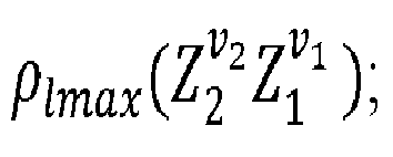
- the algorithm calculates: ⁇ lmax Z 2 v 2 Z 1 v 1 i.e. the spectral radius ⁇ lmax of the product of the first for the second transformation matrices, which are respectively raised to the corresponding number of revolutions v 1 , v 2 .
- the algorithm identifies the pair of working heights h w 1 * h w 2 * corresponding to the smallest spectral radius .
- the algorithm can be configured to plot a gain map, i.e. a graph showing the variation of the spectral radius ⁇ lmax of the product of the first for the second transformation matrices, as a function of the pairs of working heights ( h w 1 , h w 2 ).
- a gain map is shown in Figure 2 .
- the operator of the grinding machine will select the pair of working heights that minimize the spectral radius ⁇ lmax .
- the alternative of using a gain map is feasible if the working steps are at most three, since the gain map can be easily read and interpreted at most in the three dimensions.
- the spectral radius ⁇ lmax of a matrix is defined as the supremum among the absolute values of the elements in its spectrum, in simple words it is the eigenvalue of the matrix having the largest absolute value.
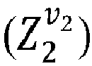
- each eigenvalue of the product of the transformation matrices Z 2 v 2 Z 1 v 1 is associated with a specific amplification factor of the waviness of the workpiece 100, for example, after proper sorting, the fifth eigenvalue is associated with the waviness having five lobes on the surface of the workpiece.
- identifying the pair of working heights ( h w 1 , h w 2 ) corresponding to the smallest spectral radius of the product of the transformation matrices Z 2 v 2 Z 1 v 1 means searching for the pair of working heights ( h w 1 , h w 2 ) that minimize the waviness that will prevail on the workpiece at the end of the machining process.
- the pair of machining heights that minimize ⁇ lmax Z 2 v 2 Z 1 v 1 are therefore the pair of optimal machining heights that minimize lobing, and thus maximize the roundness of the workpiece 100 at the end of the machining process.
- ⁇ l max that is, like the eigenvalue of Z 2 v 2 Z 1 v 1 having the maximum absolute value among the eigenvalues, of the same matrix Z 2 v 2 Z 1 v 1 , having an imaginary part ranging from 1 to a maximum value l max , preferably equal to 30.
- this method of calculating the spectral radius can exclude the eigenvalues associated with the profiles having a high number of lobes, i.e.can exclude the numerical solutions that cannot be physically obtained.
- the geometric parameters of the grinding machine that the algorithm receives as inputs comprise the above-discussed blade angle ⁇ .
- the geometric parameters of the grinding machine 1 that the algorithm receives as inputs also comprise the first grinding wheel diameter d s and the second grinding wheel diameter d wc .
- the geometric parameters of the workpiece to be provided as inputs to the algorithm comprise the diameter d p of the workpiece 100 before starting the first working step.
- the first and second transformation matrices Z 1 ,Z 2 describe the evolution of the diameter or the radius of the workpiece 100 respectively, after one revolution, during the first and second working steps.
- the method of the present invention can continuously vary the working height h w during the grinding process.
- the supporting blade is configured to continuously move the workpiece during machining, from the first working height h w 1 to the second working height h w 2 according to a specific mathematical law.
- the numerical control of the grinding machine must simultaneously adjust the position of the grinding wheels to maintain a correct contact condition.
- the transformation matrix Z of the general working step is obtained from the reduction radius r ( ⁇ ).
- the reduction radius r ( ⁇ ) indicates the reduction of the radius of the workpiece during the grinding process, and is a function of the angular position ⁇ of the workpiece.
- the cutting depth I ( ⁇ ) is obtained from the feeding movement of the second grinding wheel, which causes the first grinding wheel to be juxtaposed against the workpiece, as designated in Figure 1 by X ( ⁇ ).
- the current cutting depth I ( ⁇ ) may be deemed to be equal to a stiffness coefficient of the machine k multiplied by the geometric cutting depth I g ( ⁇ ), that is, the cutting depth that would be obtained if the grinding machine were perfectly rigid.
- a further object of the present invention is to provide a computer program that can be loaded into the memory of a computer, and configured to cause a grinding machine, namely a centerless plunge grinding machine, to perform the above-described method.
- an object of the present invention is a grinding machine 1 comprising a first grinding wheel and a second grinding wheel 2a, 2b separated by an gap and having a first rotation axis and a second rotation axis A-A, B-B respectively.
- the grinding wheels 2a, 2b preferably have a cylindrical or conical shape, are configured to both contact a workpiece 100, to rotate it and perform material removal.
- the grinding machine 1 also comprises a supporting blade 3, arranged in the gap and configured to support the workpiece 100. More in detail, the supporting blade 3 is configured to place the workpiece 100 at a given working height ( h w ) from a plane containing the first rotation axis A-A and the midpoint of the second rotation axis.
- the midpoint of the second rotation axis B-B refers to the median point of the height of the second grinding wheel h M 2 .
- the grinding machine 1 comprises a regulating device (not shown) for moving the supporting blade 3.
- the regulating device is configured to move the supporting blade 3 in a direction substantially perpendicular to the plane containing the first rotation axis A-A and the midpoint of the second rotation axis B-B to change the working height h w at which the workpiece 100 is located.
- the grinding machine 1 comprises a processor having a memory in which the aforementioned computer program is loaded.
- the computer program when loaded into the memory and implemented by the computer, is configured to perform the above method.
- the computer program may reside on a cloud, on a smartphone or on a tablet separate from the machine. This is possible because the computer program is designed to plan machining and does not require direct connection with the grinding machine.
- the process parameters provided by the computer program may be transferred directly to the numerical control of the machine or manually entered by the operator.
- the machine tool further comprises a numerical control, which is able to communicate with the computer on which the computer program is loaded.
- the numerical control is configured to operate the regulating device to place the workpiece 100 at different working heights during the different working steps.
Landscapes
- Engineering & Computer Science (AREA)
- Mechanical Engineering (AREA)
- Grinding Of Cylindrical And Plane Surfaces (AREA)
- Constituent Portions Of Griding Lathes, Driving, Sensing And Control (AREA)
- Finish Polishing, Edge Sharpening, And Grinding By Specific Grinding Devices (AREA)
Abstract


Description
- The present invention relates to a method of minimizing waviness on a workpiece by a grinding process, namely a centerless plunge grinding process, as defined in the preamble of claim 1.
- The present invention also relates to a computer program designed to be loaded into the memory of a computer and adapted to cause the grinding machine to perform the method of the present invention.
- Finally, the present invention also relates to a grinding machine which comprises a computer having a memory in which the computer program for causing performance of the method of the present invention is loaded.
- The centerless plunge grinding process and the machine tools for implementing it are well known in the art.
- In this grinding process, a workpiece is arranged between two grinding wheels and supported by a blade. This particular configuration, with a three-point support of the workpiece, exposes the process to roundness errors, since the workpiece is free to oscillate during machining, thereby generating a plurality of lobes on its surface. This roundness error is known as "lobing".
- Certain prior art centerless grinding machines can minimize lobe formation on the workpiece profile.
- For example,
US 20040209558 A1 discloses a centerless grinding method in which the supporting blade during machining is configured to change the position of the workpiece to prevent the occurrence of lobes on the workpiece profile. - Workpiece position adjustment is performed step by step during machining based on certain process parameters that are continuously acquired during machining. Such parameters may be, for example, the diameter of the workpiece or the roundness of its profile.
- One drawback of prior art methods of minimizing the width of the lobes on the workpiece profile is that they require the installation of specific measuring instruments, which complicate the architecture of the grinding machine and increases its cost.
- Therefore, the object of the present invention is to provide a method of minimizing waviness on a workpiece that can be easily implemented with commercially available grinding machines.
- The aforementioned technical purpose and objects are substantially achieved by a method of minimizing waviness on a workpiece as defined in claim 1.
- The method of the present invention first requires the provision of a grinding machine, comprising a first grinding wheel or driving grinding wheel, and a second grinding wheel or driven grinding wheel, respectively configured to rotate about a first rotation axis and a second rotation axis, and a supporting blade arranged between the first and second grinding wheels, for supporting the workpiece during the grinding process. In detail, the supporting blade has a contact surface that is inclined with respect to a plane containing the rotation axes of the grinding wheels by a blade angle. Furthermore, the grinding machine comprises a regulating device for moving the supporting blade in a direction perpendicular to the plane containing the first rotation axis and the midpoint of the second, to change the working height. Preferably, this grinding machine is a centerless plunge grinding machine.
- The method comprises at least one first working step and one second working step in which the workpiece completes first and second numbers of rotations, respectively. In detail, during the first and second working steps, the supporting blade is configured to place the workpiece at a first working height and a second working height respectively with respect to a plane containing the first rotation axis (A-A) and the midpoint of the second rotation axis (B-B). In other words, the supporting blade is configured to change the working height of the workpiece through the various steps of the grinding process.
- The method is characterized in that the first and second working heights are determined before the first working step, by means of an optimization algorithm for determining the optimum working heights to minimize both the existing waviness on the workpiece and the waviness caused by the grinding process.
- Therefore, the method of the present invention can advantageously minimize workpiece waviness without requiring changes to be made to prior art known grinding machines.
- Thus, advantageously, the method of the present invention does not require continuous monitoring of the process and hence the installation of specific measuring instruments on the grinding machine.
- Further features and advantages of the present invention will result more clearly from the illustrative, non-limiting description of a preferred, non-exclusive embodiment of a method, a computer program and grinding machine for minimizing waviness on a workpiece by a grinding process, as shown in the annexed drawings, in which:
-
Figure 1 shows a diagrammatic illustration of the grinding machine for performing the method of the present invention; -
Figure 2 shows an example of a gain map that can be obtained with the method of the present invention, which gain map can be used by an operator of the grinding machine to determine the optimum working heights of the first and second working steps. -
Figure 3 shows a side view of the grinding machine ofFigure 1 . - Even when not expressly stated, the individual features as described with reference to the particular embodiments shall be intended as auxiliary to and/or interchangeable with other features described with reference to other exemplary embodiments.
- Referring to the accompanying figures, the present invention relates to a method of minimizing waviness on a workpiece by a grinding process.
- As used herein, minimizing waviness refers both to minimizing the existing waviness on the workpiece and to minimizing the waviness caused by the grinding process itself.
- The method requires the provision of a grinding machine 1, preferably a centerless plunge grinding machine, comprising a pair of grinding
wheels Figure 1 , the grinding machine 1 comprises afirst grinding wheel 2a, whose size is defined by a first grinding wheel diameter ds , and a second grindingwheel 2b defined by a second grinding wheel diameter dwc . Typically, but without limitation, the first grinding wheel diameter ds is greater than the second grinding wheel diameter dwc . - Referring to
Figure 3 , the first grinding wheel and thesecond grinding wheel - In detail, the first and second grinding
wheels workpiece 100 to abutment against anabutment pad 4. - The first and
second grinding wheels grinding wheels first grinding wheel 2a along the first rotation axis A-A, the height of the second grinding wheel h M2 is defined as the extent of thesecond grinding wheel 2b along the second rotation axis B-B. - The first and second grinding
wheels workpiece 100. - The distance between the first and
second grinding wheels wheels - In operation, as each
grinding wheel - As shown in
Figure 1 , the grinding machine 1 further comprises a supportingblade 3 arranged in the gap, i.e. between the first andsecond grinding wheels workpiece 100. - In detail, the supporting
blade 3 has acontact surface 3a adapted to bearingly receive theworkpiece 100 to place it at a given working height hw from a plane containing the first rotation axis A-A and the midpoint of the second rotation axis B-B. - As used herein, the midpoint of the second rotation axis B-B refers to the median point of the height of the second grinding wheel h M2. Namely, the midpoint of the second rotation axis is the point that divides the height of the second grinding wheel h M2 into two equivalent segments, i.e. segments having the same length.
- As the supporting
blade 3 changes its position, specifically by moving in a direction orthogonal to the plane containing the first rotation axis A-A and the midpoint of the second rotation axis B-B, it changes the position of theworkpiece 100 in the gap, thereby modifying the working height hw. - More in detail, the supporting
blade 3 has acontact surface 3a which is adapted to abut against theworkpiece 100 to support it. Preferably, thecontact surface 3a is inclined by a blade angle γ with respect to the plane containing the first rotation axis A-A and the midpoint of the second rotation axis B-B. - The
blade 3 may be moved in the gap either manually by an operator, or, as in certain recent grinding machines, by numerical control. - The above-discussed grinding machine 1 is known in the art as "centerless plunge grinding machine".
- As mentioned above and known to the skilled person, this type of grinding machine 1 affords a very fast grinding process but is prone to roundness errors. The reason is that the center of the
workpiece 100 is free to oscillate during machining, thereby generating a lobed profile instead of a perfectly rounded profile. This roundness error is known in the art as "lobing". - Lobing is mainly influenced by the diameter of the first and second grinding wheels ds, dwc , the diameter of the workpiece, the blade angle γ and the working height hw.
- The method of the present invention is designed to minimize the formation of waviness on the workpiece, and to reduce existing waviness, by dividing the grinding process into several working steps, each characterized by a different working height hw.
- Referring to
Figure 1 , the working height hw refers to the distance of the center of theworkpiece 100 from the plane containing the first rotation axis A-A and the midpoint of the second rotation axis B-B. - The succession of different steps, characterized by different working heights hw, provides a negative growth rate for the lobes that tend to form on the workpiece, whereby a good roundness of the workpiece can be quickly achieved.
- While the method of the present invention may generally envisage an arbitrary number of working steps, however it has been experimentally found that two steps are sufficient to achieve a satisfactory roundness.
- Furthermore, the two-step solution is preferable in that it matches the common division of machining processes into "roughing" and "finishing" steps, which already applies to grinding, by changing the speed and feed parameters but not the working height hw.
- While the two-step machining method will be described below, it should be noted that the method of the present invention can be alternatively implemented with any finite number of steps greater than two, possibly a number of steps that can discretize a continuous height variation.
- The method of the present invention includes a first working step in which the supporting
blade 3 is configured to place theworkpiece 100 at a first working height h w1 with respect to a plane containing the first rotation axis A-A and the midpoint of the second rotation axis B-B. - During the first working step, the pair of grinding
wheels workpiece 100 until it completes a first number of revolutions v 1, in other words, the first working step shall be deemed to be finished when the workpiece has completed v 1 revolutions. - The method of the present invention also includes a second working step following the above-described first working step.
- In the second working step, the supporting
blade 3 is configured to place theworkpiece 100 at a second working height h w2 that differs from the first working height h w1. During the second working step, the pair of grindingwheels - According to a peculiar aspect of the present description, the first and second working heights h w1, h w2 are determined before the first working step by means of an algorithm which receives as inputs geometric parameters of the grinding machine 1, geometric parameters of the
workpiece 100 and an array of pairs of heights of the first and second working steps (h w1, h w2), and can thus determine the pair of heights of the first and second working step
- Preferably, the array of working heights (h w1, h w2) is a grid of equally spaced values in which h w1 varies between h w1 min and h w1 max , whereas h w2 varies between h w2 min and h w2 max .
- In detail, the algorithm calculates, for each pair of working heights (h w1, h w2), a first and a second transformation matrices Z 1, Z 2.
- The first and second transformation matrices Z 1, Z 2 describe the evolution of the geometry of the
workpiece 100 for a single revolution during the first and second working steps. More details will be given hereinbelow about the procedure for calculating the transformation matrices Z 1, Z 2. - Then, the algorithm calculates:

- Then, the algorithm identifies the pair of working heights

- Alternatively, the algorithm can be configured to plot a gain map, i.e. a graph showing the variation of the spectral radius ρlmax of the product of the first for the second transformation matrices, as a function of the pairs of working heights (h w1, h w2). An example of a gain map is shown in
Figure 2 . - In this case, the operator of the grinding machine will select the pair of working heights that minimize the spectral radius ρlmax. The alternative of using a gain map is feasible if the working steps are at most three, since the gain map can be easily read and interpreted at most in the three dimensions.
- In general, the spectral radius ρlmax of a matrix is defined as the supremum among the absolute values of the elements in its spectrum, in simple words it is the eigenvalue of the matrix having the largest absolute value.
- Here, each eigenvalue of the product of the transformation matrices

workpiece 100, for example, after proper sorting, the fifth eigenvalue is associated with the waviness having five lobes on the surface of the workpiece. The greater the absolute value of an eigenvalue, the more the specific waviness associated with that eigenvalue will be amplified on the workpiece profile at the end of the machining process. - Thus, identifying the pair of working heights (h w1, h w2) corresponding to the smallest spectral radius of the product of the transformation matrices

- The pair of machining heights that minimize

workpiece 100 at the end of the machining process. - Preferably, the spectral radius is calculated as follows:


- Advantageously, this method of calculating the spectral radius can exclude the eigenvalues associated with the profiles having a high number of lobes, i.e.can exclude the numerical solutions that cannot be physically obtained.
- Preferably, the geometric parameters of the grinding machine that the algorithm receives as inputs comprise the above-discussed blade angle γ.
- Also preferably, the geometric parameters of the grinding machine 1 that the algorithm receives as inputs also comprise the first grinding wheel diameter ds and the second grinding wheel diameter dwc.
- Preferably, the geometric parameters of the workpiece to be provided as inputs to the algorithm comprise the diameter dp of the
workpiece 100 before starting the first working step. - Preferably, the first and second transformation matrices Z1,Z2 describe the evolution of the diameter or the radius of the
workpiece 100 respectively, after one revolution, during the first and second working steps. - Alternatively, the method of the present invention can continuously vary the working height hw during the grinding process. In detail, the supporting blade is configured to continuously move the workpiece during machining, from the first working height h w1 to the second working height h w2 according to a specific mathematical law. The numerical control of the grinding machine must simultaneously adjust the position of the grinding wheels to maintain a correct contact condition.
- The mathematical procedure for calculating the transformation matrix Z of a general working step will be now described. Such procedure applies, notwithstanding certain differences, to the calculation of both the first transformation matrix Z 1, and the second transformation matrix Z2 or, more generally, the transformation matrix of the i-th working step Zi .
- The transformation matrix Z of the general working step is obtained from the reduction radius r(θ). The reduction radius r(θ), as the name implies, indicates the reduction of the radius of the workpiece during the grinding process, and is a function of the angular position θ of the workpiece. The reduction radius r(θ) increases its value during the grinding process and is equal to the sum of the reduction radius at the previous revolution r(θ - 2π) and the current cutting depth I(θ). Namely:

- The cutting depth I(θ) is obtained from the feeding movement of the second grinding wheel, which causes the first grinding wheel to be juxtaposed against the workpiece, as designated in
Figure 1 by X(θ). - Considering the stiffness of the grinding machine 1, the current cutting depth I(θ) may be deemed to be equal to a stiffness coefficient of the machine k multiplied by the geometric cutting depth Ig (θ), that is, the cutting depth that would be obtained if the grinding machine were perfectly rigid.
- In mathematical terms, the geometric cutting depth Ig (θ) is obtained by calculating the intersection between the first grinding wheel and the workpiece, considering the feeding movement of the second grinding wheel X(θ) and the displacement of the center of the workpiece. Namely:

- The angles θ,α and β are indicated in
Figure 1 , whereas the geometric coefficients K 1 and K 2 are a function of the working height hw. By replacing I(θ) in r(θ):
- The above equation represents the evolution of the workpiece profile during the machining process and is a Pure Delay Equation that can be solved by discretizing the workpiece into circumferential components:


- The above equation r(θ) can be thus rewritten as:


- It should be noted from the above equation that the evolution of the workpiece profile implies preservation of all discrete States from rj to r j-M-1 . The above equation rewritten in matrix form is:

- A further object of the present invention is to provide a computer program that can be loaded into the memory of a computer, and configured to cause a grinding machine, namely a centerless plunge grinding machine, to perform the above-described method.
- Finally, an object of the present invention is a grinding machine 1 comprising a first grinding wheel and a
second grinding wheel wheels workpiece 100, to rotate it and perform material removal. - The grinding machine 1 also comprises a supporting
blade 3, arranged in the gap and configured to support theworkpiece 100. More in detail, the supportingblade 3 is configured to place theworkpiece 100 at a given working height (hw ) from a plane containing the first rotation axis A-A and the midpoint of the second rotation axis. - Once again it should be noted that, as used herein, the midpoint of the second rotation axis B-B refers to the median point of the height of the second grinding wheel h M2.
- In addition, the grinding machine 1 comprises a regulating device (not shown) for moving the supporting
blade 3. In detail, the regulating device is configured to move the supportingblade 3 in a direction substantially perpendicular to the plane containing the first rotation axis A-A and the midpoint of the second rotation axis B-B to change the working height hw at which theworkpiece 100 is located. - The grinding machine 1 comprises a processor having a memory in which the aforementioned computer program is loaded. In detail, the computer program, when loaded into the memory and implemented by the computer, is configured to perform the above method.
- No run-time connection is required between the computer program and the grinding machine, as the machining data can be sent to the grinding machine before starting the machining process.
- In alternative embodiments of the grinding machine, the computer program may reside on a cloud, on a smartphone or on a tablet separate from the machine. This is possible because the computer program is designed to plan machining and does not require direct connection with the grinding machine. The process parameters provided by the computer program may be transferred directly to the numerical control of the machine or manually entered by the operator.
- The machine tool further comprises a numerical control, which is able to communicate with the computer on which the computer program is loaded.
- In detail, the numerical control is configured to operate the regulating device to place the
workpiece 100 at different working heights during the different working steps. Those skilled in the art will obviously appreciate that a number of changes and variants as described above may be made to fulfill particular requirements, without departure from the scope of the invention, as defined in the following claims.
Claims (8)
- A method of minimizing waviness on a workpiece (100) having a diameter (dp ) by a grinding process, the method comprising the steps of:- providing a grinding machine (1) comprising a first grinding wheel and a second grinding wheel (2a, 2b), and a supporting blade (3) arranged between the grinding wheels (2a, 2b), the first and second grinding wheels (2a, 2b) being respectively configured to rotate about a first rotation axis and a second rotation axis (A-A, B-B), the supporting blade (3) having a contact surface (3a) configured to support the workpiece (100), said contact surface (3a) being inclined with respect to a plane containing the axes of rotation of the grinding wheels (2a, 2b) by a blade angle (γ), the grinding machine (1) further comprising a regulating device adapted to move the supporting blade (3) in a direction perpendicular to the plane containing the first rotation axis (A-A) and the midpoint of the second rotation axis (B-B) to change the working height (hw ) of the workpiece (100);- performing, by said grinding machine (1), a first working step in which the workpiece completes a first number of revolutions (v 1), and in which the supporting blade (3) places the workpiece (100) at a first working height (h w1) from a plane containing the first rotation axis (A-A) and the midpoint of the second rotation axis (B-B);- performing, by said grinding machine (1), a second working step, next to the first working step, in which the workpiece (100) completes a second number of revolutions (v 2), and the supporting blade (3) places the workpiece (100) at a second working height (h w2) from the plane containing the first rotation axis (A-A) and the midpoint of the second rotation axis (B-B), the second working height (h w2) being different from the first working height (h w1);
said method being characterized in that the first and second working heights (h w1, h w2) are determined before the first working step, by means of an algorithm which receives, as inputs, geometric parameters of the grinding machine (1), comprising at least the blade angle (γ), geometric parameters of the workpiece (100), comprising the diameter (dp ) of the workpiece (100), the first and second number of revolutions (v 1, v 2), and an array of pairs of first and second working heights (h w1, h w2), said algorithm being configured to:- calculate, for each pair of working heights (h w1, h w2) a first transformation matrix
 - calculate, for each pair of working heights (h w1, h w2) the spectral radius (ρlmax ) of the product of the first and the second transformation matrices
 - outputting the pair of working heights
- A method as claimed in any of the preceding claims, wherein the size of each grinding wheel (2a, 2b) is defined by a grinding wheel diameter, the geometric parameters of the grinding machine (1) to be provided as inputs to the algorithm comprising the diameter of each grinding wheel.
- A method as claimed in any of the preceding claims, wherein the transformation matrix of the first and second working steps

- A method as claimed in any of the preceding claims, wherein the supporting blade (3) is configured to continuously move the workpiece (100) from the first working height to the second working height (h w1, h w2)) according to a specific mathematical law without interrupting the machining of the workpiece.
- A method as claimed in any of the preceding claims, wherein the spectral radius of a matrix Z is calculated as the eigenvalue of the matrix Z having the maximum absolute value among eigenvalues, of the same matrix Z, having an imaginary part ranging from 1 to a maximum value (lmax ), in symbols:

- A computer program for minimizing waviness on a workpiece (100) by a grinding process, said program being adapted to be loaded into a memory of a processor of a grinding machine (1),
said computer program being configured to perform the method for minimizing waviness on a workpiece as claimed in any of the preceding claims. - A grinding machine (1) comprising:- a first grinding wheel and a second grinding wheel (2a, 2b) separated by a gap and configured to rotate about a first rotation axis and a second rotation axis (A-A, B-B) respectively, the grinding wheels (2a, 2b) being configured to both contact a workpiece (100) to work thereupon as it rotates;- a supporting blade (3) located in the gap and configured to support the workpiece (100) while placing it at a predetermined working height (hw ) from a plane containing the first rotation axis (A-A) and the midpoint of the second rotation axis (B-B);- a regulating device for moving the supporting blade (3) in a direction perpendicular to the plane containing the first rotation axis (A-A) and the midpoint of the second rotation axis (B-B) to change the working height (hw ) of the workpiece (100); characterized in that it comprises a processor having a memory in which said computer program as claimed in claim 6 is loaded, said computer program, when implemented by said processor, being configured to perform the method as claimed in any of claims 1 to 5.
- A grinding machine (1) as claimed in claim 7, comprising a numerical control that is able to communicate with the computer in which the computer program is loaded, and configured to operate the regulating device to place the workpiece (100) at different working heights (hw ) during the different working steps.
Applications Claiming Priority (1)
| Application Number | Priority Date | Filing Date | Title |
|---|---|---|---|
| IT102020000022861A IT202000022861A1 (en) | 2020-09-28 | 2020-09-28 | METHOD FOR MINIMIZING WIPES ON A WORKPIECE BY A GRINDING PROCESS |
Publications (2)
| Publication Number | Publication Date |
|---|---|
| EP3974106A1 true EP3974106A1 (en) | 2022-03-30 |
| EP3974106B1 EP3974106B1 (en) | 2025-09-24 |
Family
ID=73699338
Family Applications (1)
| Application Number | Title | Priority Date | Filing Date |
|---|---|---|---|
| EP21198968.6A Active EP3974106B1 (en) | 2020-09-28 | 2021-09-24 | Method of minimizing waviness on a workpiece by a grinding process, computer program and grinding machine for making the same |
Country Status (2)
| Country | Link |
|---|---|
| EP (1) | EP3974106B1 (en) |
| IT (1) | IT202000022861A1 (en) |
Cited By (1)
| Publication number | Priority date | Publication date | Assignee | Title |
|---|---|---|---|---|
| US12611746B1 (en) * | 2024-12-27 | 2026-04-28 | Tianjin University | Over-positioning grinding method of hard and brittle pipe fitting with large length-to-diameter ratio |
Citations (4)
| Publication number | Priority date | Publication date | Assignee | Title |
|---|---|---|---|---|
| US5643051A (en) * | 1995-06-16 | 1997-07-01 | The University Of Connecticut | Centerless grinding process and apparatus therefor |
| US5691909A (en) * | 1995-12-29 | 1997-11-25 | Western Atlas | Method of virtual machining to predict the accuracy of part to be made with machine tools |
| US20040209558A1 (en) | 2001-08-14 | 2004-10-21 | Erwin Junker | Method and device for centerless cylindrical grinding |
| US20110306273A1 (en) * | 2010-06-14 | 2011-12-15 | Urs Tschudin | Centerless cylindrical grinding machine and centerless grinding method with height-adjustable regulating wheel |
-
2020
- 2020-09-28 IT IT102020000022861A patent/IT202000022861A1/en unknown
-
2021
- 2021-09-24 EP EP21198968.6A patent/EP3974106B1/en active Active
Patent Citations (4)
| Publication number | Priority date | Publication date | Assignee | Title |
|---|---|---|---|---|
| US5643051A (en) * | 1995-06-16 | 1997-07-01 | The University Of Connecticut | Centerless grinding process and apparatus therefor |
| US5691909A (en) * | 1995-12-29 | 1997-11-25 | Western Atlas | Method of virtual machining to predict the accuracy of part to be made with machine tools |
| US20040209558A1 (en) | 2001-08-14 | 2004-10-21 | Erwin Junker | Method and device for centerless cylindrical grinding |
| US20110306273A1 (en) * | 2010-06-14 | 2011-12-15 | Urs Tschudin | Centerless cylindrical grinding machine and centerless grinding method with height-adjustable regulating wheel |
Cited By (1)
| Publication number | Priority date | Publication date | Assignee | Title |
|---|---|---|---|---|
| US12611746B1 (en) * | 2024-12-27 | 2026-04-28 | Tianjin University | Over-positioning grinding method of hard and brittle pipe fitting with large length-to-diameter ratio |
Also Published As
| Publication number | Publication date |
|---|---|
| EP3974106B1 (en) | 2025-09-24 |
| IT202000022861A1 (en) | 2022-03-28 |
Similar Documents
| Publication | Publication Date | Title |
|---|---|---|
| EP1475202B1 (en) | Slitter apparatus with compensating device for slitter blades | |
| US5715807A (en) | Wire saw | |
| US9760079B2 (en) | Cutting tool machining method and a wire electric discharge machine | |
| JP4425592B2 (en) | Deep groove milling method and milling tool | |
| EP3974106B1 (en) | Method of minimizing waviness on a workpiece by a grinding process, computer program and grinding machine for making the same | |
| US4942611A (en) | Method of correcting misalignment of a workpiece on numerically controlled machine tool | |
| JP2940027B2 (en) | Grinding method with grinding force control | |
| EP0324959B1 (en) | Method for correcting tyre deflection in tyre grooving and apparatus therefor | |
| US4571891A (en) | Apparatus for compensating for dressing tool wear during the dressing of grinding wheels | |
| US20190270141A1 (en) | Method for manufacturing machine component, apparatus for manufacturing machine component, method for machining rotation symmetry plane, recording medium, and program | |
| US9849547B2 (en) | Manufacturing apparatus and manufacturing method for manufacturing less unbalanced blower blade | |
| US4620463A (en) | Process for machining tubular parts and apparatus for carrying out the process | |
| US6277004B1 (en) | Phase adjusting method and recess machining apparatus and method | |
| EP0974883B1 (en) | Methods and apparatus for grinding concentric cylindrical workpiece regions | |
| US20020182979A1 (en) | Computer controlled grinding machine | |
| KR0157664B1 (en) | How to fix and angle the cutter blade by grinding | |
| JP2843488B2 (en) | Machine tool control method and control device | |
| CN101154098A (en) | Program writing method of numerical controller, numerical controller and cutting machine controlled thereby | |
| KR102864295B1 (en) | Apparatus and method for correcting unbalance of rotating workpiece | |
| GB2196274A (en) | Process and machine for producing piston rings | |
| JPH11188621A (en) | Method and apparatus for correcting taper in grinding machine | |
| JP2002127010A (en) | Regulating wheel truing method and device for centerless grinder | |
| JP2710621B2 (en) | Unbalance correction device | |
| JP2512753B2 (en) | Grinding machine feed control device | |
| JP2004050380A (en) | Centerless grinding method and centerless grinding machine |
Legal Events
| Date | Code | Title | Description |
|---|---|---|---|
| PUAI | Public reference made under article 153(3) epc to a published international application that has entered the european phase |
Free format text: ORIGINAL CODE: 0009012 |
|
| STAA | Information on the status of an ep patent application or granted ep patent |
Free format text: STATUS: THE APPLICATION HAS BEEN PUBLISHED |
|
| AK | Designated contracting states |
Kind code of ref document: A1 Designated state(s): AL AT BE BG CH CY CZ DE DK EE ES FI FR GB GR HR HU IE IS IT LI LT LU LV MC MK MT NL NO PL PT RO RS SE SI SK SM TR |
|
| STAA | Information on the status of an ep patent application or granted ep patent |
Free format text: STATUS: REQUEST FOR EXAMINATION WAS MADE |
|
| 17P | Request for examination filed |
Effective date: 20220930 |
|
| RBV | Designated contracting states (corrected) |
Designated state(s): AL AT BE BG CH CY CZ DE DK EE ES FI FR GB GR HR HU IE IS IT LI LT LU LV MC MK MT NL NO PL PT RO RS SE SI SK SM TR |
|
| RAP3 | Party data changed (applicant data changed or rights of an application transferred) |
Owner name: MONZESI S.P.A. SOCIETA BENEFIT Owner name: CONSIGLIO NAZIONALE DELLE RICERCHE |
|
| GRAP | Despatch of communication of intention to grant a patent |
Free format text: ORIGINAL CODE: EPIDOSNIGR1 |
|
| STAA | Information on the status of an ep patent application or granted ep patent |
Free format text: STATUS: GRANT OF PATENT IS INTENDED |
|
| INTG | Intention to grant announced |
Effective date: 20250506 |
|
| GRAS | Grant fee paid |
Free format text: ORIGINAL CODE: EPIDOSNIGR3 |
|
| GRAA | (expected) grant |
Free format text: ORIGINAL CODE: 0009210 |
|
| STAA | Information on the status of an ep patent application or granted ep patent |
Free format text: STATUS: THE PATENT HAS BEEN GRANTED |
|
| AK | Designated contracting states |
Kind code of ref document: B1 Designated state(s): AL AT BE BG CH CY CZ DE DK EE ES FI FR GB GR HR HU IE IS IT LI LT LU LV MC MK MT NL NO PL PT RO RS SE SI SK SM TR |
|
| REG | Reference to a national code |
Ref country code: GB Ref legal event code: FG4D |
|
| REG | Reference to a national code |
Ref country code: CH Ref legal event code: EP |
|
| REG | Reference to a national code |
Ref country code: DE Ref legal event code: R096 Ref document number: 602021039052 Country of ref document: DE |
|
| PGFP | Annual fee paid to national office [announced via postgrant information from national office to epo] |
Ref country code: AT Payment date: 20251020 Year of fee payment: 5 |
|
| REG | Reference to a national code |
Ref country code: IE Ref legal event code: FG4D |
|
| PG25 | Lapsed in a contracting state [announced via postgrant information from national office to epo] |
Ref country code: NO Free format text: LAPSE BECAUSE OF FAILURE TO SUBMIT A TRANSLATION OF THE DESCRIPTION OR TO PAY THE FEE WITHIN THE PRESCRIBED TIME-LIMIT Effective date: 20251224 |
|
| REG | Reference to a national code |
Ref country code: LT Ref legal event code: MG9D |
|
| PG25 | Lapsed in a contracting state [announced via postgrant information from national office to epo] |
Ref country code: FI Free format text: LAPSE BECAUSE OF FAILURE TO SUBMIT A TRANSLATION OF THE DESCRIPTION OR TO PAY THE FEE WITHIN THE PRESCRIBED TIME-LIMIT Effective date: 20250924 |
|
| PG25 | Lapsed in a contracting state [announced via postgrant information from national office to epo] |
Ref country code: HR Free format text: LAPSE BECAUSE OF FAILURE TO SUBMIT A TRANSLATION OF THE DESCRIPTION OR TO PAY THE FEE WITHIN THE PRESCRIBED TIME-LIMIT Effective date: 20250924 |
|
| PG25 | Lapsed in a contracting state [announced via postgrant information from national office to epo] |
Ref country code: GR Free format text: LAPSE BECAUSE OF FAILURE TO SUBMIT A TRANSLATION OF THE DESCRIPTION OR TO PAY THE FEE WITHIN THE PRESCRIBED TIME-LIMIT Effective date: 20251225 |
|
| PG25 | Lapsed in a contracting state [announced via postgrant information from national office to epo] |
Ref country code: SE Free format text: LAPSE BECAUSE OF FAILURE TO SUBMIT A TRANSLATION OF THE DESCRIPTION OR TO PAY THE FEE WITHIN THE PRESCRIBED TIME-LIMIT Effective date: 20250924 |
|
| PG25 | Lapsed in a contracting state [announced via postgrant information from national office to epo] |
Ref country code: LV Free format text: LAPSE BECAUSE OF FAILURE TO SUBMIT A TRANSLATION OF THE DESCRIPTION OR TO PAY THE FEE WITHIN THE PRESCRIBED TIME-LIMIT Effective date: 20250924 |
|
| PG25 | Lapsed in a contracting state [announced via postgrant information from national office to epo] |
Ref country code: BG Free format text: LAPSE BECAUSE OF FAILURE TO SUBMIT A TRANSLATION OF THE DESCRIPTION OR TO PAY THE FEE WITHIN THE PRESCRIBED TIME-LIMIT Effective date: 20250924 |
|
| PG25 | Lapsed in a contracting state [announced via postgrant information from national office to epo] |
Ref country code: RS Free format text: LAPSE BECAUSE OF FAILURE TO SUBMIT A TRANSLATION OF THE DESCRIPTION OR TO PAY THE FEE WITHIN THE PRESCRIBED TIME-LIMIT Effective date: 20251224 |
|
| REG | Reference to a national code |
Ref country code: NL Ref legal event code: MP Effective date: 20250924 |
|
| PG25 | Lapsed in a contracting state [announced via postgrant information from national office to epo] |
Ref country code: NL Free format text: LAPSE BECAUSE OF FAILURE TO SUBMIT A TRANSLATION OF THE DESCRIPTION OR TO PAY THE FEE WITHIN THE PRESCRIBED TIME-LIMIT Effective date: 20250924 |
|
| REG | Reference to a national code |
Ref country code: AT Ref legal event code: MK05 Ref document number: 1840040 Country of ref document: AT Kind code of ref document: T Effective date: 20250924 |
|
| PG25 | Lapsed in a contracting state [announced via postgrant information from national office to epo] |
Ref country code: SM Free format text: LAPSE BECAUSE OF FAILURE TO SUBMIT A TRANSLATION OF THE DESCRIPTION OR TO PAY THE FEE WITHIN THE PRESCRIBED TIME-LIMIT Effective date: 20250924 |
|
| PG25 | Lapsed in a contracting state [announced via postgrant information from national office to epo] |
Ref country code: ES Free format text: LAPSE BECAUSE OF FAILURE TO SUBMIT A TRANSLATION OF THE DESCRIPTION OR TO PAY THE FEE WITHIN THE PRESCRIBED TIME-LIMIT Effective date: 20250924 |
|
| PG25 | Lapsed in a contracting state [announced via postgrant information from national office to epo] |
Ref country code: AT Free format text: LAPSE BECAUSE OF FAILURE TO SUBMIT A TRANSLATION OF THE DESCRIPTION OR TO PAY THE FEE WITHIN THE PRESCRIBED TIME-LIMIT Effective date: 20250924 |
|
| PG25 | Lapsed in a contracting state [announced via postgrant information from national office to epo] |
Ref country code: IT Free format text: LAPSE BECAUSE OF FAILURE TO SUBMIT A TRANSLATION OF THE DESCRIPTION OR TO PAY THE FEE WITHIN THE PRESCRIBED TIME-LIMIT Effective date: 20250924 Ref country code: RO Free format text: LAPSE BECAUSE OF FAILURE TO SUBMIT A TRANSLATION OF THE DESCRIPTION OR TO PAY THE FEE WITHIN THE PRESCRIBED TIME-LIMIT Effective date: 20250924 |
|
| PG25 | Lapsed in a contracting state [announced via postgrant information from national office to epo] |
Ref country code: IS Free format text: LAPSE BECAUSE OF FAILURE TO SUBMIT A TRANSLATION OF THE DESCRIPTION OR TO PAY THE FEE WITHIN THE PRESCRIBED TIME-LIMIT Effective date: 20260124 |
|
| PG25 | Lapsed in a contracting state [announced via postgrant information from national office to epo] |
Ref country code: PT Free format text: LAPSE BECAUSE OF FAILURE TO SUBMIT A TRANSLATION OF THE DESCRIPTION OR TO PAY THE FEE WITHIN THE PRESCRIBED TIME-LIMIT Effective date: 20260126 Ref country code: CZ Free format text: LAPSE BECAUSE OF FAILURE TO SUBMIT A TRANSLATION OF THE DESCRIPTION OR TO PAY THE FEE WITHIN THE PRESCRIBED TIME-LIMIT Effective date: 20250924 |
|
| PG25 | Lapsed in a contracting state [announced via postgrant information from national office to epo] |
Ref country code: PL Free format text: LAPSE BECAUSE OF FAILURE TO SUBMIT A TRANSLATION OF THE DESCRIPTION OR TO PAY THE FEE WITHIN THE PRESCRIBED TIME-LIMIT Effective date: 20250924 |
|
| PG25 | Lapsed in a contracting state [announced via postgrant information from national office to epo] |
Ref country code: SK Free format text: LAPSE BECAUSE OF FAILURE TO SUBMIT A TRANSLATION OF THE DESCRIPTION OR TO PAY THE FEE WITHIN THE PRESCRIBED TIME-LIMIT Effective date: 20250924 Ref country code: EE Free format text: LAPSE BECAUSE OF FAILURE TO SUBMIT A TRANSLATION OF THE DESCRIPTION OR TO PAY THE FEE WITHIN THE PRESCRIBED TIME-LIMIT Effective date: 20250924 |
|
| REG | Reference to a national code |
Ref country code: CH Ref legal event code: H13 Free format text: ST27 STATUS EVENT CODE: U-0-0-H10-H13 (AS PROVIDED BY THE NATIONAL OFFICE) Effective date: 20260504 |